Abstract
There has been some research on jet electrolytic processing at home and abroad, and the phenomenon of discharge during the process has been reported, but there has been little research on the mode of jet electrolysis with the aid of discharge. A jet mask electrolytic processing experiment was set up to prepare a blue oil mask on the surface of the workpiece using photolithography; two processing modes were achieved using different tool electrodes, the workpiece was processed by two types of motion, the processing micro-pits were observed morphologically using an optical microscope, and the test data were analyzed by plotting graphs. Experiments show that a blue oil mask with a thickness of 50 μm covers the workpiece to strengthen the fixity, and that jet electrolytic discharge machining can effectively improve the depth-to-width ratio by increasing the contribution to depth by 30%–38% and the contribution to width by 2%–18%, compared to jet electrolytic machining. The former has less island effect than the latter, with a flatter bottom and better-machined shape.
1. Introduction
Jet electrolytic machining (Jet-ECM) is a special form of electrochemical machining (ECM) that uses an electrolytic jet as a tool. It offers advantages over other electrochemical machining processes such as good domain fixation, high machining speeds, and machining position flexibility [1,2]. The use of a displacement stage to drive the nozzle cathode to follow a pre-defined path enables rapid and precise fabrication of complex structures on the workpiece surface [3,4,5]. Hinduja and Pattavanitch [6] electrochemically machined a simple square pocket and a pocket with a humanoid protrusion, using tools with round and square electrodes. Hackert-Oschätzchen et al. [7] used a continuous electrolytic free jet to obtain a high degree of positioning in the removal area and electrochemically processed cavities with a depth of about 180 μm and a width of about 190 μm. Kawanaka and Kunieda [8] investigated the effect of current conditions and nozzle movement speed on the surface roughness of stainless steel, and achieved a mirror-like surface with Rz surface values of less than 0.2 μm. It was shown that the surface roughness of the cavities decreased as the nozzle translation speed increased, and that for constant speeds the surface roughness of the cavities decreased and increased again after reaching a minimum value [8,9,10].
Electrochemical discharge machining (ECDM) is considered to be a hybrid machining method. Material removal is based on two phenomena: electrochemical dissolution of the material and corrosion due to hot inter-electrode discharge [11,12]. Kim et al. [13] proposed an ECDM drilling method for glass workpieces, where a working fluid containing potassium hydroxide facilitated the process. Kobayashi [14] described a solution for obtaining shaped cavities by ECDM and electro-corrosion, using an electrolyte based on sodium nitrate. Liu, J.W. et al. [15] proposed a discharge mechanism analysis of electrochemical discharge machining of particle-reinforced metal matrix composites in electrolytic machining by dividing the time experienced by the discharge phenomenon of the output of the ECM process into three phases: electrolytic machining under the condition of power supply, electrolytic composite machining by arc discharge, and electrolytic machining under the condition of capacitive power supply. Yu, W. [16] mentioned in an experimental study of electrohydraulic beam machining of microstructures that spark discharge was generated between the nozzle and the workpiece at an initial machining gap of 0.5 mm, a feed rate of 0.1 mm/min, an electrolyte pressure of 0.3 MPa, an electrolyte solution of 18% NaNO3 and a machining voltage of 280 V. For Cui, J. [17], the study of the motion characteristics, electromagnetic characteristics, and oscillation of charged particles in the discharge channel is an important part of the research on the mechanism of EDM. Liu, H. and Xieeryazidan, A. [18] investigated the effect of energy distribution on electrochemical discharge machining, and experiments showed that the optimal combination of process parameters at 50 V voltage, 20 kHz frequency, and 80% duty cycle achieved a more uniform distribution of discharge energy, which was able to efficiently machine pairs of hard and fragile materials. Chuang et al. [19] utilized the interaction of electrochemical and EDM compensating techniques for the machining of CrNiFe alloy material machining; the machining accuracy was characterized by electrical pulse signal matching, processing time was reduced by 80%, and the efficiency of the equipment was improved. Sambathkumar and Arunagirinathan [20] investigated the working gap (Wg) between the tool and the workpiece in ECDM affecting the process parameters, and the results showed that even a difference of 2 μm in the Wg significantly affects the ECDM process in terms of quality and quantitative metrics. Zhao et al. [21] optimized the process without the loss of cathode tools by constructing a coupled multiphysics field model for electrochemical mask processing and combining it with numerical simulation analysis to realize the distribution state of multiphysics fields. Zhan and Zhao [22] proposed a plasma-assisted electrochemical machining method, where a higher voltage is applied to promote cathodic hydrogen precipitation, inducing a plasma discharge that leads to rapid heating of the electrolyte around the working electrode, which facilitates subsequent anodic etching by enhancing the kinetics of the electrochemical reaction. The material removal rate was increased by about 20 times, compared to ECM. Jui et al. [23] used electrochemical discharge machining to process microvias on glass with a high aspect ratio, of 11. Wang et al. [24]. proposed a novel electrochemical spark grinding composite machining method, which has lower discharge energy compared to conventional electrochemical discharge machining and solves the edge collapse and breakage problems.
Jet electrolytic discharge machining (Jet-ECDM) is a Jet-ECM with superimposed discharge effects and a special form of ECDM using a jet as a tool and using a mask for positional constraints; the model is unique and novel, most of the research is still in the early exploratory stage, and there are few production applications in practice.
The experimental setup of jet electrolytic machining with a mask covering the workpiece is established, and two models of Jet-MECM and Jet-MECDM are experimentally compared, using jet mask electrolytic machining and jet mask electrolytic discharge machining. The two modes of motion are used to machine the workpiece and analyze the morphological excavation characteristics of the machined workpiece, which is of great significance to the in-depth study of Jet-ECDM. This paper is dedicated to the above, providing a new method and theoretical basis for Jet-ECM.
2. Materials and Experimental Methodology
The experimental setup for jet mask electrolytic processing is shown in Figure 1. The machine mainly consists of a linear module for the machine, a working feeder for the servo motor, and a work table. The machine is mounted on a rigid marble base which has a large vibration resistance, poor thermal conductivity, and a coefficient of thermal expansion. To prevent small vibrations in the surroundings from being transmitted to the machine, an adjustable damping pad is installed under the base. The electromechanical control section consists mainly of Mitsubishi servo motors, a Renishaw micrograting system, and a motion control card from Shenzhen Raytheon. The human–machine interface is programmed using LabVIEW 2022, the NI virtual instrument development platform.
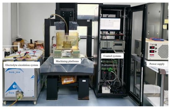
Figure 1.
Diagram of the experimental setup for electrolytic processing of jet masks.
The electrolyte circulation system consists of circulation tubes, pressure control valves, pressure gauges, and reservoirs, and is an important part of the laboratory processing equipment. The high-voltage pulse power supply has excellent characteristics, such as reliable precision and outstanding stability. Under the control of human–machine interaction, the motion platform can move along the x, y, and z axes to complete the precise machining of the workpiece. At the same time, fluctuations in current and voltage during online processing can be monitored in real time with a digital oscilloscope.
The main parameters of the machine tool equipment for jet mask electrolytic processing are shown in Table 1.

Table 1.
Main parameters of the machine tool equipment for jet mask electrolytic processing.
The self-developed jet mask electrolytic processing machine tool equipment, after parameter testing, reached the expected target, and the equipment control was a precise and stable operation, which laid a good foundation for experimental research.
Jet mask electrolytic machining technology is for making skeleton patterns on the mask and covering the mask on the surface of the anode workpiece; it uses NaNO3 electrolyte to spray processing on the workpiece, to make the workpiece surface obtain the same geometry as the mask skeleton pattern process method. This method solves the problem of complex, microfine tool electrodes and nozzles that are difficult to manufacture and assemble, and thus is widely used in the manufacture of surface micronano-structures, whose processing schematic diagram is shown in Figure 2.
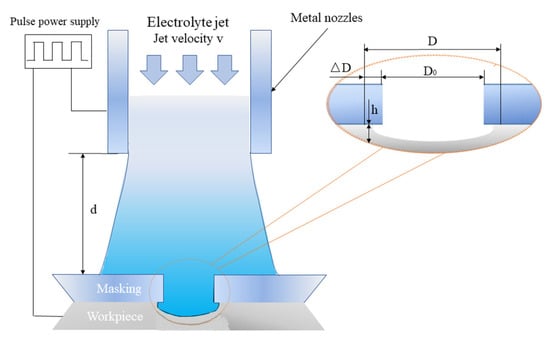
Figure 2.
Principle diagram of mask jet electrolytic processing.
As shown in Figure 2, the workpiece is connected to the positive pole of the power supply, and the metal nozzle is connected to the negative pole of the power supply; the electrolyte is driven by the pump, and rushes at high speed to the surface of the mask with the skeleton pattern. The high-speed charged electrolyte forms an array of liquid electrodes under the constraint of the high-resolution mask, and carries out mass etching of the anode workpiece material (the part covered by the mask is not processed, while the part not covered by the mask is processed), thus processing a structure similar to the mask skeleton pattern. At the same time, the use of the CNC motion stage enables the cathode nozzle to achieve scanning motion, increasing the flexibility of the process. The use of mask plates solves the problem of complex microfine tool electrodes that are difficult to manufacture and assemble, while the jet electrolytic processing and scanning motion not only avoids the need to design cavity fixtures to meet specific flow field requirements, but also increases processing flexibility by enabling the processing of many different types of the workpiece without changing the process method or fixture. The mature lithography process provides micro- and nanoscale insulating masks in a variety of patterns, enabling the process method to meet the processing requirements of a variety of applications. A comparison experiment was carried out between jet mask electrolytic discharge machining (Jet-MECDM) and jet-mask electrolytic machining (Jet-MECM), using a metal nozzle for the Jet-MECDM tool and a plastic nozzle for the Jet-MECM tool, with other processing conditions remaining unchanged. The actual process diagram for the comparison experiment is shown in Figure 3.
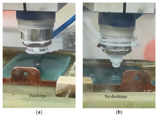
Figure 3.
Comparison diagram of the actual machining process. (a) Jet-MECDM (Discharge); (b) Jet-MECM (No discharge).
Figure 3a shows that discharge occurs inside the jet electrolytic flow injection and producing a superposition effect. Figure 3b shows that no discharge occurs in the jet and it is conventional electrolytic processing. Whether or not the discharge occurs, inevitably has a different effect on the machining effect. The experimental sample is the initial sample with low surface roughness (i.e., stainless steel workpiece), with the size specification of 70 × 50 × 1 mm3. To facilitate the measurement, the spacing between holes is set to be 4 mm, i.e., the distance between a and b is 4 mm, thus obtaining the machining dimensions of the mask as shown in Figure 4.
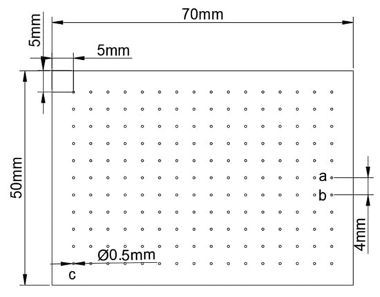
Figure 4.
Processing dimensions of the mask.
A blue oil mask with a thickness of 50 μm was prepared on the surface of the stainless steel workpiece using the photolithography process, as shown in Figure 5.
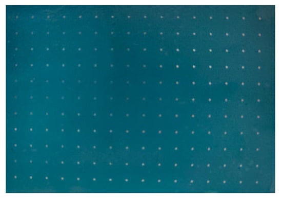
Figure 5.
Masked mirror stainless steel workpiece.
The corrosion factor (EF) is used to describe the fixed-domain nature of masked jet electrolytic processing, and is expressed as
In Equation (1) H is the crater depth, ΔD is the difference between the crater diameter and the mask hole diameter, D is the crater diameter and D0 is the mask hole diameter. The smaller ΔD is, the closer the crater diameter is to the mask hole diameter, and the larger H is, the deeper the crater depth is.
From Equation (1), it can be seen that the larger the EF value, the better the fixation and the better the definiteness, and the shape of the processed crater is closer to the skeletonized pattern; the smaller the E value, the worse the fixation. In the machining effect, the crater depth (H), diameter (D), material removal rate (MRR), and corrosion factor (EF) indicators are used to evaluate the machining effect.
3. Experimental Results and Discussion
The experiment is set up, the mask workpiece is prepared, and the differences between the two processes are analyzed through comparative experiments. Two types of processing are investigated: one is the stationary method, where the jet is sprayed right at the workpiece and the workpiece is processed through the mask hole. The second is a scanning and moving method, where the jet is scanned in a line at a certain speed, and the effect of nozzle movement on the shape of the workpiece is investigated.
3.1. Stationary Approach
As shown in Figure 2, the electrolyte is sprayed onto the workpiece in a jet state under a certain pressure, and the workpiece is machined by the jet through the mask hole in the mode of no feed on the X, Y, and Z axes, and a crater is formed at the location of the mask hole after a period of machining. The experimental conditions are shown in Table 2. NaNO3 electrolyte pressure is 0.03 MPa, and the concentration is 15%.
Table 2.
Specific parameters for single-well experimental conditions (Stationary Approach).
The experimental data on the depth H (depth) and diameter D (diameter) of the single holes (pits) machined by Jet-MECDM and Jet-MECM under the same machining conditions are shown in Table 3, with the units of depth H and width D in μm.
Table 3.
Depth and width of comparative experiments (Stationary Approach).
The experimental data on the depth H and diameter D of the hole (crater) are an important basis for the analysis of the efficiency of machining and whether the shape of the machining can be maintained.
As shown in Figure 6, the primary longitudinal axis represents the depth of a single hole (pit), and H (depth), and is represented by a bar graph. The secondary longitudinal axis represents the width of the single hole (crater), and D (diameter), and is represented by a line graph.
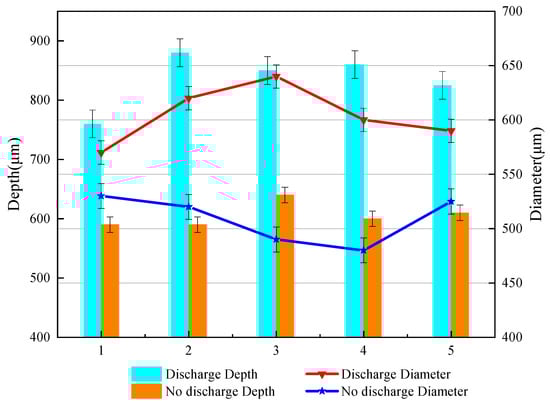
Figure 6.
Experimental diagram comparing the crater depth and width of the two models (Stationary Approach).
From Table 3 and Figure 6, we can see that (1) the Jet-MECDM method processes single-hole depths of between 760 and 880 μm, with a mean value of 835 μm. The Jet-MECM method processes single-hole depths of between 590 and 640 μm, with a mean value of 606 μm. The difference between the two means is 229 μm, and the Jet-MECDM contribution to depth increases by 38%. (2) The Jet-MECDM method processes hole widths between 570 and 640 μm, with a mean value of 604 μm. The Jet-MECM method processes hole widths between 480 and 530 μm, with a mean value of 509 μm. The difference between the two mean values is 95 μm, and the contribution of Jet-MECDM to width increases by 18%, compared to Jet-MECM. (3) Jet-MECDM contributes more to depth (38%) than width (18%), when compared to Jet-MECM. The aim of using the mask is to constrain the width, i.e., to obtain a greater increase in material removal, as far as the processed morphology allows.
To further investigate its machined morphology, a single hole was observed in 3D using a laser scanning confocal microscope, as shown in Figure 7.
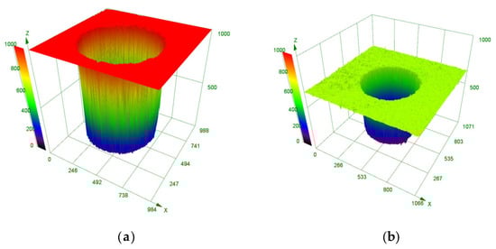
Figure 7.
Contrasting experimental machining 3D morphology. (a) Jet-MECDM machining 3D profile; (b) Jet-MECM machining 3D profile.
As can be seen from Figure 7, the shape of the single hole machined by the Jet-MECDM method is as regular as that of the single hole machined by the Jet-MECM method, and the inner wall of the single hole machined by both is equally smooth. To investigate the role of the mask as a constraint, the single hole with the mask was observed in 2D using a laser scanning confocal microscope, as shown in Figure 8.
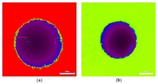
Figure 8.
Comparison of experimental machined 2D profiles. (a) Jet-MECDM machining 2D profile; (b) Jet-MECM machining 2D profile.
As can be seen in Figure 8, the Jet-MECDM does not have any significant damage to the mask due to the discharge effect, and the mask is well constrained. The comparison in Figure 8 also shows that the color of the bottom of the Jet-MECM hole is not consistent, indicating a large deviation in the bottom morphological profile. This is further confirmed by the side measurements of the hole cross-sections for both machining methods, as shown in Figure 9.
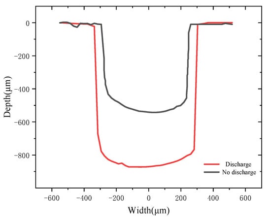
Figure 9.
Single-hole (crater) depth and width measurement diagram (Stationary Approach).
As can be seen from Figure 9, the shape of the Jet-MECDM machined single hole (pit) is close to cylindrical, while the shape of the Jet-MECM machined single hole (pit) is closer to an inverted trapezoid. The steepness of the inner wall of the Jet-MECDM machined single hole (pit) is steeper and almost vertical, with less side etching. In contrast, the Jet-MECM process has a different amount of lateral corrosion at the top and bottom of the single hole (crater), creating an inverted trapezoid shape with a large top and a small bottom. Both Jet-MECDM and Jet-MECM process the bottom of the single hole (pit) without the island effect of normal mask electrolytic processing. However, the bottom of the Jet-MECDM process is flatter.
3.2. Scanning Movement Method
As shown in Figure 2, the Y and Z axes are not fed, the X axis moves at a certain speed of motion (scanning), and the parameters of the experimental conditions are shown in Table 4. NaNO3 electrolyte pressure is 0.03 MPa, and the concentration is 15%.
Table 4.
Specific parameters for single-well experimental conditions (Scanning Movement).
The experimental data on the depth H (depth) and width D (diameter) of the single holes (pits) machined by Jet-MECDM and Jet-MECM under the same conditions are shown in Table 5, with the units of depth H and width D being μm.
Table 5.
Depth and width of comparative experiments (Scanning Movement).
The experimental data for the depth H and width D of the holes (pits) are an important basis for the analysis of machining efficiency and quality. For ease of observation, the experimental data in Table 5 is plotted as a relationship, as shown in Figure 10.
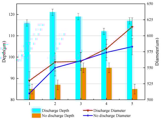
Figure 10.
Experimental diagram comparing the crater depth and width of the two models (Scanning Movement).
As shown in Figure 10, the primary longitudinal axis represents the hole (pit) depth H (depth) and is represented by a bar graph. The secondary longitudinal axis represents the width D (diameter) of a single hole (pit), and is represented by a line graph.
- (1)
- The Jet-MECDM method processes single-hole depths between 112 and 121 μm, with a mean value of 117 μm. The Jet-MECM method processes single-hole depths between 85 and 95 μm, with a mean value of 90 μm. The difference between the two means is 27 μm, with Jet-MECDM contributing 30% more to depth than Jet-MECM.
- (2)
- The Jet-MECDM method processes single-hole widths between 530 and 614 μm, with a mean value of 569 μm. The Jet-MECM method processes single-hole widths between 510 and 583 μm, with a mean value of 556 μm. The difference between the two means is 13 μm, and the contribution of Jet-MECDM to width increases by 2% over Jet-MECM.
- (3)
- A comparison of Jet-MECDM and Jet-MECM in the scanned condition reveals that Jet-MECDM machining depths increase and material removal rates improve for almost equal amounts of side etching.
The single-hole (crater) depth and width measurement diagram is shown in Figure 11.
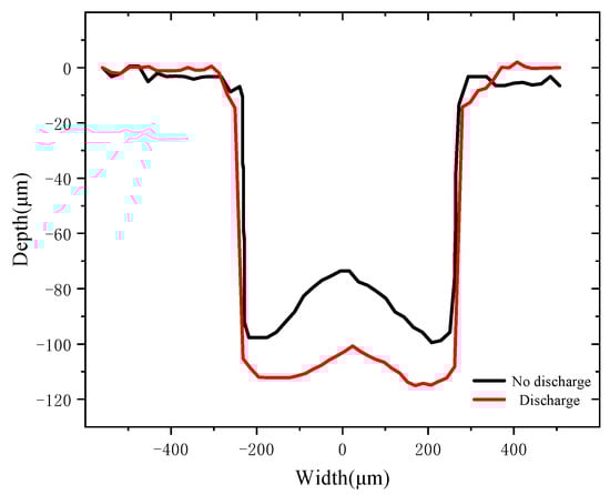
Figure 11.
Single-hole (crater) depth and width measurement diagram (Scanning Movement).
From Figure 11, it can be seen that the inner wall of the Jet-MECDM machined single hole (pit) is steeper and more vertical, and the island of the machined single hole (pit) is 15 μm higher. It can be seen that the side etching of the upper and lower part of the Jet-MECM machined single hole (pit) is different, and the island of the machined single hole (pit) is 30 μm higher, the island of the normal mask electrolytic machining. The island effect is smaller in Jet-MECDM than in Jet-MECM, and the bottom is flatter, resulting in a better shape.
4. Conclusions
This paper investigates the experimental electrolytic processing of discharge-assisted jet masks, and draws the following conclusions.
A comparison experiment between Jet-MECDM and Jet-MECM was carried out, and the results showed that
- (1)
- The experimental setup for jet electrolytic processing was set up to complete the preparation of mask workpieces. Under other processing conditions, the use of metal nozzles produced a discharge compound effect, while the use of plastic nozzles did not.
- (2)
- In the stationary method, Jet-MECDM increases the contribution to depth by 38% and the contribution to width by 18% over Jet-MECM, i.e., the machining efficiency is improved to a greater extent than the machined shape allows. The bottom of the single hole (crater) machined by both methods does not show the island effect of normal electrolytic machining.
- (3)
- In the scanning movement method, Jet-MECDM contributes 30% more to the depth and 2% more to the width than Jet-MECM, i.e., the width is essentially the same but the depth increases significantly and the machining efficiency improves dramatically. The island effect of normal electrolytic machining occurs at the bottom of single holes (pits) machined by both methods, with the former having less island effect than the latter, a smoother bottom, and a better-machined shape.
Using the Jet-MECDM process, jet electrolysis is used throughout the machining process, which can improve the machining accuracy, while the discharge effect can increase the material removal capacity and effectively improve the depth-to-width ratio (effectively improving the machining efficiency). In the next stage, the process will be studied in depth in terms of different masks, different workpieces, and different processing voltages.
Author Contributions
Conceptualization, C.C.; methodology, C.C.; software, C.C.; validation, C.C., and S.W.; formal analysis, C.C. and T.Z.; investigation, Y.W.; resources, C.C.; data curation, X.S. and F.M.; writing—original draft preparation, C.C.; writing—review and editing, S.W.; visualization, C.C.; supervision, S.W.; project administration, S.W.; funding acquisition, C.C. All authors have read and agreed to the published version of the manuscript.
Funding
This research was funded by the National Natural Science Foundation of China (grant NO. 52075104), and Guangzhou Higher Education Quality and Reform Project (2023CJRHJD002).
Institutional Review Board Statement
Not applicable.
Informed Consent Statement
Not applicable.
Data Availability Statement
Data are contained within the article.
Conflicts of Interest
The authors declare no conflict of interest.
References
- Kawanaka, T.; Kunieda, M. Mirror-Like Finishing by Electrolyte Jet Machining. CIRP Ann. 2015, 64, 237–240. [Google Scholar] [CrossRef]
- Zhang, X.; Song, X.; Ming, P.; Li, X.; Zeng, Y.; Cai, J. The Effect of Electrolytic Jet Orientation on Machining Characteristics in Jet Electrochemical Machining. Micromachines 2019, 10, 404. [Google Scholar] [CrossRef] [PubMed]
- Fan, G.; Chen, X.; Saxena, K.K.; Liu, J.; Guo, Z. Jet Electrochemical Micromachining of Micro-Grooves with Conductive- Masked Porous Cathode. Micromachines 2020, 11, 557. [Google Scholar] [CrossRef] [PubMed]
- Liu, Y.; Qu, N. Investigation on the performance of macro electrochemical machining of the end face of cylindrical parts. Int. J. Mech. Sci. 2020, 169, 105333. [Google Scholar] [CrossRef]
- Fu, X.Q.; Kang, M.; Zheng, Q.Y. Research on Flow Field Simulation and Experiment of Numerical Control Electrochemical Machining. key Eng. Mater. 2011, 458, 63–68. [Google Scholar]
- Hinduja, S.; Pattavanitch, J. Experimental and numerical investigations in electro-chemical milling. CIRP J. Manuf. Sci. Technol. 2016, 12, 79–89. [Google Scholar] [CrossRef]
- Hackert-Oschätzchen, M.; Meichsner, G.; Zinecker, M.; Martin, A.; Schubert, A. Micromachining with continuous electrolytic free jet. Precis. Eng. 2012, 36, 612–619. [Google Scholar] [CrossRef]
- Mitchell-Smith, J.; Speidel, A.; Clare, A.T. Advancing electrochemical jet methods through manipulation of the angle of address. J. Mater. Process. Technol. 2018, 255, 364–372. [Google Scholar] [CrossRef]
- Mitchell-Smith, J.; Speidel, A.; Gaskell, J.; Clare, A.T. Energy distribution modulation by mechanical design for electrochemical jet processing techniques. Int. J. Mach. Tools Manuf. 2017, 122, 32–46. [Google Scholar] [CrossRef]
- Chu, W.S.; Kim, C.S.; Lee, H.T.; Choi, J.O.; Park, J.I.; Song, J.H.; Jang, K.H.; Ahn, S.H. Hybrid manufacturing in micro/nanoscale: A review. Int. J. Precis. Eng. Manuf. Green Technol. 2014, 1, 75–92. [Google Scholar] [CrossRef]
- Singh, T.; Dvivedi, A. Developments in electrochemical discharge machining: A review on electrochemical discharge machining, process variants and their hybrid methods. Int. J. Mach. Tools Manuf. 2016, 105, 1–13. [Google Scholar] [CrossRef]
- Singh, T.; Appalanaidu, B.; Dvivedi, A. Improvement in energy channelization behaviour during micro hole formation in Y-SZ ceramic with magnetic. Measurement 2022, 194, 111079. [Google Scholar] [CrossRef]
- Kim, D.J.; Ahn, Y.; Lee, S.H.; Kim, Y.K. Voltage pulse frequency and duty ratio effects in an electrochemical discharge microdrilling process of Pyrex glass. Int. J. Mach. Tools Manuf. 2006, 46, 1064–1647. [Google Scholar] [CrossRef]
- Kobayashi, F. Electrochemical discharge drilling methode. Pantent JP. 1997, 32, 64–69. [Google Scholar]
- Liu, J.W.; Yue, T.M.; Guo, Z.N. An analysis of the discharge mechanism in electrochemical discharge machining of particulate reinforced metal matrix. Int. J. Mach. Tools Manufacture. 2010, 50, 86–96. [Google Scholar] [CrossRef]
- Yu, W. Experimental study on micro-structure machining by electrohydraulic beam. Master’s Thesis, Dalian University of Technology, Dalian, China, 2013. [Google Scholar]
- Cui, J. Basic Law and Simulation Research of Micro EDM. Ph.D. Thesis, Harbin Institute of Technology, Harbin, China, 2007. [Google Scholar]
- Liu, H.; Xieeryazidan, A. Study of Gas Film Characteristics in Electrochemical Discharge Machining and Their Effectson Discharge Energy Distribution. Micromachines 2023, 14, 1079. [Google Scholar] [CrossRef]
- Chuang, M.-C.; Jan, C.-M.; Wang, Y.-J.; Hsu, Y.-L. Intelligent Monitoring and Compensation between EDM and ECM. Appl. Sci. 2023, 13, 927. [Google Scholar] [CrossRef]
- Sambathkumar, S.; Arunagirinathan, R.S. A Simple Technique for the Precise Establishment of the Working Gap in an Electrochemical Discharge Machining Process and Some Experimental Results Thereof. Micromachines 2022, 13, 1367. [Google Scholar] [CrossRef]
- Zhao, R.; Huang, L.; Zhao, H.; Cao, Y.; Tian, W.; Wang, N. Study of Mask Electrochemical Machining for Ring Narrow Groove under the Action of Multiple Physical Fields. Coatings 2022, 12, 605. [Google Scholar] [CrossRef]
- Zhan, S.; Zhao, Y. Plasma-assisted electrochemical machining of microtools and microstructures. Int. J. Mach. Tools Manuf. 2020, 156, 103596. [Google Scholar] [CrossRef]
- Jui, S.K.; Kamaraj, A.B.; Sundaram, M.M. High aspect ratio micromachining of glass by electrochemical discharge machining (ECDM). J. Manuf. Process. 2013, 15, 460–466. [Google Scholar] [CrossRef]
- Wang, T.; Liu, Y.; Wang, K.; Lv, Z. Investigation on a sustainable composite method of glass microstructures fabrication—Electrochemical discharge milling and grinding (ECDM-G). J. Clean. Prod. 2023, 387, 135788. [Google Scholar] [CrossRef]
Disclaimer/Publisher’s Note: The statements, opinions and data contained in all publications are solely those of the individual author(s) and contributor(s) and not of MDPI and/or the editor(s). MDPI and/or the editor(s) disclaim responsibility for any injury to people or property resulting from any ideas, methods, instructions or products referred to in the content. |
© 2023 by the authors. Licensee MDPI, Basel, Switzerland. This article is an open access article distributed under the terms and conditions of the Creative Commons Attribution (CC BY) license (https://creativecommons.org/licenses/by/4.0/).