Abstract
Atmospheric pressure plasma (AP) treatment, using an open-air jet of ionized CO2, N2, or air, was applied to AZ91D Mg alloy surfaces to investigate its effects on primer coating adhesion and corrosion resistance. The CO2 and air AP treatments formed an O- and C-rich surface layer (Mg-O-C) consisting of agglomerated nanoparticles and pits with a depth of a few microns and increasing the surface roughness by 6–8 times compared with the reference 600 grit-finished surface. Then, three commercial primers, zinc phosphate (ZnP), chromate-containing epoxy, and MIL23377, were applied on the treated surfaces to evaluate the corrosion resistance associated with the coating adhesion. Microscopic analysis demonstrated stronger interlocking between the primer layer and the nano-/microrough Mg-O-C surface compared to the untreated (600 grit-finished) surfaces, indicating improved coating adhesion and corrosion resistance. Crosscut tests of the MIL23377 primer on the CO2 and air AP-treated surfaces showed the highest level of adhesion, ASTM class 5B. Salt spray corrosion tests showed that after 8 days of exposure, the primer coatings on air AP-treated surfaces had corrosion areas that were more than four times smaller than that of the 600 grit-finished surface. The N2 AP treatment showed similar adhesion enhancement. The preliminary operation expenses for AP treatment using CO2, N2, and air were estimated at USD 30.62, USD 35.45, and USD 29.75 (from an air cylinder)/USD 0.66 (from an air compressor) per m2, respectively.
1. Introduction
Magnesium alloys can be used to construct various high-volume structural materials for lightweight engineered systems with improved fuel economics and zero carbon emissions [1,2,3]. Although progress has been made in the development of magnesium (Mg) alloys, their intrinsic susceptibility to corrosion has limited their application in some industries, such as their use for a few parts of aerospace and automobile structures [4,5,6,7]. Protective coatings are considered the most cost-effective way to improve the corrosion resistance of Mg alloys without diminishing their benefits to the larger structure or the system’s mechanical properties. The coatings also benefit from fast process time, low cost, and good application on various metal surfaces. Various coatings, such as electrochemical conversion [8,9], anodizing [10,11], electroplating [12], cold spray [13,14], superhydrophobic coating [15,16,17,18], and organic primers [19,20], have been investigated for the protection of Mg alloy surfaces. The performance of a protective coating is greatly influenced by its adhesion to the substrate material. Additionally, a single coating is insufficient to protect a Mg alloy surface, particularly on an automotive body; therefore, multilayer coating schemes via a series of wet chemical pretreatments have been proposed to reliably protect Mg [21].
Selecting the proper protective coating to apply on a bare Mg alloy is challenging because a traditional polymeric coating (e.g., pure epoxy) does not provide good adhesion to Mg alloys, and corrosion may be accelerated if the coating is physically damaged [19]. For these reasons, metal particle composite coating matrixes (e.g., Al-/Mg-rich primer) have been investigated to provide the cathodic protection and improve barrier effects [19,20]. The particles selected for the composite matrixes were limited to a few active metals, such as pure Mg and Al, because of the internal galvanic corrosion caused by the second phase or impurities. To promote primer coating adhesion, the surface must be cleaned properly before applying the coating to remove impurities, oil, and other organic carbons. Chemical treatments using organic solvents, such as isopropyl alcohol, acetone, and toluene, are typically used to clean the surfaces in industrial applications, but these solvents have problems related to solvent inflammability and chemical waste. Physical surface treatments, such as sand blasting, wire brushing, scarping, and chipping, can modify the surface roughness to improve the mechanical interlocking between the coating and surface, enabling a stronger bond. However, these methods usually produce process waste and severely damage the treated surface [22].
Surface modification by atmospheric pressure plasma (AP) treatment has been considered for the improvement of coating adhesion on metal and polymeric materials because it can treat the entire surface uniformly and is environmentally friendly if the appropriate gases are chosen [23,24,25,26,27]. Currently, the AP technique is being industrialized in large-scale deployments, such as that of an automated in-line continuous system to remove coatings of material (e.g., a layer, film, or paint) from the substrate surfaces for a rapid, low-cost, open-air surface cleaning process [28,29,30]. AP treatment generates a high-velocity flow of nonthermal plasma, chemically active gas species (i.e., ions and electrons), and electronically excited species using only electricity and compressed air or other gases as the feeds of operation. The interaction of all these plasma species with a surface can improve the adhesion bonding of polymer films by creating surface functional groups and topography [25,27]. As is the case when it is applied to polymeric surfaces. AP treatment on Mg surfaces may improve coating adhesion through surface cleaning, surface chemistry, and topography changes for the strong chemical bonding and physical interlocking of coating materials. Moreover, we found that CO2 AP treatment forms an oxygen and carbon-rich corrosion resistance layer on pure Mg, which may be applicable to Mg alloy to protect the surface [31]. In this study, AP treatments with CO2, N2, and air were used on AZ91D Mg alloy before primer coatings were applied on the treated surface to investigate their effects on coating adhesion. We report that AP treatments with CO2 or air form a nano-/microscale Mg-O-C particle agglomerated layer when operated at a high gas flow rate and scan rate (i.e., 70 standard liters per minute with a 762 cm/min scan rate) with multiple swings, which improve the adhesion of primer coatings to the surface. AP treatments with CO2 or air usually form nano-/microscale Mg-O-C particle agglomerated layers, improving the adhesion of primer coatings to the surface. Standard coating adhesion tests and a salt spray test were performed to evaluate the enhanced coating adhesion and corrosion resistance on the plasma-treated surfaces compared with the coatings on 600 grit-finished surfaces with no treatment. Additionally, a corrosion resistance test was performed on the treated surfaces to evaluate their corrosion susceptibility. However, the current operation parameter and Mg alloy type (i.e., cast AZ91D) showed no benefit in forming a corrosion-resistant layer. Finally, a preliminary cost analysis for operation expense was performed to assess the benefits of AP plasma treatments for improved coating adhesion. There are only a limited number of literature reports on the impact of AP treatments on coating adhesion for Mg alloys. Here, we show that the adhesion of commercial primer coatings and their corrosion resistance can be significantly enhanced through a single-step AP treatment. Our performance and operating cost analysis also indicates that air AP treatment has the potential to be a cost-effective way to protect Mg alloys, compared with CO2 and N2 AP treatments.
2. Materials and Methods
2.1. Samples
A commercial cast AZ91D was obtained from Advanced Magnesium Alloys Corporation (Anderson, IN, USA). The commercial cast high-pressure casted AZ91D was obtained from Magnesium Elektron North America, Madison, IL, USA. Test samples of 2.5 cm × 2.5 cm in size and 1–1.5 mm in thickness were prepared by electric discharge machining of the raw AZ91D cast. The test samples were wet-ground with 600 grit SiC paper, cleaned with deionized water, and dried with an air stream.
2.2. CO2/Air Atmospheric Pressure Plasma Treatment of AZ91D Substrate
The atmospheric pressure plasma treatment was performed using a PlasmaBlast (Model 7000, Input power 208–240 VAC, 50–60 Hz, Atmospheric Plasma Solutions Inc., Cary, NC, USA) and an RD1004 jet (Plasmatreat USA Inc., Input power 510–643 W, Hayward, CA, USA) [32]. The treatment was performed in a working chamber equipped with a robotic arm for 3D surface treatments and an exhaust and filtration system. A high-velocity flow of chemically active gas radicals exited the nozzle tip to form a plasma jet plume, as shown in Figure 1 and Figure S1 in Supplementary Information. The robotic stage and plasma nozzle were controlled by three stepper motors and three rack and pinion drives that could move in the x (forward), y (side), and z (height) directions. In the previous work [31], various plasma operation conditions, such as nozzle height, gas flowrate, spacing, scan rate, and swing number, were tested to uniformly treat Mg surfaces, resulting in the maximizing of the functionality (i.e., corrosion resistance and wettability). The optimized process parameter was used for a baseline condition. Various plasma operation conditions were tested to enhance coating adhesion. For example, CO2 AP was generated by 100% CO2 gas passed through a nozzle at a flow rate of 70 SLPM, and the nozzle swung through the sample surface with a 0.38 cm height and 0.06 cm spacing with a 762 cm/min scan rate. The swing number increased to intensify the CO2 AP effect. The CO2 atmospheric pressure plasma treatment was performed in a custom-designed, CO2-filled gas chamber, whereas the air atmospheric pressure plasma treatments were performed in the open air with the same operating conditions. Finally, a single swing N2 AP treatment was evaluated in the open air. The N2 AP was generated by 100% N2 gas passed through a nozzle at flow rates of 33–45 SLPM, and the nozzle swung through the sample surface with a 0.4 cm height and 0.06 cm spacing at a scan rate from 6 cm/min to 150 cm/min.
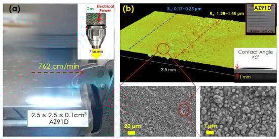
Figure 1.
(a) A snapshot of atmospheric pressure plasma treatment on AZ91D (2.5 cm × 2.5 cm × 0.1 cm) during a scanning at 762 cm/min. The inset is a plasma nozzle with a scheme of the plasma plume generation and (b) optical surface topography of CO2 AP-treated AZ91D with SEM images. The upper inset photo in (b) shows the CO2 AP treatment on a 2.5 cm × 2.5 cm × 0.1 cm AZ91D coupon treated with 5 swings spaced 0.24 cm apart. The lower inset image in (b) shows a water contact angle measurement on the surface. The size of the water droplet is 10 μL.
2.3. Primer Coatings
Commercially available zinc phosphate primer (16-897 SEYMOUR, Yellow, 12 oz) and chromate-containing 2K epoxy primer (Hard Hat, Rust-Oleum, Vernon Hills, IL, USA) were used to coat the AZ91D surface. After activation (e.g., pulling a trigger and shaking the container), the primers were sprayed on the AZ91D specimens (2.5 cm × 2.5 cm) from a distance of ~30 cm for 30 s. Experimental and reference specimens were placed together side by side for uniform coating. After coating, the samples were dried overnight at room temperature.
Military epoxy primer (MIL23377) was also applied to AZ91D surfaces to evaluate the coating adhesion and corrosion protection. First, the MIL 23377 primer solution was stirred with an automated mixer. Next, the same volume of activator was added to the stirred primer, continuously mixed for 10 min, and allowed to sit for the required amount of time (e.g., 30 min for 60 mL). Temperature and humidity were measured throughout the coating process to ensure that the acceptable limits (10–40 °C and <65% humidity) were met. The coating specimens (i.e., AZ91D) were prepared by cleaning the surface with a reagent, which was a mixture of alcohols that included ethanol and isopropyl. The MIL23377 primer coating was applied with a high-volume, low-pressure spray gun. The pressure was maintained at 1.379 × 10⁵ Pa during each application. Two or three passes were applied with each application, depending on how well the coating adhered to the surface. The coating was air-cured for 7 days at room temperature after each application. After the coating was fully cured, its thickness was measured with a Positector 6000 coating thickness gauge. The average thickness of the coating on the total specimens was 44.0 ± 5.2 μm (n = 22).
2.4. Characterization of Materials
AP-treated sample surfaces were analyzed by scanning electron microscopy (SEM, Zeiss Merlin FE-SEM) with energy-dispersive X-ray spectroscopy (EDS), an optical profilometer, X-ray photoelectron spectroscopy (XPS, Thermo Fisher Scientific, Waltham, MA, USA, K-Alpha X-ray Photoelectron Spectrometer), X-ray diffraction (XRD), and cross-section scanning transmission electron microscopy (STEM, 300 kV Aberration-corrected S/TEM-EELS, FEI Titan, Stanford Nano Shared Facilities, Stanford, CA, USA). XRD measurements were conducted on a PANalytical X’Pert Pro MPD equipped with an X’Celerator solid-state detector. For the XRD measurements, the X-ray beam was generated at 45 kV/40 mA, and the X-ray beam wavelength was set at l = 1.5418 Å (Cu Kα radiation). The step size (D2q) was 0.016°, and the exposure time at each step was 40 s. XPS depth profiling analyses were conducted with an EX06 Ar ion gun operated at 2000 eV and rastered over a 2 mm × 4 mm area. Water contact angles were measured by a drop shape analyzer (KRUSS, Chaussee, Germany), employing a water droplet volume of 8~10 μL.
2.5. Corrosion Evaluation
Potentiodynamic polarization measurements were conducted for the 600 grit-finished and AP-treated AZ91D samples, i.e., working electrodes, with the exposed area of 0.833 cm2 (Ø = 10.3 mm) prepared by insulation tape masking. A reference saturated calomel electrode (SCE) and a Pt plate counter electrode with ~5 cm2 of surface area were used in a 3.5 wt.% NaCl solution. After each Mg sample rested at open-circuit potential (OCP) for 50–60 min, potentiodynamic polarization was performed at a rate of 1 mV·s−1 in two potential windows: −2.1 to −1.1 VSCE and −2.25 to −0.95 VSCE. Electrochemical impedance spectroscopy (EIS) was also performed to assess corrosion behavior with increasing immersion time in 3.5 wt.% NaCl solution. The OCP was measured for 1 h before the first EIS measurement for the first impedance data. Subsequent EIS measurements were taken for the same samples at longer immersion times. The frequency window was 200 kHz to 7 mHz, and the amplitude was ±10 mV with respect to the last OCP value. The impedance data were analyzed using commercial computer software (ZView, Scribner, Southern Pines, NC, USA) to determine the key resistance values for the corrosion evaluation. All the electrochemical measurements were taken at room temperature in the open air.
Salt spray exposure tests were performed per ASTM B117 for several primer-coated samples in a salt fog chamber (Auto Technology, Strongsville, OH, USA) [33]. The coated samples were placed at an angle of ~60° on two loading racks and evenly distanced from the fog tower for uniform salt spray exposure. Visual inspection and photo imaging of the coated samples were performed before, intermittently during, and after the exposure.
2.6. Preliminary Cost Estimation
The operation expense of the AP treatment per square meter was calculated as
where is the cost of the materials (i.e., gases) and is the total electricity cost. These costs were calculated as
The area scan rate is how fast a plasma nozzle sweeps a square meter, which was calculated by multiplying (linear) scan rate (cm/min) by scan spacing (cm) and 10−4 to be in m2/min. The area scan rate and other variables are listed in Table 1. The electric rate was 0.12 USD/kWh (commercial GSA-1) [34]; the price of CO2 was 1.04 USD/kg (industrial grade, size 200) [35]; the price of N2 was 1.81 USD/kg (industrial grade, size 300) [36]; and the air price was 3.28 USD/kg (breathing grade, size 300) [37]. The air source can be replaced with a filtered air compressor (e.g., Ingersoll Rand air compressor). For this case, only additional electricity consumption was considered, which is calculated by multiplying the compressor power per filtered air flow rate, 6.11 W/SLPM [38], by the air flow rate (SLPM) and then plugging it into Equation (3).

Table 1.
Variables of treatment and conditions.
3. Results and Discussion
3.1. CO2 Atmospheric Plasma Treatment
The AP treatment using CO2 feed gas formed highly wettable nano-/microstructured surfaces, which were expected to enhance the adhesion of the primer coatings. Figure 1a shows the discharging AP plume moving across an AZ91D surface in preparation for primer coating. After the CO2 AP treatment, all the treated AZ91D samples, as shown in the inset of Figure 1b, exhibited water contact angles of less than 10°, which were slightly lower than those of the fresh 600 grit-finished surfaces [See Table S1 in Supplementary Information]. The CO2 AP created nano-/microscale roughness on the surface, as shown in Figure 1b. Cavities with a 10–20 μm diameter were formed along the CO2 AP beam alignment. The CO2 AP jet ablated a portion of the Mg surface at the direct exposure area, and the ablated Mg species were deposited on the surface around the cavities as nanoparticle agglomerations. The microsurface roughness (Ra) was 1.28–1.45 μm, which was 6–8 times rougher than that of the reference surface (i.e., the 600 grit-finished surface, Ra = 0.17–0.25 μm). The baseline operational parameters (i.e., scanning at 762 cm/min and multiple swings spaced 0.24 cm apart) were optimized in the previous work [31]. For instance, a single swing and low scan rates were unable to form a uniform rough surface on the Mg surface.
A C- and O-rich surface layer formed on the CO2 AP-treated AZ91D. Chemically active CO2 plasma molecules were reported to react with MgO nanoparticle surfaces and then form carbonated layers in the CO2-enriched environment [31]. The formation of MgCO3 was thermodynamically favored, and the MgO particles had diverse basic sites where the acidic CO2 molecules chemically and/or physically adsorbed on the surface, resulting in various carbonate surface species, including bicarbonate, bidentate, and unidentate carbonates [39]. The SEM-EDS images, as shown in Figure 2a, indicate that the nanoparticle-agglomerated area of the treated surface had higher C and O contents than the surrounding cavities. This suggests that the MgO adsorbed CO2 from the multiple CO2 plasma swings in the CO2-rich environment. The XRD measurements in Figure 2b confirm the formation of new crystalline phases at ~43°, which can be attributed to the hexagonal phase of MgCO3 and/or MgO [31].
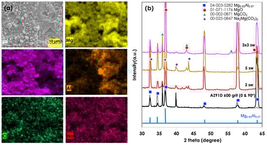
Figure 2.
(a) SEM-EDS images of the CO2 AP-treated AZ91D (5 swings) and (b) XRD patterns of various CO2 AP-treated AZ91D specimens treated with different swings and 600 grit-finished reference. XRD patterns of untreated Mg were measured at two angles (0° and 90°) to avoid the crystalline directional effect. The 3 × 3 sw denotes 3 cross-swings (i.e., 3 horizontal swings and 3 vertical swings).
The XPS depth profiling of CO2 AP-treated AZ91D, as shown in Figure 3 and Table 2, indicated that the CO2 AP treatment left a layer of significant carbon (C–C) and carbonate (-CO3), formed on top of an existing thick MgO layer. Moreover, ~9 atom % of carbon existed after 16,000 s of sputtering.
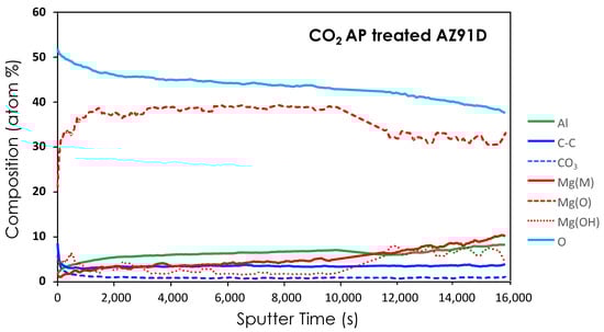
Figure 3.
XPS depth profiling of chemical components of the CO2 AP-treated AZ91D.
Table 2.
Surface composition (atom %) of corresponding XPS depth profiling.
3.2. Enhancement of Adhesion Bonding
The CO2 AP-treated surface with primer coatings substantially enhanced corrosion resistance, as described in the following results. Figure 4a shows that the ZnP and epoxy primer coatings were well applied on both the 600 grit-finished surfaces and the CO2 AP-treated surfaces. No significant difference was found on either of the coatings. The electrochemical polarization curves, as shown in Figure 4b,c, indicated that the ZnP and epoxy primer coatings on the CO2 AP-treated (i.e., with five swings) and the 600 grit-finished surfaces, even after 119 h and 150 h in 3.5% NaCl, significantly reduced the anodic and cathodic currents compared to those of the uncoated AZ91D. It was also noted that the current was even lower with the CO2 AP treatment in the epoxy-coated samples. Presumably, this was due to a reduction in the NaCl solution permeation through the epoxy primer coating on the CO2 AP-treated AZ91D. After the completion of electrochemical measurements, both the ZnP and the epoxy primers were easily removed with the masking tape from the reference (600 grit-finished) surface, whereas the primer coatings on the CO2 AP-treated surfaces were still intact (see Figure 4d,e). To further investigate the adhesion behavior of the CO2 AP-treated surface, a second spray coating of epoxy primer with ~50 μm thickness was applied on both the CO2 AP-treated surfaces with five swings and the reference surface.
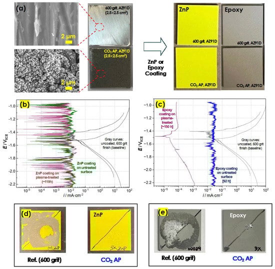
Figure 4.
(a) SEM and photo image of 600 grit-treated and CO2 AP-treated AZ91D (5 swings, spaced 0.06 cm apart) and their ZnP primer coating; (b,c) potentiodynamic polarization measurements of the ZnP primer and the epoxy primer coated on CO2 AP-treated AZ91D 600 grit-finished reference AZ91D surfaces in a 3.5 wt.% NaCl solution after >90 h immersion. The inset photo shows the ZnP coating on a 2.5 cm × 2.5 cm AZ91D coupon. Also shown are two polarization curves of uncoated AZ91D surface with 600 grit finish. (d,e) The appearance of yellow ZnP and gray epoxy primers coated AZ91D samples (with 600 grit finish and CO2 AP treatment) after electrochemical evaluation in 3.5% NaCl solution for extended immersion time longer than 119 h. Coatings on 600 grit-finished surfaces were easily removed.
Next, a through-coatings scribe was prepared for each primer-coated sample to accelerate corrosion in a NaCl solution. After 96 h, a significant amount of the epoxy coating was removed from the reference surface by corrosion through the cuts, whereas the epoxy coating on the CO2 AP-treated surface was intact with minimal corrosion, suggesting that the corrosion in the exposed cut was limited because of strong adhesion bonding between the epoxy coating and the treated surface. Figure 5 shows cross-sections of the epoxy primer layers on the CO2 AP-treated and 600 grit-finished AZ91D surfaces. Figure 5b clearly indicates that the coating strongly adhered to the CO2 AP-treated surface even after the corrosion exposure. In contrast, Figure 5a shows a gap between the epoxy primer layer and the 600 grit-finished reference surface, indicating relatively weak adhesion. The interface between the epoxy layer and the CO2 AP-treated surface shows that the Mg-O-C-rich layer of the Mg alloy surface interlocked with the primer layer.
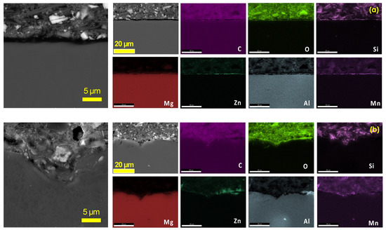
Figure 5.
Cross-sectional SEM-EDS characterization of epoxy primer coatings on (a) 600 grit-finished AZ91D surfaces and (b) CO2 AP-treated AZ91D surfaces.
The third primer coatings (i.e., MIL23377) were applied on the CO2 AP-treated and reference surfaces. The measured thicknesses of the coatings on the CO2 AP-treated and the 600 grit-finished reference surfaces were 43.0 ± 2.8 μm (n = 5) and 43.3 ± 4.6 μm (n = 5), respectively. Crosshatch adhesion tests were conducted according to ASTM D3359 to quantify the coating adhesion. Figure 6a shows that both the CO2 AP specimen and the reference specimen had a fractional rate of ASTM class 5B, the highest coating adhesion rating. Then, a long-term salt spray test was also conducted to determine the coating adhesion and corrosion resistance. Figure 6b shows that the corrosion area of the CO2 AP specimen, by plan view visual inspection, was much smaller than that of the reference specimen, suggesting that the nano-/microrough Mg-O-C layer on AZ91D significantly enhanced the adhesive bonding of the primer, thereby mitigating corrosion.
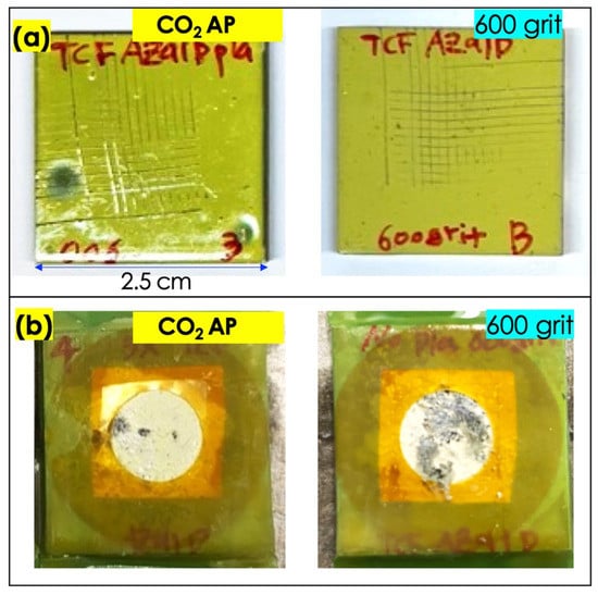
Figure 6.
(a) The MIL23377 primer-coated, 2.5 cm × 2.5 cm AZ91D sample treated with 5 swings of CO2 AP spaced 0.06 cm apart after the coating adhesion test. (b) MIL23377 primer-coated samples (2.5 × 2.5 cm) after the 8-day salt spray test. The exposed area is 0.833 cm2 (Ø = 10.3 mm). The photo images were taken after the samples were rinsed with water.
Our previous work demonstrated that CO2 AP treatment on commercial pure Mg enhances corrosion resistance by forming a Mg-O-C layer with a thickness of a few microns [31]. However, the work described in this paper—although similar to our previous work, in which five swings with three different spacings were also used—did not show the same improved corrosion resistance for the AZ91D specimen compared with the untreated surface (see Figure S2 in Supplementary Information). Because of the alloying elements (i.e., ~9 wt.% Al and ~1 wt.% Zn), the thickness and coverage of the formed Mg-O-C-rich layer on AZ91D may have been insufficient for it to act as a protective layer, as it did for high purity Mg in the present operation.
3.3. Air Atmospheric Plasma Treatment
The ability of AP treatment to enhance coating adhesion was further evaluated using an inexpensive air AP treatment, which used a high-pressure air compressor. The air AP treatment was conducted with the same operation parameters as those of the CO2 AP treatment on specimens with areas from 2.5 cm × 2.5 cm to 5 cm × 7.5 cm, as shown in Figure 7a. The treated surfaces were fully wettable with water droplets, indicating that the treated surfaces were hydrophilic. Figure 7b shows that the air AP treatment developed a rough surface morphology with O- and C-rich particle layers, which were very similar to the layers on the CO2 AP-treated surfaces. Deep craters and cavities were observed at the direct plasma jet exposure area, where the O and C contents in the craters and cavities were lower than those in the flat areas (i.e., everywhere that was not a crater or cavity). As occurred during the CO2 AP treatment, O- and C-rich Mg nanoparticles were deposited on the flat surface around the craters. The air AP treatment with 0.06 cm gaps created a microscale surface roughness, Ra, of 6.8 ± 7.6 μm (n = 4), which was higher than that created by the CO2 AP treatment (Ra = 1.3 ± 0.2 μm, n = 3). This suggests that CO2 AP treated the surface more uniformly than air AP. The surface roughness decreases with the increasing interspacing of the air AP treatment (see Figure 7c).
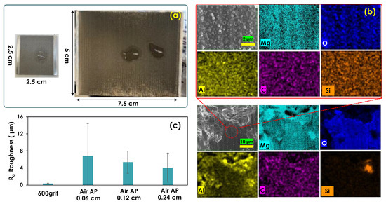
Figure 7.
(a) Air AP-treated AZ91D plates in two different sizes. The surfaces were treated with five swings of air AP. Water droplets on the surfaces indicate they are hydrophilic. (b) SEM-EDS images of the air AP-treated AZ91D with elemental maps in plan views. (c) Surface roughness analysis of the air AP-treated AZ91Ds with different interspacing distances and the reference 600 grit-finished surface.
The MIL23377 primer coatings on the air AP-treated surfaces exhibited excellent adhesion bonding. All the primer spray coatings on the air AP-treated and reference specimens were 40–43 μm thick. The ASTM D3359 crosshatch adhesion test was performed to evaluate the primer coating adhesion to the air AP-treated surfaces. The average primer thickness and the adhesion rating are indicated at the bottom of each photo in Figure 8. The crosshatch test showed that all the primer coatings, including those on the reference specimen, had the highest level of adhesion, ASTM class 5B, meaning that they showed no signs of damage in the as-coated condition.
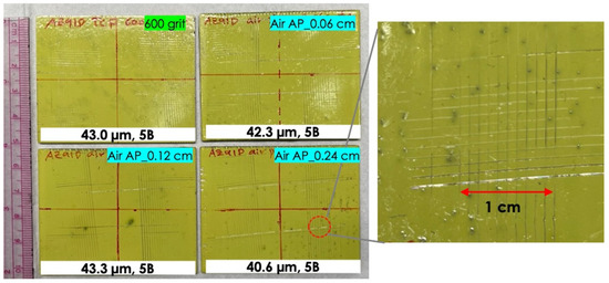
Figure 8.
Various MIL23377 primer-coated AZ91D samples (5 cm × 7.5 cm with ~43 μm coating thickness) after the ASTM D3359 coating adhesion test.
The coating adhesion was also evaluated by a corrosion exposure test in a salt spray chamber. All the tested panels had a coating thickness between 40 and 53 μm. Prior to the salt spray test, an X-cut test (ASTM D3359, method A) was conducted on the half area of each panel to evaluate the coating adhesion and corrosion through the X-cuts, as shown in Figure 9a. Fractional ratings of 5A, the highest level of adhesion (i.e., no peeling or removal) were confirmed for all the panels in the as-coated condition. Then, a long-term salt spray exposure test was conducted for all the primer-coated panels for 190 h. The primer coating of the air AP-treated surface had a significantly smaller corrosion area than the control panel, as identified by a contrast-based image analysis to distinguish the corroded area (darker tone) from the undamaged coating area (lighter tone).
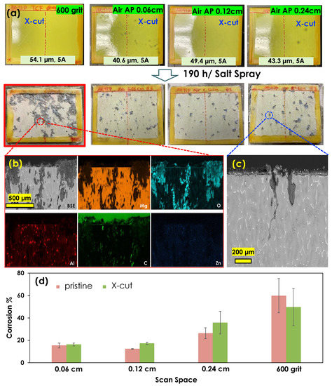
Figure 9.
(a) MIL23377 primer-coated panels (5 cm × 7.5 cm) with coating thicknesses before and after the X-cut test and primer-coated sample images after 190 h in a salt spray chamber (The photo images were taken after the samples were rinsed with water); (b) corresponding cross-sectional SEM-EDS images and elemental mappings from the reference specimen (600 grit surface-finished AZ91D) after the salt spray; (c) corresponding cross-sectional SEM image from the air AP-treated surface (0.24 cm interspacing distance); and (d) image analysis of corrosion areas of the specimens.
Additionally, the cross-sectional SEM-EDS images in Figure 9b show that the corrosion penetrated to a depth of >800 μm into the AZ91D substrate that was finished with 600 grit for the MIL primer coating, whereas Figure 9c shows that the corrosion penetrated to a depth of ~300 μm within a limited area in the air AP specimen with 0.24 cm spacing. An image analysis was conducted to further quantify the corrosion area of each specimen, and the results are shown in Figure 9d. The analysis indicates that the corrosion area of the air AP specimen treated with 0.06 cm spacing was 15.4% of the entire area—four times smaller than that of the control specimen, which was 59.9% of the entire area. Moreover, because of the strong adhesion bonding between the primer coating and the treated surface, the corrosion effect through the X-cut halves of the panels was negligible compared with the corrosion effect on the intact coated surface.
Further microscopic analysis was performed to understand how the interface structures of the primer layer and the Mg substrate mitigated corrosion. The cross-sectional SEM-EDS images shown in Figure 10 indicate that the air AP-treated surfaces were very rough with deep craters and particle agglomeration, in contrast to the smooth surface of the 600 grit-finished specimen. An O- and C-rich surface layer formed on the air AP-treated surface, whereas only a thin O-rich layer formed on the reference specimen surface. The smooth, thin MgO layer of the reference specimen showed weak adhesion for the primer layer, resulting in voids at the interface (see Figure 10a), whereas the rough O- and C-rich Mg layer (possibly MgCO3) of the air AP-treated surface interlocked strongly with the primer layer, presumably preventing defective voids from forming (see Figure 10b).
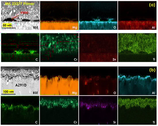
Figure 10.
Cross-sectional SEM-EDS images with corresponding elemental maps for the MIL23377 primer-coated AZ91D surfaces after the salt spray test: (a) 600 grit-finished AZ91D and (b) air AP-treated AZ91D.
3.4. Nitrogen Atmospheric Plasma Treatment
The N2 AP treatment was evaluated for its effectiveness in improving primer coating adhesion and scalability. High-pressure die casting (HPDC) AZ91D was used for this study instead of normal die casting AZ91D, due to a sample shortage. Therefore, the evaluation of the N2 AP treatment and MIL23377 was conducted only on HDPC AZ91D substrates. A single swing with different operation parameters (e.g., speed, ionized gas flow rate, and generator settings) was performed on a 7.6 cm × 10.2 cm × 0.3 cm AZ91D panel (see Table S2 and Figure S3 in Supplementary Information). The single-swing N2 AP treatment created up to 1.8 μm of microscale surface roughness. Then, the MIL23377 primer coating was applied, and X-cut and long-term salt spray tests were conducted for 481 h. The findings indicated that N2 AP on HPDC AZ91D had a similar potential to that of the CO2 and air AP treatments on normal casting AZ91D in terms of enhancing primer coating adhesion and mitigating significant corrosion (see Figure S4 in Supplementary Information). Furthermore, under certain conditions, the N2 AP treatment showed the potential to form a corrosion-resistant layer on HPDC AZ91D. Future work will be conducted to further explore this approach.
3.5. Cost Analysis
A preliminary OPEX analysis of atmospheric gas plasma treatment was performed to examine the benefits and potential challenges in cleaning and pretreating coatings on Mg alloy structures. From Equations (1)–(3) and Table 1, we obtained OPEXs for CO2, N2, and air AP treatments as 30.62 USD/m2, 35.45 USD/m2, and 29.74 USD/m2, respectively. The major cost contributor is the price of feeding gas sources (i.e., CO2, N2, and air), each of which accounts for 98% of its respective OPEX. However, the cost of air can be eliminated by replacing the high-pressure steel cylinder with a filtered air compressor, thereby reducing the OPEX of the air AP treatment to 0.66 USD/m2, which is the electricity cost. Price sensitivities were also calculated by changing the area scan rate and gas prices because a faster area scan rate decreases the total cost. Price sensitivities are shown in Figure 11 as error bars, in which the minimum OPEXs correspond to a 20% increase in the area scan rate and a 20% decrease in the gas prices, and the maximum OPEXs correspond to a 20% decrease in the area scan rate and a 20% increase in the gas prices.
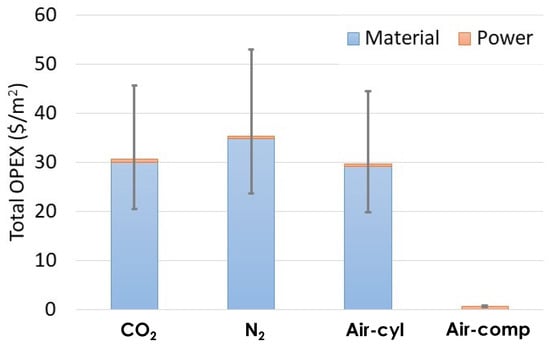
Figure 11.
Total OPEXs per unit area of AP treatments using CO2, N2, and air from a high-pressure steel cylinder (cyl) and a filtered air compressor (comp).
The conventional car body coating process consists of five steps: pretreatment, electrodeposition, rust-proofing, primer application, and topcoat application [21]. To compare our preliminary AP cost with other values, we first need to identify the corresponding steps of our AP treatment. As our AP treatment is applied to raw metals, it is expected to serve as an alternative to the first two steps: pretreatment and electrodeposition. We attempted to find published costs for pretreatment/electrodeposition, but only one website indicated that pretreatment chemical costs range from 0.057 USD/m2 to 0.074 USD/m2 [40]. The chemical material costs alone are significantly lower than the AP material cost. However, considering that the chemical coating process is more complicated and requires the operation of large equipment such as chemical baths, the actual OPEX for the chemical coating process would likely be higher. We also investigated the cost of a commercial car coating service, which would correspond to the final two steps: primer and topcoat application. While it is difficult to directly compare our AP cost with commercial car coating services, we can at least gain some perspective. Car painting costs vary significantly, but a typical range is USD 2500 to USD 3500 per car [41], and a car’s surface area is approximately 5.57 m2 (60 square feet) [42]. Consequently, the car coating cost per unit area ranges from 448.8 USD/m2 to 628.3 USD/m2.
4. Conclusions
Atmospheric pressure plasma surface treatments on AZ91D Mg alloy improved primer coating adhesion and corrosion resistance. Three commercial primers (i.e., ZnP, epoxy, and MIL23377) were applied on CO2, air, and N2 AP-treated surfaces to study the increased corrosion resistance associated with improved coating adhesion to the nano-/microrough surface. The AP treatments of CO2, air, and N2, which resulted in a significant increase in surface roughness (Ra), ranged from 1.3 to 1.5 μm, 1.4 to 12.2 μm, and 0.3 to 1.8 μm, respectively, compared with the reference surface finished with 600 grit, which ranged from 0.17 to 0.25 μm. All three primers exhibited enhanced adhesion on the AP-treated surfaces. Microscopic analysis showed interlocking of the primer and nano-/microrough surface at the interface of the AP-treated surface, which caused higher adhesion of the commercial primer coatings to the surface and thus significantly improved corrosion resistance. In particular, the crosscut tests of the MIL23377 primer on the air AP-treated surfaces showed the highest level of adhesion, ASTM class 5B. Moreover, the corrosion area of the MIL23377 coating on the air AP specimen was up to four times smaller than that of the 600 grit-finished reference specimen. The estimated preliminary operation expenses for AP treatment using CO2, N2, and air were estimated at USD 30.62, USD 35.45, and USD 29.75 per m2, respectively. However, if an air compressor was used, the cost for air AP treatment would be as low as USD 0.66 per m2. The evaluation of the scalability, performance, and operating cost of each treatment indicated that air AP treatment has the potential to enhance the coating adhesion and corrosion resistance of Mg alloys in a more cost-efficient manner than CO2 and N2 AP treatments.
Supplementary Materials
The following supplementary information can be downloaded at: https://www.mdpi.com/article/10.3390/coatings13050897/s1, Figure S1: Atmospheric-pressure N2 plasma treatment on AZ91D; Table S1: Water contact angle measurement on CO2 and Air AP-treated AZ91D surfaces; Figure S2. Corrosion resistance data of CO2 AP-treated AZ91D and untreated surfaces; Table S2. Process parameters of N2 AP treatment; Figure S3. Optical microscopic images of AZ91D treated with one time swing of N2 AP treatment; Figure S4. Scalable MIL 23377 primer-coated AZ91D sheet samples (7.6 × 10.2 × 0.2 cm) after 481 h in a salt spray chamber
Author Contributions
G.G.J.; Conceptualization, supervision, methodology, investigation, writing—original draft, and data curation, J.J.; Methodology, investigation, data curation, writing-review and editing, S.Y.; writing-original draft preparation, writing-review and editing, methodology, investigation, visualization, data curation, M.Y.; Methodology, Y.F.S.; Data curation, J.W.; Data curation, M.S.S.; Data curation, J.K.K.; Data curation. All authors have read and agreed to the published version of the manuscript.
Funding
This work was supported by the US Department of Energy (DOE) Office of Energy Efficiency and the Renewable Energy Vehicle Technologies Office’s Light Metals Core Program and the DOE Office of Technology Transitions’ Technology Commercialization Fund. The research was conducted at ORNL, which is managed by UT-Battelle LLC for DOE under contract DE-AC05-00OR22725.
Institutional Review Board Statement
Not applicable.
Informed Consent Statement
Not applicable.
Data Availability Statement
Available upon request from the corresponding author.
Acknowledgments
SEM and XRD were performed at the Center for Nanophase Materials Sciences, which is located at ORNL and sponsored by DOE’s Scientific User Facilities Division. Harry III Meyer collected XPS data. Peter Yancey (Atmospheric Plasma Solutions, 11301 Penny Road, Cary, NC 27518, USA) supported the production of atmospheric plasma-treated Mg alloy samples. This research used resources of the National Energy Research Scientific Computing Center; a DOE Office of Science User Facility supported by the Office of Science of the U.S. Department of Energy under Contract No. DE-AC02-05CH11231 using NERSC award BES-ERCAP0024568.
Conflicts of Interest
The authors declare no conflict of interest.
References
- Czerwinski, F. Current Trends in Automotive Lightweighting Strategies and Materials. Materials 2021, 14, 6631. [Google Scholar] [CrossRef] [PubMed]
- Kumar, D.; Phanden, R.K.; Thakur, L. A review on environment friendly and lightweight Magnesium-Based metal matrix composites and alloys. Mater Today-Proc. 2021, 38, 359–364. [Google Scholar] [CrossRef]
- Joost, W.J.; Krajewski, P.E. Towards magnesium alloys for high-volume automotive applications. Scr. Mater. 2017, 128, 107–112. [Google Scholar] [CrossRef]
- Brady, M.P.; Joost, W.J.; Warren, C.D. Insights from a Recent Meeting: Current Status and Future Directions in Magnesium Corrosion Research. Corrosion 2017, 73, 452–462. [Google Scholar] [CrossRef]
- Bender, S.; Goellner, J.; Heyn, A.; Boese, E. Corrosion and corrosion testing of magnesium alloys. Mater. Corros. 2007, 58, 977–982. [Google Scholar] [CrossRef]
- Liu, M.; Guo, Y.; Wang, J.; Yergin, M. Corrosion avoidance in lightweight materials for automotive applications. NPJ Mater. Degrad. 2018, 2, 24. [Google Scholar] [CrossRef]
- Xu, W.Q.; Birbilis, N.; Sha, G.; Wang, Y.; Daniels, J.E.; Xiao, Y.; Ferry, M. A high-specific-strength and corrosion-resistant magnesium alloy. Nat. Mater. 2015, 14, 1229–1235. [Google Scholar] [CrossRef]
- Vaghefinazari, B.; Wierzbicka, E.; Visser, P.; Posner, R.; Arrabal, R.; Matykina, E.; Mohedano, M.; Blawert, C.; Zheludkevich, M.; Lamaka, S. Chromate-Free Corrosion Protection Strategies for Magnesium Alloys-A Review: PART I-Pre-Treatment and Conversion Coating. Materials 2022, 15, 8676. [Google Scholar] [CrossRef] [PubMed]
- Dzikova, J.; Fintova, S.; Kajanek, D.; Florkova, Z.; Wasserbauer, J.; Dolezal, P. Characterization and Corrosion Properties of Fluoride Conversion Coating Prepared on AZ31 Magnesium Alloy. Coatings 2021, 11, 675. [Google Scholar] [CrossRef]
- Cipriano, A.F.; Lin, J.J.; Miller, C.; Lin, A.; Alcaraz, M.C.C.; Soria, P.; Liu, H.N. Anodization of magnesium for biomedical applications—Processing, characterization, degradation and cytocompatibility. Acta Biomater. 2017, 62, 397–417. [Google Scholar] [CrossRef]
- Simchen, F.; Sieber, M.; Mehner, T.; Lampke, T. Characterisation Method of the Passivation Mechanisms during the pre-discharge Stage of Plasma Electrolytic Oxidation Indicating the Mode of Action of Fluorides in PEO of Magnesium. Coatings 2020, 10, 965. [Google Scholar] [CrossRef]
- Zhang, Z.P.; Yu, G.; Ouyang, Y.J.; He, X.M.; Hu, B.N.; Zhang, J.; Wu, Z.J. Studies on influence of zinc immersion and fluoride on nickel electroplating on magnesium alloy AZ91D. Appl. Surf. Sci. 2009, 255, 7773–7779. [Google Scholar] [CrossRef]
- Lu, F.F.; Ma, K.; Li, C.X.; Yasir, M.; Luo, X.T.; Li, C.J. Enhanced corrosion resistance of cold-sprayed and shot-peened aluminum coatings on LA43M magnesium alloy. Surf. Coat. Tech. 2020, 394, 125865. [Google Scholar] [CrossRef]
- Yao, H.L.; Hu, X.Z.; Wang, H.T.; Chen, Q.Y.; Bai, X.B.; Zhang, M.X.; Ji, G.C. Microstructure and Corrosion Behavior of Thermal-Sprayed Hydroxyapatite/Magnesium Composite Coating on the Surface of AZ91D Magnesium Alloy. J. Therm. Spray Technol. 2019, 28, 495–503. [Google Scholar] [CrossRef]
- Polizos, G.; Jang, G.G.; Smith, D.B.; List, F.A.; Lassiter, M.G.; Park, J.; Datskos, P.G. Transparent superhydrophobic surfaces using a spray coating process. Sol. Energy Mater. Sol. Cells 2018, 176, 405–410. [Google Scholar] [CrossRef]
- Jang, G.G.; Smith, D.B.; Polizos, G.; Collins, L.; Keum, J.K.; Lee, D.F. Transparent superhydrophilic and superhydrophobic nanoparticle textured coatings: Comparative study of anti-soiling performance. Nanoscale Adv. 2019, 1, 1249–1260. [Google Scholar] [CrossRef]
- Jang, G.G.; Smith, D.B.; List, F.A.; Lee, D.F.; Ievlev, A.V.; Collins, L.; Park, J.; Polizos, G. The anti-soiling performance of highly reflective superhydrophobic nanoparticle-textured mirrors. Nanoscale 2018, 10, 14600–14612. [Google Scholar] [CrossRef]
- Saji, V.S. Recent progress in superhydrophobic and superamphiphobic coatings for magnesium and its alloys. J. Magnes. Alloy. 2021, 9, 748–778. [Google Scholar] [CrossRef]
- Lu, X.Y.; Zuo, Y.; Zhao, X.H.; Tang, Y.M.; Feng, X.G. The study of a Mg-rich epoxy primer for protection of AZ91D magnesium alloy. Corros. Sci. 2011, 53, 153–160. [Google Scholar] [CrossRef]
- Lu, X.Y.; Sun, S.C.; Fan, Q.Q.; Pei, X.J.; Dun, Y.C.; Feng, X.G.; Zou, C.; Lu, W. Investigation of Protective Performance of a Mg-Rich Primer Containing Aluminum Tri-Polyphosphate on AZ91D Magnesium Alloy in Simulated Acid Rain. Coatings 2019, 9, 649. [Google Scholar] [CrossRef]
- Akafuah, N.K.; Poozesh, S.; Salaimeh, A.; Patrick, G.; Lawler, K.; Saito, K. Evolution of the Automotive Body Coating Process-A Review. Coatings 2016, 6, 24. [Google Scholar] [CrossRef]
- Boerio, F.J.; Roby, B.; Dillingham, R.G.; Bossi, R.H.; Crane, R.L. Effect of grit-blasting on the surface energy of graphite/epoxy composites. J. Adhes. 2006, 82, 19–37. [Google Scholar] [CrossRef]
- Maroofi, A.; Safa, N.N.; Ghomi, H. Atmospheric air plasma jet for improvement of paint adhesion to aluminium surface in industrial applications. Int. J. Adhes. Adhes. 2020, 98, 102554. [Google Scholar] [CrossRef]
- Yim, J.H.; Rodriguez-Santiago, V.; Williams, A.A.; Gougousi, T.; Pappas, D.D.; Hirvonen, J.K. Atmospheric pressure plasma enhanced chemical vapor deposition of hydrophobic coatings using fluorine-based liquid precursors. Surf. Coat. Tech. 2013, 234, 21–32. [Google Scholar] [CrossRef]
- Jha, S.; Bhowmik, S.; Bhatnagar, N.; Bhattacharya, N.K.; Deka, U.; Iqbal, H.M.S.; Benedictus, R. Experimental Investigation into the Effect of Adhesion Properties of PEEK Modified by Atmospheric Pressure Plasma and Low Pressure Plasma. J. Appl. Polym. Sci 2010, 118, 173–179. [Google Scholar] [CrossRef]
- Dupuis, A.; Ho, T.H.; Fahs, A.; Lafabrier, A.; Louarn, G.; Bacharouche, J.; Airoudj, A.; Aragon, E.; Chailan, J.F. Improving adhesion of powder coating on PEEK composite: Influence of atmospheric plasma parameters. Appl. Surf. Sci. 2015, 357, 1196–1204. [Google Scholar] [CrossRef]
- Wu, C.C.; Demaree, J.D.; Weerasooriya, A.; Bujanda, A.; Robinette, E.J. Enhanced Interfacial Adhesion of Nylon 66 to Epoxy Resin EPON 825 by Non-thermal Atmospheric Pressure Dielectric Barrier Discharge Plasmas. Coatings 2022, 12, 919. [Google Scholar] [CrossRef]
- Munoz, J.; Bravo, J.A.; Calzada, M.D. Aluminum metal surface cleaning and activation by atmospheric-pressure remote plasma. Appl. Surf. Sci. 2017, 407, 72–81. [Google Scholar] [CrossRef]
- Rodriguez-Villanueva, C.; Encinas, N.; Abenojar, J.; Martinez, M.A. Assessment of atmospheric plasma treatment cleaning effect on steel surfaces. Surf. Coat. Tech. 2013, 236, 450–456. [Google Scholar] [CrossRef]
- Favaro, M.; Patelli, A.; Ceccato, R.; Dire, S.; Callone, E.; Fredi, G.; Quaranta, A. Thin Films of Plasma-Polymerized n-Hexane and ZnO Nanoparticles Co-Deposited via Atmospheric Pressure Plasma Jet. Coatings 2021, 11, 167. [Google Scholar] [CrossRef]
- Jang, G.G.; Yeom, S.; Keum, J.K.; Yoon, M.; Meyer, H.I.; Su, Y.F.; Jun, J. Formation of carbon and oxygen rich surface layer on high purity magnesium by atmospheric carbon dioxide plasma. J. Magnes. Alloy. 2023, 11, 88–99. [Google Scholar] [CrossRef]
- Pappas, D.; Guist, S.; Ben Salem, D. Plasma Surface Engineering: An Enabling Technology Designed to Clean and Protect Printed Circuit Boards. In International Symposium on Microelectronics; International Microelectronics Assembly and Packaging Society: Pittsburgh, PA, USA, 2020; Volume 2020, pp. 000197–000200. [Google Scholar]
- ASTM B117-16; Standard Practice for Operating Salt Spray (Fog) Apparatus. ASTM International: West Conshohocken, PA, USA, 2016.
- KUB. Business Electric Rates as of May 2022. Available online: https://www.kub.org/bills-payments/understand-your-bill/business-rates/business-electric-rate-schedules/ (accessed on 14 June 2022).
- Industrial Grade Carbon Dioxide, 50 Pound High Pressure Steel Cylinder, CGA-320. Available online: https://www.airgas.com/product/Gases/Carbon-Dioxide/p/CD%2050S (accessed on 5 April 2022).
- Industrial Grade Nitrogen, Size 300 High Pressure Steel Cylinder, CGA-580. Available online: https://www.airgas.com/product/Gases/Nitrogen/p/NI%20300 (accessed on 26 September 2022).
- Breathing Grade Air, Size 300 High Pressure Steel Cylinder, CGA-346. Available online: https://www.airgas.com/p/AI%20B300 (accessed on 2 February 2023).
- MSG® Centac® C400 Centrifugal Air Compressor. Available online: https://www.ingersollrand.com/en-us/air-compressor/centrifugal-air-compressors/45-70-m3min-1600-2350-cfm (accessed on 14 February 2023).
- Hu, Y.C.; Guo, Y.F.; Sun, J.; Li, H.L.; Liu, W.Q. Progress in MgO sorbents for cyclic CO2 capture: A comprehensive review. J. Mater. Chem. A 2019, 7, 20103–20120. [Google Scholar] [CrossRef]
- Association, E. Applied Costs of Electrocoating. 2016. Available online: https://electrocoat.wildapricot.org/resources/Pictures/ECA_CostsBrochure_EmailPages.pdf (accessed on 4 January 2023).
- Kurczewski, N. How Much Does It Cost to Paint a Car? Car and Driver. 14 May 2019. Available online: https://www.caranddriver.com/features/a27438340/cost-to-paint-car/ (accessed on 4 January 2023).
- Jackson, L. Why there won’t be a solar powered car. The Washington Times, 26 July 2008. Available online: https://www.washingtontimes.com/blog/spinning-wheels-community-car-lovers/2008/jul/26/why-there-wont-be-a-solar-powered-car/ (accessed on 4 January 2023).


Disclaimer/Publisher’s Note: The statements, opinions and data contained in all publications are solely those of the individual author(s) and contributor(s) and not of MDPI and/or the editor(s). MDPI and/or the editor(s) disclaim responsibility for any injury to people or property resulting from any ideas, methods, instructions or products referred to in the content. |
© 2023 by the authors. Licensee MDPI, Basel, Switzerland. This article is an open access article distributed under the terms and conditions of the Creative Commons Attribution (CC BY) license (https://creativecommons.org/licenses/by/4.0/).