Abstract
High Z (atomic number) metallic foams with a low density and high purity are urgent demands in high energy-density physical experiments. They suppress plasma expansion and convert the laser pulses to X-rays more uniformly and efficiently. Thus, we synthesized an ultralow-density and high-purity Au foam hohlraum with a hierarchical porous structure via a template-dealloying method in this paper. Silica (SiO2) beads were introduced as the sacrificial templates due to their high stability at an elevated temperature. The Au and Ag nanoparticles were successively deposited onto the SiO2 templates via an electroless deposition process to form an Ag@Au@SiO2 core-shell structure. Cylindrical Ag@Au@SiO2 hohlraum was achieved using a filter-casting technique with a patented mold. Afterward, an Au-Ag alloy was generated during 36 h of calcination at 400 °C. Self-supported Au foam hohlraum with the hierarchical porous structure was gained after the SiO2 templates were removed, followed by the dealloying of the Ag from the Au-Ag alloy. A self-supporting Au foam hohlraum with a density as low as 0.2 g/cm3 and a purity of 99.37% was achieved, and the density decreased by about 44.5% when compared with our previous Au foam (density: 0.36 g/cm3, purity: less than 96%) using microspherical polystyrene as the sacrificial template. Thus, the ultralow-density, high-purity Au foam hohlraum may exhibit profound application in high-energy physical experiments in the near future.
1. Introduction
Low-density, high-purity metallic foams with hierarchical porous structures have attracted tremendous interest in academic and industrial circles [1,2,3,4]. Firstly, the metallic mainframe provides the material with high electrical, excellent heat conductivity, and high strength [3]; additionally, the hierarchical porous structure with high porosity has an enhanced specific area to absorb more ions (or molecules) and facilitate mass transportation [5,6]. Thus, they are widely used in catalytic, electrochemical, sensor, and purification [7,8,9,10,11,12,13,14,15]. Synthesis of porous noble metal materials with multimodal structures is still challenging, although significant progress in fabricating multimodal porous ceramics, metal oxides, and organic carbon has been achieved.
The exploitation of nuclear fusion, which generates endless energy without any carbon dioxide or wastes from the reaction process, has been considered one of the promising solutions to the global energy crisis. At present, two possible methods are ongoing, one is the international thermonuclear experimental reactor (ITER) project and another way to obtain a controlled fusion reaction is inertial confinement fusion (ICF) with high-power lasers [16]. In the indirect-drive ICF, a high Z (high atomic number, high density, and high radiation opacity) metal hohlraum, which converts the laser pulses into X-rays, is indispensable [17]. The available X-ray radiation amount depends on the conversion efficiency of the laser to X-ray and the X-ray reemission efficiency of the hohlraum [18,19]. According to the theoretical and experimental calculations, the foam hohlraum with lower density and higher purity features lower X-ray energy loss with higher conversion efficiency and obtains a higher radiation temperature [19,20,21,22]. Thus, as the frequently utilized high Z metal, the Au foam having a desirable density, purity, and porosity, is a promising candidate for hohlraum wall materials in ICF facilities [23,24].
Template-assisted synthesis and dealloying are the two main methods used to form pores in metals [25]. Templating uses sacrificial organic or inorganic templates to construct pores, and these pore sizes are template-dependent, ranging from a few nanometers to tens of micrometers [26,27,28]. While in the dealloying process, the least noble component in an alloy is selectively removed by corrosion, leaving the more noble element forming a nanoporous structure [7,29,30]. The pore size distribution can only be adjusted in a narrow range by controlling the ratios of the components in the alloy. However, obtaining porous metals with an ultralow density by a single method is hard to achieve. Thus, combing the templating and dealloying techniques could fabricate multimodal porous noble metal materials [31].
Herein, a template-dealloying strategy to fabricate ultralow-density, high-purity gold foam hohlraum with a hierarchical porous structure was demonstrated, which consisted of multiple steps. The monodispersed silica (SiO2) beads preseeding with Au nanoparticles were selected as the sacrificial templates, followed by Au and Ag electroless deposition, and an Ag@Au@SiO2 core-shell structure was obtained. Subsequently, the Ag and Au were alloyed at a constant temperature for tens of hours, followed by removing the SiO2 templates and Ag component corrosion, and an Au foam hohlraum with a hierarchical porous structure was gained.
2. Experimental Section
2.1. Materials
The monodispersed SiO2 beads (10 μm), chloroauric acid (HAuCl4·4H2O), silver nitrate (AgNO3), tetraoctyl ammonium bromide, and hydroxylamine hydrochloride were obtained from Aladdin.
2.2. Synthesis of Au Foam Hohlraum
The preparation of low-density Au foam hohlraum is multistep works, as schematically shown in Figure 1. Step 1, the Au nanoparticle colloid, which served as the nucleation site for the subsequent electroless Au deposition, was prepared according to the literature [32]. The monodisperse SiO2 beads were modified by the 3-aminopropyltriethoxysilane, resulting in positively charged SiO2 beads grafted by the amino groups. Step 2, the Au nanoparticles firmly covered the SiO2 beads by dropwise adding the Au nanoparticle colloid into the SiO2 beads solution and sufficiently stirring. After washing and centrifugation, the Au nanoparticles coated SiO2 beads were re-dispersed in 80 mL of deionized water. Step 3, a thicker Au nanoparticles layer was obtained by an electroless deposition process, in which the polyvinypyrrolidone (PVP), hydroxylamine hydrochloride, and HAuCl4 were used as a stabilizing agent, reduction agent, and an Au source, respectively. Step 4, after careful washing and centrifugation, the sample was re-dispersed in 80 mL of deionized water for Ag electroless deposition. During the Ag deposition process, the PVP was introduced as a stabilizer, aqueous ammonia and glucose as reductants, and AgNO3 as an Ag source, respectively. Step 5, the Ag@Au@SiO2 beads were dispersed in 2 mL of ionized water after the as-received solution was washed and centrifuged. A free-standing hollow cylinder-shaped Ag@Au@SiO2 foam was formed by a filter-casting method using a patented mold (Figure 2). Step 6, after drying and demolding, the Ag@Au@SiO2 foam was calcined at 400 °C for 36 h in a flowing nitrogen atmosphere, forming an Au-Ag alloy on the outside surface of the SiO2 beads. Step 7, the SiO2 bead templates were removed in a hydrofluoric acid solution by gradually increasing the concentrations (1%, 4%, and 10%). Step 8, the less noble content of Ag in the Au-Ag alloy was selectively removed via a dealloying process, which was performed in a nitric acid solution by gradually increasing the concentration (3.55 M, 7.9 M, 11.9 M, and concentrated nitric acid). The Au foam hohlraum was washed several times with deionized water to remove the residual nitric acid and then placed in acetone to completely displace the water. Finally, an ultralow-density, high purity, and hierarchical porous Au foam hohlraum was obtained after drying in a supercritical CO2 atmosphere to prevent the Au foam hohlraum from shrinkage.
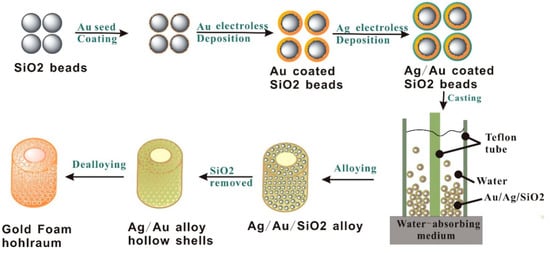
Figure 1.
Schematic illustration of Au foam hohlraum fabrication.
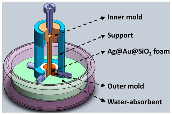
Figure 2.
The structure diagram of the patented mold used to fabricate Ag@Au@SiO2 hohlraum.
2.3. Characterization
The morphology of the as-received Au foams was investigated by a field-emission scanning electron microscope (FESEM), and the elemental compositions were investigated by energy dispersive spectrum (EDS), which is attached to the FESEM system. Meanwhile, a focus ion beam (FIB) was employed to slice the Au foam hohlraum and the thickness was observed by the FESEM. The densities of the Au foam hohlraum were obtained by dividing the mass of the Au foam hohlraum by the volume. The contents of impurities were analyzed by inductively coupled plasma mass spectrum (ICP-MS), and the carbon and oxygen contents were determined by a carbon analyzer. The ligament size distribution of the Au foams was calculated using an image analysis software (Image-Pro Plus) from the FESEM images. The N2 adsorption/desorption isotherms were conducted with a surface area analyzer at 196 °C. The specific surface and the pore distribution of the porous Au foams were estimated by the Brunauer-Emmett-Teller (BET) method and the density functional theory (DFT) program, respectively.
3. Results and Discussion
Firstly, the Au nanoparticle colloid used as the nucleation sites in the following Au electroless deposition process was synthesized using a spontaneous phase transfer method, which transfers the Au nanoparticles from the toluene to deionized water by the addition of 4-dimethylaminopridine [32]. The as-received Au nanoparticle colloid exhibits excellent stability and dispersion. Moreover, the Au nanoparticles in the colloid have a uniform size distribution with an average diameter of 5.7 nm, according to the SEM and TEM analysis (Figure 3), which is beneficial for the subsequent Au electroless deposition. The high-resolution TEM image in Figure 3c exhibits clear lattice fringes with an interplanar space of 0.235 nm, which can be well indexed to the Au (111) plane, confirming that the Au nanoparticles used in the phase transfer method are in a good crystalline structure.
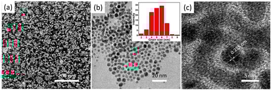
Figure 3.
(a) high magnification SEM image, (b) TEM image, and (c) high magnification TEM image of the prepared Au nanoparticles, the inset of (b) shows the size distribution of the prepared Au nanoparticles.
The Ag@Au@SiO2 core-shell microstructure was prepared by electroless deposition. During the Au electroless deposition, the pre-seeded Au nanoparticles on the SiO2 beads grew further, and the deposited Au nanoparticles layer thickened, as the hydroxylamine hydrochloride gradually reduced the HAuCl4 into Au nanoparticles. The deposited Au nanoparticles exhibit a uniform spherical morphology with a grain size of a few tens to a hundred nm (Figure 4) and without the observation of any aggregations. The PVP molecules, with the macromolecule long chains, stretch out and twine around the Au nanoparticles, preventing the Au nanoparticles aggregation with the help of constant stirring [31]. Moreover, the pre-seeded Au nanoparticles with lower energy provide multiple initial nucleation sites for the subsequent Au electroless deposition with a high reaction rate. While during the Ag electroless deposition process, aqueous ammonia and glucose were used as the reductants to reduce the AgNO3 into Ag nanoparticles which adhered to the deposited Au layer. The morphology of the synthesized Ag coating with different magnifications is shown in Figure 5, which differs from the Au nanoparticles via the electroless deposition process. The Ag nanoparticles gradually fill the gaps between the Au nanoparticles and form a compact layer. It may result that the gaps between the Au nanoparticles, with lower energy, are beneficial for Ag nucleation. Au electroless deposition must be carried out before Ag electroless deposition, because depositing Au on Ag may result in competing Ag0/Au3+ galvanic and electroless deposition reduction reactions [33].
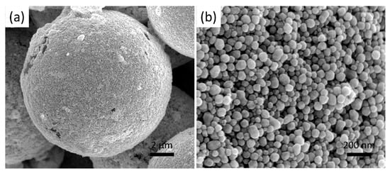
Figure 4.
(a) low and (b) high magnification SEM images of SiO2 beads after Au nanoparticles electroless deposition.
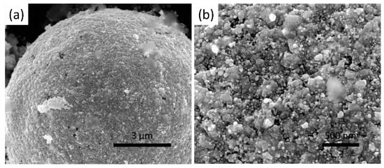
Figure 5.
(a) low and (b) high magnification SEM images of SiO2 beads after Ag nanoparticles electroless deposition.
As the electroless deposition of the Au and Ag was complete, the coated SiO2 beads were collected, re-dispersed in distilled water, and then cast to construct an Ag@Au@SiO2 hohlraum. Due to the Ag@Au@SiO2 beads, prepared via the multi-steps, having good dispersity, thus, they can be easily dispersed in distilled water. A self-designed mold (Figure 2) was employed to cast the Au foam hohlraum. The mold contains four parts, a platform, a hollow support, a Teflon inner mold, and a Teflon outer mold. The platform, filled with compacted plaster of Paris (CaSO4), is used to timely absorb water, solidify the Ag@Au@SiO2 foam, and support the whole mold during the casting process. The Teflon outer mold is fixed to the hollow support with four bolts, while the inner mold is placed in the guide hole of the hollow support. The Ag@Au@SiO2 water suspension is dropped into the gap between the outer and inner Teflon mold and settled down gradually with a random arrangement. Thus, it is easy to conclude that the outer diameter of the inner Teflon mold and the inner diameter of the outer Teflon mold determine the inner and outer diameter of the Au hohlraum, and the height of the molds limit the height of the hohlraum. Furthermore, multiple series of inner and outer molds are designed to meet the diverse demands of the ICF experiments. Eventually, all the Ag@Au@SiO2 beads settled down and a hohlraum, with the expected shape and size, formed. Demolding can be readily performed by disassembling the fixed bolds and pulling out the inner mold after desiccation at 40 °C in an incubator for half an hour. The fabricated hohlraum was calcinated in an N2 atmosphere at a fixed temperature of 400 °C for 36 h after demolding, and the alloying reaction of the Au and Ag took place during the heat treatment. Figure 6 shows the SEM images of the obtained Au-Ag alloy with different magnifications. The Au-Ag alloy is tightly adhered to the SiO2 beads and exhibits a porous nanostructure with varied alloy nanoparticle grain sizes, the morphology of which is different from the deposited Au nanoparticles and the coated Ag layer. The volume of the metal nanoparticles gradually shrinks to form a porous nanostructure when the alloying is processed at a relatively high temperature. Finally, an Au foam hohlraum, with the expected size and shape, was obtained by removing the sacrificial SiO2 template and selectively etching the less noble Ag component in the alloy.
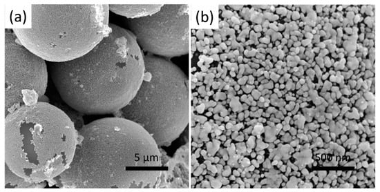
Figure 6.
(a) low and (b) high magnification SEM images of Au-Ag alloy coated on SiO2 beads after calcined at 400 °C for 36 h.
It is well known that the densities of the synthesized Au foam hohlraum can be facile adjusted by tuning the diameter of the SiO2 beads, varying the mole ratios of the deposited Au and Ag, as well as controlling the amount (thickness) of the coated Au and Ag during electroless deposition conditions. In our study, other sizes of SiO2 bead were also selected to fabricate Au hohlraum, all exhibiting low density and high purity using the template-dealloying method, and the larger the SiO2 bead, the lower density achieved. However, the thickness of the Au hohlraum is limited to 150~200 μm to meet the physical experiment design, and when the chosen SiO2 bead is more than 10 μm, the strength and mechanical performance of the Au hohlraum will decrease. Thus, we selected the 10 μm SiO2 bead as the template. In the present work, the Au foam hohlraum, with varied densities, was achieved by simply adjusting the mole ratios of the deposited Au and Ag layer with a fixed size of SiO2 beads and Au amount.
Figure 7 shows the SEM images of the synthesized Au foam hohlraum with different densities by the template-dealloying method, in which SiO2 beads (10 μm) as templates. As can be seen, the Au foam hohlraum with a hierarchical porous structure is composed of single self-supporting hollow Au shells stacked closely together. The pores mainly consist of three parts, the hollow shell structure after removing the SiO2 templates, the porous nanostructure after selectively etching the less noble Ag component in the Au-Ag alloy, and the gaps between the randomly stacked shells. The insets of Figure 7a,d,g show the relevant digital images of the prepared Au foam hohlraum, and significant color changes are observed with the decrease of the densities, varying from golden to bronze and further to brown. The yellow feature of bulky gold comes from the complementary blue absorption by the interband transition. In Au foams, the free electrons of nanostructures interact with light, leading to localized surface plasma. The plasma absorbs the light out of the blue range. Thus, the Au foams’ reflected spectrum and color change (Figure 8). In addition, when the Au density decreases, the nanostructures would be smaller and can trap more light in the entire spectrum, resulting in a darker foam. The Au foam hohlraum densities decrease as the thickness of the porous Au shell reduces. The thinner the Au shell, the lower density it has. Taking the Au foam hohlraum with a density of 0.41 g/cm3 as an example, the thickness is 170~270 nm. The thickness of the Au shell decreases to 150~200 nm as the density reduces to 0.30 g/cm3 and further becomes 76~140 nm as the density decreases to 0.20 g/cm3. Furthermore, the ligament size distribution of the porous Au shell is closely relevant to the densities of Au foam hohlraum. For example, when the Au foam hohlraum has a density of 0.41 g/cm3, as high as 76% of ligament distributes in a narrow range of 45~55 nm. As the density of Au foam hohlraum comes to 0.30 g/cm3, the distribution range of ligament size gradually widens, from 35 to 65 nm, and the 45~55 nm ligament takes up to 57%. As the density of Au foam hohlraum further decreases to 0.20 g/cm3, the ligament size distribution further broadens to the range of 45~100 nm, and only 11% of the ligament is between 45 and 55 nm, while about 72% of the ligament distributes from 65 to 85 nm. What’s more, it is observed from Figure 7i that the Au foam hohlraum with a density of 0.20 g/cm3 almost consists of a single thin layer of nanoporous structure and further decreases the thickness of the plated layer will result in the crack or collapse of the Au shell (Figure 9). Thus, it is believed that the Au layer thickness with a density of 0.20 g/cm3 is near the limit thickness, and the density is close to the limit density of Au foam hohlraum prepared by the template-dealloying method using the SiO2 beads (10 μm) as the sacrificial template.
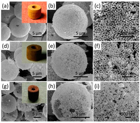
Figure 7.
SEM images of Au foam hohlraum with a density of (a–c) 0.41, (d–f) 0.30, and (g–i) 0.20 g/cm3 with different magnifications, the insets of (a,d,g) show the digital images of the corresponding Au foam hohlraum.
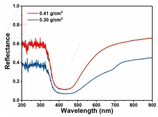
Figure 8.
Reflection spectra of Au foam hohlraum with different densities of 0.41 g/cm3 and 0.30 g/cm3.
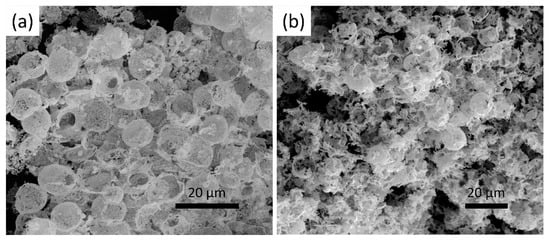
Figure 9.
SEM images of (a) the cracked and (b) collapse of the Au foam.
Apart from the hierarchical porous structure, another critical factor to ensure the Au foam hohlraum, with an ultralow density (as low as 0.20 g/cm3), is that the SiO2 beads are employed as templates, the size of which hardly shrink during the whole preparation process. Previous studies have shown that the polystyrene (PS) beads can be used as templates for the low-density Au foam synthesis and they can be easily removed by a heat treatment process when the Au and Ag are alloying [31,34,35]. Unfortunately, the size of the PS bead shrinks obviously (as high as 20%) during the pyrolysis process, which impedes the density of the Au foam from further decreasing. Moreover, the plated Au-Ag layer re-aggregates and regrows during heat treatment, showing a significant sintering morphology. However, it is far different from the situation with the PS beads as the template, where the SiO2 beads template will not remove during the alloying process, and no significant size shrinkage happens after the heat treatment. Additionally, only the re-aggregation and regrowth of the Au and Ag nanoparticles in the plated layer are detected during the alloying. Thus, when the PS and SiO2 beads are in the same diameter, and the ratio and amount of the gold and the silver are equal, a thinner Au shell can be achieved when using the SiO2 beads compared with the PS beads as a template.
The Au foam hohlraum, with a density of 0.20 g/cm3, was characterized by X-ray diffraction, and the result is presented in Figure 10a. Five diffraction peaks located at the 2θ of 38.3°, 44.6°, 64.6°, 77.5°, and 82.3° with different intensities are detected and can be well indexed to the (111), (200), (220), (311), and (222) planes of gold (PDF No. 00-001-1172), respectively. The pore properties are estimated by the N2 adsorption/desorption isotherm, and the results are shown in Figure 10b. Although the N2 adsorption/desorption isotherm of the Au foam hohlraum does not follow any particular pattern, due to some carbon contamination, it also exhibits an enhanced surface area of 57.14 m2/g from the multi-point BET test. It is much higher than the Au nanowires (6.9 m2/g) prepared by Ji et al., the Au foam (BET surface area: 10.9 m2/g) obtained from the combustion synthesis, and higher than the Au foam (BET surface area: 23.5 m2/g) fabricated using the PS beads as the template. It mainly results from the ultralow density of the Au foam hohlraum. Furthermore, the Au foam hohlraum also possesses a high pore volume of 0.11 cm3/g, which is close to the result using the PS beads as templates (0.10 and 0.15 cm3/g). The pore size distribution was calculated from the desorption branch using the DFT method. It shows that the Au foam hohlraum has an average pore diameter of about 38 nm with a wide range distribution from 25 to 360 nm, and the result is consistent with the ligament size distribution.
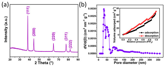
Figure 10.
(a) XRD pattern and (b) pore size distribution of the Au foam hohlraum, the inset of (b) shows the nitrogen adsorption/desorption isotherm of the Au foam hohlraum.
Achieving Au foam with a density as low as 0.28 g/cm3 was possible by a template-assisted method using the PS beads as a template [35]. However, the Au foam fabricated by this method contained a large amount of carbon impurity, with a minimum content of 4%. It may result from the incomplete pyrolysis of the PS template in the N2 atmosphere among the temperature ranging from 283 to 398 °C, only with a 96% theoretical weight loss of PS in this temperature region [28], as well as the alloying reaction of the Au and Ag, which takes place during this heat treatment. The existence of carbon as an impurity will decrease the conversion efficiency of the laser-X-ray due to the low atomic number [36]. The SiO2 microspheres were employed as templates to fabricate an Au foam to decrease the impurity and enhance the laser-X-ray conversion efficiency. High-purity Au foam was achieved via sintering the Ag-Au alloy, followed by the selected removal of the SiO2 template. The purity of the fabricated Au foam hohlraum was analyzed by the EDS, ICP-MS, and carbon analyzer, and the results are shown in Figure 11 and Table 1. According to the EDS spectrum, the vast majority of the detected element is gold, only a trace of carbon and oxygen components, and no Si or Ag are observed, indicating the complete removal of the Ag and SiO2 template. Carbon and oxygen are also confirmed by the carbon analyzer measurement, with a low concentration of 0.25 wt% and 0.38 wt%, respectively. The trace of C and O may result from the sample being exposed to the air atmosphere and adsorbing the CO2. Interestingly, less than 50 ppm of Si and Ag are detected by the ICP-MS method, although it holds a higher sensitivity and lower detecting limitation. On the one hand, the SiO2 templates have a high melting point and exhibit excellent stability when the heat treatment temperature is below the melting point. On the other hand, the flowing N2 during the calcination provides an inert atmosphere and guarantees no side-reaction occurring for the Ag component. Moreover, the SiO2 templates and the Ag component can be fully corroded by different acid solutions, resulting in a high-purity Au foam hohlraum.
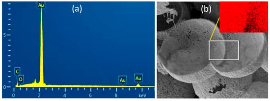
Figure 11.
(a) EDS spectrum and (b) cross image of the Au foam hohlraum, the inset of (b) shows the corresponding EDS elemental mapping image.

Table 1.
Elemental composition of pure Au foam hohlraum.
The fabricated Au foam hohlraum has been successfully applied to the physical experiment on the Shenguang Ⅲ laser facility, which is used to verify the foam’s gold suppression of plasma expansion and the enhancement of the re-emission energy flow in the hohlraum [37,38]. Compared to the Au block material with a density of 19.3 g/cm3, the velocities of the X-ray emission fronts moving off the wall are much smaller than the Au foam hohlraum with a density of 0.3 g/cm3 [39]. The XFC result indicates that the X-ray re-emissions from the Au foam hohlraum are enhanced by about 10.5%, between 1.1 and 1.5 ns, and the TGS measurement demonstrates that the time-integrated emission increases by about 12%. In addition, the increasing emission fraction by the Au foam increases with time [37,40]. Thus, it is believed that the ultralow-density, high-purity Au foam hohlraum with hierarchical porous structures synthesized by the template-dealloying method have advantages in symmetry controlling and lowering the plasma filling, which will have profound application in ICF high energy-density physical experiments.
4. Conclusions
In conclusion, we developed a new process to prepare ultralow-density, high-purity Au foam with a hierarchical porous structure using the template-dealloying method, using SiO2 beads as the sacrificial template. An Au foam hohlraum with low-density (0.20 g/cm3) and high-purity (99.37%) was obtained. This novel method not only separates the interaction between the sintering molding and template removal but also reduces the impurity content of the Au foam significantly. Moreover, it also decreases the radial shrinkage of the hollow microsphere, which benefits further lowering the density of the Au foam. By using the self-designed hohlraum forming mold, Au foam hohlraum, with different heights and different thicknesses of low-density layers, was obtained by adjusting the mode size. Moreover, the Au foam hohlraum samples fully retained the microstructure of the ultralow-density Au foam. The Au foam hohlraum consisted of an abundant free-standing single Au hollow shell composed of a homogeneous nanoporous structure.
Author Contributions
Conceptualization, Methodology, Investigation, Validation, and Writing—original draft, X.T. and J.W.; Writing—review and editing, J.L., C.W. and G.N.; Discussion, C.W.; Project administration, C.W.; Supervision, G.N. All authors have read and agreed to the published version of the manuscript.
Funding
This research was funded by the National Natural Science Foundation of China (Grant No. 11775204), the Presidential Foundation of China Academy of Engineering Physics (Grant No. YZJJLX2018011), and the Natural Science Foundation of Southwest University of Science and Technology (Grant No. 22ZX7104).
Institutional Review Board Statement
Not applicable.
Informed Consent Statement
Not applicable.
Data Availability Statement
Available upon request from the corresponding author.
Conflicts of Interest
The authors declare no conflict of interest.
References
- Wittstock, A.; Zielasek, V.; Biener, J.; Friend, C.M.; Baumer, M. Nanoporous gold catalysts for selective gas-phase oxidative coupling of methanol at low temperature. Science 2010, 327, 319–322. [Google Scholar] [CrossRef] [PubMed]
- Ding, Y.; Kim, Y.-J.; Erlebacher, J. Nanoporous gold leaf: “Ancient technology”. Adv. Mater. 2004, 16, 1897–1900. [Google Scholar] [CrossRef]
- Nyce, G.W.; Hayes, J.R.; Hamza, A.V.; Satcher, J.H., Jr. Synthesis and characterization of hierarchical porous gold materials. Chem. Mater. 2007, 19, 344–346. [Google Scholar] [CrossRef]
- Sun, F.; Yu, J.C. Photochemical preparation of two-dimensional gold spherical pore and hollow sphere arrays on a solution surface. Angew. Chem. Int. Ed. 2007, 46, 773–777. [Google Scholar] [CrossRef] [PubMed]
- Guo, B.; Ma, R.; Li, Z.; Guo, S.; Luo, J.; Yang, M.; Liu, Q.; Thomas, T.; Wang, J. Hierarchical N-doped porous carbons for Zn-Air batteries and supercapacitors. Nano-Micro Lett. 2020, 12, 20. [Google Scholar] [CrossRef]
- Wang, J.; He, Z.; Tan, X.; Wang, T.; Liu, L.; He, X.; Liu, X.D.; Zhang, L.; Du, K. High-performance 2.6 V aqueous symmetric supercapacitor based on porous boron doped diamond via regrowth of diamond nanoparticles. Carbon 2020, 160, 71–79. [Google Scholar] [CrossRef]
- Huang, J.; He, Z.; He, X.; Liu, Y.; Wang, T.; Chen, G.; Tang, C.; Jia, R.; Liu, L.; Zhang, L.; et al. Island-like nanoporous gold: Smaller island generates stronger surface-enhanced Raman scattering. ACS Appl. Mater. Interfaces 2017, 9, 28902–28910. [Google Scholar] [CrossRef]
- Tappan, B.C.; Steiner, S.A., III; Luther, E.P. Nanoporous metal foams. Angew. Chem. Int. Ed. 2010, 49, 4544–4565. [Google Scholar] [CrossRef]
- Liu, Z.; Searson, P.C. Single nanoporous gold nanowire sensors. J. Phys. Chem. B 2006, 110, 4318–4322. [Google Scholar] [CrossRef]
- Chandra, D.; Jena, B.K.; Raj, C.R.; Bhaumik, A. Functionalized mesoporous cross-linked polymer as efficient host for loading gold nanoparticles and its electrocatalytic behavior for reduction of H2O2. Chem. Mater. 2007, 19, 6290–6296. [Google Scholar] [CrossRef]
- Sondhi, P.; Stine, K.J. Methods to generate structurally hierarchical architectures in nanoporous coinage metals. Coatings 2021, 11, 1440. [Google Scholar] [CrossRef]
- Raj, D.; Scaglione, F.; Fiore, G.; Rizzi, P. Cost-effective nanoporous gold obtained by dealloying metastable precursor, Au33Fe67, reveals excellent methanol electro-oxidation performance. Coatings 2022, 12, 831. [Google Scholar] [CrossRef]
- Yadav, R.; Amoli, V.; Singh, J.; Tripathi, M.K.; Bhanja, P.; Bhaumik, A.; Sinha, A.K. Plasmonic gold deposited on mesoporous TixSi1-xO2 with isolated silica in lattice: An excellent photocatalyst for photocatalytic conversion of CO2 into methanol under visible light irradiation. J. CO2 Util. 2018, 27, 11–21. [Google Scholar] [CrossRef]
- Sasidharan, M.; Anandhakumar, S.; Bhanja, P.; Bhaumik, A. Highly efficient Au hollow nanosphere catalyzed chemo-selective oxidation of alcohols. J. Mol. Catal. A Chem. 2016, 411, 87–94. [Google Scholar] [CrossRef]
- Shangguan, Q.; Chen, Z.; Yang, H.; Cheng, S.; Yang, W.; Yi, Z.; Wu, X.; Wang, S.; Yi, Y.; Wu, P. Design of ultra-narrow band Graphene refractive index sensor. Sensors 2022, 22, 6483. [Google Scholar] [CrossRef] [PubMed]
- Craxton, R.S.; Aanderson, K.S.; Boehly, T.R.; Goncharov, V.N.; Harding, D.R.; Knauer, J.P.; McCrory, R.L.; McKenty, P.W.; Meyerhofer, D.D.; Myatt, J.F.; et al. Direct-drive inertial confinement fusion: A review. Phys. Plasmas 2015, 22, 110501. [Google Scholar] [CrossRef]
- Doppner, T.; Callahan, D.A.; Hurricane, O.A.; Hinkel, D.E.; Ma, T.; Park, H.-S.; Hopkins, L.F.B.; Casey, D.T.; Celliers, P.; Dewald, E.L.; et al. Demonstration of high performance in layered Deuterium-Tritium capsule implosions in uranium hohlraums at the National Ignition Facility. Phys. Rev. Lett. 2015, 115, 055001. [Google Scholar] [CrossRef]
- Chakera, J.A.; Arora, V.; Sailaja, S.; Kumbhare, S.R.; Naik, P.A.; Gupta, P.D.; Godwal, B.K. Dependence of soft X-ray conversion on atomic composition in laser produced plasma of gold–copper mix-Z targets. Appl. Phys. Lett. 2003, 83, 27–29. [Google Scholar] [CrossRef]
- Rosen, M.D.; Hammer, J.H. Analytic expressions for optimal inertial-confinement-fusion hohlraum wall density and wall loss. Phys. Rev. E 2005, 72, 056403. [Google Scholar] [CrossRef]
- Young, P.E.; Rosen, M.D.; Hammer, J.H.; Hsing, W.S.; Glendinning, S.G.; Turner, R.E.; Kirkwood, R.; Schein, J.; Sorce, C.; Satcher, J.H.; et al. Demonstration of the density dependence of X-ray flux in a laser-driven hohlraum. Phys. Rev. Lett. 2008, 101, 035001. [Google Scholar] [CrossRef]
- Schein, J.; Jones, O.; Rosen, M.; Dewald, E.; Glenzer, S.; Gunther, J.; Hammel, B.; Landen, O.; Suter, L.; Wallace, R. Demonstration of enhanced radiation drive in hohlraums made from a mixture of high-Z wall materials. Phys. Rev. Lett. 2007, 98, 175003. [Google Scholar] [CrossRef]
- Ye, Z.; Wu, P.; Wang, H.; Jiang, S.; Huang, M.; Lei, D.; Wu, F. Multimode tunable terahertz absorber based on a quarter graphene disk structure. Results Phys. 2023, 48, 106420. [Google Scholar] [CrossRef]
- Wilkens, H.L.; Nikroo, A.; Wall, D.R.; Wall, J.R. Developing depleted uranium and gold cocktail hohlraums for the National Ignition Facility. Phys. Plasmas 2007, 14, 056310. [Google Scholar] [CrossRef]
- Li, W.; Ma, J.; Zhang, H.; Cheng, S.; Yang, W.; Yi, Z.; Yang, H.; Zhang, J.; Wu, X.; Wu, P. Tunable broadband absorber based on a layered resonant structure with a Dirac semimetal. Phys. Chem. Chem. Phys. 2023, 25, 8489–8496. [Google Scholar] [CrossRef]
- Ron, R.; Haleva, E.; Salomon, A. Nanoporous metallic networks: Fabrication, optical properties, and applications. Adv. Mater. 2018, 30, 1706755. [Google Scholar] [CrossRef] [PubMed]
- Biener, J.; Nyce, G.W.; Hodge, A.M.; Biener, M.M.; Hamza, A.V.; Maier, S.A. Nanoporous plasmonic metamaterials. Adv. Mater. 2008, 20, 1211–1217. [Google Scholar] [CrossRef]
- Zhang, J.; Li, C.M. Nanoporous metals: Fabrication strategies and advanced electrochemical applications in catalysis, sensing and energy systems. Chem. Soc. Rev. 2012, 41, 7016–7031. [Google Scholar] [CrossRef]
- Zhang, K.; Tan, X.; Wu, W.; Tang, Y. Template synthesis of low-density gold foams: Density, microstructure and compressive strength. Mater. Res. Bull. 2013, 48, 3499–3504. [Google Scholar] [CrossRef]
- Erlebacher, J.; Aziz, M.J.; Karma, A.; Dimitrov, N.; Sieradzki, K. Evolution of nanoporosity in dealloying. Nature 2001, 410, 450–453. [Google Scholar] [CrossRef]
- McCue, I.; Benn, E.; Gaskey, B.; Erlebacher, J. Dealloying and dealloyed materials. Annu. Rev. Mater. Res. 2016, 46, 263–286. [Google Scholar] [CrossRef]
- Zhang, K.; Tan, X.; Zhang, J.; Wu, W.; Tang, Y. Template-dealloying synthesis of ultralow density Au foams with bimodal porous structure. RSC Adv. 2014, 4, 7196–7201. [Google Scholar] [CrossRef]
- Gittins, D.I.; Caruso, F. Spontaneous phase transfer of nanoparticulate metals from organic to aqueous media. Angew. Chem. Int. Ed. 2010, 40, 3001–3004. [Google Scholar] [CrossRef]
- Coaty, C.; Zhou, H.; Liu, H.; Liu, P. A scalable synthesis pathway to nanoporous metal structures. ACS Nano 2018, 12, 432–440. [Google Scholar] [CrossRef] [PubMed]
- Tan, X.; Niu, G.; Li, K.; Luo, J.; Wu, W.; Tang, Y. Preparation of monolithic foamed gold by a template deposit-dealloying method. Rare Met. Mater. Eng. 2013, 42, 162–165. [Google Scholar]
- Tan, X.; Niu, G.; Li, K.; Luo, J.; Han, S.; Ma, Y.; Li, J.; Tang, Y. Preparation of monolithic foamed Au/Ag alloy with hollow microspheres. High Power Laser Part. Beams 2012, 24, 353–356. [Google Scholar]
- Dong, Y.; Shang, W.; Yang, J.; Zhang, L.; Zhang, W.; Li, Z.; Guo, L.; Zhan, X.; Du, H.; Deng, B.; et al. The impact of low-Z impurities on X-ray conversion efficiency from laser-produced plasmas of low-density gold foam targets. Phys. Plasmas 2013, 20, 123305. [Google Scholar] [CrossRef]
- Zhang, L.; Ding, Y.; Lin, Z.; Li, H.; Jing, L.; Yuan, Z.; Yang, Z.; Tan, X.; Kuang, L.; Zhang, W.; et al. Demonstration of enhancement of X-ray flux with foam gold compared to solid gold. Nucl. Fusion 2016, 56, 036006. [Google Scholar] [CrossRef]
- Shang, W.; Zhang, W.; Dong, Y.; Huang, C.; Zhu, T.; Song, T.; Yang, J. Experimental study of X-ray emission properties of laser produced plasmas with Au and Au foam layer targets. J. Alloys Compd. 2013, 578, 1–4. [Google Scholar] [CrossRef]
- Zhang, L.; Ding, Y.; Jiang, S.; Yang, J.; Li, H.; Kuang, L.; Lin, Z.; Jing, L.; Li, L.; Deng, B.; et al. Reducing wall plasma expansion with gold foam irradiated by laser. Phys. Plasmas 2015, 22, 110703. [Google Scholar] [CrossRef]
- Zhang, L.; Dong, Y.; Jing, L.; Lin, Z.; Tan, X.; Kuang, L.; Li, H.; Shang, W.; Zhang, W.; Li, Z.; et al. Experimental study on improving hohlraum wall reemission ratio by low density gold foam. Acta Phys. Sin.-CH ED 2016, 65, 015202. [Google Scholar] [CrossRef]
Disclaimer/Publisher’s Note: The statements, opinions and data contained in all publications are solely those of the individual author(s) and contributor(s) and not of MDPI and/or the editor(s). MDPI and/or the editor(s) disclaim responsibility for any injury to people or property resulting from any ideas, methods, instructions or products referred to in the content. |
© 2023 by the authors. Licensee MDPI, Basel, Switzerland. This article is an open access article distributed under the terms and conditions of the Creative Commons Attribution (CC BY) license (https://creativecommons.org/licenses/by/4.0/).