Article

Oxidation Behaviors of the NiCrAlY Bond Coats in the Thermal Barrier Coatings under External Loads

1
School of Advanced Materials and Nanotechnology, Xidian University, Xi’an 710126, China
2
AECC Hunan Aviation Powerplant Research Institute, Zhuzhou 412002, China
3
School of Materials Science and Engineering, Xiangtan University, Xiangtan 411105, China
*
Authors to whom correspondence should be addressed.
Coatings 2023, 13(5), 862; https://doi.org/10.3390/coatings13050862
Submission received: 12 April 2023 / Revised: 26 April 2023 / Accepted: 27 April 2023 / Published: 30 April 2023
(This article belongs to the Section Corrosion, Wear and Erosion)

Abstract

:
To understand the oxidation behaviors of the NiCrAlY bond coats in the thermal barrier coatings (TBCs) under external loads, uniaxial tensile and compressive experiments of the TBCs in air at 900 °C for 100 h were investigated. Then, the experimental results were explained by first-principles simulation. The results showed that the oxidation rate of the NiCrAlY bond coat was accelerated by external stresses. A 0.9 μm thickness, a thermally grown oxide (TGO) layer was found in the NiCrAlY bond coat without stress after oxidation, while a 1.2 μm thickness TGO layer was obtained in the NiCrAlY bond coat under tensile stress after oxidation. The main composition of the TGO layer was Al2O3 because Al was more easily oxidized without stress and under tensile stress. The thickest TGO layer with a thickness of 1.5 μm was formed in the NiCrAlY bond coat under compressive stress after oxidation, consisting of the oxide of Al, Ni, and Cr. The first-principles results showed that the oxidation of Ni and Cr under compressive stress was easier than that under tensile stress due to the role of the 3d orbital.

Graphical Abstract

1. Introduction

Thermal barrier coatings (TBCs) with low thermal conductivity are deposited on superalloys to protect metal components, such as turbine blades, from hot combustion gases in both aircraft engines [1,2] and land-based gas turbines [3,4]. TBCs applied on turbine blades typically consist of an oxidation-resistant metallic bond coat (BC, such as NiCrAlY [5,6]) and a thermally insulating yttria-stabilized zirconia (YSZ) top coat (TC) [7,8]). The NiCrAlY BC and YSZ TC are typically about 50–100 and 200–300 μm in thickness, respectively. The NiCrAlY BC is slowly oxidized to form a protective thermally grown oxide (TGO) scale at the interface between the NiCrAlY BC and the YSZ TC during the service process, protecting the underlying substrate against further attack [9,10]. It is only guaranteed if the TGO layer represents a dense diffusion barrier, i.e., the oxide scales are not cracked or spalled. In laboratory cyclic oxidation experiments, the internal stress is induced by the growth of the TGO layer because of the thermal expansion mismatch between the different constituents of the TBCs, which exerts a major role in degrading the life of TBCs owning to its low ductility [11,12]. Many excellent works have described the change in the introduced internal stress during the oxidation process of the TBCs, expecting to obtain the accurate stress distribution in the TBCs, providing a reliable basis for the life prediction and failure mechanism of the TBCs.
Zhang et al. [13] reported the effect of residual stress on the deformation and cracking behaviors of the TBCs using the four-point bending test. Their results showed that the crack resistance of the TBC increased because of the increment of the compressive residual stress within it. The critical strain for cracking, fracture strength, and mode I fracture toughness of the TBC was generally enhanced with the increased compressive residual stress. Yang et al. [14] addressed the evolution of the residual stress in the TBCs. The stress caused by the phase transformation in the BC played an important role in the curvature changes of the YSZ coating. Yu et al. [15] investigated the effect of the material properties of the TBCs system on the residual stress during the cooling process. They showed that the material properties, especially the properties of the TC and BC, had a complex effect on the residual stress, which provides important insight into the failure mechanism of the APS TBCs. Under practical conditions, however, the turbine blades are applied in the engine rotate at high speed [16,17], resulting in a huge centrifugal force acting on the TBCs. The complex loads are much greater than the residual stress, and they might cause TBCs to suffer from tensile or compressive stress, leading to the oxidation behavior of the BC being different from that under small residual stress. Thus, it is important to understand the oxidation behavior of the BC under external loads to make reliable lifetime predictions and improve lifetimes.
In our study, we present the results concerning the oxidation mechanisms of the NiCrAlY BCs in TBCs under tensile or compressive stress at 900 °C. Subsequently, the results are further investigated by first-principles simulation. Since the oxide of the Al, Ni, and Cr are the main products of the oxidized NiCrAlY BC, Al(111), Ni(111), and Cr(110) structures were employed to discuss their initial oxidation behaviors under different stresses.

2. Procedures

2.1. Experiment

Nickel-based superalloys used in the tensile and compressive tests were cut into the dumbbell type and flat cylinder standard specimens, respectively. After polishing, the nickel-based superalloy was cleaned ultrasonically and dried at 100 °C for 4 h. At first, a 100 μm thickness NiCrAlY BC was deposited on the surface of the nickel-based superalloy substrate by high-velocity oxygen fuel thermal spraying (HVOF). Subsequently, 7 wt.% YSZ TC with a thickness of 300 μm was prepared by atmospheric plasma spraying (APS). Then, the specimen was annealed for 24 h at 840 °C to release internal stress. The detailed spraying parameters were given in our previous works [18,19].
Quasi-static tests under the 100 MPa tensile stress and 100 MPa compressive stress were carried out by a self-designed servo-hydraulic materials tester in the open air at 900 °C for 100 h (Figure S1). X-ray diffraction (XRD, PANalytical X’Pert PRO, Davis, CA, USA) and scanning electron microscopy (SEM, Tescan Mira 3 XMU, Tescan, Brno, Czech Republic) with energy-dispersive spectroscopy (EDS) were employed to analyze the crystalline structure, morphology, and element distribution of the specimens.

2.2. Model

A first-principles simulation based on density functional theory (DFT) was carried out in this work. Ultrasoft pseudopotentials and generalized gradient approximation (GGA)—PW91 functional [20] were used with the Cambridge Sequential Total Energy Package (CASTEP) code [21]. Up to 400 eV of energy cutoff and a Monkhorst-Pack k-point mesh of 4 × 4 × 1 was employed for the basis set, sufficient for the total energy and geometry. It is difficult to simulate the NiCrAlY alloy due to its complex structure. The oxidation products of the NiCrAlY BC were the oxide of Al, Ni, and Cr. Thus, to understand the effect of the external loads on the oxidation behaviors of the NiCrAlY BC, Al(111), Ni(111), and Cr(110) slab-supercell structures were built. Their vacuum regions were 15 Å thick, large enough to prevent interactions between the repeated slabs in that direction. The bottom four substrate layers were kept fixed at their bulk positions to represent the infinitely large solid. Then, the other atomic layers were relaxed. To investigate the effect of the different stresses on the adsorption behaviors of the O2 molecules, the Al(111), Ni(111), and Cr(110) structures were stretched or compressed with 5% elongation or shortening. Detailed stretching and compression processes were described in our previous work [22]. There were three different adsorption sites on the surface of stress-free Al(111), Ni(111), and Cr(110), consisting of top (T), bridge (B), and hollow (H), as shown in Figure 1a. For Al(111), Ni(111), and Cr(110) under external stress, five different adsorption sites were considered (Figure 1b). For all sites, different adsorption orientations of O2 molecules were employed. The initial height of the O2 molecule was set at 3 Å. The energy barrier for O2 molecule adsorption on the surface was obtained using the nudged elastic band (NEB) method [23,24] by simulating the minimum energy profile along the reaction pathway connecting the reactant and product.
The adsorption energy Ea of an O2 molecule on the surface was calculated as follows [22]:
Ea = EM+O2EMEO2
where EM+O2 and EM were the energies of the metal (Al(111), Ni(111), or Cr(110)) with and without an O2 molecule, respectively. EO2 denoted the chemical potential of the O2 molecule.

3. Results

3.1. Experimental Results

To investigate the phase components of the NiCrAlY BC after oxidation at 900 °C, the YSZ TC was removed. The XRD patterns of the oxidized specimens under different stresses at 900 °C for 100 h are displayed in Figure 2. Only Al2O3 is observed in the specimens without stress and under tensile stress, while NiCr2O4 appears in the specimen under compressive stress. Hence, compressive stress changes the oxidation behavior of the NiCrAlY BC.
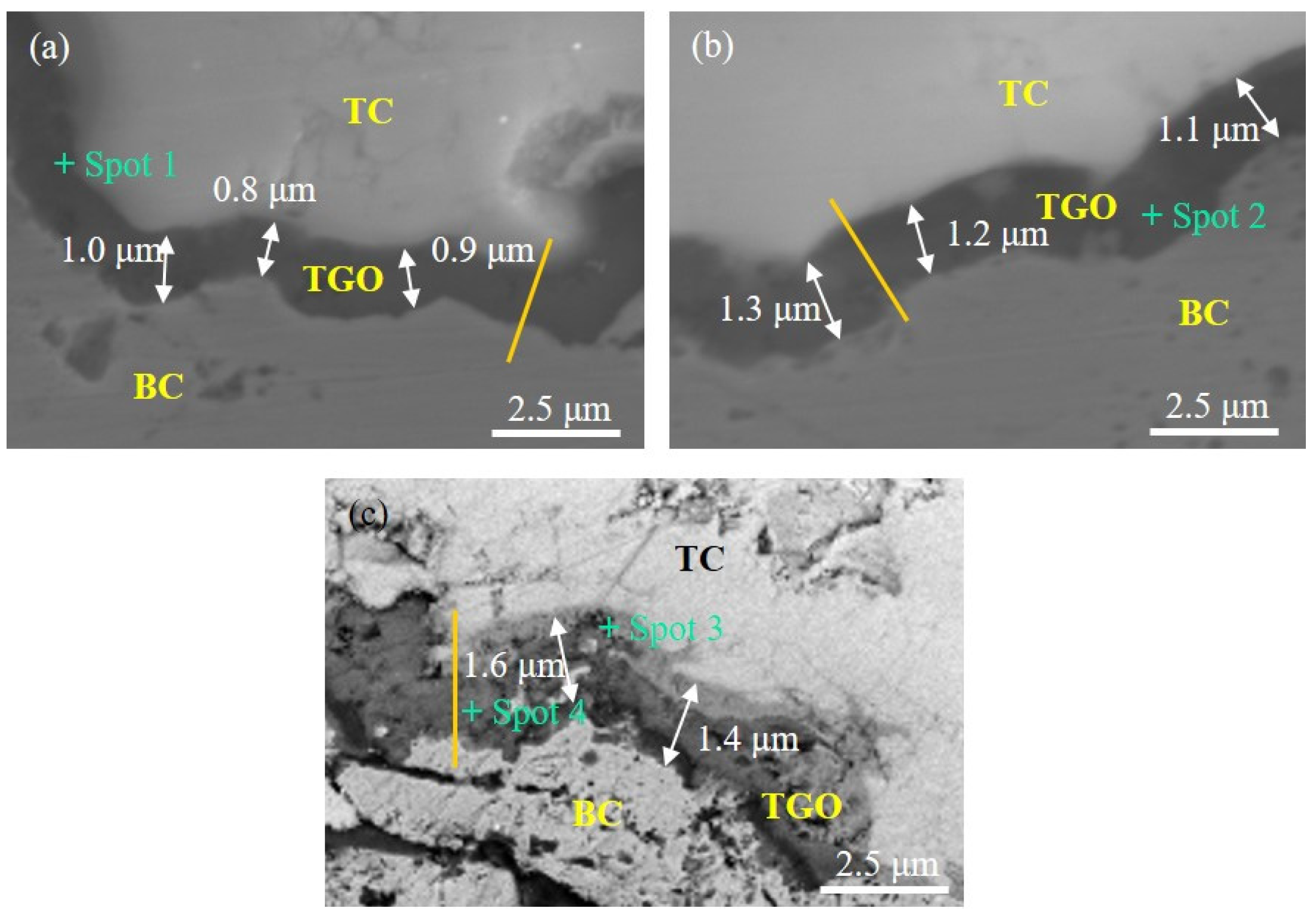
Figure 3 shows the cross-section morphologies of the oxidized specimens under different stresses at 900 °C for 100 h. In the case of the specimen without stress, a thin TGO layer in the NiCrAlY BC appears (Figure 3a), which has been obtained in the literature [25,26]. The average thickness of the TGO layer is about 0.9 μm. In the case of the specimen under 100 MPa tensile stress, a thicker oxide scale of approximately 1.2 μm is observed (Figure 3b), indicating that the induced tensile stress greatly promotes the oxidation of the NiCrAlY BC. The thickness of the TGO layer in the NiCrAlY BC increases to 1.5 μm with the introduction of the 100 MPa compressive stress (Figure 3c). Thus, compared with tensile stress, compressive stress further promotes the oxidation of the NiCrAlY BC. No crack is obtained in the TGO layer under different stresses, which means that the applied stress does not exceed the critical stress for oxide failure by cracking. Moreover, the surface morphology of the oxidized specimens without stress at 900 °C for 100 h is shown in Figure S1, similar to those of the oxidized specimens under tensile and compressive stresses (not shown). Hence, the effect of the external stress on the surface morphology of the TBC is limited.
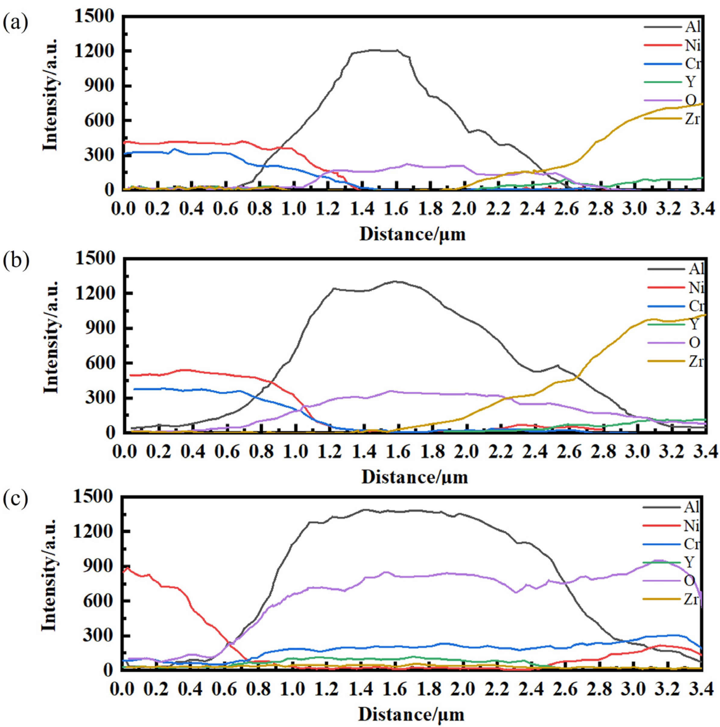
Figure 4 and Table 1 display the EDS line and spot composition diagrams of the specimens after oxidation at 900 °C for 100 h under different external loads. The main component of the TGO layer in the NiCrAlY BC without stress is Al2O3 (Figure 4a and Table 1), which is consistent with the reported literature [27,28]. A similar phenomenon is observed in the specimen under 100 MPa tensile stress (Figure 4b and Table 1). Thus, the external tensile stress possesses a limited effect on the composition of the TGO layer in NiCrAlY BC, while the TGO composition changes obviously when the specimen suffers from compressive stress according to the EDS results (Figure 4c and Table 1). Unlike the specimens without stress and under 100 MPa tensile stress, a two-layer TGO layer is formed in the oxidized specimen under 100 MPa compressive stress. More Ni and Cr elements are observed on the side close to the YSZ coating (upper TGO layer) with a thickness of about 0.3 μm. Then, the content of Ni and Cr elements decreases rapidly, and more Al2O3 appears (lower TGO layer). Since the upper TGO layer is not dense, the oxygen penetrates and reacts with Al to form more Al2O3. The change in the oxidation behavior of the NiCrAlY BC might be attributed to the various oxidation energy barriers of the elements under different stresses. Thus, the first-principles simulation was employed to explain the experimental results.

3.2. Ideal Oxidation of Al(111), Ni(111), and Cr(110) under Different Stresses

To more deeply understand the effect of the different stresses on the oxidation behavior of the NiCrAlY BC, simulations of the O2 molecule adsorption on the surfaces of the NiCrAlY BC under different stresses were carried out. To simplify the simulation, Al(111), Ni(111), and Cr(110) instead of NiCrAlY alloy were used. This simplification is reasonable because the main products are the oxides of Al, Ni, and Cr under different stresses (Figure 2). After geometry optimization, all low-symmetry structures relax into the high-symmetry ones and some high-symmetry vertical adsorption states are unstable.
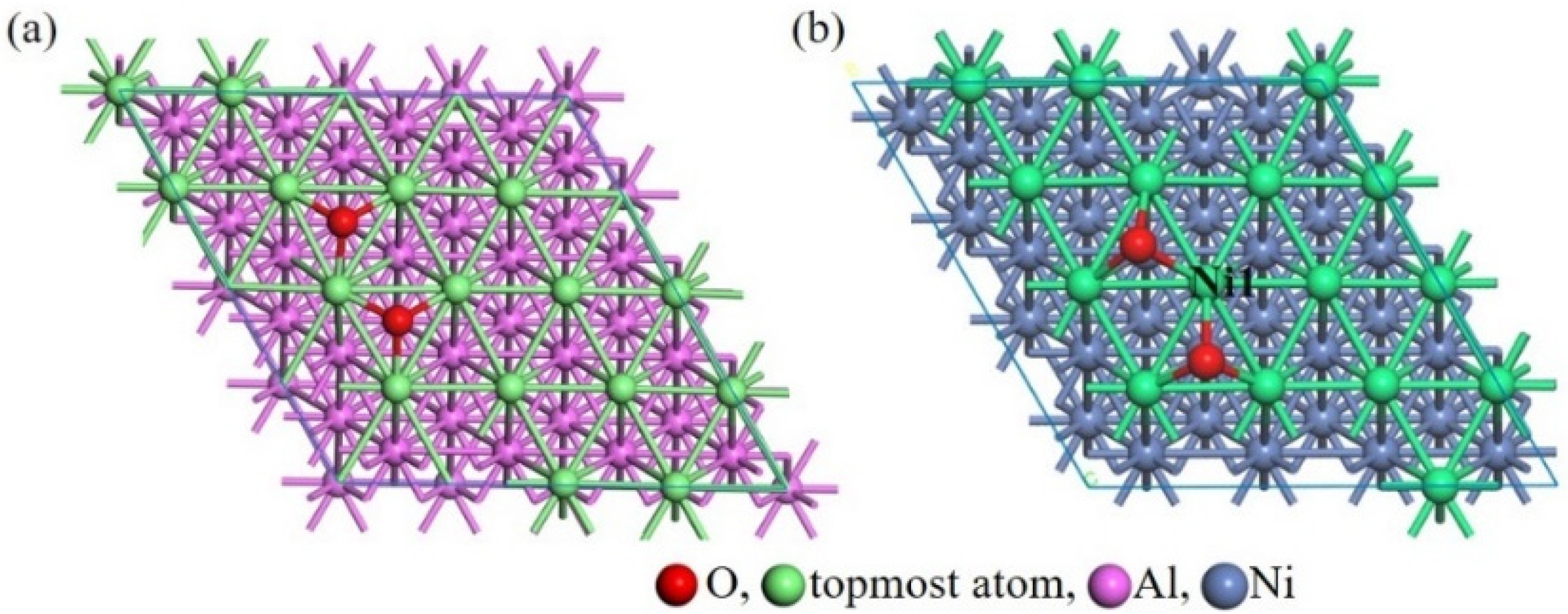
For the stress-free Al(111), the most stable structure with an adsorption energy of −12.43 eV is displayed in Figure 5a. For the Al(111) under tensile stress, the adsorption energy of the most stable structure is −12.39 eV, and its structure is similar to that of the oxidized stress-free Al(111). For the Al(111) under compressive stress, the most stable structure possesses the adsorption energy of −12.17 eV, resembling that of the oxidized stress-free Al(111). The O atom adsorbs at the threefold hollow connecting with three Al atoms in the most favorable adsorption configuration, thus reducing the number of dangling bonds on the surface. The negative adsorption energy implies that strong bonds are created between the adsorbed O atoms and the topmost Al atoms.
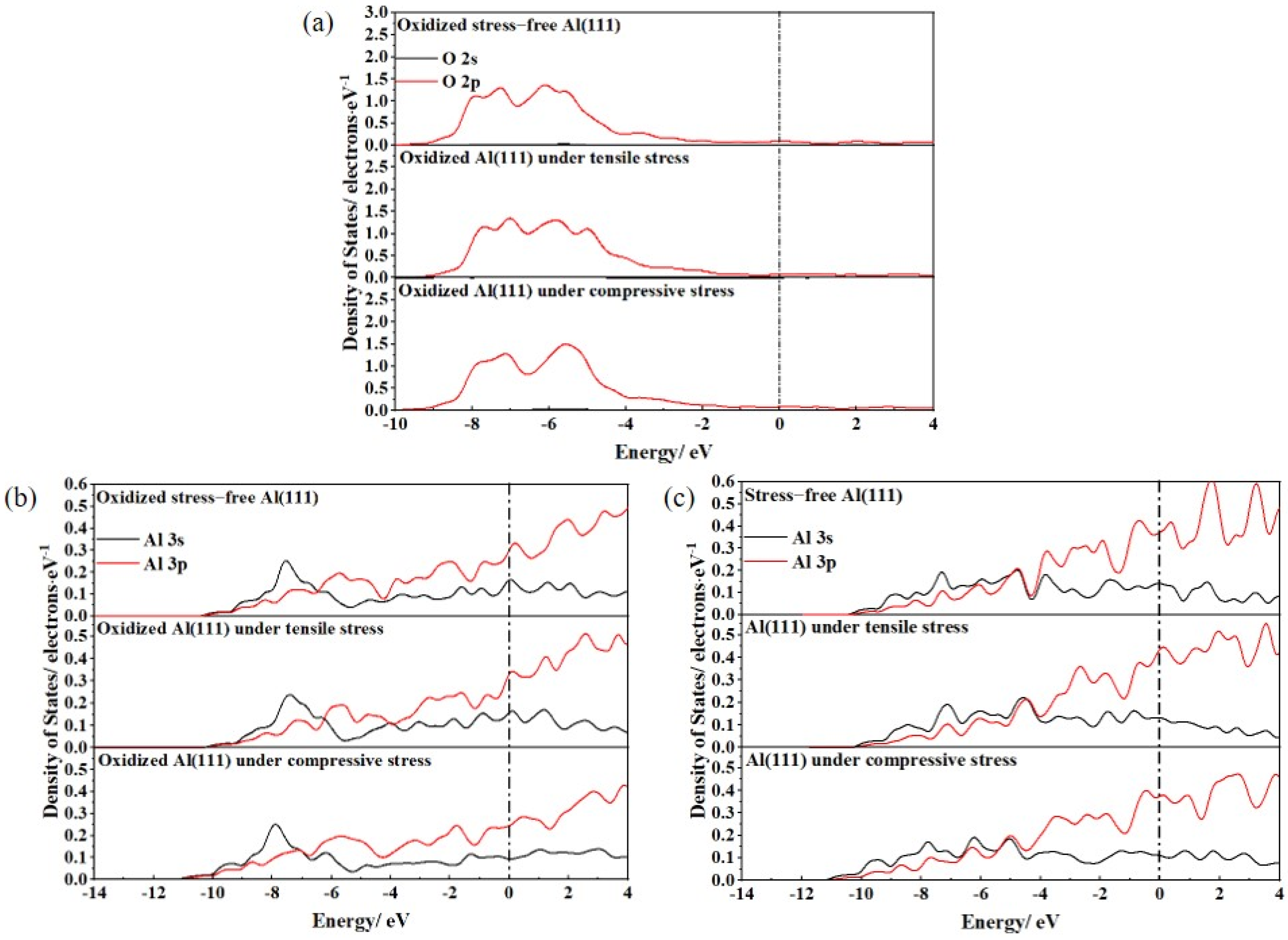
Comparing the adsorption energies, the O2 molecule prefers to adsorb on the stress-free Al(111) surface. Nevertheless, the difference in the adsorption energies of the various most stable structures is only 0.26 eV. Even though this is a small energetic difference, there are significant electronic differences among the three configurations, as shown in Figure 6. Figure 6a displays the partial density of states (PDOS) of the O atom in the oxidized Al(111) under different stresses. The O 2p-orbital peak appears at −5.21 eV in the oxidized stress-free Al(111), while it shifts to −4.98 eV in the oxidized Al(111) under tensile stress. The O 2p-orbital peak in the oxidized Al(111) under compressive stress is at the lowest energy of −5.58 eV, indicating that the O atom in the oxidized Al(111) under tensile stress is the least stable. Similarly, the oxidized Al 3s- and 3p-orbital peaks in the oxidized Al(111) under tensile stress possess the highest energies from −10.78 eV to the Fermi level, causing it to possess the lowest stability (Figure 6b), which is related to its initial state before oxidation. The Al 3s- and 3p-orbital peaks in the stress-free Al(111) surface appear between −11.04 eV and the Fermi level, while they shift to between −10.85 and the Fermi level in the Al(111) under tensile stress (Figure 6c). The Al 3s- and 3p-orbital peaks in the Al(111) under compressive stress are between −11.20 eV and the Fermi level, which implies that the Al atom in the Al(111) under tensile stress is the most unstable. Hence, the instability of the Al atom in the Al(111) under tensile stress might be the main reason for its easy oxidation.
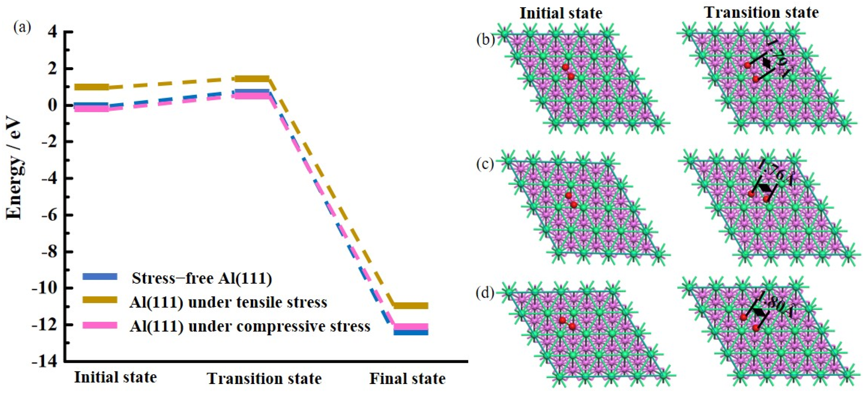
The interactions between the O2 molecules and the topmost Al atoms in the Al(111) under different stresses were investigated, and detailed positions for the interactions along the reaction paths with the lowest energy barriers are shown in Figure 7. All of the reaction paths possess similar transition states where the O2 molecule dissociates into O species; the O atom bonds to a surface Al atom, but remains unbonded for the remaining two Al atoms. The O2 molecule adsorption path on the stress-free Al(111) surface is characterized by an energy barrier of 0.52 eV (Figure 7a) and the O–O interatomic distance in the transition state structure is 1.79 Å (Figure 7b). The energy barrier for the O2 molecule adsorption on the surface of the Al(111) under tensile stress is 0.34 eV, 0.03 eV higher than that on the surface of the Al(111) under compressive stress (Figure 7a). The distance between the two O atoms is 1.76 Å in the transition state structure of the oxidized Al(111) under tensile stress (Figure 7c), while it is 1.80 Å in the transition state structure of the oxidized Al(111) under compressive stress (Figure 7d). Thus, O2 dissociation becomes the easiest on the surface of the Al(111) under tensile stress, agreeing well with the decreasing stability of the Al atom in the Al(111) under tensile stress (Figure 6). When Al is stretched, the instability of the Al atom increases, causing easier oxidation to occur, which supports the experimental results in which tensile stress results in the easier oxidation of Al (Figure 3).
The most stable configurations after the O2 molecule adsorption on the surface of the Ni(111) under different stresses are also observed, as shown in Figure 5b. The most stable structure after O2 molecule adsorption on the stress-free Ni(111) surface is similar to that on the Ni(111) under tensile or compressive stress (not shown). Each O atom bonds with the three topmost Ni atoms to decrease the dangling bonds on the surface. The lowest adsorption energy of −6.01 eV is obtained for the oxidized stress-free Ni(111), only 0.23 eV higher than that for the Ni(111) under tensile stress and 0.26 eV lower than that for the Ni(111) under compressive stress. The lowest adsorption energies of the O2 molecules on the surfaces of the Ni(111) under different stresses are much bigger (approximately 6 eV) than those on the surfaces of the Al(111) under different stresses. Thus, the interaction between the Ni atoms and O2 molecule is much weaker than that between the Al atoms and O2 molecule. In addition, the main difference among the three most stable structures of Ni(111) under different stresses is the various state of the oxidized Ni atoms. A charge transfer of 0.38 e from the oxidized Ni1 atom (marked in Figure 5b) to the O atom is observed after O2 molecule adsorption on the stress-free Ni(111) surface, leading to the formation of an O atom with a negative charge and a strong Ni1–O bond. This is a 0.39 e charge transfer from the oxidized Ni1 atom to the O atom after O2 molecule adsorption on the surface of the Ni(111) under tensile stress. The greatest charge transfer (0.45 e) from the oxidized Ni1 atom to the O atom occurs after O2 molecule adsorption on the surface of the Ni(111) under compressive stress, which means a strong interaction between the O atom and the Ni1 atom. Thus, the oxidized Ni1 atom in the Ni(111) under compressive stress possesses the most stability, which might cause the easiest oxidation of the Ni atom.
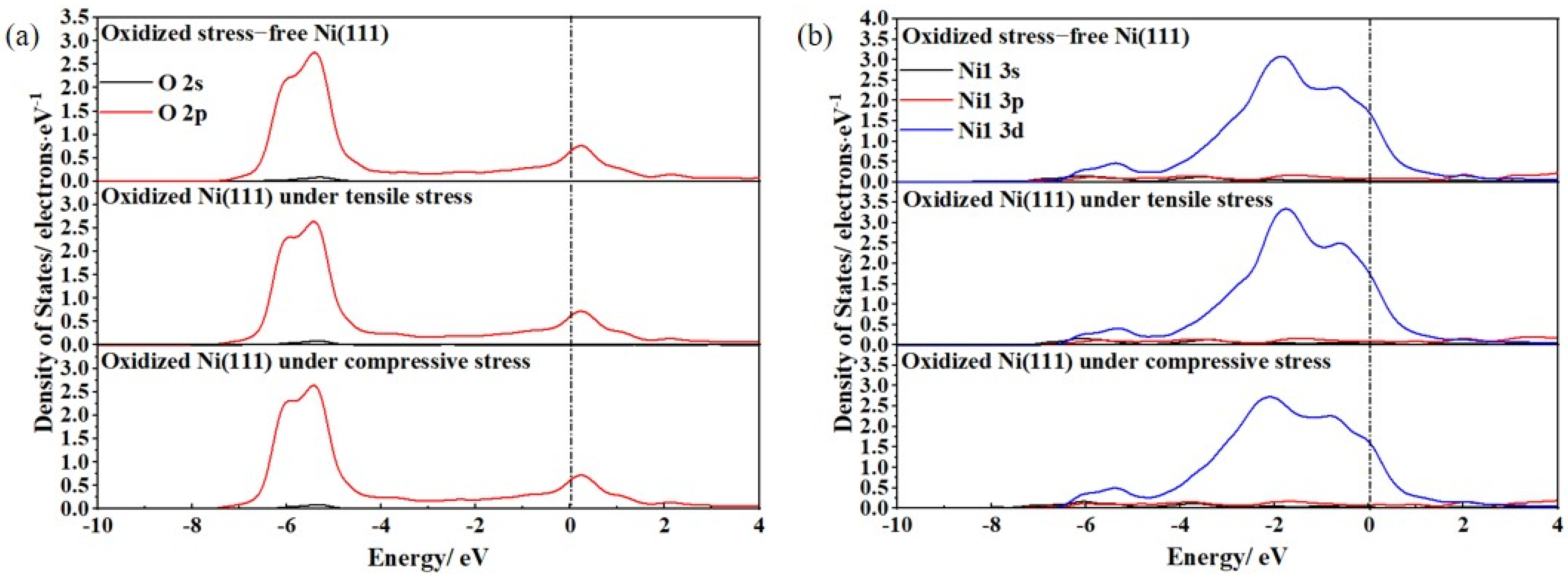
To further elucidate the oxidation behaviors of the Ni(111) under different stresses, we plotted the PDOS patterns of the Ni atom in the Ni(111) under different stresses before oxidation, as displayed in Figure 8. The Ni 3d orbital exerts a significant role in bonding (Figure 8b) in the Ni(111), different from the Al atom (Figure 6c), which might be a significant reason for their distinguishable oxidation behaviors (Figure 3). The Ni 3d orbital peak in the stress-free Ni(111) is located at −0.36 eV and shifts to the higher −0.24 eV in the Ni(111) under compressive stress, as opposed to the higher stabilization observed in Al(111) under compressive stress. The Ni 3d orbital peak in the Ni(111) under tensile stress appears at the highest energy of −0.17 eV, indicating that the Ni atom in the Ni(111) under tensile stress possesses the least stability, followed by the Ni atom in the Ni(111) under compressive stress, different from the Al atom in the Al(111) under compressive stress possessing the highest stability. Otherwise, all O 2s and 2p orbital peaks appear at the same position in the oxidized Ni(111) under different stresses after oxidation (Figure 8a), meaning similar O electronic structures. Therefore, the Ni 3d orbital with low bound exercises a major effect on the stability of the Ni atom under different stresses, which indicates that the oxidation behavior of Ni might be different from that of Al under different stresses.
A further study of the adsorption of an O2 molecule on the surface of the Ni(111) under different stresses was carried out. The key positions for the adsorption along the reaction path with the lowest energy barrier are displayed in Figure 9. All of the reaction paths possess similar transition states where the O2 molecule dissociates into two O atoms and the O atom bonds to a topmost Ni atom. The transition state of the O2 molecule adsorption on the stress-free Ni(111) surface has an energy barrier of 1.85 eV (Figure 9a) and the O–O distance in the transition state structure is 2.00 Å (Figure 9b). The O2 molecule adsorption path on the surface of the Ni(111) under tensile stress is characterized by an energy barrier of 1.78 eV, and the distance between the two O atoms in the transition state structure is 1.97 Å (Figure 9c). The transition state of the O2 molecule adsorption on the surface of Ni(111) under compressive stress is the one with the lowest energetic barrier, 1.50 eV, and the O–O distance in the transition state structure is 1.95 Å (Figure 9d). Hence, it is easiest for the O2 dissociation on the surface of the Ni(111) under compressive stress, which is consistent with the experimental results indicating easier oxidation occurrence for the Ni under compressive stress (Figure 3). Hence, as Ni suffers from compressive stress, the lowest energy is needed for the dissociation of the O2 molecule, causing it to be more easily oxidized.
The most stable configurations after the adsorption of the O2 molecules on the surfaces of the Cr(110) under different stresses are presented in Figure 10. In the case of the stress-free Cr(110), the most stable adsorption structure with an adsorption energy of −10.38 eV is displayed in Figure 10a. When the Cr(110) suffers from tensile stress, the adsorption energy of the most stable structure is −10.39 eV, and its structure is similar to that of the oxidized stress-free Cr(110), as shown in Figure 10b. For the Cr(110) under compressive stress, the most stable structure possesses the adsorption energy of −10.12 eV, and it is distinguished from that of the oxidized stress-free Cr(110) or Cr(110) under tensile stress. In the former, the O atom adsorbs at the fourfold hollow connecting with four Ni atoms due to the shorter distance between the Ni atoms, while in the latter two, it adsorbs at the threefold hollow connecting with three Ni atoms.
To further study the effect of stress on the electronic structure, the PDOS patterns of the Cr atom in the Cr(110) under different stresses are plotted and displayed in Figure 11b. The Cr 3d orbital is a great contributor to bonding, similar to the Ni atom (Figure 8b). The Cr 3d orbital peaks in the stress-free Cr(110) are between −4.88 eV and the Fermi level, while they appear between the higher −4.80 eV and Fermi level in the Cr(110) under compressive stress. The Cr 3d orbital peaks in the Cr(110) under tensile stress located between the highest energy of −4.71 eV and the Fermi level, which implies that the Cr atom in the Cr(110) under tensile stress possesses the least stability, followed by the Cr atom in the Cr(110) under compressive stress. The effect of stress on the characteristics of the Cr atom in Cr(110) is similar to that of the Ni atom in Ni(111). Thus, the oxidation behavior of Cr under different stresses might be similar to that of Ni under different stresses.
The adsorption behaviors of the O2 molecules on the surfaces of the Cr(110) under different stresses were analyzed further, and the PDOS patterns of the O atoms after adsorption are plotted and displayed in Figure 11a. The O 2p orbital peak appears at −5.74 eV in the oxidized stress-free Cr(110), while it shifts to −6.03 eV in the oxidized Cr(110) under compressive stress, meaning that the O atom in the oxidized Cr(110) under compressive stress is the more stable. Differently, two O 2p orbital peaks shift to the higher energies (−5.55 and −6.00 eV) in the oxidized Cr(110) under tensile stress. The various PDOS patterns might be due to the different stable configurations (Figure 10).
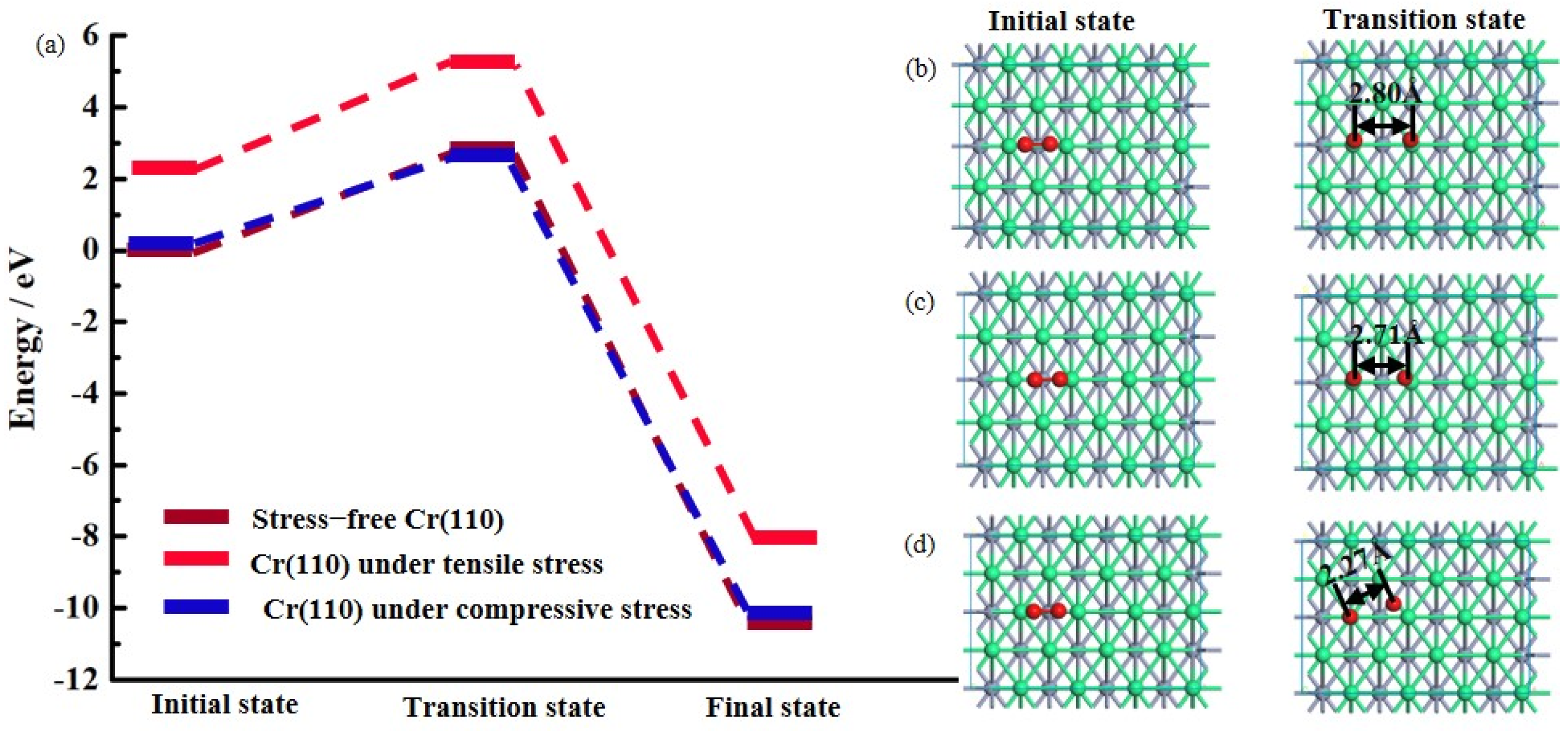
The interactions between the O2 molecules and the topmost Cr atoms in the Cr(111) under different stresses were investigated. The detailed positions for the interactions along the reaction paths with the lowest energy barriers are shown in Figure 12. The transition states in the Cr(110) under different stresses are varied, although the O2 molecule dissociates into O species in the transition states and the O atom bonds to a topmost Cr atom. The transition state of the O2 molecule adsorption on the stress-free Cr(110) surface has an energy barrier of 2.92 eV (Figure 12a) and the O–O distance in the transition state structure is 2.80 Å (Figure 12b). The barrier decreases to 2.76 eV on the surface of the Cr(110) under tensile stress and the distance between the two O atoms in the transition state structure is 2.71 Å (Figure 12c), which implies that the dissociation of the O2 molecule is feasible on the latter surface. The most favorable path for the adsorption of the O2 molecule occurs on the surface of the Cr(110) under compressive stress with an energy barrier of 2.63 eV and the O–O distance in the transition state structure is 2.27 Å (Figure 12d). Thus, the O2 molecule prefers to dissociate and adsorb on the surface of the Cr under compressive stress rather than that without stress and under tensile stress, resulting in it being the easiest to be oxidized.

4. Conclusions

TBCs subjected to oxidation under external stresses in air at 900 °C were examined using uniaxial tensile and compressive experiments. First-principles simulation was carried out to explain the experimental results. The results show that tensile stress enhances the oxidation of the NiCrAlY BC in air at 900 °C. The main composition of the oxidation layer is Al2O3. The phenomenon is caused by the easier adsorption of oxygen on the surface of the Al(111) under tensile stress with a lower energy barrier than that on the stress-free Al(111) surface. The stability of the Al atom under tensile stress is lower than that without stress. When the TBC suffers from compressive stress, the thickest TGO layer in the NiCrAlY BC appears, including the oxide of Al, Ni, and Cr, whereas the stability of the metal atom is higher than that under tensile stress. Hence, the effect of the stability of metal atoms does not always appear to be the most important. O2 molecule dissociation becomes the easiest on the surface of Ni(111) and Cr(110) under compressive stress because of the effect of the 3d orbital. These results show that external loads affect the binding state of electrons, causing changes in their oxidation behavior. Tensile stress has the greatest impact on the bonding properties of the Al element, while compressive stress contributes the most to the binding state of the Ni and Cr elements. By understanding how the external loads are correlated with the bonding properties of the elements during the oxidation process, we can design the composition of the BC under external loads.

Supplementary Materials

The following supporting information can be downloaded at: https://www.mdpi.com/article/10.3390/coatings13050862/s1, Figure S1: Surface image of the specimens without stress after oxidation at air at 900 °C for 100 h.

Author Contributions

Conceptualization, C.C. and M.N.; methodology, Z.T. and Y.C.; investigation, C.C.; writing—original draft preparation, C.C., M.N. and C.L.; writing—review and editing, L.Y. and Y.Z.; project administration, C.C.; funding acquisition, L.Y. and Y.Z. All authors have read and agreed to the published version of the manuscript.

Funding

This work was supported by the Fundamental Research Funds for the Central Universities of China (Grant Nos. 20101237677 and 10251220003), the National Basic Research Program of China (Grant Nos. 11890684, 52102142, and 12002054), and the Innovation Capability Support Program of Shaanxi (Program No. 2022TD-28).

Institutional Review Board Statement

Not applicable.

Informed Consent Statement

Not applicable.

Data Availability Statement

Data are contained within the article.

Conflicts of Interest

The authors declare no conflict of interest.

References

  1. Guo, L.; Gao, Y.; Cheng, Y.; Sun, J.; Ye, F.; Wang, L. Microstructure design of the laser glazed layer on thermal barrier coatings and its effect on the CMAS corrosion. Corros. Sci. 2021, 192, 109847. [Google Scholar] [CrossRef]
  2. Lyu, G.; Song, D.; Kim, J.; Lu, Z.; Yang, B.; Yang, S.; Byeun, Y.; Jung, Y. Multidisciplinary approach for investigating the hot corrosion behavior of thermal barrier coatings. J. Eur. Ceram. Soc. 2021, 41, 324–333. [Google Scholar] [CrossRef]
  3. Cong, L.; Li, W.; Wang, J.; Gu, S.; Zhang, S. High-entropy (Y0.2Gd0.2 Dy0.2Er0.2Yb0.2)2Hf2O7 ceramic: A promising thermal barrier coating material. J. Mater. Sci. Technol. 2022, 101, 199–204. [Google Scholar] [CrossRef]
  4. Xu, G.N.; Yang, L.; Zhou, Y.C. Investigating the Interface Cracking Mechanism of CMAS-Corroded Thermal Barrier Coatings Based on the Cohesive Zone Model. Corros. Sci. 2022, 204, 110337. [Google Scholar] [CrossRef]
  5. Padture, N.P. Thermal barrier coatings for gas-turbine engine applications. Science 2002, 296, 280–284. [Google Scholar] [CrossRef] [PubMed]
  6. Li, S.; Xu, M.M.; Zhang, C.Y.; Bao, Z.B.; Yang, Y.F.; Zhu, S.L.; Wang, F.H. Effect of pre-oxidation on the failure mechanisms of EB-PVD thermal barrier coatings with (Ni, Pt)Al bond coats. Corros. Sci. 2021, 193, 109873. [Google Scholar] [CrossRef]
  7. Deng, S.; He, G.; Yang, Z.; Wang, J.; Li, J.; Jiang, L. Calcium-magnesium-alumina-silicate (CMAS) resistant high entropy ceramic (Y0.2Gd0.2Er0.2Yb0.2Lu0.2)2Zr2O7 for thermal barrier coatings. J. Mater. Sci. Technol. 2022, 107, 259–265. [Google Scholar] [CrossRef]
  8. Torkashvand, K.; Poursaeidi, E.; Mohammadi, M. Effect of TGO thickness on the thermal barrier coatings life under thermal shock and thermal cycle loading. Ceram. Int. 2018, 44, 9283–9293. [Google Scholar] [CrossRef]
  9. Shen, Z.; He, L.; Mu, R.; Xu, Z.; Huang, G. Effects of gradient transitional layer on thermal cycling life and failure of LaZrCeO/YSZ thermal barrier coatings. Corros. Sci. 2020, 163, 108221–108224. [Google Scholar] [CrossRef]
  10. Wei, Z.Y.; Liu, Y.; Cheng, B.; Tahir, A. Influence of non-uniform feature of thermally grown oxide thickness on the local stress state and cracking behavior in TBC. Surf. Coat. Technol. 2022, 443, 128607. [Google Scholar] [CrossRef]
  11. Zhang, R.; Zhang, X.; Xing, C.; Hu, L.; Zhao, X. Preparation of long-lifetime thermal barrier coatings and toughening mechanism by using hierarchy structured zirconia-based microspheres. J. Eur. Ceram. Soc. 2021, 41, 4625–4636. [Google Scholar] [CrossRef]
  12. Xu, M.M.; Li, Y.Y.; Zhang, C.Y.; Jiang, C.Y.; Bao, Z.B.; Zhu, S.L.; Wang, F.H. Synergistic effect of Re-base diffusion barrier and Pt modification on the oxidation behaviour of NiCrAlY coatings. Corros. Sci. 2022, 194, 109919. [Google Scholar] [CrossRef]
  13. Zhang, X.; Watanabe, M.; Kuroda, S. Effects of residual stress on the mechanical properties of plasma-sprayed thermal barrier coatings. Eng. Fract. Mech. 2013, 110, 314–327. [Google Scholar] [CrossRef]
  14. Yang, L.; Yang, F.; Long, Y.; Zhao, Y.; Xiong, X.; Zhao, X.; Xiao, P. Evolution of residual stress in air plasma sprayed yttria stabilised zirconia thermal barrier coatings after isothermal treatment. Surf. Coat. Technol. 2014, 251, 98–105. [Google Scholar] [CrossRef]
  15. Yu, Q.M.; He, Q. Effect of material properties on residual stress distribution in thermal barrier coatings. Ceram. Int. 2018, 44, 3371–3380. [Google Scholar] [CrossRef]
  16. Lin, A.Q.; Liu, G.W.; Yu, X.X.; Chang, R.; Feng, Q. Comprehensive investigations on fluid flow and heat transfer characteristics of a high-speed rotating turbine disk cavity system of aero-engine. Int. Commun. Heat Mass Transf. 2022, 136, 106170. [Google Scholar] [CrossRef]
  17. Lin, A.Q.; Ma, J.L.; Fan, G.Y.; Lei, Z.; Fawzy, H.; Liu, G.W. Aerothermal performances of a rotating turbine disk cavity with non-uniform wall temperature profiles in an aero-engine. Therm. Sci. Eng. Prog. 2023, 38, 101582. [Google Scholar] [CrossRef]
  18. Tan, Z.Y.; Yang, Z.H.; Zhu, W.; Yang, L.; Zhou, Y.C.; Hu, X.P. Mechanical properties and calcium-magnesium-alumino-silicate (CMAS) corrosion behavior of a promising Hf6Ta2O17 ceramic for thermal barrier coatings. Ceram. Int. 2020, 46, 25242–25248. [Google Scholar] [CrossRef]
  19. Zhu, W.; Li, Z.Y.; Yang, L.; Zhou, Y.C.; Wei, J.F. Real-time detection of CMAS corrosion failure in APS thermal barrier coatings under thermal shock. Exp. Mech. 2020, 60, 775–785. [Google Scholar] [CrossRef]
  20. Perdew, J.P.; Burke, K.; Ernzerhof, M. Generalized Gradient Approximation Made Simple. Phys. Rev. Lett. 1998, 77, 3865–3868. [Google Scholar] [CrossRef]
  21. Clark, S.; Segall, M.; Pickard, C.; Hasnip, P.; Probert, M.; Refson, K.; Payne, M. First principles methods using CASTEP. Z. Fur Krist. 2005, 220, 567–570. [Google Scholar] [CrossRef]
  22. Cheng, C.; Li, H.; Fu, Q. Effect of stretching on the initial oxidation of 3C-SiC nanowire by first-principle simulation. Appl. Surf. Sci. 2019, 483, 170–177. [Google Scholar] [CrossRef]
  23. Henkelman, G.; Jonsson, H. Improved tangent estimate in the nudged elastic band method for finding minimum energy paths and saddle points. J. Chem. Phys. 2000, 113, 9978–9985. [Google Scholar] [CrossRef]
  24. Henkelman, G.; Uberuaga, B.P.; Jo Nsson, H. A climbing image nudged elastic band method for finding saddle points and minimum energy paths. J. Chem. Phys. 2000, 113, 9901–9904. [Google Scholar] [CrossRef]
  25. Yu, C.; Liu, H.; Jiang, C.; Bao, Z.; Zhu, S.; Wang, F. Modification of NiCoCrAlY with Pt: Part II. Application in TBC with pure metastable tetragonal(t’) phase YSZ and thermal cycling behavior. J. Mater. Sci. Technol. 2019, 35, 350–359. [Google Scholar] [CrossRef]
  26. Chen, Z.; Jia, W.; Zhao, K.; Fang, L. Comparison of stress evolution under TGO growth simulated by two different methods in thermal barrier coatings. Ceram. Int. 2020, 46, 2915–2922. [Google Scholar] [CrossRef]
  27. RöSler, J.; BäKer, M.; Aufzug, K. A parametric study of the stress state of thermal barrier coatings: Part I: Creep relaxation. Acta Mater. 2004, 52, 4809–4817. [Google Scholar]
  28. Shen, Q.; Yang, L.; Zhou, Y.C.; Wei, Y.G.; Zhu, W. Effects of growth stress in finite-deformation thermally grown oxide on failure mechanism of thermal barrier coatings. Mech. Mater. 2017, 114, 228–242. [Google Scholar] [CrossRef]
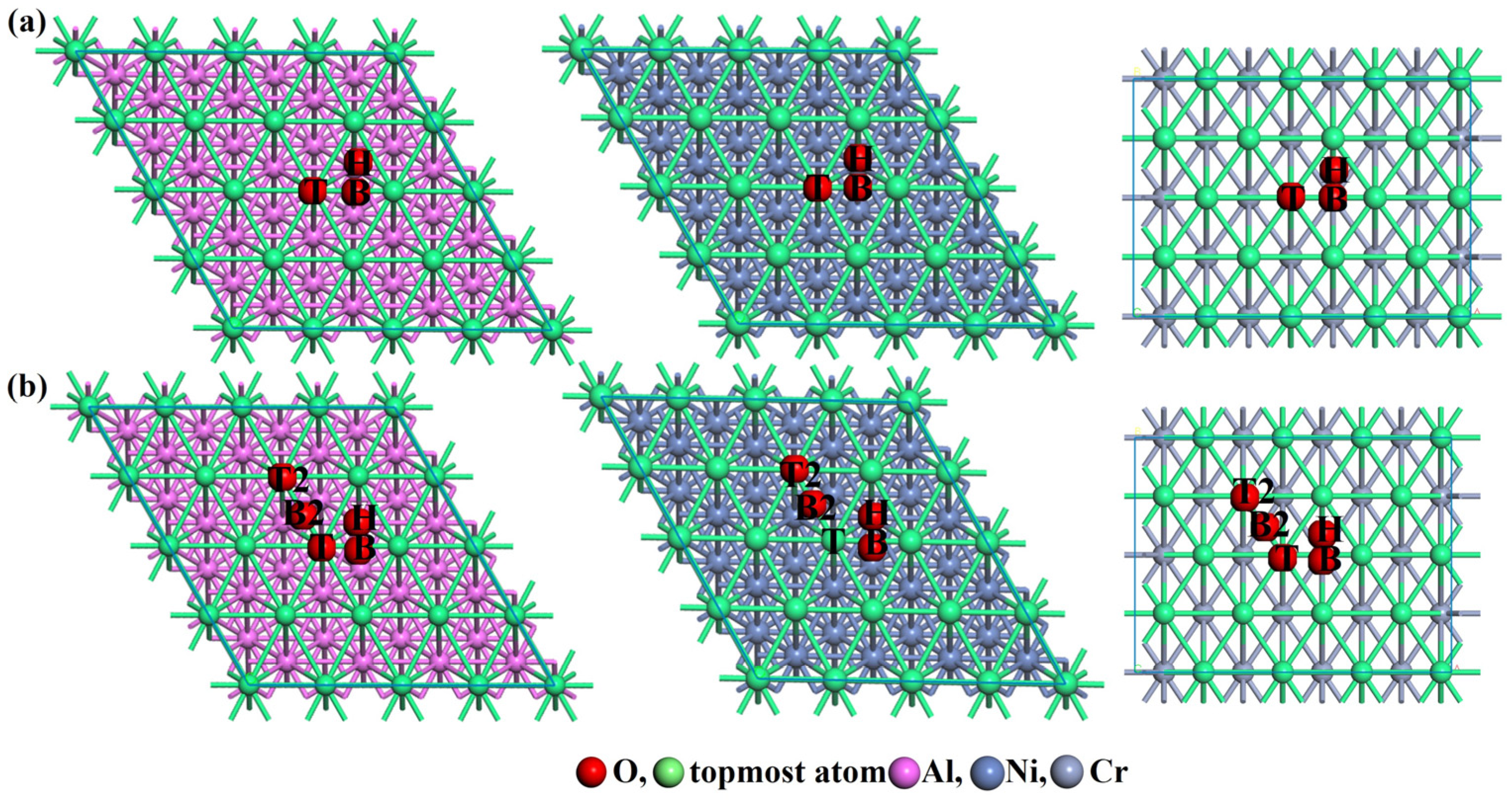
Figure 1. (a) Three adsorption sites (Top site (T), Bridge site (B) and Hollow site (H)) on the surface of the stress-free Al(111), Ni(111), and Cr(110), and (b) five adsorption sites on the surface of Al(111), Ni(111) and Cr(110) under external stress.
Coatings 13 00862 g001
Figure 2. XRD patterns of the oxidized specimens under different stresses at 900 °C for 100 h.
Coatings 13 00862 g002
Figure 3. SEM cross-section images of the specimens after oxidation at 900 °C for 100 h (a) without stress, (b) under 100 MPa tensile stress, and (c) under 100 MPa compressive stress.
Coatings 13 00862 g003
Figure 4. EDS line composition diagrams of the specimens after oxidation at 900 °C for 100 h (a) without stress, (b) under 100 MPa tensile stress, and (c) under 100 MPa compressive stress (yellow line in Figure 3a–c).
Coatings 13 00862 g004
Figure 5. Most stable structures for the oxidized stress-free (a) Al(111) and (b) Ni(111).
Coatings 13 00862 g005
Figure 6. Partial density of states (PDOS) patterns of the (a) O, (b) Al, and (c) oxidized Al atoms in the Al(111) under different stresses. The vertical lines represent the position of the Fermi levels (set to zero).
Coatings 13 00862 g006
Figure 7. (a) Comparison of the O2 molecule adsorption processes on the surface of the Al(111) under different stresses. Only the snapshots of the key states (initial states and transition states) for the O2 molecule adsorption on the surface of the (b) stress-free Al(111), (c) Al(111) under tensile stress, and (d) Al(111) under compressive stress are displayed.
Coatings 13 00862 g007
Figure 8. PDOS patterns of the (a) O atom in the oxidized Ni(111) under different stresses and (b) Ni atom in the Ni(111) under different stresses. The vertical lines represent the position of the Fermi levels (set to zero).
Coatings 13 00862 g008
Figure 9. (a) Comparison of the O2 molecule adsorption processes on the surface of the Ni(111) under different stresses. Only the snapshots of the key states (initial states and transition states) for O2 molecule adsorption on the surface of the (b) stress-free Ni(111), (c) Ni(111) under tensile stress, and (d) Ni(111) under compressive stress are displayed.
Coatings 13 00862 g009
Figure 10. Most stable structure for the oxidized (a) stress-free Cr(110), (b) Cr(110) under tensile stress, and (c) Cr(110) under compressive stress.
Coatings 13 00862 g010
Figure 11. PDOS patterns of the (a) O atom in the oxidized Cr(110) under different stresses and (b) Cr atom in the Cr(110) under different stresses before oxidation. The vertical lines represent the position of the Fermi levels (set to zero).
Coatings 13 00862 g011
Figure 12. (a) Comparison of the O2 molecule adsorption processes on the Cr(110) under different stresses. Only the snapshots of the key states (initial states and transition states) for O2 molecule adsorption on the surface of the (b) stress-free Cr(110), (c) Cr(110) under tensile stress, and (d) Cr(110) under compressive stress are displayed.
Coatings 13 00862 g012
Table 1. EDS spot composition of the TGO layer in the specimens after oxidation at 900 °C for 100 h under different stresses (spots in Figure 3a–c).
SpotNiCrAlYO
Composition/at. %
12.73.535.20.058.6
23.14.233.70.059.0
39.616.422.10.351.6
42.33.936.90.056.9
Disclaimer/Publisher’s Note: The statements, opinions and data contained in all publications are solely those of the individual author(s) and contributor(s) and not of MDPI and/or the editor(s). MDPI and/or the editor(s) disclaim responsibility for any injury to people or property resulting from any ideas, methods, instructions or products referred to in the content.