Article

Study on the Wear Modes of PVD Films Using Different Concentrations of Al2O3 Abrasive Particles and Textured Rotating Balls

by
Gustavo Filipe Pinto
1,2,*,
Andresa Baptista
1,2,
Vitor F. C. Sousa
1,2,
Francisco J. G. Silva
1,2,
Manuel Evaristo
3 and
Filipe Fernandes
1,3,*
1
ISEP, Polytechnic of Porto, Rua Dr. António Bernardino de Almeida, 431, 4249-015 Porto, Portugal
2
Associate Laboratory for Energy, Transports and Aerospace (LAETA-INEGI), Rua Dr. Roberto Frias, 400, 4200-465 Porto, Portugal
3
CEMMPRE-Center for Mechanical Engineering Materials, Processes Department of Mechanical Engineering, University of Coimbra, Rua Luís Reis Santos, 3030-788 Coimbra, Portugal
*
Authors to whom correspondence should be addressed.
Coatings 2023, 13(3), 628; https://doi.org/10.3390/coatings13030628
Submission received: 16 February 2023 / Revised: 7 March 2023 / Accepted: 14 March 2023 / Published: 16 March 2023
(This article belongs to the Section Surface Characterization, Deposition and Modification)

Abstract

:
Abrasive wear is a wear mechanism that results in a loss of material from the interaction of a surface with hard particles. This type of wear is frequently found in the surface of machining tools. Microscale abrasion equipment is often used to characterize the resistance to abrasive wear of a surface. The different parameters able to control micro-abrasion wear tests, such as ball rotation, sliding distance between ball and surface sample, abrasive slurry concentration, normal load acting on the sample, and abrasive flow rate over the sample, have been widely studied. The combination of different variables, including sliding distance, concentration of abrasive particles, their hardness, and size of abrasive particles, promotes the transition between two-body, three-body, or mixed abrasive wear modes. However, the influence of the ball surface on the dragging of abrasive particles, which is reflected in the wear modes, is still poorly studied. One of the variables possible to control and less studied is the influence of the ball surface texture on the dragging of abrasive particles in micro-abrasion wear tests. This work intends to correlate the effect of different testing times (500, 1000, and 1500 cycles) and different concentrations of 3 μm Al2O3 abrasive slurry (25, 35, and 45 g/100 mL) on the micro abrasion resistance of a TiN thin coating film, using balls of AISI 52100 steel whose texture and roughness were prepared by 60 s chemical etching. The rotation speed of each test was 80 rpm, applying a normal load of 2 N. Subsequently, the craters were carefully analyzed using SEM to evaluate the transition of the wear mode as a function of the applied load, the abrasive particle concentration, and the sliding distance. The textured ball tracks were observed via SEM to assess the particle dynamics. The results showed that, contrarily to what is reported in the literature regarding wear modes where rolling is promoted with increasing abrasive concentration, in this work grooving took place instead. This is a result of the rough balls use in the experiments which, due to the embedment of abrasive particles in the ball grooves, promotes the abrasion mechanism. The higher the abrasive concentration, the higher the grooving mechanism, since more particles are available to scratch the surface.

1. Introduction

The development of new hard coatings for protecting the machining tools surface is permanent. This induces the constant need for an adequate characterization of wear resistance. One of the most common forms of wear and tear is abrasion. Given the reduced thickness that usually characterizes thin solid films produced using PVD and CVD techniques [1,2], it becomes necessary to develop methodologies for testing these coatings that are expeditious and allow reliable/reproducible results [3]. This gap was identified by Rutherford and Hutchings [4,5] in the late 1990s, and a new test methodology, micro-scale abrasion, emerged. This equipment is also known as a ball-cratering device as it produces a crater caused by the action of a ball animated with a rotating motion, assisted by an abrasive slurry consisting of distilled water and a concentration of a selected abrasive powder. This slurry is constantly stirred to ensure the necessary homogeneity of the abrasive mixture to the contact zone between the ball and the flat sample surface [6]. Studies on this new test methodology were multiplied due to its flexibility, relatively small and cheap equipment, and the very affordable price of the necessary samples [7]. To establish a universal procedure for performing the tests and interpreting the results, Gee et al. [8] originated the definition of a standard that would regulate this type of test. After this step, the same authors felt the need to analyze the reproducibility and accuracy of the results obtained in order to validate the proposed procedure [9]. In that study, they found that the analysis of craters produced using a microscope allowed a greater reproducibility of results than using profilometry, with a maximum difference of 2% in the results obtained in 14 different laboratories under the same test conditions. However, this opinion was not shared by the entire scientific community. Schiffmann et al. [10] reported serious difficulties in measuring craters that had reached the substrate, stating that using a profilometer would be more appropriate in this case. In parallel, Kusano et al. [11] established a methodology for the treatment of data resulting from this type of test in an attempt to improve the accuracy and reproducibility of the results. Cozza [12] investigated the influence of normal load and abrasive particles concentration on the friction coefficient between the ball and the sample surface, concluding that there is no direct relationship between normal load or abrasive concentration on the friction coefficient measured under each set of test conditions. Using a monolayer film of TiN and another composed of two TiN layers, Batista et al. [13] sought to find differences in the wear mechanism in the transition between layers; they observed only grooving in the monolayer film, while in the multilayer film a mixture of rolling and grooving was observed. The use of different abrasive particle materials has been studied by Silva et al. [14], specifically diamond, alumina, and silicon carbide, to identify the particles that promote more defined craters. The study showed that diamond particles gave rise to the most well-defined craters, primarily due to a lower gap between the levels of hardness presented by coating and abrasive particles.
Ardila et al. [15] investigated the possible influence of the ball material on the dragging of particles that induce micro-abrasion on the sample’s surface. They concluded that balls made of harder materials gave rise to higher coefficients of friction, resulting in less uniform craters and regular spacing between grooves. Ardila’s study has been recently extended by Pinto et al. [16], who used different ball materials. They showed that AISI 304 stainless steel has proved to be more efficient in dragging the abrasive particles throughout the contact, revealing that abrasive particles easily remain completely embedded. Moreover, rolling wear mode was predominant when using SS AISI 304, while grooving was prevalent when using AISI 52100 balls. Baptista et al. [17] studied the influence of the surface roughness of the balls used in the micro-abrasion test, using AISI 52100 steel balls provided with different etching times, which induced different surface textures in the balls. This study allowed the authors to conclude that the volume of worn material grows slowly but consistently with the increase in normal load and the ball’s etching time. Ardila et al. [18] have investigated the evolution and role played by the topography of the ball, concluding that there are topography changes over time during the test, increasing the contact area and the roughness surface, thereby dragging more abrasive particles across the contact area.
Another study performed by Esteves et al. [19], investigating the influence of the ball rotation on the results, demonstrated that, when increasing the rotation speed of the ball, there is a decrease in the wear coefficient. They also observed an increase in the number of abrasive particles embedded on the sample’s surface.
Stack and Mathew [20] used micro-abrasion to compare the wear behavior of WC/Co coatings with uncoated stainless steels, concluding that stainless steel performs better than WC/Co coating, primarily under elevated normal loads. Silva et al. [21] used micro-abrasion to study the wear performance of diamond coatings produced by CVD. Using diamond abrasive particles, they obtained relatively low wear rates, confirming the excellent performance of this type of coating. Micro-abrasion has also been used to evaluate the wear performance of NCD (Nanocrystalline Diamond) produced by CVD [22]. Rodríguez-Castro et al. [23] compared the wear performance of uncoated CoCrMo substrates with CoB/Co2B coated ones using micro-abrasion. In addition, they mapped the tests conditions that have promoted a change from grooving to rolling wear modes. The friction coefficient of some well-known PVD coatings, such as TiN and TiC, has also been evaluated by using micro-abrasion-tests and analyzing tangential and normal forces during the tests. In one of these studies, Cozza et al. [24] concluded that the friction coefficient of those films ranges from 0.4 to 0.9. The same authors also concluded that the wear rate is inversely proportional to the hardness of the coating. Silva et al. [25] compared TiAlN and TiAlSiN coatings produced by the PVD technique, concluding that the addition of 5% Si is not enough to clearly improve the micro-abrasion wear resistance of the coating. Martinho et al. [26] investigated the micro-abrasion performance of TiAlCrSiN thin coatings producing by PVD and compared its behavior with uncoated pre-treated tool steel used in the molding injection of 30% glass-fiber reinforced plastics. They concluded that TiAlCrSiN improves the abrasion wear resistance of the surface by 50%. Silva et al. [27] investigated the wear behavior of multi-layered CrN/CrCN/DLC for its application in molds devoted to the injection of glass-fiber reinforced plastics. They concluded that the results obtained in the micro-abrasion tests cannot be directly compared with the results obtained in inserts placed into the mold. Moreover, in a comparative wider study subsequently developed by the same authors [3] concerning a group of different coatings, micro-abrasion tests showed that TiAlN monolayer coating presents the best micro-abrasion wear behavior.
Micro-abrasion has also been used to test the abrasion resistance of bulk (not coated) materials. Stachowiak et al. [28] investigated the micro-abrasion behavior of high Cr content white cast irons. They revealed that the matrix of white cast irons is preferably worn, while carbides were more resistant and stood out. Recently, Moreira [29] used micro-abrasion tests to determine the benefits obtained by the inclusion of WC-MMCs (Tungsten Carbide Metal Matrix Composites) into low carbon cast steels. The results showed that an increased wear resistance of 39% could be obtained with the new structure. Polymeric coatings [30] have also been tested using micro-abrasion wear tests with very promising results. Nickel superalloys produced using plasma transferred arc, used in the protection of the surface of molds for the glass industry, have also been studied for abrasion resistance using different applied loads and abrasive slurry concentrations [31]. Results showed that the specific wear rate essentially depends on the wear mechanisms (rolling or grooving) and not on the testing conditions.
Titanium nitride (TiN) hard coating deposited by sputtering has brought about one of the most significant technological advances in the development of modern tools. In the early years of PVD hard coating, TiN was essentially the only coating developed until 1980 [32]. Although many other PVD hard coatings were later developed, TiN coating remains one of the most important since it is a simple coating system, is easily to produce, and can be reused. It is also often used to coat the surface of machining tools. Despite the immense number of tribological studies conducted on this coating system, studies regarding its abrasion performance using micro-scale abrasion resistance remain scarce. Studies focused on tests conducted against counterparts with induced roughness, tests duration and the effect of abrasive concentrations of slurry on the wear mechanism, and specific wear rate are still missing in the literature.
In this work, the effect of different test times and different concentrations of abrasive slurry (25, 35 and 45 g/100 mL) on wear resistance of a TiN film using an AISI 52100 steel balls whose texture and roughness were prepared by chemical etching were studied. The results are discussed in terms of the effect of the roughness of the ball, concentration of abrasive slurry on the dominant wear mechanisms, and specific wear rate of the coating.

2. Materials and Methods

2.1. Material

2.1.1. Substrates and Balls Used in the Experiments

Uddeholm CALMAX steel (chromium-molybdenum-vanadium steel alloy) was used as substrate, with Young’s modulus of 210 GPa and hardness of 1.863 GPa. The chemical composition of the samples is shown in Table 1. Coupons with dimensions of 28 mm × 25 mm × 4 mm (width × length × thickness) were machined, followed by a heat treatment, annealing at 650 °C for 2 h, to remove stresses in the material during machining. Then, an additional heat treatment was carried out at 960 °C, followed by oil quenching, to harden the substrate and ensure its hardness was closer to the coating to be deposited. The final average hardness of the samples was 9.729 ± 0.049 GPa. After the heat treatments, a surface cleaning was performed, followed by a grinding operation using 400, 800, and 1200 grit sandpaper. Then the surface was polished using a diamond suspension until a mirror-like aspect was achieved (Ra of 0.0256 ± 0.002 µm). During the roughness analysis procedure, five measurements were performed in two orthogonal directions, obtaining an average value and the corresponding standard deviation. Subsequently, all samples went on to the next process: the deposition of titanium nitride (TiN) coating.
To carry out the microabrasion tests, polished AISI 52100 steel balls with a diameter of 25.4 mm were acquired. The balls underwent an ultrasonic cleaning process with acetone for 15 min. After cleaning, the balls were etched with a 4% Nital solution for 60 s, following the guidelines of the authors’ previous work [16,17], to increase the surface roughness. Its texture, resulting from the attack, can be observed in [17]. Using a scanning electron microscope (SEM), the balls were observed in their natural state (in as supplied conditions) and after having been etched by Nital 4% for 60 s.

2.1.2. Abrasive Particles Characterization

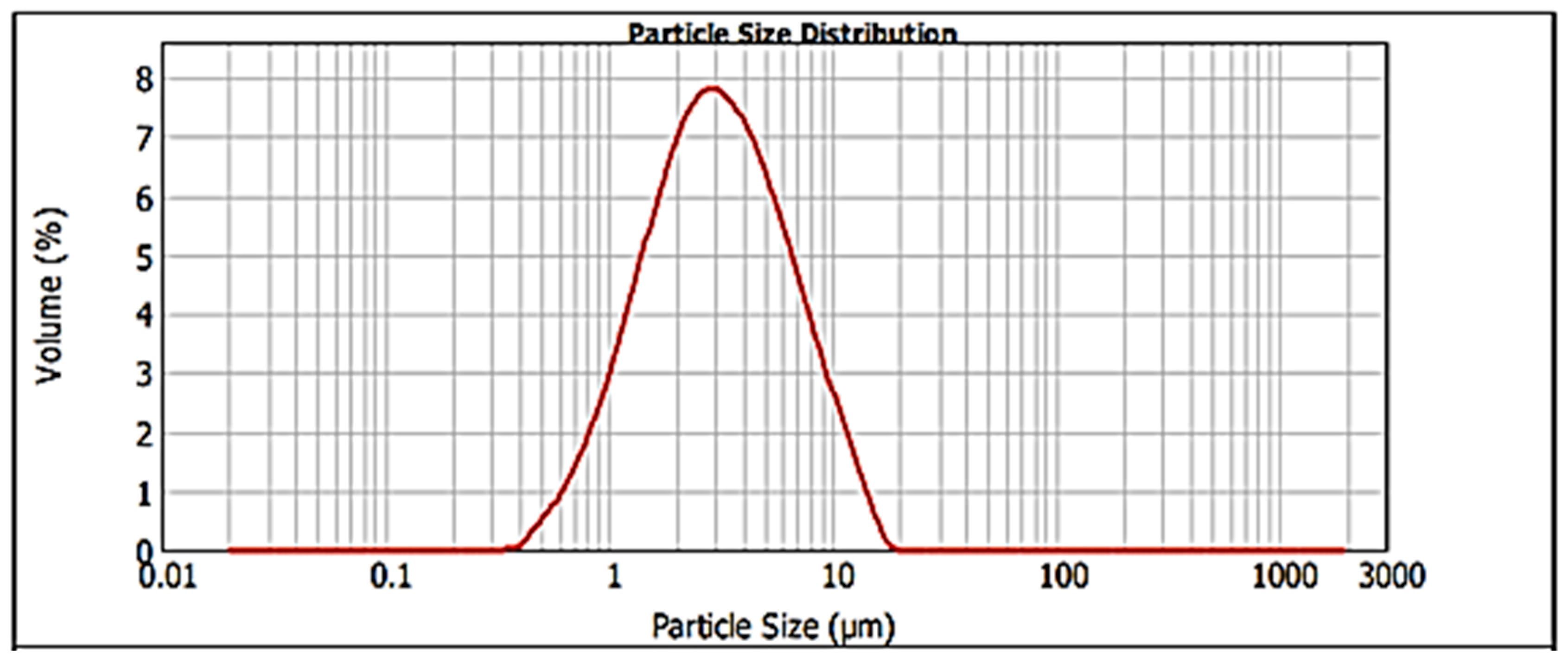
MicroPolish Alumina Powder-Deagglomerated Alpha (1 µm) (Microdiamant USA, Inc., Smithfield, PA, USA), was used as abrasive. To confirm the abrasive particles’ size and distribution, an analysis was performed using laser diffraction equipment (Malvern 2000 Particle Sizer Analyzer with a Hydro 2000G sample scattering unit). The Alumina abrasive powder was dispersed in water at 250 rpm and three readings were taken. The average granulometry value obtained in this analysis was 2.259 µm. Figure 1 shows the morphological characterization of the geometry of the alumina abrasive particles used in this work.
The mathematical models used in this process were based on the theory of Mie or Fraunhofer to form and generate a granulometric distribution based on Equivalent Spherical Diameter Volume. In Figure 2, it is possible to see the graph of the abrasive particles size distribution.

2.2. Methods

2.2.1. Coating Deposition Process

In the deposition process carried out for this work, a CemeCon® CC800/9 ML reactor was used with four Ti targets. In the deposition process, three gases were employed, Argon, Nitrogen, and Krypton, each with the appropriate proportion (Kr: 260 mln; Ar+: 330 mln; N2: 75 mln). During deposition, the sample holder and the corresponding satellites rotate to ensure the coating homogeneity. Table 2 summarizes the parameters used in PVD deposition.

2.2.2. Morphology and Thickness Analysis of the Coating

For the morphology and thickness analysis of the coating, it was necessary to partially cut the samples at the back side with a disc saw. A deep groove was made to help break up the samples. After the groove, the samples were immersed in liquid nitrogen for 30 min to facilitate breakage, ensuring the absence of stresses or mechanical deformations in both the substrate and the coating close to the broken area.
To evaluate and measure the thickness and characterize the surface morphology, a FEI Quanta 400FEG scanning electron microscope (SEM) equipped with an EDAX Genesis X-ray spectroscope (EDS) was used. Using the SEM equipment, two observation modes were used to capture the images: secondary electrons (SE) and backscattered electrons (BSE).

2.2.3. Roughness Analysis—AFM and 3D Profilometry

Initially, an analysis of the coated sample surface roughness was carried out to study the film deposited on the substrate using a VEECO Multimode atomic force microscope (AFM). The equipment used has a 7 nm beam probe and the software used was the NanoScope 6.13. In this analysis, arithmetic average roughness of the surface (Ra) and maximum surface roughness (Rmax) were considered. After the first approach with the AFM, a 3D evaluation of the craters was performed. In the surface roughness analysis of the craters, a 3D optical profilometer equipment (Sensofar S-neox) and the SensoMap analysis software were used. Nine measurements were performed following the ISO 25178 standard. The visualization of the inside craters texture was performed using a higher magnification (50× interferometric objective, acquisition area of 351 μm × 264 μm) under confocal mode (CO). In this analysis, for the 3D surface characterization, the amplitude parameters of the surface roughness arithmetic mean (Sa), maximum topographic surface height (Sz), and Skewness of topography height distribution (Ssk) were analyzed.

2.2.4. Adhesion Analysis

To evaluate the adhesion of the TiN film to the substrate, two tests were performed: the Rockwell indentation test and the scratch test. The analysis by indentation is based on the evaluation that is made concerning the behavior of the coating through an indentation performed with a conical Rockwell diamond indenter, using a 150 kgf normal load. The equipment used was an EMCO M4U Universal Hardness Tester. Produced craters were observed using an OLYMPUS BX51M optical microscope (OM) at ×100 magnification. In this test, the VDI 3198:1991 standard was followed; the primary goal was to obtain an adhesion classification regarding the appearance of the indentation edge. In the scratch test, the cohesive (Lc1) and adhesive (Lc2) failure modes were obtained, making it possible to quantify the normal load adhesion between the TiN film and the steel substrate. In this test, a Rockwell indenter was used. The indenter slides at a speed of 10 mm/min, with a load range of 0 to 30 N at a load increasing rate of 10 N/min. Six readings were performed per sample: three readings in two orthogonal directions. The scratch tests were developed using a CSM REVETEST scratch tester equipped with an acoustic emission detector, according to BS EN ISO 20502:2016.

2.2.5. XRD Analysis

In the X-ray Diffraction (XRD) analysis, the characterization was focused on the TiN coating. The equipment used was a Rigaku SmartLabSe diffractometer, whose operating characteristics are 40 kV voltage, 30 mA current intensity, Cu Kα Radiation with a wavelength of 1.5406 Å, step size [2θ]: 0.01°, 2 h time, with 1.0 s scan step time; the method used was top of smoothed peak. The spectrum acquisition was conducted in conventional mode.

2.2.6. Nano-Hardness Assessment

In the hardness analysis of the studied film, the Nanoindenter CSM equipped with a Berkovich diamond indenter with used with the application of the Oliver and Pharr method [33,34]. The NHTX S/N 01-02934 equipment operating settings were: 150 mN maximum load, 10 Hz acquisition rate, 1 s dwell time, 200 mN/min charge rate, and 200 mN/min discharge rate.

2.2.7. Micro-Abrasion Test

Micro-scale abrasion tests were performed using a PLINT TE-66 micro-abrasion device. During the abrasion process, three concentrations of abrasive slurry were used, using 3 µm abrasive Alumina particles. The tests were conducted with three different test durations (500, 1000, and 1500 cycles). For each slurry concentration, 25, 35, and 45 g were used for each 100 mL of distilled water. The ball rotation speed was 80 rpm (0.106 m/s) and the load used was 2 N. Three tests were performed for each of the combinations, as shown in Table 3. AISI 52100 steel balls used in these tests were etched by 4% Nital for 60 s.
For the calculations of the volume removed from craters, the following expression was used:
V = π d 4 64 · r
where d represents the crater diameter in mm and r represents the radius of the ball used in the test in mm. The wear rate was calculated using the following Archard’s expression:
K = V s · F
where K represents the specific wear rate [mm3/Nm], V corresponds to the volume of material removed [mm3], s embodies the sliding distance [m], and F relates to the Normal Load [N] [35].

3. Results and Discussion

3.1. Coatings Morphology and Thickness

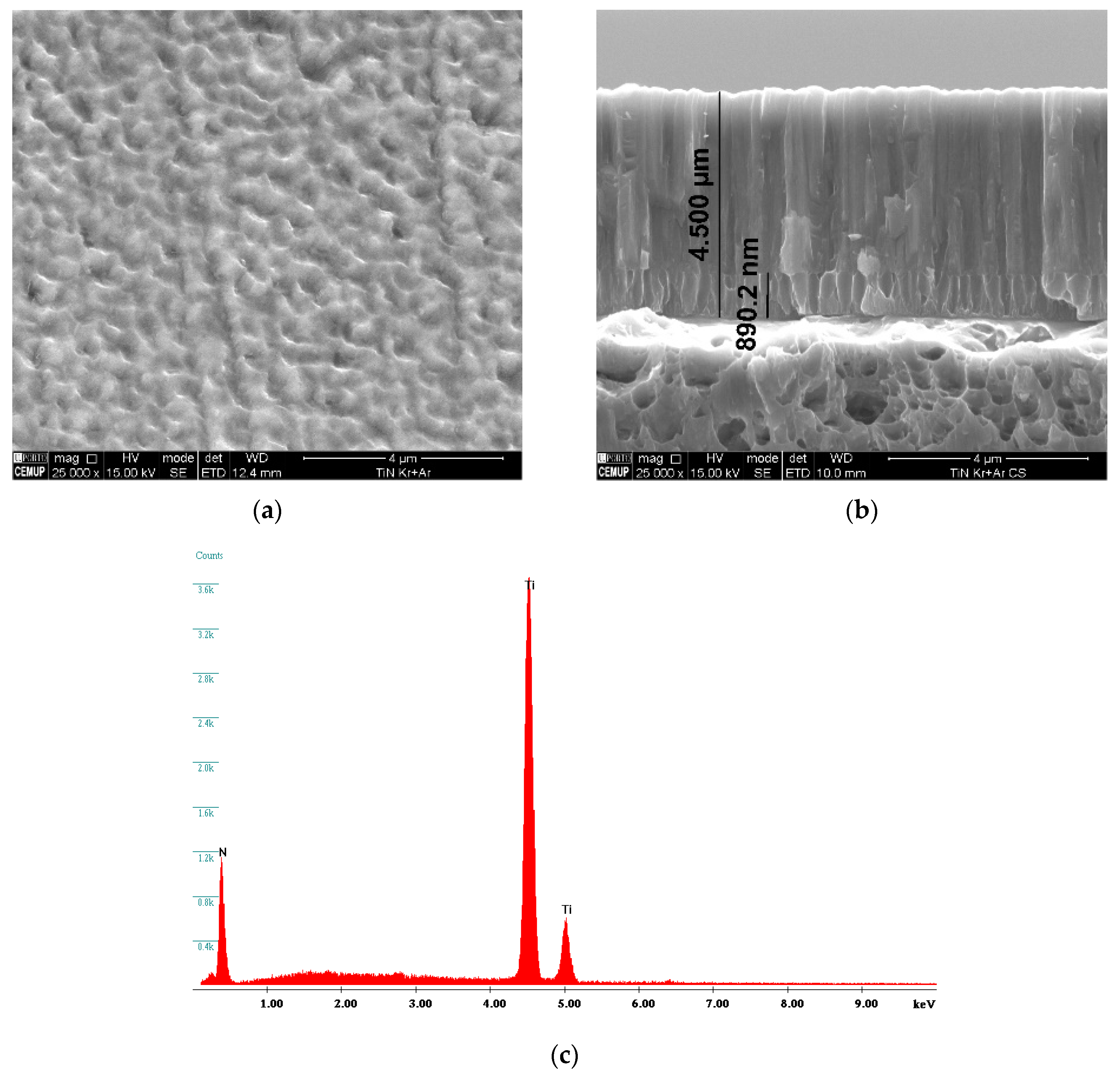
TiN coating displays a homogeneous surface morphology, as can be seen in Figure 3a. The cross-section morphology shows as a columnar-type structure, where the columns grow from the substrate up to the topmost surface. Three different zones can be perceived in the cross section: the substrate layer, the adhesion layer, and the final film. The different zones observed in the cross-section morphology of the film are the result of the use of different biases applied to the substrate. At the beginning of the deposition, the bias applied at the substrate was −105 V to ensure good adhesion to the substrate; in the following layer, the bias used was −90 V. It is also possible to verify that the coating is 4.5 μm thick. As expected, taking into account the deposition conditions, the EDS spectrum acquired in the film confirms the presence of Ti and N; this considers the elements stoichiometry, i.e., at.% of each elements ~50 at.%, corresponds to TiN.

3.2. Roughness Results

The evaluation of the coating surface roughness was performed by AFM, as presented in Figure 4.
Observing Figure 4, it is possible to state that the coated surface is smooth and homogeneous. The data obtained and recorded revealed that the arithmetic mean surface roughness was 0.0267 µm (Ra = 0.0267 ± 0.002 µm) and maximum roughness was 0.335 µm (Rmax = 0.335 ± 0.007 µm). The values obtained are in the range of the values reported for TiN films in the literature [21,36].
After performing the microabrasion tests, a 3D evaluation of the inner (central) part of the craters was conducted, following the procedures described in the Experimental section. The corresponding results can be seen in Table 4.
Figure 5 shows the 3D topography of the analyzed craters. From the table, it is possible to observe that, when retaining the number of cycles and increasing the concentration of the abrasive slurry, the particles create grooves that cause a more pronounced passage of the abrasive, leading to more pronounced grooves. Maintaining the same concentration of abrasive and increasing the number of cycles, the roughness increases. This phenomenon agrees with the literature, which states that rolling wear is a more effective mechanism for material removal than groove wear [31]. Comparing the images in Figure 5a–c, there is an increase in the wear surface of the ball as the slurry concentration increases, from 25 g/100 mL to 45 g/100 mL. This phenomenon is repeated for a greater number of cycles (1500 cycles), as can be seen in Figure 5d–f. Figure 5c,f show that the groove created in the specimens surface is wider, deviating from the center and creating more pronounced grooves around the center. This phenomenon is associated with the high concentration of alumina. The concentrations of 25 or 35 g/100 mL are those that presented more homogeneous groove trace.

3.3. Adhesion Evaluation

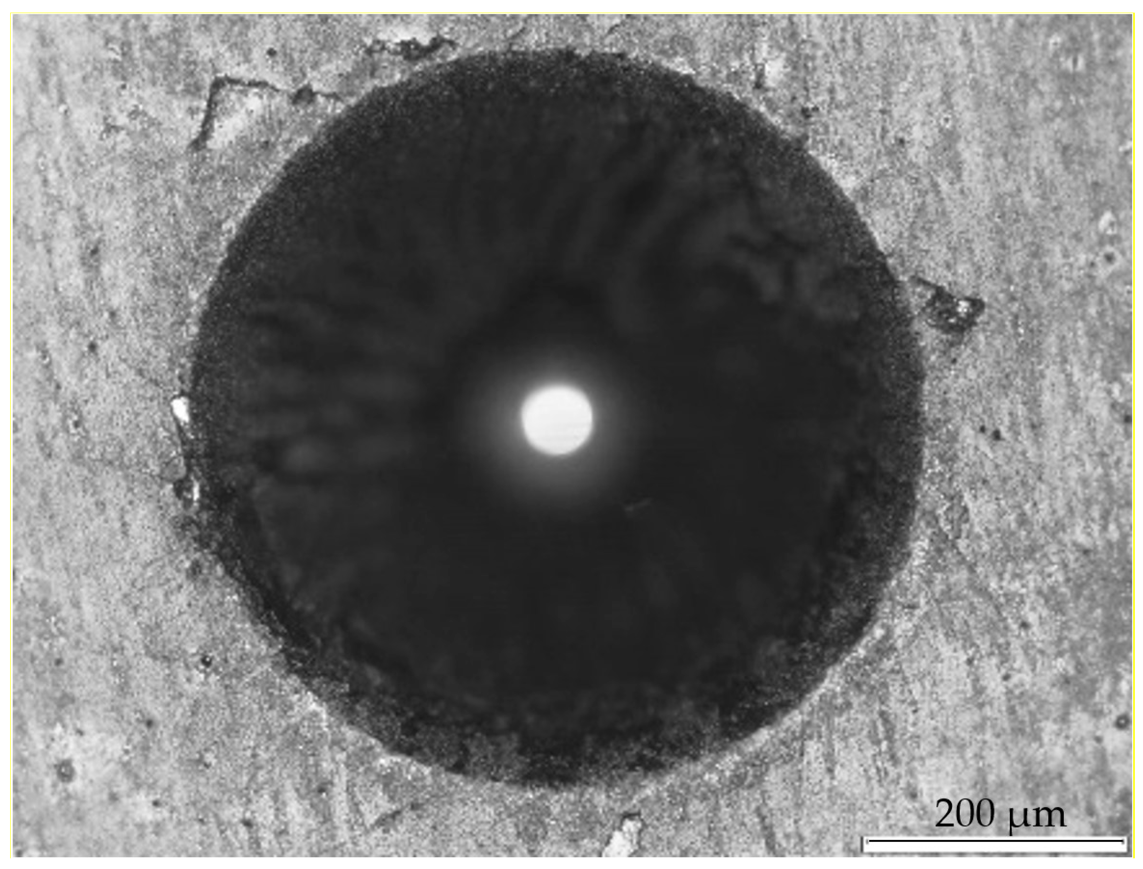
Figure 6 shows an image of the Rockwell-C adhesion test conducted at the film under a normal load of 15 N. According to the standard, the cracks identified at the indentation edge can be classified as HF1, considered acceptable as described in the standard, as well as in line with the conclusion of the authors’ work in [25].
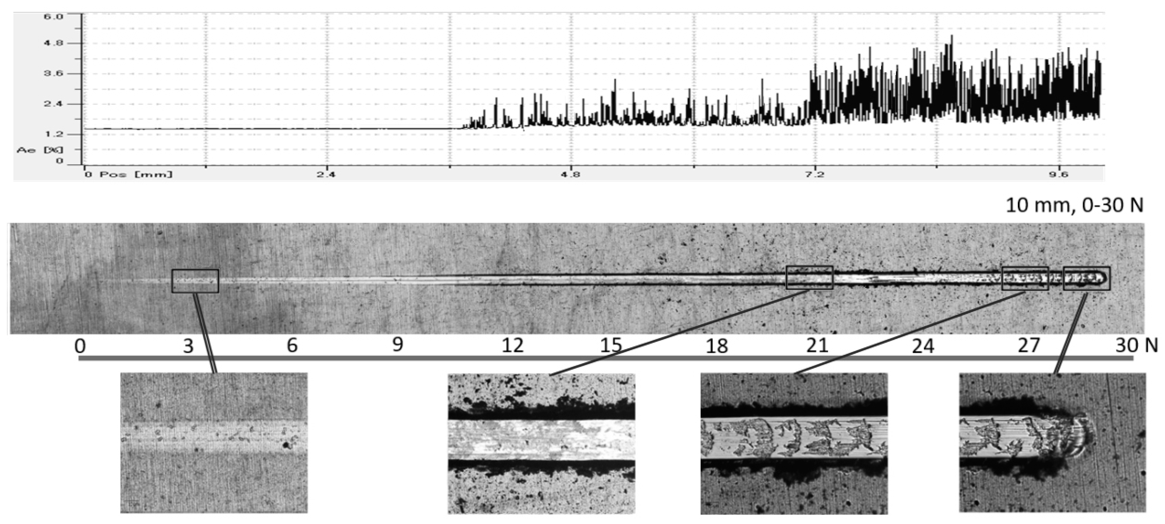
Regarding the scratch test, it was possible to observe that the first acoustic emission signal only appears under a normal load of approximately 10.5 N, as can be seen in Figure 7. Thus, it can be determined that the first cohesive failure event (lateral delamination) appears under this load. This failure agrees with other works [29,30]. Observing Figure 7, when the load is approximately 21 N, it is possible to verify that the first event of adhesive failure (lateral peeling) appears and small portions of chips on the track and exposure of the substrate occur. In this phase, the acoustic emission increases in amplitude and frequency. This adhesive failure occurs earlier when compared with other work performed by Silva et al. [27]. Taking into account the adhesion values and the critical load values globally, the film is well adhered to the substrate, ensuring that it will not pull off during micro-scale abrasion experiments.

3.4. Coating’s Structure

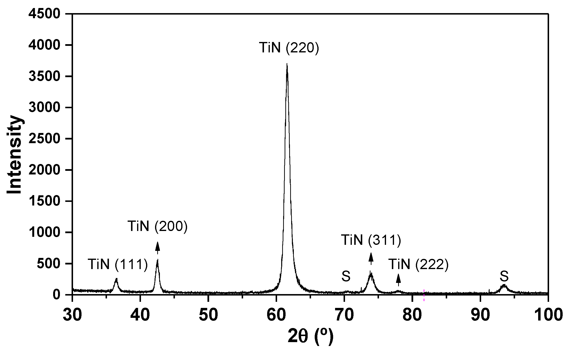
Figure 8 shows the XRD diffraction pattern of the produced film. As expected, the diffraction peaks can be assigned to the crystalline TiN phase with an fcc structure. The strong diffraction peak at 62° indicates the film growth with a strong (220) preferential orientation. Diffraction peaks from the substrate can also be detected.

3.5. Nano-Hardness

In this work, an analysis of the TiN coating hardness was also conducted. Due to the low thickness of the coating, it was necessary to perform several indentations with very light loads and high accuracy to reduce the uncertainty in this test. With the small loads applied during the hardness test (Figure 9), the influence of the substrate on the measurements was prevented. From these tests, the following properties have been evaluated: (a) Young’s modulus 357.56 ± 19.87 GPa and (b) hardness 29.53 ± 1.34 GPa. These values are 15% lower than those mentioned by [37]; however, the values exceed those mentioned by [16] by approximately 5%.
Observing the “load-unload” curves seen in Figure 9, it is possible to verify that the deepness reached in the hardness test was just a little higher than 10% of the coating thickness, showing that there was practically no influence of the substrate in the test. In fact, looking at Figure 9, the slopes of the curves are very similar, meaning that the substrate had no influence on the presented hardness value.

3.6. Micro-Abrasion Analysis

The micro-scale abrasion results for the different test conditions are shown in Figure 10. For a better interpretation, Table 5 summarizes the volume loss, size of the craters produced, and specific wear rate as a function of the test conditions, i.e., abrasive slurry and sliding distance.
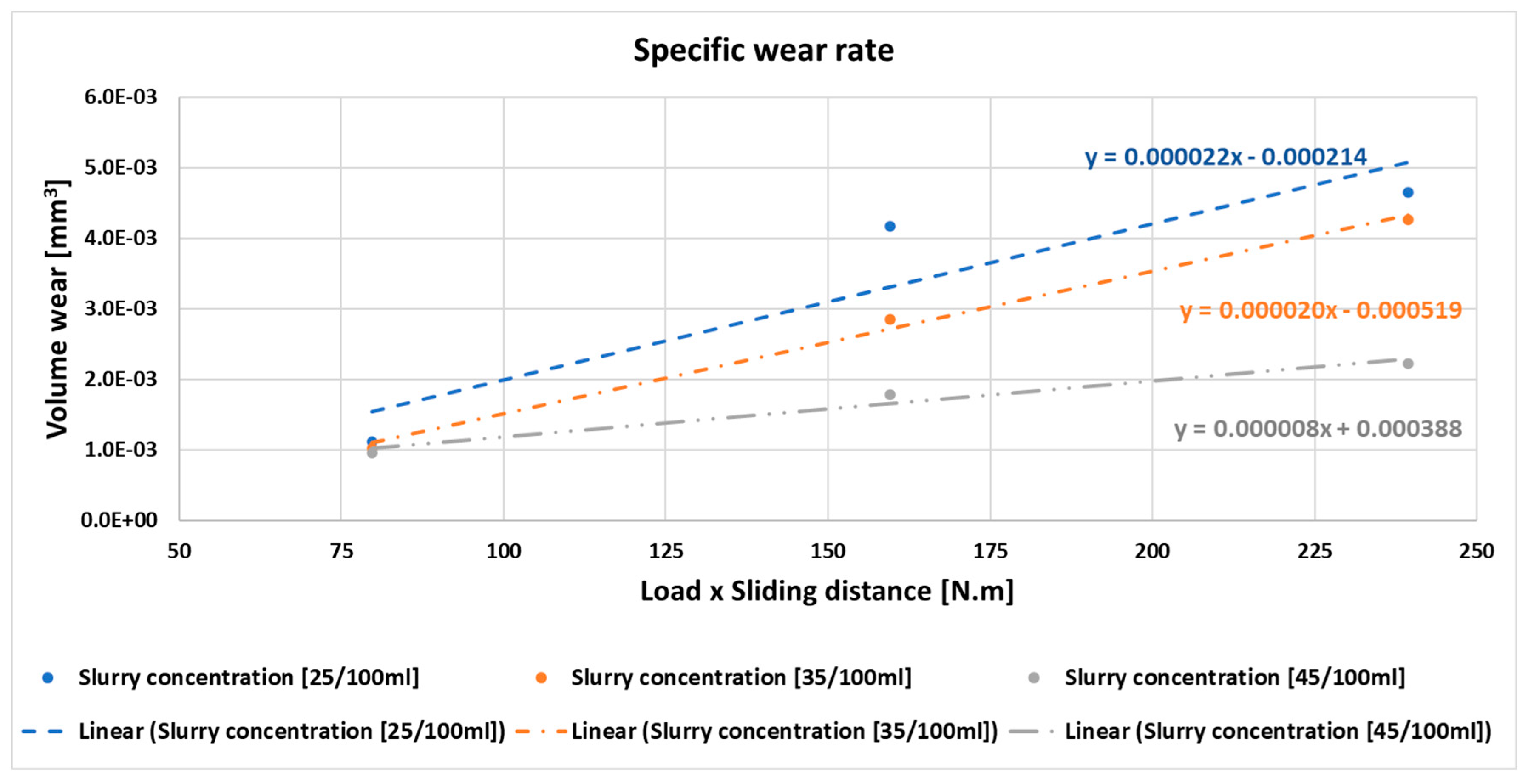
In Figure 11, it can be seen that the specific wear rate of the coating decreases with the increase of the abrasive slurry concentration. Additionally, in Table 5, it can be seen that: (i) for the same abrasive concentration, the volume loss of the film increases with the increasing of the sliding distance, and (ii) the dimension of the produced scars on the surface of the film decreases with increasing slurry concentration, which consequently decreases the volume loss (see Figure S1 in Supplementary Material).
To understand the changes in the specific wear rate and volume loss of the film as a function of the sliding distance and abrasive concentration used, the wear mechanisms presented in the scars were investigated. Figure S2 (in Supplementary Material) shows the aspect of the wear craters caused by the movement of an AISI 52100 ball as a function of the abrasive concentration and increasing sliding distance. As can be seen, scars produced under the low abrasive concentration and with increasing sliding distance displayed a mix wear mechanism (rolling and grooving). As expected, the increase of the sliding distance increased the size of the scars. An increase of the size of the scars was also observed for the other abrasive slurry concentrations with increasing sliding distance. Nevertheless, the wear mechanism has changed. Indeed, the increase of the slurry concentration from 25 to 35 g/100 mL changes the wear mechanism from a mixed rolling/grooving mode to pure grooving. Further increase of the abrasive slurry concentration to 45 g/100 mL produces a more severe grooving wear mechanism. This tendency corroborates the increase of roughness of the scar as presented in Table 4 and Figure 5.
This change of wear mechanism with the increase in abrasive slurry concentration does not follow the tendency reported in others studies, where it has been reported that increasing the abrasive slurry concentration promotes the formation of rolling wear [31]. As explained below, the different trend is caused by the roughness of the ball surface, as observed by Batista et al. [17]. During abrasion experiments at the lowest slurry concentration, the slurry in the contact in one direction rolls at the film surface producing rolling wear; in the other direction, due to the roughness of the ball, the slurry will agglomerate at the ball grooves and, due to the ball movement, will produce grooving wear. A mixed mode wear mechanism in the scar is thus established. When the abrasive concentration is increased, there is more abrasive available to agglomerate at the ball valleys which, due to the movement of the ball, will scratch the surface, producing a severe grooving wear mechanism. The higher the abrasive slurry concentration, the more defined grooving wear will be, as can be seen in Figure 11. In all the scars in the exit zone of the abrasive slurry, the presence of agglomerated material is visible. According to the EDS (see Figure S2 in Supplementary Material), the adhered material corresponds to abrasive particles of alumina that have stacked on that zone due to the movement of the ball and the shape of the crater. The decrease of the specific wear rate of the TiN film with increasing abrasive slurry concentration can be interpreted based on the changes of wear mechanisms. Indeed, it is well known from the literature that rolling wear is a more effective mechanism in removing material than grooving wear [31]. Thus, a change from a mixed wear mechanism to grooving wear, as observed with increasing abrasive slurry concentration, explains the decrease of specific wear rate.

3.7. SEM Balls Analysis

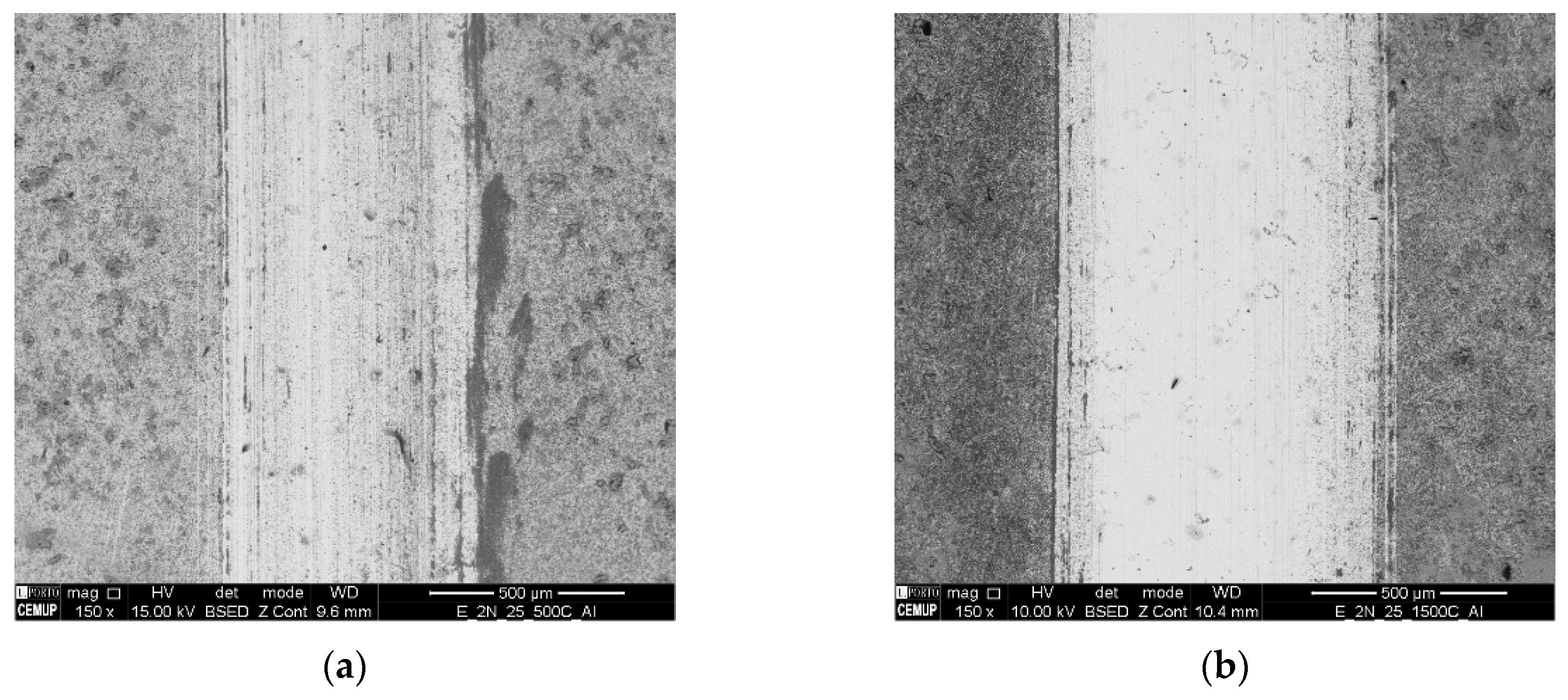
Some researchers have studied the importance of ball etching level in wear mechanisms. In this sense, and following these studies, an aggregation of the alumina particles in the alveoli created by the 4% Nital etching procedure was expected [16,17]. Observing the tracks on the balls after the tests (Figure 12a,b), it was found that, for 2 N load, as the number of cycles increase, the topography of the track became smoother, making it difficult to locate alumina particles. Considering these results, it was noticeable that the load used versus the cycles number were excessive.
Thus, in future works, it is desirable to reduce the load so that the alumina particles are aggregated to the texture created in the sphere in order to have a more abrasive effect.

4. Concluding Remarks

In this work, the effect of different test durations and abrasive particle concentrations of 3 μm Al2O3 on TiN PVD thin coating were studied. The rotation speed used in the test was 80 rpm, the normal load used was 2 N, and three different test durations were used (39.9 m, 79.8 m, and 119.7 m sliding distance). Three concentrations of abrasive particles of 3 μm Al2O3 in distilled water were used: 25 g/100 mL, 35 g/100 mL, and 45 g/100 mL. AISI 52100 steel balls were used with texture and roughness induced by a chemical etching procedure using 4% Nital for 60 s. Craters obtained during micro-abrasion tests were carefully analyzed using SEM and 3D topography to evaluate wear modes and their transition as a function of applied normal load, sliding distance, and abrasive particles concentration. The tracks induced by the wear tests on the textured balls surface were also observed using SEM to assess a possible embedding process of these abrasive particles on the tracks and to verify the influence on the wear modes. Based on the observations made, it was possible to conclude the following:
-
Increasing the abrasive concentration reduced the specific wear rate of the film as it promoted a grooving wear mechanism; this mechanism is less effective in removing material when compared to the mix rolling/grooving mode detected in the condition tested with lower abrasive concentration.
-
The roughness of the ball (due to the chemical attack) combined with the increase in the abrasive concentration promoted the formation of a grooving wear mechanism; this is because there are more particles available and more aggregation of particles in the ball which scratch the specimen surface.
-
The test duration promoted more defined craters; this is because the grooving wear mode increased, as well as due to a greater wear volume.
-
Contrary to what is reported in the literature, which suggests that increasing the abrasive concentration of particles preferentially promotes rolling, when balls with induced roughness were used, grooving was preferentially promoted.

Supplementary Materials

The following supporting information can be downloaded at: https://www.mdpi.com/article/10.3390/coatings13030628/s1, Figure S1: (a) Craters mean diameter and (b) volume loss of material, regarding slurry concentration for the different sliding distances, Figure S2: Wear crater detail (a) at 500× magnification; (b) at 3500× magnification; with the following EDS analyses: (c) Z1—Substrate; (d) Z2—Abrasive Alumina; and (e) Z3—TiN.

Author Contributions

G.F.P.: writing original draft, Investigation; F.J.G.S.: Conceptualization, Supervision, Writing—review and editing; A.B.: Investigation, Writing—review and editing; F.F.: Supervision, Review and editing; M.E.: Software; V.F.C.S.: Investigation, Formal analysis. All authors have read and agreed to the published version of the manuscript.

Funding

Filipe Fernandes acknowledges the MCTool21—ref. “POCI-01-0247-FEDER-045940” and CEMMPRE—ref. “UIDB/00285/2020” projects, sponsored by FEDER funds through the program COMPETE—Programa Operacional Factores de Competitividade—and by national funds through FCT—Fundação para a Ciência e a Tecnologia.

Institutional Review Board Statement

Not applicable.

Informed Consent Statement

Not applicable.

Data Availability Statement

Not applicable.

Acknowledgments

Authors would like to thanks to Rui Rocha from CEMUP (Porto, Portugal), due to his active collaboration in getting the best SEM pictures, helping with his critical analysis of some phenomena. Authors also would like to thank Ing. Ricardo Alexandre due to is extremely important role in providing all the coatings through TEandM company. Filipe Oliveira is acknowledged due to its support in 3D microscope analyses. Jorge Seabra and Carlos Fernandes are also acknowledged due to his support, as well as LAETA/INEGI/CETRIB due to the financial support provided in this work, and in many others.

Conflicts of Interest

Authors declare that they have no known competing financial interest or personal relationships that could have appeared to influence the work reported in this paper.

References

  1. Martinho, R.P.; Silva, F.J.G.; Martins, C.; Lopes, H. Comparative study of PVD and CVD cutting tools performance in milling of duplex stainless steel. Int. J. Adv. Manuf. Technol. 2019, 102, 2423–2439. [Google Scholar] [CrossRef]
  2. Sousa, V.F.; Silva, F.; Alexandre, R.; Fecheira, J. Study of the wear behaviour of TiAlSiN and TiAlN PVD coated tools on milling operations of pre-hardened tool steel. Wear 2021, 476, 203695. [Google Scholar] [CrossRef]
  3. Silva, F.; Martinho, R.; Andrade, M.; Baptista, A.; Alexandre, R. Improving the Wear Resistance of Moulds for the Injection of Glass Fibre–Reinforced Plastics Using PVD Coatings: A Comparative Study. Coatings 2017, 7, 28. [Google Scholar] [CrossRef] [Green Version]
  4. Rutherford, K.; Hutchings, I. A micro-abrasive wear test, with particular application to coated systems. Surf. Coat. Technol. 1996, 79, 231–239. [Google Scholar] [CrossRef]
  5. Petersen; Link, R.; Rutherford, K.; Hutchings, I. Theory and Application of a Micro-Scale Abrasive Wear Test. J. Test. Eval. 1997, 25, 250. [Google Scholar] [CrossRef]
  6. Baptista, A.; Pinto, G.; Silva, F.; Ferreira, A.; Pinto, A.; Sousa, V. Wear Characterization of Chromium PVD Coatings on Polymeric Substrate for Automotive Optical Components. Coatings 2021, 11, 555. [Google Scholar] [CrossRef]
  7. Buchanan, F.; Shipway, P. Microabrasion—A simple method to assess surface degradation of UHMWPE following sterilisation and ageing. Biomaterials 2002, 23, 93–100. [Google Scholar] [CrossRef]
  8. Gee, M.; Gant, A.; Hutchings, I.; Bethke, R.; Schiffman, K.; Van Acker, K.; Poulat, S.; Gachon, Y.; von Stebut, J. Progress towards standardisation of ball cratering. Wear 2003, 255, 1–13. [Google Scholar] [CrossRef]
  9. Gee, M.; Gant, A.; Hutchings, I.; Kusano, Y.; Schiffman, K.; Van Acker, K.; Poulat, S.; Gachon, Y.; von Stebut, J.; Hatto, P.; et al. Results from an interlaboratory exercise to validate the micro-scale abrasion test. Wear 2005, 259, 27–35. [Google Scholar] [CrossRef]
  10. Schiffmann, K.; Bethke, R.; Kristen, N. Analysis of perforating and non-perforating micro-scale abrasion tests on coated substrates. Surf. Coat. Technol. 2005, 200, 2348–2357. [Google Scholar] [CrossRef]
  11. Kusano, Y.; Van Acker, K.; Hutchings, I. Methods of data analysis for the micro-scale abrasion test on coated substrates. Surf. Coat. Technol. 2004, 183, 312–327. [Google Scholar] [CrossRef]
  12. Cozza, R.C. Influence of the normal force, abrasive slurry concentration and abrasive wear modes on the coefficient of friction in ball-cratering wear tests. Tribol. Int. 2014, 70, 52–62. [Google Scholar] [CrossRef]
  13. Batista, J.; Joseph, M.; Godoy, C.; Matthews, A. Micro-abrasion wear testing of PVD TiN coatings on untreated and plasma nitrided AISI H13 steel. Wear 2002, 249, 971–979. [Google Scholar] [CrossRef]
  14. Silva, F.J.G.; Casais, R.B.; Martinho, R.P.; Baptista, A.P.M. Role of abrasive material on micro-abrasion wear tests. Wear 2011, 271, 2632–2639. [Google Scholar] [CrossRef] [Green Version]
  15. Ardila, M.; Costa, H.; de Mello, J. Influence of the ball material on friction and wear in microabrasion tests. Wear 2020, 450-451, 203266. [Google Scholar] [CrossRef]
  16. Pinto, G.; Baptista, A.; Silva, F.; Porteiro, J.; Míguez, J.; Alexandre, R. Study on the Influence of the Ball Material on Abrasive Particles’ Dynamics in Ball-Cratering Thin Coatings Wear Tests. Materials 2021, 14, 668. [Google Scholar] [CrossRef]
  17. Baptista, A.; Silva, F.; Pinto, G.; Porteiro, J.; Míguez, J.; Alexandre, R.; Sousa, V. Influence of the ball surface texture in the dragging of abrasive particles on micro-abrasion wear tests. Wear 2021, 476, 203730. [Google Scholar] [CrossRef]
  18. Ardila, M.; Costa, H.; de Mello, J. Topographic evolution of balls used in microabrasion tests. Wear 2021, 476, 203582. [Google Scholar] [CrossRef]
  19. Esteves, P.; de Macêdo, M.; Souza, R.; Scandian, C. Effect of ball rotation speed on wear coefficient and particle behavior in micro-abrasive wear tests. Wear 2019, 426–427, 137–141. [Google Scholar] [CrossRef]
  20. Stack, M.; Mathew, M. Mapping the micro-abrasion resistance of WC/Co based coatings in aqueous conditions. Surf. Coat. Technol. 2004, 183, 337–346. [Google Scholar] [CrossRef]
  21. Silva, F.J.G.; Fernandes, A.J.S.; Costa, F.M.; Teixeira, V.; Baptista, A.P.M.; Pereira, E. Tribological behaviour of CVD diamond films on steel substrates. Wear 2003, 255, 846–853. [Google Scholar] [CrossRef]
  22. Silva, F.G.; Neto, M.A.; Fernandes AJ, S.; Costa, F.M.; Oliveira, F.J.; Silva, R.F. Adhesion and Wear B haviour of NCD Coatings on Si3N4 by Micro-Abrasion Tests. J. Nanosci. Nanotechnol. 2009, 9, 3938–3943. [Google Scholar] [CrossRef] [PubMed] [Green Version]
  23. Rodríguez-Castro, G.; Reséndiz-Calderon, C.; Jiménez-Tinoco, L.; Meneses-Amador, A.; Gallardo-Hernández, E.; Campos-Silva, I. Micro-abrasive wear resistance of CoB/Co2B coatings formed in CoCrMo alloy. Surf. Coat. Technol. 2015, 284, 258–263. [Google Scholar] [CrossRef]
  24. Cozza, R.C. A study on friction coefficient and wear coefficient of coated systems submitted to micro-scale abrasion tests. Surf. Coat. Technol. 2013, 215, 224–233. [Google Scholar] [CrossRef] [Green Version]
  25. Silva, F.J.G.; Martinho, R.P.; Alexandre, R.J.D.; Baptista, A.P.M. Wear Resistance of TiAlSiN Thin Coatings. J. Nanosci. Nanotechnol. 2012, 12, 9094–9101. [Google Scholar] [CrossRef]
  26. Martinho, R.; Andrade, M.; Silva, F.; Alexandre, R.; Baptista, A. Micro-abrasion wear behaviour of TiAlCrSiN nanostructured coatings. Wear 2009, 267, 1160–1165. [Google Scholar] [CrossRef] [Green Version]
  27. Silva, F.J.G.; Martinho, R.P.; Baptista, A.P.M. Characterization of laboratory and industrial CrN/CrCN/diamond-like carbon coatings. Thin Solid Films 2014, 550, 278–284. [Google Scholar] [CrossRef]
  28. Stachowiak, G.; Celliers, O. Ball-cratering abrasion tests of high-Cr white cast irons. Tribol. Int. 2005, 38, 1076–1087. [Google Scholar] [CrossRef]
  29. Moreira, A.B.V. Cast ferrous Alloys Reinforced with Structural Ceramics for Wear Resistance Applications. Ph.D. Thesis, Department of Metallurgical and Materials Engineering, Faculty of Engineering, University of Porto, Porto, Portugal, 2022. [Google Scholar]
  30. Bello, J.; Wood, R. Micro-abrasion of filled and unfilled polyamide 11 coatings. Wear 2005, 258, 294–302. [Google Scholar] [CrossRef]
  31. Fernandes, F.; Ramalho, A.; Loureiro, A.; Cavaleiro, A. Mapping the micro-abrasion resistance of a Ni-based coating deposited by PTA on gray cast iron. Wear 2012, 292–293, 151–158. [Google Scholar] [CrossRef]
  32. Wolfe, G.J. The role of hard coatings in carbide milling tools. J. Vac. Sci. Technol. A Vac. Surf. Film. 1986, 4, 2747–2754. [Google Scholar] [CrossRef]
  33. Oliver, W.C.; Pharr, G.M. An improved technique for determining hardness and elastic modulus using load and displacement sensing indentation experiments. J. Mater. Res. 1992, 7, 1564–1583. [Google Scholar] [CrossRef]
  34. Oliver, W.C.; Pharr, G.M. Measurement of hardness and elastic modulus by instrumented indentation: Advances in understanding and refinements to methodology. J. Mater. Res. 2004, 19, 3–20. [Google Scholar] [CrossRef]
  35. Miranda, J.C.; Ramalho, A.; Cavadas, S. Efeito da temperatura de revenido no comportamento tribologico do aço din 100Cr6. Cienc. Tecnol. Mater. 2006, 18, 35–42. [Google Scholar]
  36. Cozza, R.C.; Tanaka, D.K.; Souza, R.M. Friction coefficient and abrasive wear modes in ball-cratering tests conducted at constant normal force and constant pressure—Preliminary results. Wear 2009, 267, 61–70. [Google Scholar] [CrossRef]
  37. Kumar, S.; Maity, S.R.; Patnaik, L. Effect of heat treatment and TiN coating on AISI O1 cold work tool steel. Mater. Today Proc. 2020, 26, 685–688. [Google Scholar] [CrossRef]
Figure 1. Morphological characterization of the abrasive particles: Alumina Powder-Deagglomerated Alpha 3 µm.
Coatings 13 00628 g001
Figure 2. Alumina powder particles size distribution.
Coatings 13 00628 g002
Figure 3. Morphological characterization of the film: (a) surface, (b) cross-section, (c) EDS spectra.
Coatings 13 00628 g003
Figure 4. Topography AFM analysis of the coating.
Coatings 13 00628 g004
Figure 5. 3D topography of the analyzed craters. 500 cycles with: (a) Slurry concentration 25 g/100 mL, (b) Slurry concentration 35 g/100 mL, (c) Slurry concentration 45 g/100 mL, and 1500 cycles with: (d) Slurry concentration 25 g/100 mL, (e) Slurry concentration 35 g/100 mL, (f) Slurry concentration 45 g/100 mL.
Coatings 13 00628 g005
Figure 6. Rockwell-C indentation performed at the TiN film observed in optical microscope. Absence of severe cracks in the border are visible.
Coatings 13 00628 g006
Figure 7. Scratch track observed in the surface of the film after scratch testing experiment from 0 to 30 N.
Coatings 13 00628 g007
Figure 8. X-ray diffraction pattern of TiN coating.
Coatings 13 00628 g008
Figure 9. Typical load-unload curves, resulting from several nano-hardness tests.
Coatings 13 00628 g009
Figure 10. Wear craters generated by the test ball AISI 52100 and Alumina abrasive particles with a 2 N normal load. (a) SC 25 g/100 mL and 500 cycles; (b) SC 35 g/100 mL and 500 cycles; (c) SC 45 g/100 mL and 500 cycles; (d) SC 25 g/100 mL and 1000 cycles; (e) SC 35 g/100 mL and 1000 cycles; (f) SC 45 g/100 mL and 1000 cycles; (g) SC 25 g/100 mL and 1500 cycles; (h) SC 35 g/100 mL and 1500 cycles; (i) SC 45 g/100 mL and 1500 cycles.
Coatings 13 00628 g010
Figure 11. Specific wear rate regarding abrasive particles concentration for different number of cycles and 2 N normal load.
Coatings 13 00628 g011
Figure 12. SEM track analysis for abrasive alumina powder, (a) SC-25 g/100 mL, 500 cycles; (b) SC-25 g/100 mL, 1500 cycles.
Coatings 13 00628 g012
Table 1. Chemical composition of CALMAX * steel (weight %).
CSiMnCrMoV
0.60.350.84.50.50.2
* Uddeholm CALMAX substrate is a chromium-molybdenum-vanadium alloyed steel.
Table 2. PVD deposition process parameters of the TiN film.
Deposition ParametersValues
Temperature [K]750
Gas pressure [Pa]0.650
Bias range [V]−105 to −90
Rotation speed of the holder [rpm]1
Target current [A]10
Deposition time [min]120
Table 3. Microabrasion Tests (three craters per test).
Tests NumberConcentration [g/100 mL]Cycles [Rotation]Sliding Distance [m]
12550039.9
2100079.8
31500119.7
43550039.9
5100079.8
61500119.7
74550039.9
8100079.8
91500119.7
Table 4. Data collected in the analysis of craters by 3D profilometry.
Tests NumberConcentration
[g/100 mL]
Number of CyclesSa 50× [μm]Sz 50× [μm]
1255000.35442.0810
22510000.31582.2539
32515000.28921.9645
4355000.42593.1506
53510000.28341.7717
63515000.49493.5059
7455000.35462.0869
84510000.29495.7062
94515000.39822.4335
Table 5. Specific wear rate obtained for the TiN films as a function of the abrasive slurry concentration and sliding distance under a normal load of 2 N.
Abrasive Particles Concentration [g/100 mL]CyclesCrater Average Diameter [mm] ± σS–Sliding Distance [m]V–Volume Loss [mm3] ± σK–Specific Wear Rate [mm3/Nm] ± σ
255007.33 × 10−1 ± 8.1 × 10−439.901.12 × 10−3 ± 9.1 × 10−52.2 × 10−5 ± 2.4 × 10⁻⁶
10001.019 ± 1.0 × 10−379.804.17 × 10−3 ± 1.1 × 10⁻⁴
15001.047 ± 1.0× 10−3119.694.64 × 10−3 ± 1.9 × 10⁻⁴
355007.19 × 10−1 ± 8.0 × 10−439.901.03 × 10−3 ± 6.2 × 10−52.0 × 10−5 ± 2.9 × 10⁻⁶
10009.27 × 10−1 ± 1.1 × 10−379.802.85 × 10−3 ± 9.4 × 10⁻⁵
15001.025 ± 7.6 × 10−4119.694.27 × 10−3 ± 5.8 × 10⁻⁵
455007.06 × 10−1 ± 1.2 × 10−339.909.60 × 10−4 ± 9.8 × 10−58.0 × 10−6 ± 1.2 × 10⁻⁷
10008.25 × 10−1 ± 1.1 × 10−379.801.79× 10−3 ± 1.1 × 10⁻⁴
15008.72 × 10−1 ± 8.7× 10−4119.692.23× 10−3 ± 1.1 × 10⁻⁴
Disclaimer/Publisher’s Note: The statements, opinions and data contained in all publications are solely those of the individual author(s) and contributor(s) and not of MDPI and/or the editor(s). MDPI and/or the editor(s) disclaim responsibility for any injury to people or property resulting from any ideas, methods, instructions or products referred to in the content.