1. Introduction
By its nature, plasma spraying is a rapid solidification process in which finely powdered material injected into a plasma jet is almost instantly melted and propelled with high velocity, created by a strong magnetohydrodynamic force against a suitable surface. The aim of this process is to produce a well-adhering coating. This technology is highly versatile because any metallic, ceramic, or even polymeric, material possessing a well-defined melting point may be coated onto nearly any thermally stable substrate surface. Although the technology has matured in recent decades, several limitations exist. These include difficulties in controlling coating porosity, maintaining sufficient adhesion to the substrate, preventing the occurrence of strong residual coating stresses, and overcoming geometrical line-of-sight constraints. Many of these limitations are grounded in the nonlinear character of the deposition process. In this contribution, salient issues of plasma spray technology are addressed and discussed.
2. On the Physics of Plasma Spraying
The plasma spraying process may be described as a sequence of connected energy transfer steps that begin with the transfer of electrical energy from an electric D.C. potential field to a suitable gas, thereby forming a plasma by dissociation and ionization. The process continues with the transfer of thermal energy and momentum from the high-velocity plasma jet to the injected powder particles; this causes them to melt and accelerate toward the target surface. The sequence concludes with the transfer of thermal and kinetic energy contained in the impinging molten particles to the substrate.
2.1. Characteristic Plasma Parameters
Plasmas are considered the fourth state of matter [1,2]. They consist of positively charged ions and electrons, as well as neutral gas atoms, and a broad spectrum of photons from the high-energy UV to the visible range. The plasma state contains a wide range of plasma densities, magnetic field strengths, and temperatures that define characteristic microscopic and macroscopic plasma property parameters [3]. These parameters include Langmuir plasma frequency, Debye screening length, Landau length, collision path length, and collision frequency. The positively charged ‘heavy’ ions and the electrons possess characteristic energy levels (‘temperatures’) that establish a Maxwellian energy distribution. For a so-called equilibrium plasma including thermal plasmas used in plasma spraying, the electron temperature is in the order of the heavy ion temperature and can be experimentally determined by a Langmuir probe [4].
2.2. Electron–Gas Interaction
A thermal plasma originates from the ionization of a suitable gas, such as argon or nitrogen, subjected to a strong electric potential field. Moving charges within the plasma induce a magnetic field strength B perpendicular to the direction of the electric field with current density j. Their vector cross product [j × B] is the magnetohydrodynamic Lorentz force, the vector of which is perpendicular to both j and B. Consequently, the inward directed Lorentz force constricts the plasma column by the so-called magnetic or z-pinch. Figure 1A schematically shows this z-pinch configuration, whereby two planar electrodes (2) conduct the axial current j generated by a capacitor battery (4). The magnetic field strength BΘ produces the inward directed Lorentz force Lz that compresses the plasma column (1). Figure 1B shows an advanced plasmatron configuration for atmospheric plasma spraying.
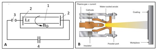
Figure 1.
Design of plasmatron. (A): Schematic representation of a z-pinch apparatus. 1. plasma column, 2. electrodes, 3. arc gap, 4. capacitor battery. (B): Typical plasmatron configuration for atmospheric plasma spraying. © Creative Commons CC BY-NC-ND 4.0.
In addition to the magnetic pinch, a thermal pinch is produced by the reduced conductivity of plasma gas at the water-cooled inner wall (Figure 1B) of the anode nozzle, which, in turn, leads to an increase in current density j at the center of the jet. Then, the charged plasma tends to concentrate along the central axis of the plasmatron, thereby confining the jet. Due to the magnetic and thermal pinch effects, the pressure in the plasma core increases drastically and the plasma jet is blown out of the anode nozzle of the plasmatron with supersonic velocity (Figure 2).
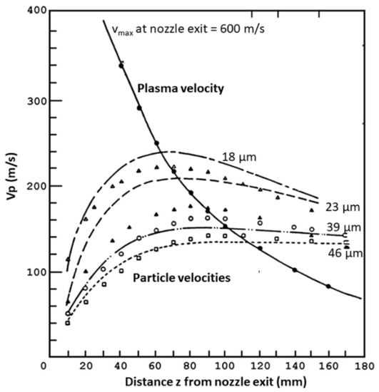
Figure 2.
Transfer of plasma velocity (solid line) to alumina particles of different sizes (18–45 µm; dashed and dotted lines) suspended in an Ar/H2 plasma [5]. © With permission by Wiley-VCH, Weinheim, Germany.
2.3. Plasma–Particle Interaction
A portion of this supersonic velocity will be transferred to the injected powder particles, i.e., the powder particles will gain acceleration from the plasma jet by momentum transfer. In addition, much of the (electric) energy spent on the ionization of the plasma gas will be recovered by recombination of the ionized gas particles in the form of heat. Hence, the hot plasma will heat the powder particles accelerated by momentum transfer along a trajectory in the jet, thus causing them to melt.
Importantly, the degree of momentum transfer depends on the size of the powder particles. A study that involved alumina particles injected into an argon/hydrogen plasma revealed that the supersonic plasma velocity (vmax = 600 m/s) decreases exponentially on exiting from the nozzle of the plasmatron (Figure 2). The injected alumina particles gain momentum slowly as they move along the pressure gradient because of their inertia. In this experiment, small particles of 18 µm diameter reached a maximum velocity of 220 m/s at the target distance of 150 mm, and larger particles with a 46 µm diameter reached a maximum of only 140 m/s. The figure also shows that the velocity attained by small particles decayed faster than that of large particles, due to the higher inertia of the latter [5].
The momentum transfer was modeled using the governing Basset–Boussinesq–Oseen (BBO) equation [6] (Equation (1)), which determines the time dependence of the particle velocity, i.e., the acceleration dVp/dt as a function of the viscous drag force FD and the velocity gradient uR = Vg − Vp as
with the viscous drag coefficient CD = [FD/Ap]/[1/2 · ρg · uR2]. The subscripts g and p refer to gas and particles, respectively, and Ap is the projected surface area of the particle. Solving the BBO equation requires simplifying assumptions such as the strict sphericity of the molten droplets, arrival of particles with constant temperature along the symmetry axis of the plasma jet, dilute, i.e., low-loading plasma conditions, and continuum gas flow. Most strikingly, assumption of diluted conditions is not warranted. This is because the in-flight processing of powder particles to produce plasma-sprayed coatings must be carried out under high loading conditions to make efficient use of the thermal energy that is stored in the plasma. Details on solving the BBO equation can be found in Ref. [7]. They included simplifying assumptions that considered that the actual conditions prevailing during plasma spraying deviated strongly from ideality because generally large temperature gradients were present. As a result, the particle diameter dp and, thus, the projected surface area Ap may change by surface ablation during the flight of the powder particles, and non-continuum effects were expected for particles with dp < 10 µm. To account for these non-ideal conditions, local drag coefficients were defined and introduced based on dimensionless Reynolds numbers [8,9].
dVp/dt = [3CD · ρg/4dp · ρp]׀ug׀ · (ug),
The transfer of heat occurs by three mechanisms: conduction, convection, and radiation. A powder particle injected into the hot plasma jet acquires heat by conduction and convection, but loses heat by radiation. The governing equations are:
Conduction Q = k · Ap · ΔT · t/dp, with k = thermal conductivity, t = time
Convection Q = h · Ap · ΔT, with h = k · Nu/dp
Radiation Q = σ · ε · Ap · ΔT4, with σ = Stefan–Boltzmann coefficient
ε = thermal emissivity
ε = thermal emissivity
Comparing Equation (2a,b) with Equation (2c), it was evident that radiative heat loss of hot particles with high emissivity occurred proportional to the fourth power of the temperature gradient and, thus, became dominant in the process of heat transfer. Hence, it is essential that the particles must be severely overheated to account for radiative heat losses.
The selection of the dimensionless Nusselt Nu number in the thermal convection (Equation (2b)) is crucial for realistically estimating the contribution of convective heat transfer. It is equally as crucial as the choice of the viscous drag coefficient CD for momentum transfer is.
To avoid cumbersome calculations, heat transfer from the plasma to a (spherical) particle was estimated by the empirical Ranz–Marshall expression using the dimensionless Nusselt Nu, Reynolds Re, and Prandtl Pr numbers to read:
with b = 1.0, m = 0.5, and n = 0.33 [10,11]. In this equation, Nu = total heat transfer/heat transfer by conduction; Re = inertia force/viscous force); and Pr = momentum diffusivity/thermal diffusivity.
Nu = 2.0 + b · Rem · Prn,
The (simplified) exact heat transfer equation based on Fourier’s Law can be written as
with k = thermal conductivity, cp = specific heat, h = specific plasma enthalpy, and r = radial coordinate. An exact solution for this equation under low-loading conditions was provided by Chen and Pfender [12], considering heating of particles with and without evaporation.
Q0 = 4π · r2 (k · dh/cpdr),
Proulx et al. [13] attempted to model the heat transfer by using the four plasma conversation equations of mass, momentum, energy, and species [14] coupled to the Maxwell electromagnetic field equations. Details can be obtained from Ref. [7]. Additional information on modeling heat transfer is available in the studies by Fauchais and Vardelle [15], Golosnoy et al. [16], and Mostaghimi and Chandra [17]. Such modeling approaches are predominantly carried out assuming low particle density in the plasma plume. However, this is erroneous, as plasma spraying processes generally involve a high density of particles to become economically viable. In this case, particles interacted, thus causing a decrease in the momentum and temperature of the plasma jet with increasing particle densities. In particular, the decrease in the plasma temperature is related to (i) local cooling of the plasma by heat extracted to melt larger masses of particles, (ii) evaporation of particles altering the thermophysical and transport properties of the plasma, and (iii) forced evaporation of small particles that radiate plasma energy away.
2.4. Particle–Substrate Interaction
Plasma-sprayed coatings are constructed particle by particle, resulting in a chaotic surface structure. The liquid droplets created by melting the powder particles impact the surface to be coated and, given reasonably low viscosity, will splash across the already deposited and frozen splats, the roughness of which largely determines the solidification kinetics as well as the size and morphology of the splats produced by newly arriving particles. It is crucial to consider that a liquid or semi-liquid particle on arrival at the surface will never encounter a permanent liquid melt pool since solidification rates are extremely fast, in the range of 106–107 K/s, orders of magnitude faster than the intermission time of particle arrival, i.e., the time lag between two arriving particles moving on an identical trajectory.
The mechanical properties of the deposited coating layer depend on (i) the velocity and temperature of the particles on impact, (ii) the relative movement of the plasmatron as well as the substrate, and (iii) the cooling of the substrate and the coating during the deposition process. Wetting and flow properties of the molten droplets on impact are influenced by (i) the porosity of the previously deposited coating, (ii) morphology and roughness of the substrate/coating interface, and (iii) cohesion within the coating layer and adhesion of the coating to the substrate.
The liquid droplets, which are almost spherical in shape, arriving with high velocity at the target surface will be flattened on impact. The flattening ratio ξ = Ds/dp (splat diameter/droplet diameter) of a liquid particle impacting at an angle of 90° on a flat surface was approximated by Madejski [18] and, subsequently, generalized by Trapaga and Szekely [19] as
with the dimensionless Reynolds number Re = ρ · v · d/µ (ρ density of liquid phase, v impact velocity, d droplet diameter, µ viscosity). The pre-exponential coefficient A and the exponent z were experimentally determined by many authors, starting with A = 1.2941, z = 0.2 [18] and, more recently, A = 0.925, z = 0.2 [20] and A = 1.00, z = 0.22 [21]. The latter authors also determined the effect of varying impact angles on the flattening ratio.
ξ = A · Rez,
The chaotic coating structure was found to possess self-affine fractal geometry [22,23,24], imposed by a ballistic mode of particle arrival, one at a time, with linear or ballistic trajectories [25]. There is a close correlation between particle size, average surface roughness, and the surface fractal dimension of plasma-sprayed coatings [23]. In general, surface fractal dimensions can be experimentally obtained by many analytical techniques, including the box-counting method, density correlation function, mass correlation function, slit island analysis (SIA), fracture profile analysis (FPA), and scale-sensitive fractal analysis by the area-scaled fractal complexity (ASFC) method [7].
The transformation of the kinetic impact energy into heat is an adiabatic process; however, another mechanism may contribute to coating and substrate heating characterized by isentropic energy changes that are triggered by planar shock waves [26].
Semi-molten or still solid larger particles impacting the surface of the substrate with supersonic velocity may generate a series of planar shock wave that, by an isentropic process, may reheat the already solid splat surface, thereby delaying freezing the newly arriving particles [27,28]. Figure 3 shows the frozen-in-time traces of superheated alumina particle splats. Such flow characteristics of molten particles are used in the so-called ‘wipe’ test prior to the coating process itself. A flat surface, such as a glass slide, is moved rapidly through the particle trajectory path to capture a few droplets the flattening characteristics of which, on impact, are used to estimate proper melting conditions and adjust plasma parameters accordingly [29].
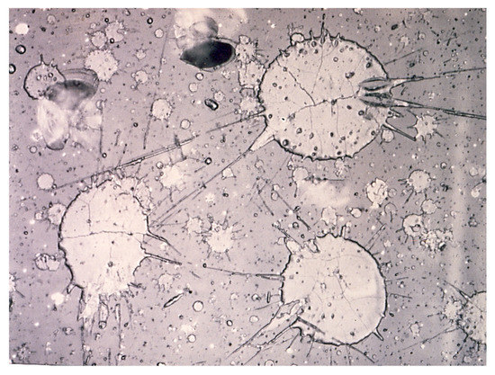
Figure 3.
Frozen-in-time traces of atmospheric plasma-sprayed alumina particles, showing ejection of matter assisted by the action of planar shock waves. The flow pattern and spreading are the result of a ‘wipe test’. © With permission by Wiley-VCH, Weinheim, Germany.
As shown in Figure 3, during a shock wave, material ejected on impact leaves behind tiny voids that will produce secondary microporosity in a coating. During impact, complex shock compression and rarefaction waves interact, generating non-equilibrium relaxation temperatures in hot spots that delay solidification and assist in improving adhesion to the substrate by forming a reaction boundary layer [30].
2.5. Heat Transfer Instability: The Trouble with Nonlinearity
Plasma spraying is a nonlinear process. Infinitesimally small changes of the input parameters may cause large and, in general, non-deterministic changes of the output parameters. Hence, the properties of the coatings and their eventual performance in service may be compromised by the fluctuation of plasma properties. Such nonlinear behavior arises from electromagnetic and magnetohydrodynamic turbulences. They affect the local magnetic field strength B and the electric current density j, and thus, the Lorentz force [j × B]. These turbulences cause the Lorentz force to fluctuate rapidly with frequencies that are in the order of the residence time of the particles in the jet, i.e., several tenth of microseconds. In lockstep with the fluctuating Lorentz force, the plasma compression, i.e., the magnetic z-pinch fluctuates. This affects the rate with which turbulent eddies of cool air surrounding the plasma column are entrained by the pumping action of the plasma jet. This process alters the temperature distribution within the turbulent plasma jet dramatically and instantaneously, causing the local thermal equilibrium to break down on a small scale compared to the overall volume of the plasma. Then, the system enters the realm of a heat transfer catastrophe of codimension two, i.e., a Riemann–Hugoniot (cusp) catastrophe [31]. This has severe consequences for the entire plasma spray technology because nonlinear and non-deterministic behavior cannot be properly controlled by even the most stringent quality control measures. In consequence, plasma spraying is still mostly an experimental technique based on trial-and-error methodology and relies heavily on experience and expert knowledge [7,32].
3. Selection of Plasma Spray Parameters
The selection of proper intrinsic and extrinsic plasma parameters is crucial for sufficient powder particle heating, flow, and surface wetting on impact, and hence, development of the desired coating characteristics, including porosity, cohesion within the coating, and adhesion strength to the substrate. However, it is well known to practitioners of plasma spraying that the measured properties can vary widely from coating to coating, despite the plasma spray parameters supposedly being set within narrow ranges by employing sophisticated microprocessor-controlled metering devices and stringent quality control measures. To ensure sufficient quality control, the statistical design of experiments (SDE) protocols, statistical process control (SPC), and Taguchi methodology are frequently being applied.
Among many intrinsic and extrinsic plasma spray parameters, care must be taken to control the position of injection of powder particles into the plasma jet. The locus of injection depends on the grain size and the grain size distribution of the powder, its melting temperature, and its thermal stability. The mode of injection of the powder material can be (i) perpendicular to the jet at the point of exit of the jet from the anode nozzle of the plasmatron (plasma ‘torch’) or beyond (Figure 1B), (ii) in upstream or downstream mode at an angle to the jet axis, (iii) directly into the nozzle, or (iv) coaxially through a bore in the cathode. Upstream injection may be applied when increased residence time of the powder particles in the jet is required, i.e., when spraying high refractory materials that is difficult to melt, such as zirconia. Downstream injection protects a powder with a low melting point from thermal decomposition and associated vaporization; for example, hydroxylapatite.
Statistical Control of Plasma Parameters
Practically, plasma spray parameters (variables) selected to optimize coatings thickness, porosity, cohesion and adhesion, or other relevant functional coating properties can be divided into highly significant ones, such as powder grain size, plasma enthalpy, and spray distance, and less significant ones, such as plasma gas pressure, powder feed gas pressure, or powder feed rate [33]. Although many more variables are known to affect the thermal history of powder particles, only eight to ten of the most important ones are selected in most studies designed to optimize coating properties.
Figure 4 shows the three-level hierarchy of eight plasma spray parameters and their effect on coating properties. The first level shows the plasma spray parameters Xi that control the second level temperatures of the plasma (X1 to X3), the particles (X4 to X6, X8), and the substrate (X7 and X8). The third level constitutes particle velocity, degree of melting, and degree of bonding. These properties directly influence the properties of the coating [34].
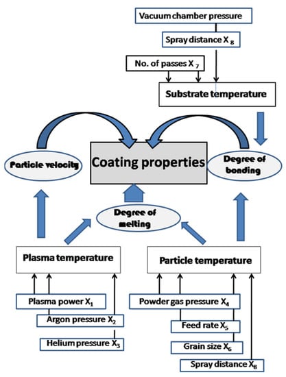
Figure 4.
Development of coatings properties, showing a three-level hierarchy of plasma spray parameters, temperatures of plasma, particles and substrate, and particle velocity, degree of melting, and degree of bonding [34]. © With permission by Wiley-VCH, Weinheim, Germany.
The interactions of plasma spray parameters X1 to X8, as shown in Figure 4, lead to complex relations that require judicious consideration when selecting their numerical values. For example, plasma parameters do not always act in the same direction, leading to characteristic saddle points of the response surface constructed from a statistical design matrix [35]. The statistical design of experiment (SDE) strategies are useful tools to control and hold (unwanted) parameter interactions in check. Figure 5a shows such a saddle point in the response surface contours of the average surface roughness Ra of plasma-sprayed Cr2O3 coatings deposited on a steel St37 substrate as a function of plasma power and powder grain size. Another saddle point (Figure 5b) was determined in the response surface of the coating thickness depending on substrate roughness and spray distance [7].
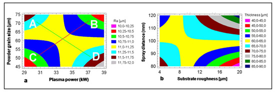
Figure 5.
Response surface contours of average surface roughness Ra (a) and thickness (b) of Cr2O3 coatings plasma-sprayed onto steel St37 surfaces using a 25−1 fractional factorial design. Panel (a): Average surface roughness Ra as a function of plasma power and powder grain size. Panel (b): Coating thickness as a function of substrate roughness and spray distance. © With permission by Wiley-VCH, Weinheim, Germany.
4. Design of Plasma-Sprayed Coatings
Recent decades have witnessed exciting developments in utilizing thermal plasmas to design a diverse range of coatings and interfaces. Presently, plasmas are widely employed to modify the surface properties of materials without changing their bulk properties. Many of these materials, coatings, and interfaces are unique and cannot easily be derived by conventional engineering techniques. Research fields and topics relevant to the design of next generation plasma-derived materials and coatings technology include:
- -
- Properties and performance of plasma-sprayed coatings: corrosion, mechanical, tribological, catalytic, biomedical, and/or electric evaluation;
- -
- Plasma-assisted thin film deposition;
- -
- Plasma etching and surface engineering;
- -
- Plasma texturing of surfaces;
- -
- Plasma spray-derived gradient and multilayers;
- -
- Plasma functionalization of surfaces;
- -
- Plasma spray-derived nanoscale coatings.
Strategic research tools to accomplish these tasks include stochastic approaches such as statistical design of experiments (SDE) methodology, artificial neuronal network analysis, fuzzy logic control, and others [35].
5. Challenges and Outlook
In recent decades, plasma spray technology has become an important tool of increasingly sophisticated surface engineering. Economically, the return of investment (ROI) in this segment of surface engineering is excellent. This means that small- and medium-sized enterprises (SMEs) will substantially benefit by entering a market that may be considered important with regard to materials technology of the 21st century.
However, to maintain the strategic advantage of plasma spray coating technology, strict quality control of advanced coatings is required, including close attention to the design and performance testing of coating/substrate systems. This must be combined with the development of novel structural and functional coatings, using improved automated equipment and comprehensive materials databases, expert systems, and realistic modeling and simulation protocols. Although these strategies provided plasma spray technology with a secure scientific foundation, it still is, essentially, a trial-and-error-based methodology: the nonlinear character of the process creates nondeterministic coating property behavior that cannot be precisely controlled even by the most sophisticated quality control and assurance measures. Experience and expert knowledge are the key to success.
Conflicts of Interest
The author declares no conflict of interest.
References
- Frank-Kamenetskii, D.A. Plasma: The Fourth State of Matter; Springer Science & Business Media: Berlin/Heidelberg, Germany, 2012. [Google Scholar]
- Burm, K.T.A.L. Plasma: The fourth state of matter. Plasma Chem. Plasma Process. 2012, 32, 401–407. [Google Scholar] [CrossRef]
- Goldston, R.J.; Rutherford, P.H. Introduction to Plasma Physics; CRC Press: Boca Raton, FL, USA, 2020. [Google Scholar]
- Smy, P.R. The use of Langmuir probes in the study of high pressure plasmas. Adv. Phys. 1976, 25, 517–553. [Google Scholar] [CrossRef]
- Vardelle, A.; Vardelle, M.; Fauchais, P. Influence of velocity and surface temperature of alumina particles on the properties of plasma sprayed coatings. Plasma Chem. Plasma Process. 1982, 2, 255–291. [Google Scholar] [CrossRef]
- Schoeneborn, P.R. The interaction between a single particle and oscillating fluid. J. Multiph. Flow 1975, 7, 307–317. [Google Scholar] [CrossRef]
- Heimann, R.B. Plasma Spray Coating. Principles and Applications, 2nd ed.; Wiley-VCH: Weinheim, Germany, 2008. [Google Scholar]
- Beard, K.V.; Pruppacher, H.R. A determination of the terminal velocity and drag of small water droplets by means of a wind tunnel. J. Atmos. Sci. 1969, 26, 1066–1072. [Google Scholar] [CrossRef]
- Fiszdon, J.K. Melting of powder particles in a plasma flame. Int. J. Heat Mass Transf. 1979, 10, 749–761. [Google Scholar] [CrossRef]
- Ranz, W.E.; Marshall, W.R. Evaporation form drops. Chem. Eng. Prog. 1952, 48, 141–146. [Google Scholar]
- Raithby, G.D.; Eckert, E.R. The effect of turbulence parameters and support position on the heat transfer from spheres. Int. J. Heat Mass Transf. 1968, 11, 1233–1252. [Google Scholar] [CrossRef]
- Chen, X.; Pfender, E. Heat transfer to a single particle exposed to a thermal plasma. Plasma Chem. Plasma Process. 1982, 2, 185–212. [Google Scholar] [CrossRef]
- Proulx, P.; Mostaghimi, J.; Boulos, M.I. Plasma-particle interaction effects in induction plasma modeling under dense loading conditions. Int. J. Heat Mass Transf. 1985, 28, 1327–1336. [Google Scholar] [CrossRef]
- Mostaghimi, J.; Proulx, P.; Boulos, M.I. An analysis of the computer modeling of the flow and temperature fields in an inductively coupled plasma. Int. J. Heat Mass Transf. 1985, 28, 187–201. [Google Scholar]
- Fauchais, P.; Vardelle, A. Heat, mass and momentum transfer in coating formation by plasma spraying. Int. J. Thermal Sci. 2000, 39, 852–870. [Google Scholar] [CrossRef]
- Golosnoy, O.; Tsipas, S.A.; Clyne, T.W. An analytical model for simulation of heat flow in plasma-sprayed thermal barrier coatings. J. Therm. Spray Technol. 2005, 14, 205–214. [Google Scholar] [CrossRef]
- Mostaghimi, J.; Chandra, S. Heat transfer in plasma spray coating processes. Adv. Heat Transf. 2007, 40, 143–204. [Google Scholar]
- Madejski, J. Solidification of droplets on a cold surface. Int. J. Heat Mass Transf. 1976, 19, 1009–1013. [Google Scholar] [CrossRef]
- Trapaga, G.; Szekely, J. Mathematical modeling of the isothermal impingement of liquid droplets in spraying processes. Metall. Mater. Trans. B 1991, 22, 901–914. [Google Scholar] [CrossRef]
- Dyshlovenko, S.; Pawlowski, L.; Pateyron, B.; Smurov, I.; Harding, J.H. Modelling of plasma particle interactions and coating growth for plasma spraying of hydroxyapatite. Surf. Coat. Technol. 2006, 200, 3757–3769. [Google Scholar] [CrossRef]
- Kang, C.W.; Ng, H.W. Splat morphology and spreading behavior due to oblique impact of droplets onto substrates in plasma spray coating process. Surf. Coat. Technol. 2006, 200, 5462–5477. [Google Scholar] [CrossRef]
- Mandelbrot, B.B. Self-affine fractals and fractal dimension. Phys. Scr. 1985, 32, 275. [Google Scholar] [CrossRef]
- Reisel, G.; Heimann, R.B. Correlation between surface roughness of plasma-sprayed chromium oxide coatings and powder grain size distribution: A fractal approach. Surf. Coat. Technol. 2004, 185, 215–221. [Google Scholar] [CrossRef]
- Heimann, R.B. On the self-affine fractal geometry of plasma-sprayed surfaces. J. Therm. Spray Technol. 2011, 20, 898–908. [Google Scholar] [CrossRef]
- Meakin, P.; Ramanlal, P.; Sander, L.M.; Ball, R.C. Ballistic deposition on surfaces. Phys. Rev. A 1986, 34, 5091. [Google Scholar] [CrossRef] [PubMed]
- Heimann, R.B.; Kleiman, J.I. Shock-induced growth of superhard materials. In Crystals. Growth, Properties, and Applications; Springer: Berlin/Heidelberg, Germany; New York, NY, USA; London, UK; Paris, France; Tokyo, Japan, 1988; Volume 11, pp. 1–73. [Google Scholar]
- Houben, J.M. Relation of the Adhesion of Plasma Sprayed Coatings to the Process Parameters Size, Velocity and Heat Content of Spray Particles. Ph.D. Thesis, Technical University Eindhoven, Eindhoven, The Netherlands, 1988. [Google Scholar]
- Heimann, R.B. Advanced ceramic coatings by plasma spraying: A technology for the 1990s and beyond. Process. Adv. Mater. 1991, 1, 181. [Google Scholar]
- Gruner, H. Vacuum plasma spray quality control. Thin Solid Films 1984, 30, 409–420. [Google Scholar] [CrossRef]
- Kitahara, S.; Hasui, A. A study of the bonding mechanisms of sprayed coatings. J. Vac. Sci. Technol. 1974, 11, 747–755. [Google Scholar] [CrossRef]
- Thom, R. Structural Stability and Morphogenesis: An Outline of a General Theory of Models; W.A. Benjamin: Reading, MA, USA, 1975. [Google Scholar]
- Heimann, R.B. A discussion on the limits to coating reproducibility based on heat transfer instabilities. J. Therm. Spray Technol. 2019, 33, 327–332. [Google Scholar] [CrossRef]
- Troczynski, T.; Plamondon, M. Response surface methodology for optimization of plasma spraying. J. Therm. Spray Technol. 1992, 1, 293–300. [Google Scholar] [CrossRef]
- Heimann, R.B.; Lamy, D.; Sopkow, T. Optimization of vacuum plasma arc spray parameters of 88WC12Co alloy coatings using a statistical multifactorial design matrix. J. Can. Ceram. Soc. 1990, 59, 49–54. [Google Scholar]
- Heimann, R.B. Better quality control: Stochastic approaches to optimize properties and performance of plasma sprayed coatings. J. Therm. Spray Technol. 2010, 19, 765–778. [Google Scholar] [CrossRef]
Disclaimer/Publisher’s Note: The statements, opinions and data contained in all publications are solely those of the individual author(s) and contributor(s) and not of MDPI and/or the editor(s). MDPI and/or the editor(s) disclaim responsibility for any injury to people or property resulting from any ideas, methods, instructions or products referred to in the content. |
© 2023 by the author. Licensee MDPI, Basel, Switzerland. This article is an open access article distributed under the terms and conditions of the Creative Commons Attribution (CC BY) license (https://creativecommons.org/licenses/by/4.0/).