1. Introduction
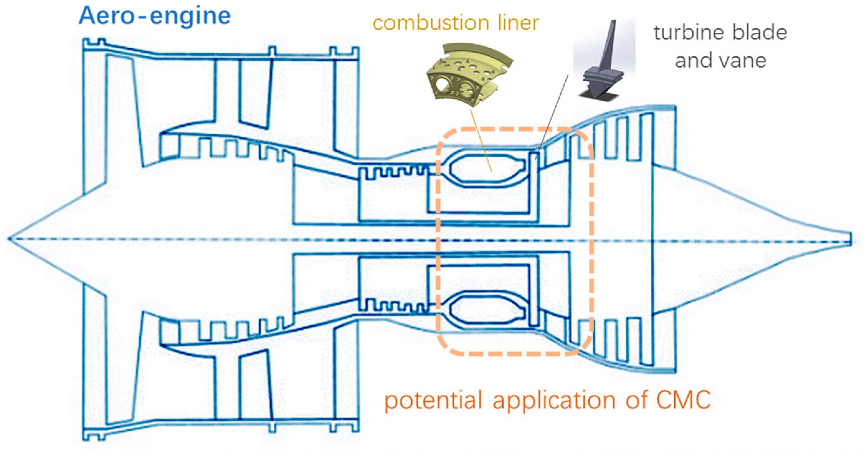
Ceramic matrix composites (CMC) have broad application prospects in aviation, aerospace, nuclear energy, and other fields, especially in the hot section components of aero-engines. The operation temperature of these hot end components of the new generation aero-engine will reach more than 1400 °C, which is far beyond the temperature range that the traditional superalloy materials can withstand. As an excellent high-temperature performance material, CMC is the most potential new thermal structure/functional material to replace superalloys. In aero-engines, CMC, represented by SiC
f/SiC, is mainly used in hot section components such as the combustion liner, turbine blade, and turbine vane, as shown in
Figure 1. This material can increase the operating temperature by 400–500 °C and reduce the weight by 50%–70% [
1,
2].
The SiC
f/SiC composite refers to the composite material in which SiC fiber is introduced into the SiC ceramic matrix as the reinforcement phase. By exerting the strengthening and toughening mechanism of the SiC fiber, the inherent defects of poor toughness and poor resistance to the external impact load of the material are overcome, which makes the material very suitable for the extreme environment of aero-engines [
3,
4,
5].
Under the operating environment of an aero-engine, the dense SiO
2 protective film formed by oxidation on the SiC
f/SiC surface will react with the water vapor to form volatile Si (OH)
x, mainly Si (OH)
4. The reaction process leads to the deterioration of the material performance and becomes one of the main factors restricting its application in hot end components of aero-engines [
6,
7,
8]. Generally, a layer of coating, called Environmental Barrier Coatings (EBCs), which is resistant to water oxygen corrosion, molten salt corrosion, and other environmental factors, is introduced on the surface of CMC components. The EBCs have been becoming a key technology for SiC
f/SiC composites to be applied to hot end components of aero-engines [
9,
10].
In other words, the EBCs are a partner of CMC when applied to aero-engines. The CMC component coated with EBCs is abbreviated as CMC/EBCs in the following part. It needs to be pointed out that commercial turbine aero-engines have started to use CMC/EBCs at some of the hot section components. According to Steibel [
11], CMC/EBC R&D has enabled the commercial introduction of CMC high-pressure turbine shrouds in the CFM International LEAP engine, which was certified by the Federal Aviation Authority and European Aviation Safety Agency (EASA) in May of 2016. In 2019, the CMC shrouds surpassed four million hours of flight time in commercial LEAP engines flying on Airbus (A320neo), Boeing (737 MAX), and COMAC (C919) aircrafts [
11].
Aero-engines are a kind of reusable high-speed rotating machinery. Both stator and rotor components bear complex loads during service. It is widely recognized that how to predict the failure of CMC will be one of the key technical challenges. Therefore, effective failure modeling is a key problem to be solved that determines whether CMC structures can be successfully applied to aero-engines, in addition to the fact that the manufacturing methods and materials need to be further improved.
With the increase of the operating temperature of hot section components of the aero-engine, the requirements for the performances of materials are becoming higher and higher. CMC/EBC’s integrated design plays a more important role [
12,
13]. Since CMC/EBCs are usually used in extreme service environments, coating peeling, cracks, and other damage phenomena are inevitable. At the same time, the internal microstructure of CMC/EBCs changes uncontrollably due to complex loadings, such as those at high temperature and high pressure. Therefore, it is very important to develop high-performance CMC/EBC systems under actual operating conditions, and it is also particularly important to develop failure prediction tools for this system. Developing CMC/EBCs with an excellent performance by the experimental method is a very complex and expensive process, and there are many unknown factors that need further exploration and long-term persistence. Failure models such as the finite element numerical simulation can help validate the experimental results and optimize the preparation process. In turn, it can shorten the development time and save costs. Failure models can help to find the optimal manufacturing method and material structures under specific target conditions [
13]. To develop CMC/EBCs, it is necessary to access relevant information and knowledge of the physical properties of various CMC and EBCs, the characteristics of defects and damages (pores and microcracks), and the relevant failure mechanisms. Then, effective prediction models can be established. For this purpose, many researchers have carried out a lot of research. This paper will discuss the relevant achievements and development trends in this field.
2. Development of Material System
2.1. Development of Ceramic Matrix Composites
This paper focuses on SiC
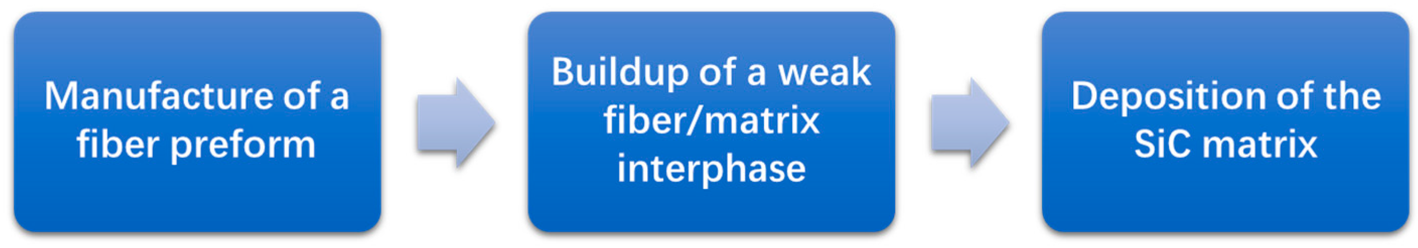
f/SiC composites with good application prospects in aero-engines, which are a kind of continuous fiber-reinforced composite. The manufacturing process of SiC
f/SiC composite components is shown in
Figure 2. The process can be divided into three stages.
Next, the characteristics and development status of the three constituents of SiCf/SiC composites—namely, SiC fiber, interphase, and ceramic matrix—are introduced. Then, the state-of-the-art components of the main manufacturing methods are also introduced.
2.1.1. Constituents
Mechanical responses and failure behaviors exhibited by composite materials subjected to different loading conditions really depend on the properties of their constituents.
SiC fiber is a kind of high-performance fiber product with great potential that develops rapidly after carbon fiber. It has excellent mechanical properties, high specific strength and a specific modulus, excellent heat resistance, excellent fatigue resistance, creep resistance, and reliability. Since SiC fiber has a good application prospect in aerospace, atomic energy, and other fields, the research on SiC fiber has become the focus of fiber research and also the focus of this paper. So far, three generations of SiC fibers have been successfully commercialized. Their key properties are shown in
Table 1. As seen, the third-generation SiC fiber is mainly represented by Hi-Nicalon S fiber, Tyranno SA fiber, and Sylramic fiber. The third-generation SiC fiber has improved the densification degree, high-temperature resistance, oxidation resistance, and creep resistance and can maintain stability in the atmospheric environment of 1300~1800 °C [
5].
There are two issues when selecting the ceramic matrix: (1) the ability to protect the fiber and bear the load under high temperature and (2) the stability of the material under the combustion gas environment and complex load. These two aspects are related to the properties of ceramics. That is, the matrix needs excellent corrosion resistance and good interface compatibility. The molding performance of ceramics and the bonding performance between the matrix and fiber will affect the properties of CMC [
16].
Non-oxide ceramics are mainly chosen as matrix materials for CMC in aero-engines. Non-oxide ceramics mainly refer to SiC and Si
3N
4. They both have good corrosion resistance, oxidation resistance, and high strength. By contrast, the sintering temperature of Si
3N
4 is relatively lower than SiC. Therefore, the SiC matrix has very broad application prospects. Pure SiC ceramics are mainly obtained by the high-temperature pyrolysis of polycarbosilane or chemical vapor deposition of trichloromethylsilane, while the SiC matrix of CMC composites is modified by doping other elements into pure SiC ceramics [
17].
As the transition zone of the load transfer between fiber and matrix, the bonding strength, bonding mode, and the interphase type have a great impact on the mechanical properties and failure mode of CMC. The existence of a weak interphase enables the introduction of crack deflection at the fiber/matrix bonding system, which can cause a nonductile fracture [
18].
At present, the widely used interphases are the fiber treatment by pyrolytic carbon (PyC) and boron nitride (BN). The PyC interphase acts as a weak interface between the fiber and matrix to improve the fracture toughness. It is usually prepared by the chemical vapor infiltration method or resin impregnation pyrolysis method. The BN interphase is different from the PyC, as the BN can protect fibers from oxidation. That is, the CMC with the BN interphase has better oxidation resistance than the PyC [
19]. The preparation methods for the BN interphase also include chemical vapor infiltration and precursor impregnation pyrolysis. Although the PyC and BN interphases have been widely used in C
f/SiC and SiC
f/SiC composites, the targeted research has still been in progress in recent years. These two kinds of interphases have poor oxidation resistance when water vapor exists, which is the universal environment within aero-engines. A better choice is the multilayer interphase, which contains different sublayers, such as (PyC/SiC)n and (BN/SiC)n. As the sublayers of different constituents combined, integrating the advantages of both, they are adapted to the application under a combustion gas environment [
20].
2.1.2. Manufacturing Methods
Different manufacturing methods will lead to different failure characteristics. The preparation processes of SiCf/SiC composites mainly include polymer infiltration and pyrolysis (PIP), chemical vapor infiltration (CVI), and melt infiltration (MI).
The PIP was invented to prepare C
f/C composites with an asphalt or resin polymer precursor and then gradually extended to CMC preparation. The liquid precursor is pyrolysis at high temperatures under inert gas protection or a vacuum environment and converted into the ceramic matrix in situ. The preparation temperature of PIP is relatively low, with little damage to the fibers. The process is of strong designability of the ceramic matrix and easy-to-manufacture large and complex components. Its disadvantages lie in the large shrinkage of the matrix, which introduces high porosity. Therefore, the latest efforts are focusing on developing a precursor with a high ceramic conversion rate or filler that can be used to optimize the process [
2,
21].
The CVI method is developed from Chemical Vapor Deposition (CVD). It is very similar to CVD. The traditional CVD method is to directly deposit coatings on the surface of the substrate material, while the CVI method involves the problem of reactive gas penetration, which is to generate solid ceramic materials inside the material preform and deposit them on the internal fiber surface in the form of coatings [
22]. The materials prepared by the CVI process have high purity, a complete crystal structure, and excellent mechanical properties. The disadvantage is that CVI has a long preparation period and results in a high cost. To improve the deposition efficiency, researchers have developed forced flow thermal gradient technology, whose mass transfer process is realized by forced convection. The efforts are focusing on methods that can improve the deposition efficiency and shorten the densification cycle [
23].
The MI is a process in which the melt enters porous preforms spontaneously without external force employing capillary pressure generated by wetting. The metal melt infiltration method is that ceramic powder is first made into preforms through a certain sintering process, and the metal melt or intermetallic compound melt spontaneously infiltrates into the ceramic preforms at high temperatures to form sintered products. The MI process has obvious advantages, such as low manufacturing cost, short cycle, and low porosity. The disadvantage of this process is that the reaction temperature of liquid phase siliconizing is high (generally higher than 1400 °C), which is higher than the long-term service temperature of the current SiC fibers and will cause damage to SiC fibers [
24,
25].
2.2. Development of Environmental Barrier Coatings, EBCs
As discussed in the literature [
26,
27,
28,
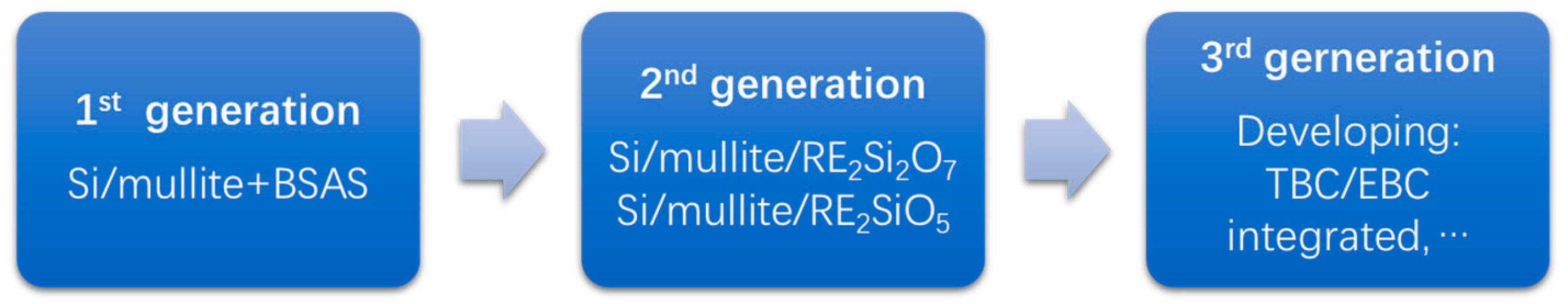
29], the development of EBCs is generally categorized into different generations based on the main composition being used as shown in
Figure 3. A more detailed review of the different generations is presented in this section, with a particular focus on the capabilities and their pros and cons.
Mullite attracted the earliest interest because of its good coefficient of thermal expansion, CTE, and match and chemical compatibility with the ceramic matrix of CMC. However, mullite does not have long durability in the steam environment. While the barium–strontium–aluminosilicate (BSAS) is of improved thermal cycling durability and has a low silica activity, good CTE match with SiC, and a low modulus. In addition, the introduction of a Si bond coat can further improve the cycling life of coatings [
26]. Therefore, Si/mullite + BSAS/BSAS EBCs were applied on SiC
f/SiC CMC as the first generation.
The new generation of aero-engines requires EBCs with higher temperature capabilities. Owning high stability in water vapor, high melting points, and a close CTE match with CMC, rare earth silicates were selected as prime candidates. The rare earth silicates can be classified as monosilicates (RE
2SiO
5) and disilicates (RE
2Si
2O
7), where RE = rare earth elements [
27,
28]. For this reason, Si/mullite/RE
2SiO
5 and RE
2Si
2O
7 were selected as the second generation of EBCs.
The operating temperature of aero-engines is still rising to achieve more powerful thrusts. Focusing on the development and application of CMC components in the future aero-engines, the design concept of thermal/environmental barrier coatings (T/EBCs) has been proposed in combination with TBC coating as the next generation of EBCs. A thermal barrier layer is introduced to further improve temperature resistance to protect the CMC/EBCs in a steam environment up to 1650 °C [
29].
2.3. Integration of CMC/EBCs
EBCs are different from thermal barrier coatings (TBCs). TBCs are mainly used to protect the superalloy component. The superalloy substrate has better oxidation resistance than CMC. The TBCs are introduced as insulating materials to further widen the usage range of operating temperatures for superalloys. TBCs usually contain materials with low thermal conductivity coatings that can reduce the surface temperatures of superalloy components coated with TBCs [
30,
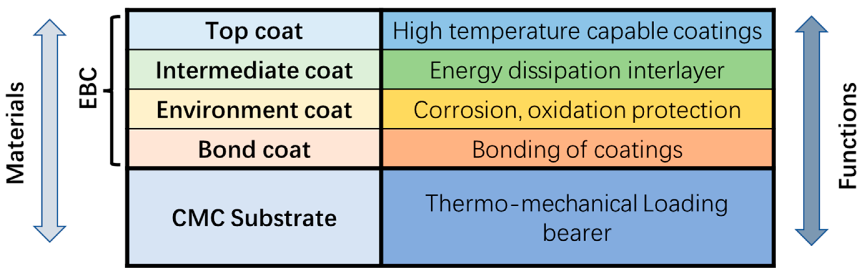
31]. Formerly, the main function of EBCs is to resist the corrosion of the CMC substrate in the combustion gas environment. With the development and progress in technology, more functions have been introduced, as shown in
Figure 4. According to the latest design concept of EBCs, there are four sublayers of coatings. The top coat is designed as a high-temperature capable coating. Then, the intermediate coat is used to dissipate thermal–mechanical energy. Next, the environment coat acts as a corrosion and oxidation barrier. Finally, the bond coat bridges the two materials at the coating/CMC interface. These functions lead to a closer connection between the coatings and substrate. Meanwhile, the integration of the CMC substrate and EBCs becomes a more challenging work. The latest efforts are focusing on optimizing EBC technologies and making the coatings concordant with the CMC substrate. There is also a continuous push for developing methods that can design CMC/EBCs integrally.
3. Failure Mechanism
3.1. Failure Mechanism of Ceramic Matrix Composites
CMC is a typical brittle matrix material. Generally, the fracture strain of the fiber (1%~1.5%) is greater than that of the matrix (0.1%~0.2%), and the CTE of the matrix is generally greater than that of the fiber. When cooled down after preparation, there will be tensile stress in the matrix and compressive stress in the fiber, leading to the initial damage of the material, such as matrix cracking and interface debonding. Under the mechanical load, the matrix cracks act as damage sources. With the increasing static and cyclic loads, the matrix cracks will continue to propagate. When a crack arrives at the interface between the fiber and the matrix, its propagation path depends on the relative strength of the interface and the fiber. If the interface is strong, the crack penetrates into the interphase and the fiber, leading to a fiber break. As a result, the composite exhibits brittle fractures similar to that of monotonic ceramics. In contrast, the crack will deflect at a weak interface. The crack propagates along the fiber/matrix interface, and the fiber will not fracture. The fiber bridging mechanism plays a part that leads to the pseudo plasticity failure behavior of the material. Around 2000, it was recognized and widely accepted that matrix cracking, interfacial debonding, and fiber fractures were the three basic damage modes of unidirectional CMCs [
32].
The above is a typical failure process of unidirectional fiber reinforced CMC. For CMC with complex fiber preforms, such as woven and braided CMC, the failure process becomes more complicated. In addition, there are more voids and defects in the woven and braided composite. The matrix cracking may occur under very small strain in these woven and braided CMCs. It has been proven that cracks first occur in the matrix-rich area of the material [
33]. On the other hand, there are more abundant toughening mechanisms within the complex fiber preform, such as the pull-out of the fiber bundle. As the load-bearing phase of CMCs, fibers can resist the propagation of matrix cracks perpendicular to the fiber. The configuration, alignment, and orientation of fibers in the woven and braided composite are more complicated. Thus, the damage mode and failure process will change accordingly.
As mentioned, CMC is the leading material candidate for the hot section component of aero-engines subjected to an extreme temperature–time–oxidative environment. It is important to figure out the influences of cyclic loading, thermal shock, oxidation, etc. on the failure behavior of the composite. In addition, the composite structures usually serve in a mixed-mode loading or coupling environment that induces more complex failure behavior, such as crack propagation under fatigue loading and crack healing under an oxidation environment. Lots of effort has been contributed to illustrate the results of an extensive experimental investigation on the static and fatigue crack propagation, creep behavior, oxidation, and corrosion of composite materials over the past decades [
34,
35,
36,
37].
In general, relevant studies have shown that the interphase, preparation process, fiber architecture, loading mode, etc. will have a significant impact on the failure mechanism of CMC [
38,
39,
40,
41]. Therefore, it is necessary to fully consider all the damage modes, as well as the effect of these factors on the failure mode of CMC.
3.2. Failure Mechanism of Environmental Barrier Coatings, EBCs
To design and optimize the materials and microstructure of EBC coating, a comprehensive understanding of the physical and chemical properties, the damage modes of EBC coatings, the driving force, and other factors are necessary. Therefore, most efforts in EBC study have been focused on the failure mechanism, involving the material preparations, damage evolution, failure mode, and life prediction. After several years of study, no substantial progress has been made in the failure mechanism of EBC coatings. Accordingly, the results only point out that the failure of EBC coatings is in all probability caused by the following aspects [
42,
43,
44,
45,
46,
47,
48,
49,
50,
51,
52]:
Thermal residual stress caused by the mismatch of CTE between the coating sublayers and CMC substrate;
Microcracks, voids, and other defects in the coatings and substrate;
Oxide layer;
Sintering and shrinkage of the coating;
The degeneration of the bonding layer;
Mechanical damage, such as delamination and spalling.
Nevertheless, many researchers remain dedicated to revealing the failure mechanism of EBC coatings. J Kimmel et al. [
42] conducted an experimental study of a SiC
f/SiC combustion liner coated with a BSAS coating system. They found that, after exposure to the gas environment for 13,937 h, the coating spalled off in a large area. They pointed out that spalling is one of the main damage modes that cause the failure of EBC coatings during long-term service. In their observations, widely distributed through-thickness cracks in the coating were found. Ai et al. [
44] performed EBC tests under thermal cycles without mechanical loads. They found that, when the penetrating cracks initiated in the top coat propagate to the intermediate coat, transverse debonding cracks occur at the interfaces between sublayers of coatings—specifically, the interface between the intermediate coat and bond coat and the interface between the bond coat and CMC substrate. These debonding cracks propagate and coalesce with each other, leading to the final spalling of the coatings. Meanwhile, voids and oxidation in the coating will accelerate the failure procedure of EBC coating.
Other studies focused on the CTE mismatch between coating sublayers and substrate. It was found that the water oxygen corrosion may gradually diffuse to the substrate surface and reacts with the CMC, eventually forming a large number of pores at the coating/substrate interface when the CTE of the EBC coatings is very close to that of the CMC substrate. These pores grow and interconnect; then, the EBC coatings spall from the CMC substrate [
46]. That is, cracks and pores in EBC coatings play a very important role in the failure procedure of EBC coatings.
In addition, the behavior of EBCs under thermal shock, thermal gradients, and a corrosion environment directly affects the service life and stability of the coatings and substrate. Lots of studies had been conducted to investigate the failure mechanism of EBCs under such an environment [
48,
50,
53,
54]. Within these studies, the performances of EBCs were tested using a high-temperature induction furnace, specially designed electric furnace, and burner rig facilities. Obviously, the burner rig facility can provide combustion gas similar to actual working conditions, which is the best method to test the performances of the EBCs. Meanwhile, the phase analysis and the surface topography observation are usually performed to obtain the characteristics the EBCs during the loading procedure. The results will be helpful to improve the performance and service life of EBCs in a high-temperature extreme environment.
3.3. Failure Mechanism of CMC/EBCs
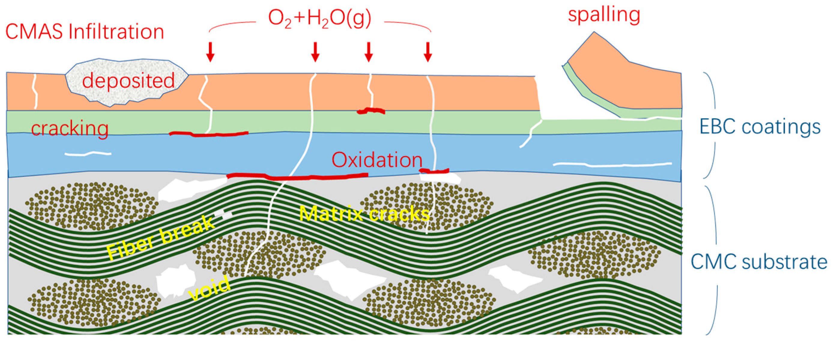
As discussed, most efforts have been devoted to studying the failure modes of CMC and EBCs, respectively. However, the damages within the CMC substrate and EBC coatings influence each other and also the parallel development. As shown in
Figure 5, fiber breaks and matrix cracks may occur under the thermomechanical load, while cracking and oxidation take place due to the steam environment. Following this, the propagation of cracks in the substrate and coatings may influence each other and coalesce with one another. The fibrous architecture of the CMC substrate plays an important role in the damage mode of EBCs. Similarly, the layer properties of coatings also have a significant impact on the failure process of the CMC substrate. Thus, it is necessary to consider the synergetic effect of coating properties and substrate fibrous architecture when analyzing the failure mechanism of the CMC/EBC system.
4. Failure Modeling
4.1. Failure Modeling of Ceramic Matrix Composites
The failure prediction of composite materials is usually referred to using single or multiple models to calculate the stress/strain states and simulate the damage evolution. The failure can be determined by different criteria. Different mechanisms such as fiber failure, matrix cracks, interfacial debonding, and delamination can be considered within the criteria. The failure prediction for fiber-reinforced composites is necessarily based on an accurate determination of the microscale stress/strain states. For example, the shear stress at the fiber/matrix interface is significantly important to estimate the initiation and propagation of debonding between fiber and matrix. To accurately and efficiently calculate the stress/strain states within the composites, different types of methods have been proposed over the decades. Among them, the progressive damage analysis based on the micromechanics method is the most widely used.
In early studies, the macro-mechanical model [
55] was applied to analyze the behavior of the CMC structure. However, these models based on the elastoplastic mechanics, which are usually used for metal materials, are not actually applicable to the CMC. As known, the concept of plasticity cannot be directly used to describe the mechanical behavior of the CMC material. To describe the nonlinear characteristics of CMCs, researchers have introduced variables characterizing microscale damage into the constitutive equation [
56,
57]. Damage variables are in the form of scalar or tensor. By fitting the test data, these models can well describe the nonlinear behaviors of CMCs.
The homogenization method provides a feasible way to establish a mechanical model that can build the quantitative relationship between macroscale properties and the microstructure of the composite. The homogenization method decomposes the composite into different scales, and a mechanical analysis can be executed at each scale separately. It has been realized that the deformation and stress field of composites at different scales is clearly different. Accordingly, the method to determine the bulk deformation behavior from the local response is necessary. Such methods refer to the homogenization algorithms, which usually conduct over a specifically selected volume of the composite [
58]. Then, the relationship between different scales can be developed through homogenization methods. From another perspective, the homogenization method is a numerical procedure for predicting the elastic properties of the composite from the available elastic properties of the constituents. This procedure often involves generating a model, applying appropriate boundary conditions on the model, and calculating the average stress and strain of the model volume [
59,
60]. As known, the different properties of the constituents, such as the fiber, matrix, and interfacial region, cooperatively influence the thermomechanical properties of composite materials. Therefore, the underlying random microstructure and the uncertainties of the constituents’ properties could be accounted for to conduct reliable failure predictions for composites using the homogenization method [
61].
According to the methodology of the homogenization method and micromechanics, a representative volume element (RVE) is widely used for the modeling of composite materials. RVE is the basic unit or element of the material, capturing all details of the microstructure. Generally, RVE is referred to as a repeating unit cell (RUC) for composites. Meanwhile, RUC is often used to model materials that show periodic characteristics. It should be mentioned that the asymptotic homogenization theory has been developed by Raghavan et al. [
62] to describe the characteristics mathematically of periodic composites. RVE models are used with the FE analysis to determine the mechanical properties and also to study the damage mechanisms of composites. So far, the concept of RVE has been successfully implemented as the underlying concept in homogenization techniques for the failure analysis of a composite [
63,
64]. Ismar et al. [
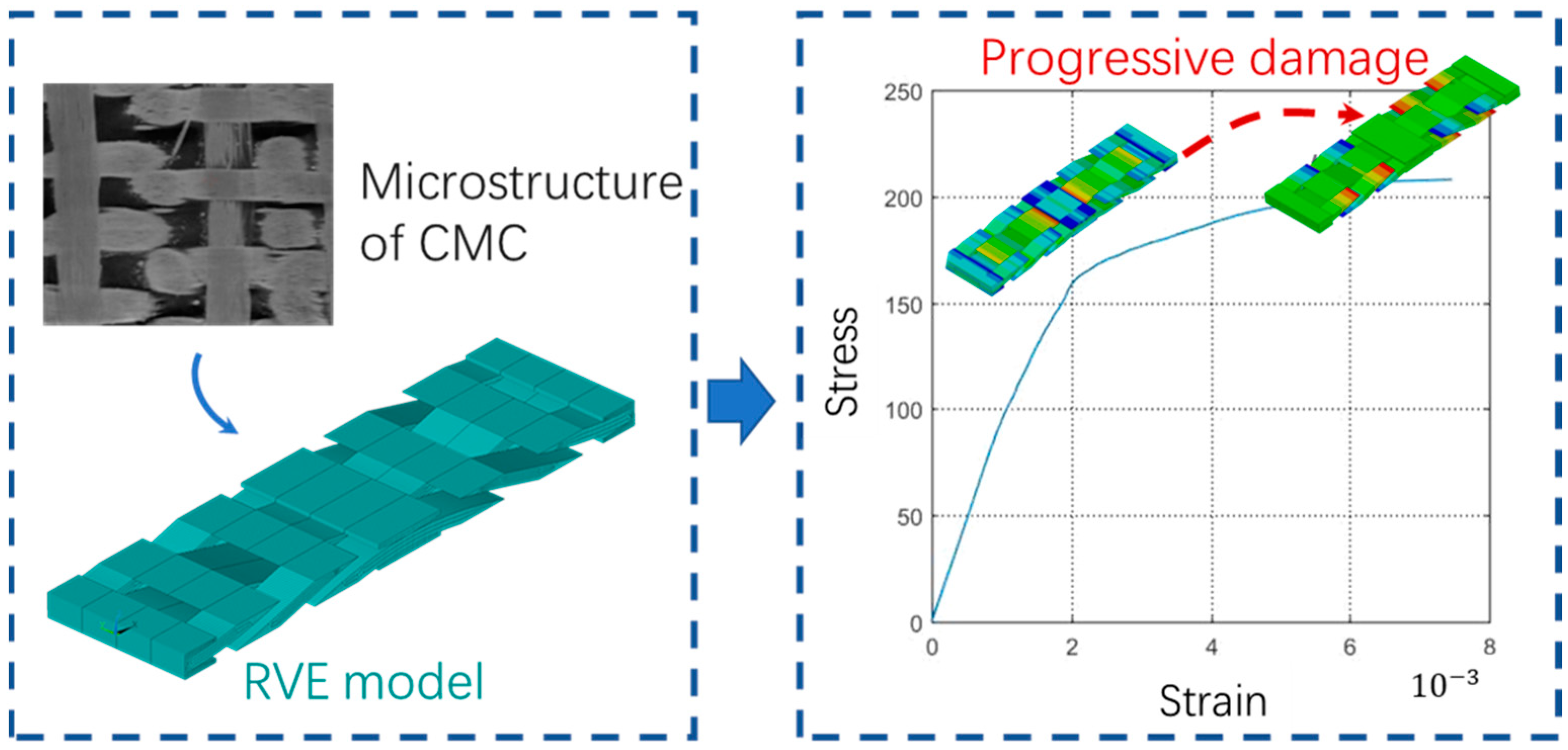
65] established a representative volume element (RVE) model considering the fluctuation of both warp and weft yarns. In the RVE, the transverse cracking of the matrix and debonding between yarns was introduced by defining the fracture criteria. The gradual degradation process of yarn properties along the fiber direction was described using damage variables. Then, a simulation of the nonlinear behavior of a braided CMC under tensile loading can be carried out. A model framework such as this is the most effective and widely accepted right now. As shown in
Figure 6, a typical example of the failure analysis of CMC is a combination of the progressive damage simulation and micromechanical RVE concept.
Based on this framework, different factors that have impacts on the failure behavior of CMC can be modeled [
8,
66]. For example, most of the latest efforts have been devoted to studying the effects of voids, manufacturing defects, fiber architectures, etc. on the failure of CMC.
4.2. Failure Modeling of Environmental Barrier Coatings, EBCs
The failure of the EBCs is a gradual progress when subjected to actual service conditions. As discussed in the previous section on failure mechanism, the final failure of EBCs is often related to the thermal residual stress, sintering effects, oxidation, and so on. However, overall, the failure is often attributed to the initiation and propagation of cracks and the associate stress state, cyclic loading, and temperature. Therefore, the failure prediction of EBCs is usually referred to using analytical or numerical models to calculate the stress/strain states and simulate the cracking propagation. Different factors such as thermal residual stress, sintering effects, and oxidation need to be considered within the model [
67,
68]. The failure prediction for EBCs is necessarily based on an accurate description of these factors and their effects.
However, the factors that can affect the failure modes and lifetimes of the EBCs are very complicated and unpredictable. For instance, the CTE mismatch of different sublayers and substrates will cause nonignorable thermal residual stress in the coatings. Further, different bonding strengths between sublayers may lead to delamination nonuniformly and randomly. There are many methods to account for the effects of these factors on the cracking behavior of EBCs [
69,
70,
71,
72]. Generally, the cracks within EBCs can be classified into two categories according to their orientation: horizontal cracks and vertical cracks. In much of the research, the mentioned factors were modeled using analytical or numerical methods to figure out their impacts on the two kinds of cracks.
As discussed, the loading mode and service environment play an important role in the damage evolution. They should be taken into account when building the failure model. For most high-temperature applications, thermal shock, or thermal cycling is inevitable. Therefore, it is necessary to investigate the transient stress distribution and stress evolution in the EBCs. Transient FEA is capable of capturing the dynamics of thermal shock and has been applied to analyze the tangential stress distribution and evolution in EBCs [
73]. The influences of thermal gradient, creep relaxation, and oxide growth on the failure of EBCs were also investigated using an analytical model or FEA [
74].
In addition, the oxidation of the bond coat (usually, Si BC) takes place between the coatings and the CMC substrate under the steam environment of the aero-engine. This issue also plays a significant role in the failure behavior of the EBCs. The oxidation products have a different CTE compared to the original bond coat. Thermal mismatch due to CTE between these constituents will induce large residual stress near the interface. The thermal residual stress tends to increase with the oxidation process [
75,
76,
77]. As a result, the cracks initiate nearby. The final failure modes will be very complicated due to the coexistence of the cracks and the oxidation.
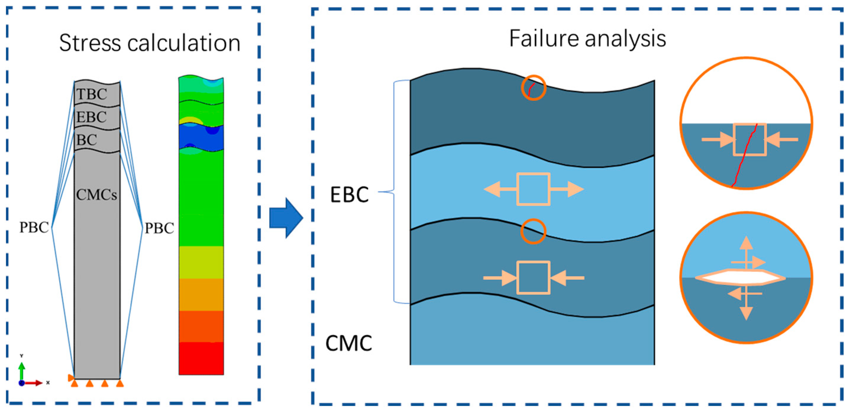
As shown in
Figure 7, FEM is an efficient method to solve the failure problems of the EBCs associated with cracking. Firstly, the voids, interfacial defects, and other geometry factors can be captured in well-constructed geometry models. Subsequently, the FE models are capable of considering the differences between the physical properties of constituents [
78]. Then, it is convenient to simulate the initiation and propagation of cracks by various methods integrated into the FE analysis, such as VCCT and XFEM. For instance, the author conducted a numerical study of the effect of the roughness interface on thermal stress in the EBCs [
79]. A micromechanical RVE model of the coated composites was established and calculated using the FE method. One of the mentioned factors, the rough interfaces between the coating layers, was considered in the model. The distribution of thermal residual stress and the stress concentration was analyzed. The latter is prone to causing delamination cracking. Then, the cracking patterns and their influencing factors were discussed.
4.3. Failure Modeling of CMC/EBCs
As mentioned, most efforts have been devoted to developing the failure models of CMC and EBCs, respectively. However, the damages within the CMC substrate and EBCs coating influence each other and also the parallel development [
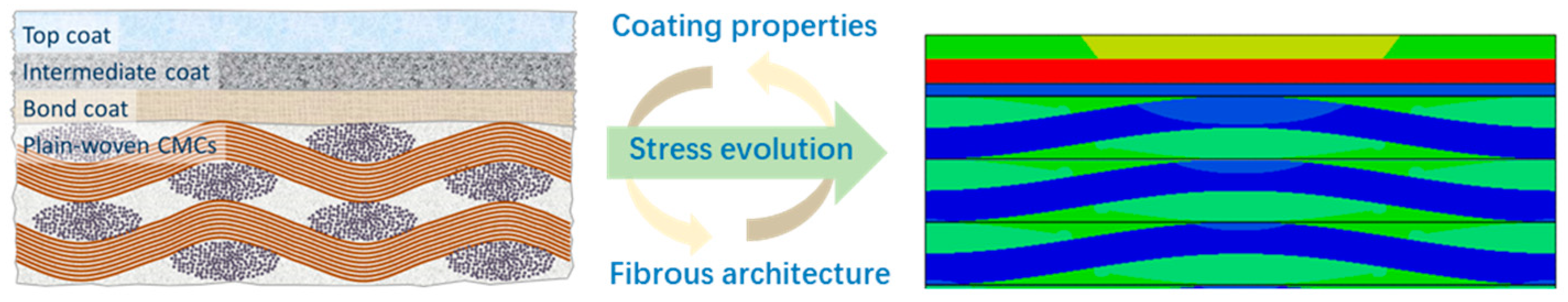
80]. An ideal model for the failure prediction of CMC/EBCs must consider the synergetic effects of coating properties and substrate fibrous architecture. Unfortunately, there are not many such models. Based on this, a previous work of the author developed a numerical model to study the synergetic effect of coating properties and fibrous architecture on the evolution of thermal stress within a CMC/EBC system [
81]. The microstructures of both EBC coatings and CMC substrate were precisely modeled in a FE model, as shown in
Figure 8. The results show that both the layer properties of the coatings and the fibrous architecture of the composite substrate have significant impacts on the stress distribution. Thus, it can be concluded that an adequate failure model for the CMC/EBC requires a realistic representation of the fibrous architecture, as well as the coating layers. However, the former is usually ignored in most studies.
5. General Remarks on Technical Development
The CMC is a kind of material compounded by brittle fibers, brittle matrix, and interphase. Although the fiber and matrix of CMC are elastic, the composites exhibit nonlinear characteristics, also noted as pseudoplasticity. The fracture process and cracking mode are also very complicated due to the various microscale damages, such as fiber break, matrix cracking, interfacial debonding, etc. It should be noted that these macroscale mechanical behaviors are closely related to the microstructure of preform and physical properties of constituents as the CMC is of significant heterogeneity.
As an excellent high-temperature performance material, the SiCf/SiC composite is the most potential new thermal structure/functional material to replace superalloys. The complex mechanical behavior of this kind of CMC has aroused great interest in many researchers. The basic failure mechanism has been revealed. Most of the latest efforts have been devoted to figuring out the main factors that influence failure behaviors under service conditions of aero-engines.
On the other hand, the EBCs are developed to increase the service life of SiCf/SiC components in the gas environment. There are high durability and reliability requirements for the components in the aero-engine in order to reduce the operating and maintenance costs. The improvement of the durability of EBC coatings can effectively increase the service life of SiCf/SiC components. Therefore, how to improve the durability of EBCs coatings has always been an important perspective of the CMC study.
In the as-processed state, EBCs are well-bonded to the CMC substrate. However, as these coatings are exposed to the steam environment, various damages appear, such as cracking, oxidation, spalling, etc. Thus, most of the efforts are focusing on identifying the damage mode and the related factors.
The failure mechanism of a CMC/EBC system is summarized in
Figure 9. As seen, the damage modes of the CMC substrate can be divided into intralaminar and interlaminar, while the damage modes inside the EBCs contain thermomechanical and environmental damages. The details can be found in the figure. It should be noted that the damages within the CMC substrate and EBC coatings influence each other. As discussed, most of the existing research has studied the failure modes of CMC and EBCs, respectively. Thus, it is necessary to pay more attention to considering the synergetic effect of the coating properties and substrate fibrous architecture when analyzing the failure mechanism of the CMC/EBC system.
Compared to the experimental studies, model research on the failure of CMC/EBCs is inadequate. As mentioned, many experimental studies have been conducted to figure out the main factors that influence the failure behavior of CMC under service conditions. Meanwhile, tests are performed by exposing the EBC to a variety of service environments, including isothermal dry air exposures, exposures to water vapor, and cyclic thermal exposures. These experimental studies that intended to capture the key factors that influence the failure are necessary pre-works for developing prediction models. However, the influence factors are too complicated. There are still many issues that are not clear within the failure mechanism of the CMC/EBC system. As a result, the progress of model research is relatively slow and not meeting expectations.
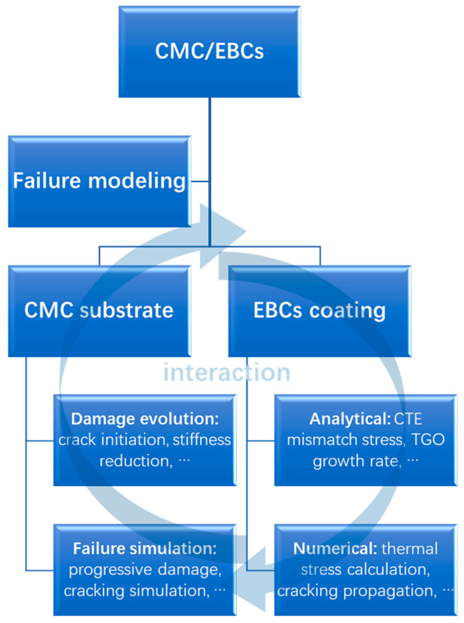
According to the published literature, most of them intended to develop failure models of CMC and EBCs, respectively. The typical modeling methodology of the CMC and EBCs is summarized in
Figure 10. As seen, the failure analysis of CMC is a combination of the damage evolution and failure simulation. The simulations are usually based on progressive damage analysis and the micromechanical RVE concept, while the failure models of the EBCs can be divided into analytical and numerical methods. The particular method is selected to calculate the thermal residual stress or to simulate crack propagation. Similar to the technical trends of mechanism study, more attention should be paid to developing models that consider the synergetic effects of coating properties and substrate fibrous architecture for the failure prediction of CMC/EBCs. As demonstrated by a previous study, an adequate failure model for the CMC/EBCs requires a realistic representation of fibrous architecture, as well as the coating layers.
6. Conclusions
To improve the durability of CMC/EBCs in the combustion gas environment, different manufacturing methods of composites and several generations of coating systems have been developed over the past 40 years. Most of the efforts were devoted to optimizing the preparation process and obtaining the detailed performance data of these materials under the combustion gas environment of the aero-engine.
Individually assessing the failure of CMC and EBCs is not a simple task. Before modeling, tests under severe and typical operating environments need to be performed to capture the damage modes and failure mechanisms. Then, models should be developed to consider the factors that influence the characterization of these materials. Among these factors, the most important ones are voids, manufacturing defects, fiber architectures, loading mode, and service environment. Most efforts have been devoted to simulating and modeling the influences of these factors on the CMC and EBCs, individually. Indeed, more efforts should focus on researching the interaction and coupling effect of these factors.
Therefore, this paper offers a review and a detailed description of the materials features, failure mechanism, and failure modeling for both CMC substrate and EBCs coatings. A discussion of the various methods for failure analysis is performed. General remarks on technical development for failure modeling are summarized subsequently. So far, the failure analysis of CMC and EBCs is still a challenging task. There is no clear and complete map for the mechanism and influence factors of the CMC and EBCs. In addition, an adequate failure model for the CMC/EBCs requires more details of the CMC substrate as well as the EBCs coating as the damage evolutions within them influence each other. In fact, both the layer properties of EBCs and the fibrous architecture of the CMC substrate have significant impacts on stress distribution and damage evolution in the coated system. There is an interactive relationship between the development of stress and damage in the coatings and substrate. In addition, other factors such as manufacturing defects in the coatings and substrate affect each other. However, most previous research intended to develop failure models of CMC and EBCs, respectively. Therefore, more attention should be paid to the synergetic effect of coating properties and substrate fibrous architecture.
Author Contributions
Conceptualization, G.F., X.G. and Y.S.; methodology, G.F., X.G., and Y.S.; writing—original draft preparation, G.F.; writing—review and editing, G.F.; visualization, G.F.; project administration, X.G. and Y.S.; and funding acquisition, X.G. and Y.S. All authors have read and agreed to the published version of the manuscript.
Funding
This research was funded by National Science and Technology Major Project, grant number Y2019-I-0018-0017.
Institutional Review Board Statement
Not applicable.
Informed Consent Statement
Not applicable.
Data Availability Statement
The data that support the findings of this study are available upon reasonable request from the authors.
Acknowledgments
The authors acknowledge the support from Jiangsu Province Key Laboratory of Aerospace Power System and Key Laboratory of Aero-engine Thermal Environment and Structure, Ministry of Industry and Information Technology. The authors also wish to thank Tang Huahua and Fang Yiru for their help in interpreting the significance of the results of this study.
Conflicts of Interest
The authors declare no conflict of interest.
References
- Liu, Q.; Huang, S.; He, A. Research progress in environmental barrier coatings of SiC ceramic matrix composites. J. Mater. Eng. 2018, 46, 1–8. [Google Scholar]
- Okita, Y.; Mizokami, Y.; Hasegawa, J. Erosion Testing of Environmental Barrier-Coated Ceramic Matrix Composite and Its Behavior on an Aero-Engine Turbine Vane Under Particle-Laden Hot Gas Stream. J. Turbomach. 2020, 142, 061001. [Google Scholar] [CrossRef]
- Fitzgerald, K.; Shepherd, D.; Fitzgerald, K.; Shepherd, D.; Fitzgerald, K.; Shepherd, D. Review of SiCf/SiC m corrosion, erosion and erosion-corrosion in high temperature helium relevant to GFR conditions. J. Nucl. Mater. 2017, 498, 476–494. [Google Scholar] [CrossRef]
- Liu, X.; Wang, R.; Hu, D.; Zhang, L.; Chen, G. Degradation analysis on high-cycle bending fatigue for woven SiC/SiC composites based on Wiener process model. Mater. Des. 2021, 198, 109295. [Google Scholar] [CrossRef]
- Wang, P.; Liu, F.; Wang, H.; Li, H.; Gou, Y. A review of third generation SiC fibers and SiCf/SiC composites. J. Mater. Sci. Technol. 2019, 35, 2743–2750. [Google Scholar] [CrossRef]
- Pailler, F.; Lamon, J. Micromechanics Based Model of Fatigue Oxidation for Ceramic Matrix Composites. Compos. Sci. Technol. 2005, 65, 369–374. [Google Scholar] [CrossRef]
- Yu, G.; Du, J.; Zhao, X.; Xie, C.; Gao, X.; Song, Y.; Wang, F. Morphology and microstructure of SiC/SiC composites ablated by oxyacetylene torch at 1800 °C. J. Eur. Ceram. Soc. 2021, 41, 6894–6904. [Google Scholar] [CrossRef]
- Wen, Z.; Zhang, X.; Yue, X.; Wang, X.; Zhang, C.; Yue, Z. FEM analysis of the stress response and failure mechanism of SiC-coated Cf/SiC composites during thermal shock. Ceram. Int. 2021, 47, 21996–22005. [Google Scholar] [CrossRef]
- Lv, B.; Jin, X.; Cao, J.; Xu, B.; Wang, Y.; Fang, D. Advances in numerical modeling of environmental barrier coating systems for gas turbines. J. Eur. Ceram. Soc. 2020, 40, 3363–3379. [Google Scholar] [CrossRef]
- Lee, K.N.; Fox, D.S.; Bansal, N.P. Rare earth silicate environmental barrier coatings for SiC/SiC composites and Si3N4 ceramics. J. Eur. Ceram. Soc. 2005, 25, 1705–1715. [Google Scholar] [CrossRef]
- Steibel, J. Ceramic Matrix Composites Taking Flight at GE Aviation. Am. Ceram. Soc. Bull. 2019, 98, 30–33. [Google Scholar]
- Tejero-Martin, D.; Bennett, C.; Hussain, T. A review on environmental barrier coatings: History, current state of the art and future developments. J. Eur. Ceram. Soc. 2021, 41, 1747–1768. [Google Scholar] [CrossRef]
- Lee, K.N.; Zhu, D.; Lima, R.S. Perspectives on Environmental Barrier Coatings (EBCs) Manufactured via Air Plasma Spray (APS) on Ceramic Matrix Composites (CMCs): A Tutorial Paper. J. Therm. Spray Technol. 2021, 30, 40–58. [Google Scholar] [CrossRef]
- Bunsell, A.R.; Piant, A. A review of the development of three generations of small diameter silicon carbide fibres. J. Mater. Sci. 2006, 41, 823–839. [Google Scholar] [CrossRef]
- Bansal, N.P.; Lamon, J. Ceramic Matrix Composites: Materials, Modeling and Applications; John Wiley and Sons: Hoboken, NJ, USA, 2014; p. 694. [Google Scholar]
- Zhang, S.; Gao, X.; Song, Y.; Wang, F.; Zhang, S. Fatigue behavior and damage evolution of SiC/SiC composites under high-temperature anaerobic cyclic loading. Ceram. Int. 2021, 47, 29646–29652. [Google Scholar] [CrossRef]
- Upadhyaya, P.; Kumar, S. Micromechanics of stress transfer through the interphase in fiber-reinforced composites. Mech. Mater. 2015, 89, 190–201. [Google Scholar] [CrossRef]
- Naslain, R.; Lamon, J.; Pailler, R.; Bourrat, X.; Guette, A.; Langlais, F. Micro/minicomposites: A useful approach to the design and development of non-oxide CMCs. Compos. Part A Appl. Sci. Manuf. 1999, 30, 537–547. [Google Scholar] [CrossRef]
- Zhao, D.; Guo, T.; Fan, X. Effect of pyrolytic carbon interphase on mechanical properties of mini T800-C/SiC composites. J. Adv. Ceram. 2021, 10, 219–226. [Google Scholar] [CrossRef]
- Bertrand, S.; Forio, P.; Pailler, R.; Lamon, J. Hi-Nicalon/SiC Minicomposites with (Pyrocarbon/SiC)n Nanoscale Multilayered Interphases. J. Am. Ceram. Soc. 1999, 82, 2465–2473. [Google Scholar] [CrossRef]
- Lü, X.; Zhou, Y.; Qi, Z.; Jiang, Z.; Zhao, W.; Jiao, J. Effect of BN/SiC Multilayered Interphases on Mechanical Properties of SiC Fibers and Minicomposites by PIP. J. Inorg. Mater. 2020, 35, 1099–1104. [Google Scholar]
- Han, X.; Pan, R.; Shi, J.; Yu, G.; Song, F.; Gao, X.; Song, Y.; Wang, F. Stressed-oxidation behavior of 2D CVI SiC/BN/SiC at elevated temperature in air. Ceram. Int. 2021, 47, 28158–28166. [Google Scholar] [CrossRef]
- Jia, Y.; Yu, G.; Meng, W.; Gao, X.; Song, Y.; Wang, F. Tension–tension fatigue behavior and residual strength evolution of SiC/(PyC/SiC)2/SiC minicomposites prepared by CVI+MI and CVI+PIP processes. Ceram. Int. 2021, 47, 28178–28186. [Google Scholar] [CrossRef]
- Song, C.; Liu, Y.; Ye, F. Enhanced mechanical property and tunable dielectric property of SiCf/SiC-SiBCN composites by CVI combined with PIP. J. Adv. Ceram. 2021, 10, 758–767. [Google Scholar] [CrossRef]
- Morscher, G.; Pujar, V. Design guidelines for in-plane mechanical properties of SiC fiber-reinforced melt-infiltrated SiC composites. Int. J. Appl. Ceram. Technol. 2009, 6, 151–163. [Google Scholar] [CrossRef]
- Lee, K.N.; Waters, D.L.; Puleo, B.J.; Garg, A.; Jennings, W.D.; Costa, G.; Sacksteder, D.E. Development of oxide-based High temperature environmental barrier coatings for ceramic matrix composites via the slurry process. J. Eur. Ceram. Soc. 2021, 41, 1639–1653. [Google Scholar] [CrossRef]
- Xiao, J.; Liu, Q.; Li, J.; Guo, H.; Xu, H. Microstructure and high-temperature oxidation behavior of plasma-sprayed Si/Yb2SiO5 environmental barrier coatings. Chin. J. Aeronaut. 2019, 32, 1994–1999. [Google Scholar] [CrossRef]
- Chen, P.; Xiao, P.; Li, Z.; Li, Y.; Li, J. Oxidation properties of tri-layer ytterbium-disilicate/mullite/silicon-carbide environment barrier coatings for Cf/SiC composites. Surf. Coat. Technol. 2020, 402, 126329. [Google Scholar] [CrossRef]
- Al Nasiri, N.; Patra, N.; Horlait, D.; Jayaseelan, D.D.; Lee, W.E. Thermal Properties of Rare-Earth Monosilicates for EBC on Si-Based Ceramic Composites. J. Am. Ceram. Soc. 2016, 99, 589–596. [Google Scholar] [CrossRef]
- Burov, A.; Fedorova, E. Modeling of interface failure in a thermal barrier coating system on Ni-based superalloys. Eng. Fail. Anal. 2021, 123, 105320. [Google Scholar] [CrossRef]
- Darolia, R. Thermal barrier coatings technology: Critical review, progress update, remaining challenges and prospects. Int. Mater. Rev. 2013, 58, 315–348. [Google Scholar] [CrossRef]
- Fang, G.; Li, L.; Gao, X.; Song, Y. Finite Element Analysis of the Crack Deflection in Fiber Reinforced Ceramic Matrix Composites with Multilayer Interphase Using Virtual Crack Closure Technique. Appl. Compos. Mater. 2020, 27, 307–320. [Google Scholar]
- Gao, X.; Zhang, S.; Fang, G.; Song, Y. Distribution of slip regions on the fiber–matrix interface of ceramic matrix composites under arbitrary loading. J. Reinf. Plast. Comp. 2015, 34, 1713–1723. [Google Scholar] [CrossRef]
- Carraro, P.A.; Meneghetti, G.; Quaresimin, M.; Ricotta, M. Crack propagation analysis in composite bonded joints under mixed-mode (I+II) static and fatigue loading: Experimental investigation and phenomenological modelling. J. Adhes. Sci. Technol. 2013, 27, 1179–1196. [Google Scholar] [CrossRef]
- Hou, G.; Shang, D.-G.; Zuo, L.-X.; Qu, L.-F.; Xia, M.; Wu, S.; Hao, G.-C. Fatigue life prediction of needled ceramic matrix composite under variable amplitude loading. Int. J. Fatigue 2022, 156, 106690. [Google Scholar] [CrossRef]
- Santhosh, U.; Ahmad, J.; Ojard, G.; Gowayed, Y. A synergistic model of stress and oxidation induced damage and failure in silicon carbide-based ceramic matrix composites. J. Am. Ceram. Soc. 2021, 104, 4163–4182. [Google Scholar] [CrossRef]
- Khafagy, K.H.; Sorini, C.; Skinner, T.; Chattopadhyay, A. Modeling creep behavior in ceramic matrix composites. Ceram. Int. 2021, 47, 12651–12660. [Google Scholar] [CrossRef]
- Hilmas, A.M.; Henson, G.; Singhal, A.; Gao, Y.; Schuster, M. In-situ observation of damage in unidirectional CMC laminates under tension. Ceram. Int. 2020, 46, 13502–13510. [Google Scholar] [CrossRef]
- Grujicic, M.; Galgalikar, R.; Snipes, J.S.; Ramaswami, S. Material Constitutive Models for Creep and Rupture of SiC/SiC Ceramic-Matrix Composites (CMCs) Under Multiaxial Loading. J. Mater. Eng. Perform. 2016, 25, 1697–1708. [Google Scholar] [CrossRef]
- Lv, X.; Yue, M.; Yang, W.; Feng, X.; Li, X.; Wang, Y.; Wang, J.; Zhang, J.; Wang, J. Tunable strength of SiCf/β-Yb2Si2O7 interface for different requirements in SiCf/SiC CMC: Inspiration from model composite investigation. J. Mater. Sci. Technol. 2021, 67, 165–173. [Google Scholar] [CrossRef]
- Whitlow, T.; Pitz, J.; Pierce, J.; Hawkins, S.; Samuel, A.; Kollins, K.; Jefferson, G.; Jones, E.; Vernon, J.; Przybyla, C. Thermal-mechanical behavior of a SiC/SiC CMC subjected to laser heating. Compos. Struct. 2019, 210, 179–188. [Google Scholar] [CrossRef]
- Kimmel, J.; Miriyala, N.; Price, J.; More, K.; Tortorelli, P.; Eaton, H.; Linsey, G.; Sun, E. Evaluation of CFCC liners with EBC after field testing in a gas turbine. J. Eur. Ceram. Soc. 2002, 22, 2769–2775. [Google Scholar] [CrossRef]
- Robertson, A.L.; Solá, F.; Zhu, D.; Salem, J.; White, K.W. Microscale fracture mechanisms of HfO2-Si environmental barrier coatings. J. Eur. Ceram. Soc. 2019, 39, 2409–2418. [Google Scholar] [CrossRef]
- Al Nasiri, N.; Patra, N.; Pezoldt, M.; Colas, J.; Lee, W.E. Investigation of a single-layer EBC deposited on SiC/SiC CMCs: Processing and corrosion behaviour in high-temperature steam. J. Eur. Ceram. Soc. 2019, 39, 2703–2711. [Google Scholar] [CrossRef]
- Xu, J.; Sarin, V.K.; Dixit, S.; Basu, S.N. Stability of interfaces in hybrid EBC/TBC coatings for Si-based ceramics in corrosive environments. Int. J. Refract. Met. Hard Mater. 2015, 49, 339–349. [Google Scholar] [CrossRef]
- Appleby, M.P.; Zhu, D.; Morscher, G.N. Mechanical properties and real-time damage evaluations of environmental barrier coated SiC/SiC CMCs subjected to tensile loading under thermal gradients. Surf. Coat. Technol. 2015, 284, 318–326. [Google Scholar] [CrossRef]
- Cojocaru, C.V.; Kruger, S.E.; Moreau, C.; Lima, R.S. Elastic Modulus Evolution and Behavior of Si/Mullite/BSAS-Based Environmental Barrier Coatings Exposed to High Temperature in Water Vapor Environment. J. Therm. Spray Technol. 2011, 20, 92–99. [Google Scholar] [CrossRef]
- Costa, G.; Harder, B.J.; Wiesner, V.L.; Zhu, D.; Bansal, N.; Lee, K.N.; Jacobson, N.S.; Kapush, D.; Ushakov, S.V.; Navrotsky, A. Thermodynamics of reaction between gas-turbine ceramic coatings and ingested CMAS corrodents. J. Am. Ceram. Soc. 2019, 102, 2948–2964. [Google Scholar] [CrossRef]
- Zhang, X.F.; Zhou, K.S.; Liu, M.; Deng, C.M.; Deng, C.G.; Niu, S.P.; Xu, S.M. Oxidation and thermal shock resistant properties of Al-modified environmental barrier coating on SiCf/SiC composites. Ceram. Int. 2017, 43, 13075–13082. [Google Scholar] [CrossRef]
- Richards, B.T.; Sehr, S.; de Franqueville, F.; Begley, M.R.; Wadley, H.N.G. Fracture mechanisms of ytterbium monosilicate environmental barrier coatings during cyclic thermal exposure. Acta Mater. 2016, 103, 448–460. [Google Scholar] [CrossRef]
- Zhong, X.; Niu, Y.; Li, H.; Zeng, Y.; Zheng, X.; Ding, C.; Sun, J. Microstructure evolution and thermomechanical properties of plasma-sprayed Yb2SiO5 coating during thermal aging. J. Am. Ceram. Soc. 2017, 100, 1896–1906. [Google Scholar] [CrossRef]
- Klemm, H.; Schönfeld, K.; Kunz, W. Delayed Formation of Thermally Grown Oxide in Environmental Barrier Coatings for Non-Oxide Ceramic Matrix Composites. Coatings 2019, 10, 6. [Google Scholar] [CrossRef]
- Chen, P.; Xiao, P.; Tang, X. Corrosion behavior and failure mechanism of SiC whisker and c-AlPO4 particle-modified novel tri-layer Yb2Si2O7/mullite/SiC coating in burner rig tests. J. Adv. Ceram. 2022, 11, 1901–1917. [Google Scholar] [CrossRef]
- Sullivan, R.M. On the oxidation of the silicon bond coat in environmental barrier coatings. J. Eur. Ceram. Soc. 2021, 41, 557–562. [Google Scholar] [CrossRef]
- Santhosh, U.; Ahmad, J. A model for estimating nonlinear deformation and damage in ceramic matrix composites. J. Compos. Mater. 2012, 47, 1257–1272. [Google Scholar] [CrossRef]
- Sullivan, R.M. Reformulation of oxide growth equations for oxidation of silicon bond coat in environmental barrier coating systems. J. Eur. Ceram. Soc. 2019, 39, 5403–5409. [Google Scholar] [CrossRef]
- Meyer, P.; Waas, A.M. FEM predictions of damage in continous fiber ceramic matrix composites under transverse tension using the crack band method. Acta Mater. 2016, 102, 292–303. [Google Scholar] [CrossRef]
- Hill, R. Elastic properties of reinforced solids: Some theoretical principles. J. Mech. Phys. Solid. 1963, 11, 357–372. [Google Scholar] [CrossRef]
- Sun, C.T.; Vaidya, R.S. Prediction of composite properties from a representative volume element. Compos. Sci. Technol. 1996, 56, 171–179. [Google Scholar] [CrossRef]
- Drugan, W.J.; Willis, J.R. A micromechanics-based nonlocal constitutive equation and estimate of representative volume element size for elastic composites. J. Mech. Phys. Solid. 1996, 44, 497–524. [Google Scholar] [CrossRef]
- Choi, H.-I.; Zhu, F.-Y.; Lim, H.; Yun, G.J. Multiscale stochastic computational homogenization of the thermomechanical properties of woven Cf/SiCm composites. Compos. Part B Eng. 2019, 177, 107375. [Google Scholar] [CrossRef]
- Raghavan, P.; Moorthy, S.; Ghosh, S.; Pagano, N. Revisiting the Composite Laminate Problem with an Adaptive Multi-Level Computational Model. Compos. Sci. Technol. 2001, 61, 1017–1040. [Google Scholar] [CrossRef]
- Koohbor, B.; Ravindran, S.; Kidane, A. Experimental determination of Representative Volume Element (RVE) size in woven composites. Opt. Laser. Eng. 2017, 90, 59–71. [Google Scholar] [CrossRef]
- Höwer, D.; Yu, S.; Ricks, T.M.; Bednarcyk, B.A.; Pineda, E.J.; Stier, B.; Reese, S.; Simon, J.-W. Weave geometry generation avoiding interferences for mesoscale RVEs. J. Mater. Sci. Technol. 2019, 35, 2869–2882. [Google Scholar] [CrossRef]
- Ismar, H.; Schroter, F.; Streicher, F. Modeling and numerical simulation of the mechanical behavior of woven SiC/SiC regarding a three-dimensional unit cell. Comput. Mater. Sci. 2000, 19, 320–328. [Google Scholar] [CrossRef]
- Li, B.; Hoo Fatt, M.S. Impact damage and residual strength predictions of 2D woven SiC/SiC composites. Finite Elem. Anal. Des. 2016, 113, 30–42. [Google Scholar] [CrossRef]
- Lee, K.N.; Eldridge, J.I.; Robinson, R.C. Residual Stresses and Their Effects on the Durability of Environmental Barrier Coatings for SiC Ceramics. J. Am. Ceram. Soc. 2005, 88, 3483–3488. [Google Scholar] [CrossRef]
- Heveran, C.M.; Xu, J.; Sarin, V.K.; Basu, S.N. Simulation of stresses in TBC–EBC coating systems for ceramic components in gas turbines. Surf. Coat. Technol. 2013, 235, 354–360. [Google Scholar] [CrossRef]
- Hattiangadi, A.; Siegmund, T. An analysis of the delamination of an environmental protection coating under cyclic heat loads. Eur. J. Mech. A Solids 2005, 24, 361–370. [Google Scholar] [CrossRef]
- Fan, X.; Wang, H.; Niu, M.; Zhang, D.; Zhou, J.; Fan, J. Experiments and transient finite element simulation of γ-Y2Si2O7/B2O3-Al2O3-SiO2 glass coating on porous Si3N4 substrate under thermal shock. Ceram. Int. 2018, 44, 4072–4079. [Google Scholar] [CrossRef]
- Abdul-Aziz, A.; Bhatt, R.T. Modeling of thermal residual stress in environmental barrier coated fiber reinforced ceramic matrix composites. J. Compos. Mater. 2012, 46, 1211–1218. [Google Scholar] [CrossRef]
- Abdul-Aziz, A.; Abdi, F.; Bhatt, R.T.; Grady, J.E. Durability Modeling of Environmental Barrier Coating (EBC) Using Finite Element Based Progressive Failure Analysis. J. Ceram. 2014, 2014, 87403. [Google Scholar] [CrossRef]
- Fan, X.; Wang, H.; Niu, M.; Wang, Y.; Zhang, D.; Zhou, J. Thermal shock resistance of γ-Y2Si2O7/Y2O3-Al2O3-SiO2 coating for porous Si3N4 ceramics. Surf. Coat. Technol. 2019, 357, 304–312. [Google Scholar] [CrossRef]
- Li, B.; Fan, X.; Zhou, K.; Wang, T. A semi-analytical model for predicting stress evolution in multilayer coating systems during thermal cycling. Int. J. Mech. Sci. 2018, 135, 31–42. [Google Scholar] [CrossRef]
- Harder, B.J.; Almer, J.D.; Weyant, C.M.; Lee, K.N.; Faber, K.T. Residual Stress Analysis of Multilayer Environmental Barrier Coatings. J. Am. Ceram. Soc. 2009, 92, 452–459. [Google Scholar] [CrossRef]
- Ye, C.; Jiang, P. Accurate residual stress measurement as a function of depth in environmental barrier coatings via a combination of X-ray diffraction and Raman spectroscopy. Ceram. Int. 2020, 46, 12613–12617. [Google Scholar] [CrossRef]
- Summers, W.D.; Poerschke, D.L.; Begley, M.R.; Levi, C.G.; Zok, F.W. A computational modeling framework for reaction and failure of environmental barrier coatings under silicate deposits. J. Am. Ceram. Soc. 2020, 103, 5196–5213. [Google Scholar] [CrossRef]
- Schlech, T.; Horn, S.; Wijayawardhana, C. Experimental and FEM based investigation of the influence of the deposition temperature on the mechanical properties of SiC coatings. J. Adv. Ceram. 2021, 10, 139–151. [Google Scholar] [CrossRef]
- Fang, G.; Ren, J.; Shi, J.; Gao, X.; Song, Y. Thermal Stress Analysis of Environmental Barrier Coatings Considering Interfacial Roughness. Coatings 2020, 10, 947. [Google Scholar] [CrossRef]
- Li, Y.; Wang, J.; Wang, J. Theoretical investigation of phonon contributions to thermal expansion coefficients for rare earth monosilicates RE2SiO5 (RE = Dy, Ho, Er, Tm, Yb and Lu). J. Eur. Ceram. Soc. 2020, 40, 2658–2666. [Google Scholar] [CrossRef]
- Fang, G.; Zhong, Y.; Sun, J.; Gao, X.; Song, Y. Synergetic effect of coating properties and fibrous architecture on stress evolution in plain-woven ceramic matrix composites. Compos. Interface 2021, 29, 141–159. [Google Scholar] [CrossRef]
| Disclaimer/Publisher’s Note: The statements, opinions and data contained in all publications are solely those of the individual author(s) and contributor(s) and not of MDPI and/or the editor(s). MDPI and/or the editor(s) disclaim responsibility for any injury to people or property resulting from any ideas, methods, instructions or products referred to in the content. |
© 2023 by the authors. Licensee MDPI, Basel, Switzerland. This article is an open access article distributed under the terms and conditions of the Creative Commons Attribution (CC BY) license (https://creativecommons.org/licenses/by/4.0/).


