Article

The Stability of the Layer Nitrided in Low-Pressure Nitriding Process

by
Emilia Wołowiec-Korecka
1,*,
Jerzy Michalski
2 and
Bartłomiej Januszewicz
1
1
Institute of Materials Science and Engineering, Faculty of Mechanical Engineering, Lodz University of Technology, B. Stefanowskiego 1/15, 90-924 Lodz, Poland
2
Institute of Precision Mechanics, Duchnicka 3, 01-796 Warsaw, Poland
*
Author to whom correspondence should be addressed.
Coatings 2023, 13(2), 257; https://doi.org/10.3390/coatings13020257
Submission received: 27 December 2022 / Revised: 16 January 2023 / Accepted: 19 January 2023 / Published: 21 January 2023
(This article belongs to the Special Issue Surface Treatment for Alloys)

Abstract

:
The kinetics of the nitrided layer thickness growth and its structure depend on the nitrogen flux from the atmosphere to the nitrided surface. A nitrogen flux to the surface is more significant than a diffusion flux into the substrate, during forming surface iron nitrides and the internal nitriding zone. For pure iron, nitrided under low pressure, cutting off the nitriding atmosphere creates a flux from the subsurface layer of nitrides to the surface. The purpose of this paper is to determine the direction of the nitrogen flux in a similar situation for steels containing nitride-forming elements, thus answering the question of the stability of the layer nitrided under such conditions. The surface of X37CrMoV5-1 steel was nitrided under low pressure (of 24 hPa) and annealed in a vacuum or nitrogen. The microstructure, thickness of the nitride layers nitrided layers, the thickness of the internal nitriding zone, surface hardness and stresses were examined. The highest values of the nitrided layer properties were observed for the samples saturated only with nitrogen obtained from ammonia dissociation or additionally heated in nitrogen. It has been shown that using a pure vacuum during the annealing stage leads to unfavourable changes in the structure of the nitrided layer formed and, in particular, to the decomposition of the iron nitride layer formed at the saturation stage and occurrence of the tensile stresses—what excludes practical application of such layer. Ultimately, it has been shown that in the low-pressure nitriding process, the stability of the nitride layer of the nitrided surface strongly depends on the annealing atmosphere during the annealing stage, while the stability of the internal nitriding zone remains mainly at the same level.

1. Introduction

The kinetics of the nitrided layer thickness growth and its structure depend on the nitrogen flux from the atmosphere to the nitrided surface. The iron nitride layer is formed when a nitrogen flux to the surface is greater than the diffusion flux into the substrate. On iron, during the first stage of the nitriding process, a Feα(N) solution is formed, and then the γ’ phase nucleates and grows. Finally, during the final stage of the γ’ phase surface, the ε phase nucleates and grows [1,2]. The phase structure of such a layer is consistent with the Lehrer’s phase system [3] and the Fe-N equilibrium diagram [4].
The kinetics of iron nitrides thickness growth and nitrogen concentration in the γ’ and ɛ phases is a function of the nitriding potential [5]. A local equilibrium of concentrations, temperature-dependent, is established at the internal interphase boundaries. J. Ratajski, in his paper [6], proved that the kinetics of the diffusion layer thickness growth is lower in the presence of a monophasic layer formed on its surface than in the presence of a layer that is a mixture of ε and γ’ phases. Thus, he proved that the phase composition of the nitride layer determines the kinetics of the diffusion layer thickness growth. However, J. Ratajski’s research results do not show that the iron nitride layer is the source of nitrogen for the growing nitride layer.
The basic parameters describing the nitriding atmosphere include: the nitriding potential (Np), the degree of ammonia dissociation and the nitrogen availability (mN2). The nitriding potential is the ratio of ammonia partial pressures to hydrogen and determines the potential of the nitriding atmosphere in terms of nitrogen phases α, γ’ and ε formation under the conditions of concentration equilibrium of the nitriding atmosphere with the nitrided surface. The degree of dissociation determines how much ammonia must decompose (dissociate) to provide the nitrogen “in statu nascendi” necessary to form the nitrided layer and reach local equilibrium, defined by the nitriding potential. Nitrogen availability is a parameter that relates the degree of ammonia dissociation to a technological parameter (i.e., inlet atmosphere flow rate Fw) and provides information on the amount of nitrogen (in grams per minute) obtained under process conditions for a specified degree of ammonia dissociation and a specified inlet atmosphere flow rate [7].
The nitriding potential, the degree of dissociation and the nitrogen availability can be used to control the nitrogen flux reaching the nitrided steel surface. When an inlet atmosphere of ammonia (NH3) or ammonia diluted with predissociated ammonia (NH3/NH3zd) is used, the value of nitriding potential can be controlled by changing the inlet atmosphere flow rate or by changing the degree of dilution with predissociated ammonia. Regardless of the atmosphere used, the same value of nitriding potential corresponds to the same value of nitrogen availability [8]. In the case of a two-component inlet atmosphere of ammonia with nitrogen (NH3/N2), the value of the nitrogen potential—similarly to as in the NH3 atmosphere—can be controlled by changing the flow rate, in which case the nitrogen availability changes. On the other hand, at a constant flow rate—when changing the degree of the inlet atmosphere diluted with nitrogen—the nitrogen availability changes, while the value of the nitriding potential remains the same [5].

1.1. Fe-N2 Equilibrium

Molecular nitrogen at a temperature above 600 °C dissociates into atomic nitrogen, which penetrates deep into the iron and occupies octahedral and partially tetrahedral holes [9]. The solubility of nitrogen in iron α and iron γ follows Sievert’s law [10,11]:
N = K · p N 2 0.5
where: N is nitrogen concentration in Feα (or, alternatively, γ), pN2 is partial pressure of nitrogen, K is a temperature-dependent constant. It was determined for iron α in temperature range 600–910 °C that the change in the free enthalpy of the chemical reaction under equilibrium conditions Δ G o are expressed as follows [10]:
l n K = 3620 T · 2.323
K = % b y   w e i g h t   o f   n i t r o g e n P o 0.5 · 10 2.5
Δ G o = 30150 + 19.25 · T   [ J / mol ]
The enthalpy of nitrogen dissolution in iron according to the reaction N ⇆ N2 is ΔH = 30.1 kJ/mol [10]. This is a relatively high value for a surface reaction between a gaseous and a solid phase. Therefore, the equilibrium of this reaction can only be achieved at a sufficiently high temperature. Above a temperature of 700 °C, the equilibrium of the N + N ⇆ N2 reaction is established within several hours, which is determined by the rate of surface reactions [10,12]. In the case of γ’ iron nitride, at atmospheric pressure, the free enthalpy of the reaction is as follows
1 2 N 2 + 4 F e F e 4 N
is
Δ G F e 4 N o = 17250 + 58.6 · T   J / mol
as reported by Smirnov and Kuleshov [13]. In the nitriding temperature range of 480–580 °C, the free enthalpy of reaction (7) is positive (the system absorbs heat from the environment), so the reaction can occur only to the left, which makes γ’-Fe4N nitride the most thermally unstable phase in the Fe-N system [14]. Similarly, the reaction
1 2 N 2 + 2 F e F e 2 N
in the temperature range 480–580 °C can occur only to the left as its free enthalpy is also positive and is
Δ G F e 2 N o = 40.43 · T + 9020   J / mol
The equilibrium pressures corresponding to Equations (7) and (9) are [13,15], respectively:
p N 2 = e 2 · G F e 4 N o R T = e 2 17250 + 58.6 · T R T
p N 2 = e 2 · G F e 2 N o R T = e 2 40.43 · T + 9020 R T
However, as the temperature increases, the dissociation pressure of Fe4N increases, which is opposite to that of Fe2N nitride.
Fe-N equilibrium diagrams have been developed for the nitriding process in NH3/H2 gas mixtures at atmospheric pressure, which is equivalent to nitrogen reactivity at pressures as high as a few GPa [2]. This is the reason that at atmospheric pressure, any iron nitride is unstable and dissociates, releasing nitrogen as a product of this dissociation. At the same time, the dissociation of iron nitrides is limited by the kinetic barrier to the formation of molecular nitrogen (N + N ⇆ N2) [16], and the rate of nitrogen release from the crystal lattice depends on the diffusion of nitrogen atoms to the surface. The formation of gaseous nitrogen on it is followed by the desorption of gas molecules from the surface (it can, therefore, be concluded that iron nitrides are stable in the temperature range <400 °C). However, under normal conditions, the loss of nitrogen to the atmosphere is irreversible, since according to the publication [17], the equilibrium of gaseous nitrogen for Fe4N nitride is possible only at a pressure of about 150 MPa.

1.2. Nitride Phases

In the diffusion layer, nitrogen occurs in the form of nitrides of alloying elements, nitrogen interstitially dissolved in the iron lattice and the so-called “surplus nitrogen”, whose presence is caused by elastic lattice dilatation around the nitrides of alloying elements being formed [18,19]. If the value of the nitriding potential is higher than the α/γ’ limit potential, then the reaction (7) takes place, and the γ’ phase with a regular face-centred lattice is formed. Iron atoms occupy the interstitial sites, while nitrogen atoms occupy the octahedral holes 1 2 1 2 1 2 , and the remaining holes are empty [20]. Exceeding the nitriding potential at which the nitriding atmosphere coexists with the maximum nitrogen concentration in the γ’ phase results in a γ’ → ε phase transition according to reaction (9), and then an ε phase with an Fe2N formula and hexagonal lattice is formed.
According to Ratajski, for a given steel grade at a sufficiently high value of the potential that guarantees the formation of a subsurface nitride layer, the kinetics of the diffusion layer growth should only depend on the process temperature. The effective thickness of the diffusion layer depends on the phase composition of the iron nitride layer. Moreover, Ratajski showed that as the ε phase content in the ε + γ’ nitride layer increases, the growth rate of the diffusion layer thickness increases [6,21,22].

1.3. Stability of Iron Nitrides

The dependence of iron nitrides’ stability on nitriding potential and temperature has been studied for many years. The Fe-N equilibrium system defines the range of iron nitrides’ stability, which shows that the γ’-Fe4N1−x nitride has a very narrow range of homogeneity. In contrast, the range of the ε-Fe2N1−z phase homogeneity is wide. Somers [2] points out that, in contrast to the typical phase diagrams which are drawn for atmospheric pressure, the Fe-N phase diagram and the phases presented there are thermodynamically metastable in respect to Fe and N2. The metastability of iron nitrides of the Fe-N system is analogous to the metastability of cementite (Fe3C) in the Fe-C phase system. As already mentioned, at atmospheric pressure, the stability of iron nitrides requires a physical N2 pressure of several GPa. The local equilibrium can be obtained chemically at atmospheric pressure using an NH3/H2 gas mixture. The growth of the nitrided layer can be divided into stages: (1) nucleation and growth of the γ’-Fe4N nitride on the surface of Feα(N) solution, (2) nucleation and growth of the ɛ-Fe2N nitride on the surface of γ’ phase, and (3) coalescence of γ’ + ɛ two-phase nuclei, forming a ɛ/γ’ two-zone layer. In the subsequent nitriding process, recombination of atomic nitrogen to molecular nitrogen occurs as a result of the metastability of iron nitrides at atmospheric pressure in respect of Fe and N2. This process takes place in areas with the highest nitrogen content (i.e., in grain boundaries close to the surface) and is responsible for the formation of pores in the subsurface zone of the iron nitride layer.
Numerous publications have shown that the thermal stability of the phase composition of iron nitrides depends on the form and size of the iron nitrides (thin films, films, micropowders, nanopowders) and external conditions (composition of the atmosphere, total and partial pressure, components of the gaseous atmosphere, e.g., oxygen that hinders the denitrification of iron nitrides) [23,24]. The results of theoretical and experimental works refer mainly to linking the thermal stability of iron nitrides to their magnetic properties. The least thermally stable phase in the Fe-N system is the γ’ phase (Fe4N). During annealing, it dissociates and forms nitrogen austenite and nitrogen gas. Various researchers indicated that during vacuum annealing of γ’ nitride at temperatures above 650 °C, this phenomenon can occur intensively until the temperature reaches 850 °C, where the denitrification of the austenite lattice ends [14,16,25,26]. Based on studies of nitrided iron powder, Kardonina et al. [16] showed that during annealing to 400 °C in a vacuum, the lattice parameters of all nitride phases increase due to thermal expansion. From 400 °C, the monotonic increase in the lattice parameter of the γ’-Fe4N phase stops. Heating to the temperature of 540–550 °C causes the formation of nitrogen austenite at the ɛ/γ phase boundary as a result of the eutectoid reaction {(α + γ’)→γN}. Further annealing in an inert gas (argon) causes shifting the eutectoid reaction to a temperature of 620–630 °C. With a further temperature increase—due to the movement of the ɛ/γ’ boundaries—the proportion of austenite increases, and the γ’ phase present in the surface zone disappears (most probably due to nitrogen absorption by the nitrogen austenite). Kardonina et al. concluded that the process of decreasing the austenite lattice parameter, which appears at temperatures of 840–850 °C, may be a consequence of the decrease in nitrogen concentration due to an increase in austenite content as a result of the denitrification process.
Therefore, the hypothesis is repeated that in low-pressure nitriding processes, the kinetics of the growth of the iron nitride layer and the solution layer differs to classical processes carried out at atmospheric pressure. This can be seen in the limitation of the internal nitriding zone growth, accompanied by the growth of the iron nitride layer [25]. The introduction of an annealing stage in ammonia-free atmospheres was an attempt to stimulate the growth of the solution zone thickness with an accompanying decrease in the iron nitride layer thickness, which would make it possible to control the growth of the nitrided layer. As a result, this would enable the build-up of nitrided layers from the subsurface iron nitride layer and the internal nitriding zone and those built up from the internal nitriding zone only.
However, there is no evidence that the iron nitride layer can be the source of nitrogen for the internal nitriding zone. Results of research carried out on pure iron tend to rule this out and suggest that the nitrogen flux from the decomposition of the iron nitride layer is directed outwards rather than inwards [14,16,27]. However, no reports either confirm or deny the described phenomena in the case the nitrided substrate contains alloying elements of nitrogen-forming properties. This paper attempts to answer the question of whether the iron nitride layer formed on alloy steel at the saturation stage can be a source of nitrogen for the internal nitriding zone during annealing in an ammonia-free atmosphere.

2. Materials and Methods

The test material consisted of samples made of X37CrMoV5-1 tool steel for hot working with the chemical composition shown in Table 1. The samples were low-pressure nitrided in a vacuum furnace with the chamber of capacity 1500 dm3 (VPT 20/24, SecoWarwick, Świebodzin, Poland), at 560 °C, according to the guidelines describing the FineLPN technology [28,29]. The process consisted of recurrent saturation of the material surface with nitrogen in an ammonia atmosphere (saturation phase) followed by annealing in a different atmosphere (annealing phase). The saturation steps were carried out at a continuous ammonia flow of 15 dm3/min under a constant total pressure of 24 hPa, which guaranteed a constant and repeatable value of the nitriding potential and, thus, a constant nitrogen content in the forming iron nitride layer. The annealing stages were performed in two variants:
  • After the saturation stage, the ammonia dosing valve was closed, the nitrogen valve was opened and the furnace chamber was depressurised to below 0.05 hPa at a decreasing nitrogen flow;
  • After the saturation stage, the ammonia dosing valve was closed, the furnace chamber was depressurised to below 0.05 hPa and then the furnace chamber was filled with nitrogen up to 1100 hPa. In both cases, the annealing took place without any gas flow.
The nitriding process parameters are presented in Table 2.
After the thermo-chemical treatment, the samples were subjected to microstructure analysis, measurements of the nitride layers’ thickness, measurements of the effective internal nitriding zone’s thickness and measurements of surface hardness and stresses in the subsurface zone of the nitrided layer. Hardness measurements on the surface and on sections perpendicular to the surface of the samples were carried out using the Vickers method using a load of 10 kG and 0.05 kG, respectively. Observations and photos of nitrided steel structures were made using a metallographic microscope (Olympus, Berchem, Belgium). The nitrided layer thickness was measured at 200× magnification, while the thickness of the surface iron nitride layer was measured at 500× magnification. The effective thickness of the nitrided layer was determined from the hardness distribution using an optical microscope as the thickness of the nitrided layer to a hardness greater than or equal to the core hardness plus 50 HV0.05 (gc+50VHV0.5). Stress tests were performed using an Empyrean X-ray diffractometer (Malvern Panalytical, Malvern, UK) in accordance with the sin2Ψ method.

3. Results

The results of the microstructure analysis of the nitrided layers are shown in Figure 1. In the microstructure of steel nitrided in process no 2 (vacuum annealing, p < 0.05 hPa), only the internal nitriding zone was visible (Figure 1a), while in the microstructure of steel nitrided in process 3 (annealing in N2; p = 1100 hPa), a layer of iron nitrides formed outside the internal nitriding zone (Figure 1b). In the microstructure of steel nitrided in process 2, the boundary between the internal nitriding zone and the substrate was irregular, in contrast to the boundary visible in the microstructure of steel nitrided in process 3. The microstructure of steel nitrided in process 4, which consisted of an ammonia saturation step only (Figure 1c), revealed an internal nitriding zone and a subsurface layer of iron nitrides of uneven thickness, while the microstructure of steel nitrided in process 5 (vacuum annealing, p < 0.05 hPa) showed an internal nitriding zone only. In the microstructures of steel nitrided in process 4 and process 5 (Figure 1d), the boundaries between the internal nitriding zone and the substrate were irregular, similar to process 2.
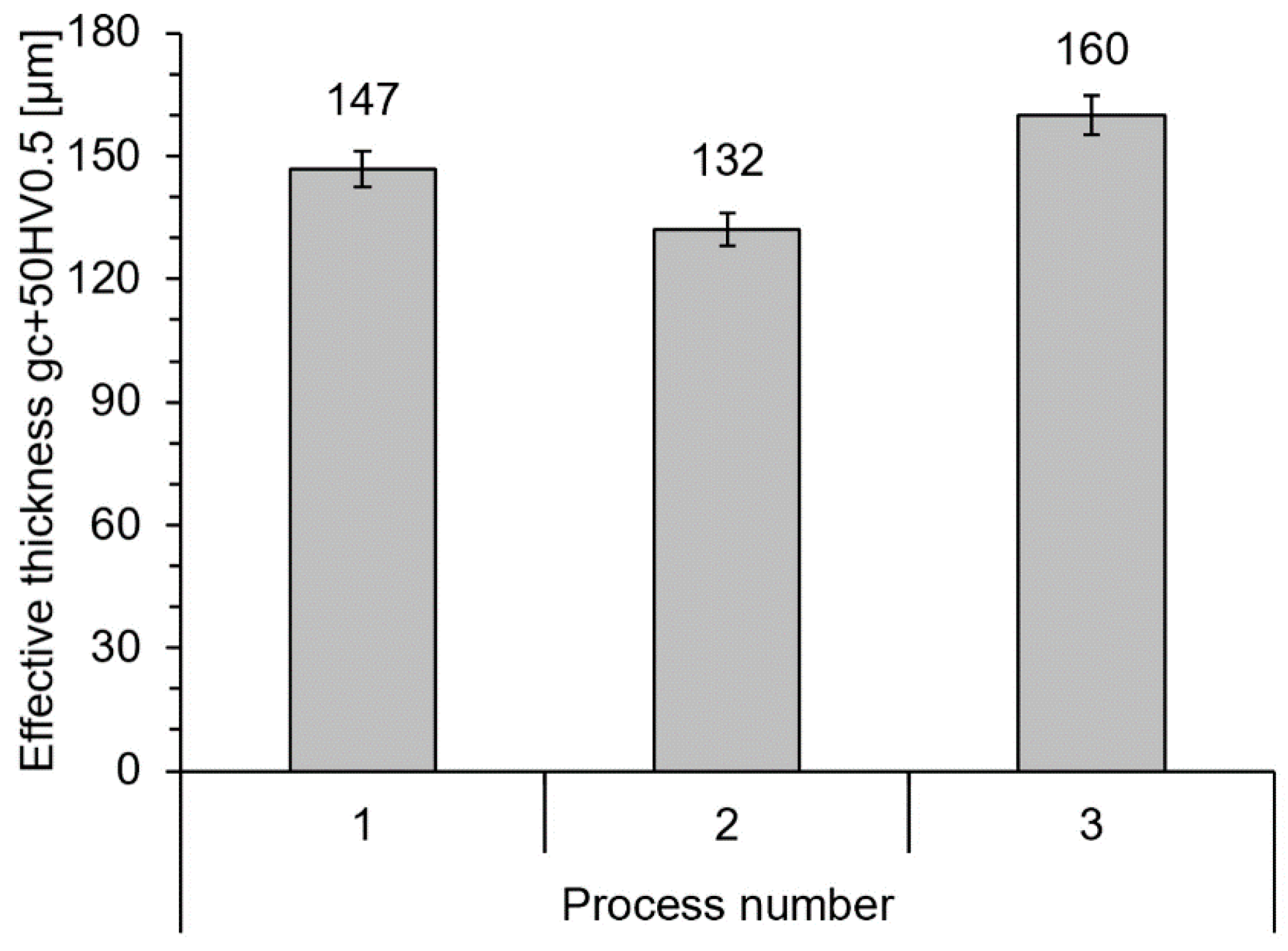
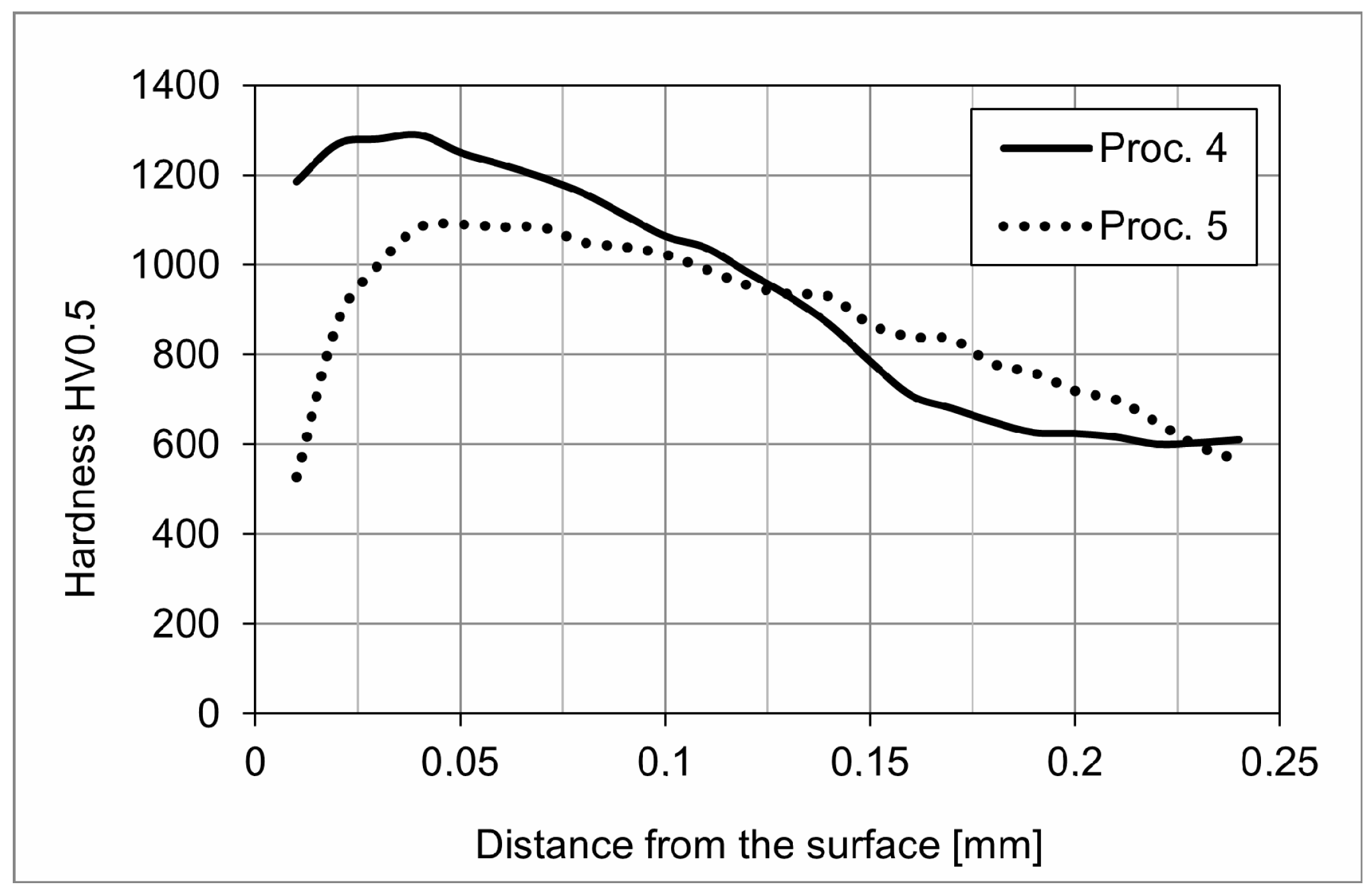
Figure 2, Figure 3, Figure 4 and Figure 5 show the results of the measurements of the iron nitride layer thickness (Figure 2), surface hardness (Figure 3) and effective diffusion zone thickness (Figure 4 and Figure 5) for processes 1–5.

3.1. Thickness of the Iron Nitride Layer

Process 1, which consisted of an ammonia saturation stage only, produced a nitrided layer with a 3 µm thick subsurface iron nitride layer (Figure 2). In process 2, with a vacuum annealing stage, the iron nitride layer that was formed in the saturation stage decomposed (Figure 2). At the annealing stage of process 3, the furnace retort was depressurised to 0.05 hPa and filled with nitrogen to a pressure of 1100 hPa (then, the stage proceeded without atmosphere flow). As a consequence, a nitrided layer with a 5 µm thick subsurface iron nitride layer was obtained (Figure 2). Process 4 (consisting of a 6 h saturation stage in an ammonia atmosphere only) produced an 11 µm thick iron nitride layer (Figure 2). After 6 h of vacuum annealing (process 5), the iron nitride layer formed in the saturation stage decomposed (Figure 2).

3.2. Hardness

The layer obtained in process 3 had a higher surface hardness than the layer obtained in process 1 (Figure 3). The surface hardness values for the nitrided layer were the lowest for process 2 (Figure 3-2). After 6 h of vacuum annealing, the surface hardness decreased from a value of 1057 HV10 to 831 HV10 (Figure 3). Process 4 produced an 11 µm thick iron nitride layer (Figure 2) and surface hardness of 1057 HV10 (Figure 3), thus higher than the hardness obtained in process 1 (Figure 2). It was also observed that the surface hardness obtained in process 5 (Figure 3) was comparable to that obtained in process 2 (Figure 3) (i.e., after 2 h of saturation and another 2 h of vacuum annealing). The hardness distributions illustrated in Figure 5 show that vacuum annealing resulted in a significant decrease in the hardness of the nitrided layer up to 80 µm from the surface. Above this distance, the hardness differences obtained in processes 4 and 5 were negligible.

3.3. Thickness of the Diffusion Layer (Solution)

The effective thickness of the diffusion layer obtained in process 3 (Figure 4) was slightly higher than that obtained in process 1 (Figure 4). The values of the effective thickness of the solution (diffusion) layer (Figure 4) were also the lowest for the layer nitrided in process 2.

3.4. Stresses

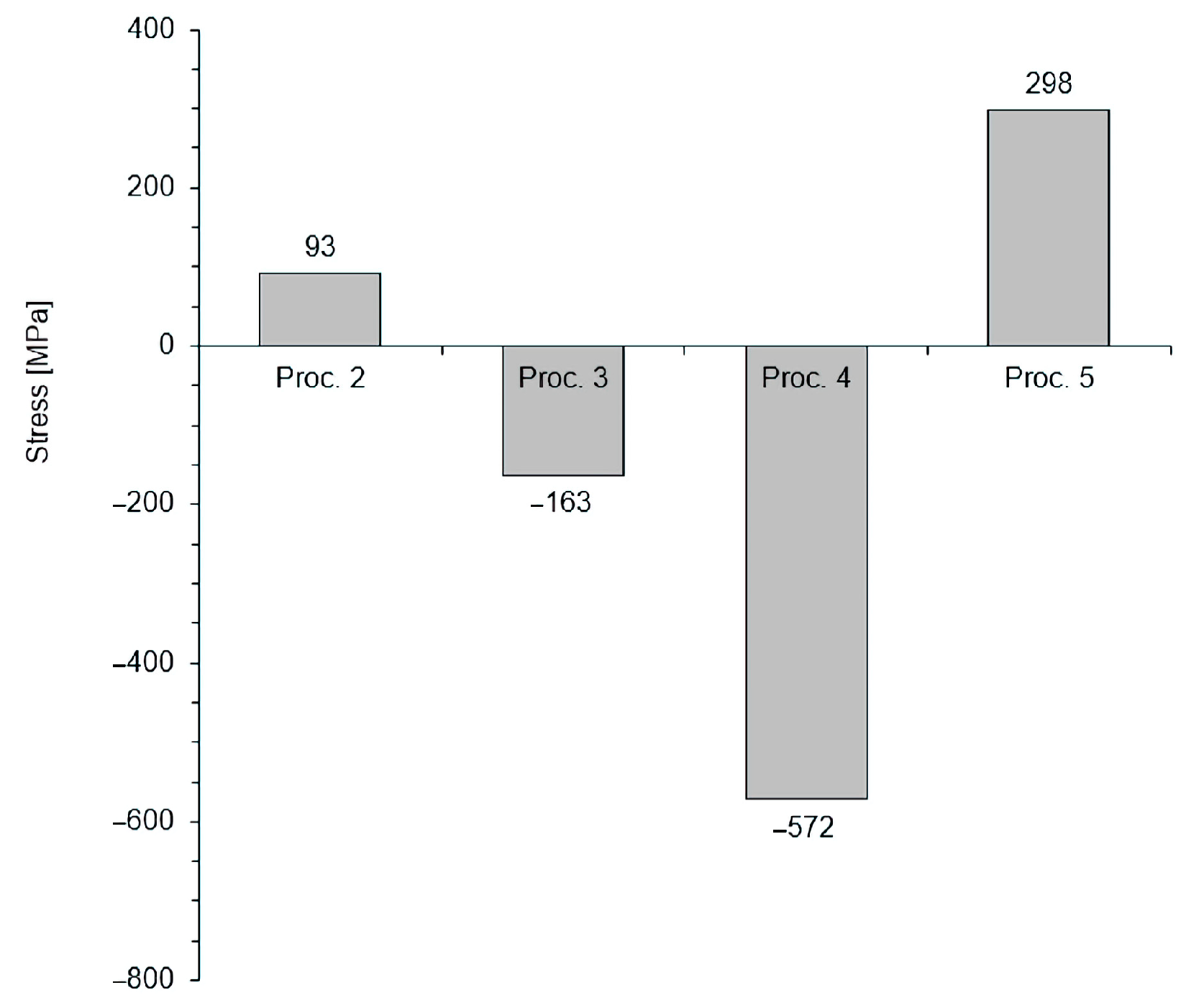
Figure 6 shows the values of tensile stresses in the subsurface zone of nitrided layers formed in processes 2, 3, 4 and 5. Nitrided layers without a subsurface layer of iron nitrides formed in processes 2 and 5 showed tensile stress values of 93 and 298 MPa, respectively. In contrast, nitrided layers with a subsurface layer of iron nitrides formed in processes 3 and 4 showed compressive stress values of −163 and −572 MPa, respectively.

4. Discussion

4.1. Formation of the Iron Nitride Layer

All of the described processes included a saturation step with a continuous flow of ammonia of 15 dm3/min at constant pressure, which ensured a constant value of nitriding potential [8]. Processes 1 and 4 produced nitrided layers with an effective internal nitriding zone thickness (gr+50) of 147 µm and 175 µm, respectively, and an iron nitride layer thickness of 3 µm and 11 µm, respectively. This implies that the thickness of the nitrided layer at the saturation stage depends only on the process time. This observation is consistent with the publication of M. Somers, who distinguishes between the following stages of nitrided layer formation: (1) nucleation of γ’ nitride on the nitrided surface and nucleation of ε nitride on top of the γ’ phase; (2) coalescence (merging) of biphasic nuclei and formation of a biphasic γ’/ε layer, which grows under the influence of nitrogen diffusion through the layer; (3) development of porosity in prolonged nitriding as a consequence of the inherent metastability of iron nitrides (under the pressure of 0.1 MPa in relation to Fe and N2). The associated formation of N2 molecules is first observed in the region with the highest nitrogen content (i.e., near the surface), where the most significant driving force for N2 development occurs. This is also the region that developed first and, therefore, existed the longest (hence increasing the probability of pore nucleation). Furthermore, pores develop first at energetically favourable nucleation sites, such as grain boundaries in the nitride layer. During continuous nitriding (or during holding), the pores merge and form pore channels that allow the gas mixture to reach inside the porous nitride layer [2].

4.2. Decomposition of the Iron Nitride Layer

Processes 2, 3 and 5 were two-step processes in which the partial pressure of ammonia was reduced to below 0.05 hPa during the second stage. At this pressure, the equilibrium of the iron nitride phases is no longer described by the Lehrer system but by the Fe-N equilibrium system [2]; therefore, at 560 °C, the iron nitrides are unstable and dissociate—and this process is irreversible [16]. Consequently, in processes 2 and 5, the iron nitride layer obtained in the saturation step decomposed (Figure 2), which resulted in a decrease in the surface hardness of the nitrided layer and the occurrence of tensile stresses in the subsurface zone of the nitrided layer (Figure 6). This mechanism can be supported by the mechanism mentioned in the previous section [2].

4.3. Development of the Solution Layer

The effective thicknesses of the nitrided layers in processes 1 and 2 differed slightly, proving that in process 2, during the annealing step of the nitrided layer in a vacuum, only iron nitride dissociation processes in the subsurface zone of the nitrided layer were effective.
As the thickness of the internal nitriding zone obtained in process 3 is slightly greater than the one obtained in process 1, this proves that the main driving force behind the increase in internal nitriding zone thickness is the relevant partial pressure of ammonia in the nitriding atmosphere and that the subsurface iron nitride layer is not a source of nitrogen for this zone (i.e., for the internal nitriding zone). The slight difference in the thicknesses (13 ± 14 µm) of the solution layers between processes 1 and 3 is likely due to the slow flattening of the nitrogen profile caused by the small concentration gradient within the diffusion layer. For process 2, it can be assumed that the sign of the concentration gradient direction was reversed, causing a slight loss of nitrogen from the layer.

4.4. Annealing in Inert Gas

The nitrided layer obtained in the two-stage process 3 differs fundamentally from the layers obtained in processes 2 and 5. This difference results from different conditions of the annealing stage in process 3. Samples in processes 2 and 5, after the stage of saturation in ammonia, were annealed in a vacuum below 0.05 hPa. The annealing stage in process 3 was carried out in an N2 atmosphere at a pressure of 1100 hPa (with a maximum NH3 partial pressure of 0.05 hPa) without atmosphere flow, i.e., in a closed system. Since such an ammonia pressure is probably too low to be the driving force of the growth of the iron nitride layer and the solution layer, the explanation must be sought elsewhere. Liapina et al. describe a ε + γ’ iron nitride layer built on an iron that during annealing integrates into a γ’ layer, with the thickness of the final γ’ phase being greater than the initial ε + γ’ [27,30,31,32]. The publications of Liapina et al. deal with long-term annealing of the nitrided layer at a temperature significantly lower than the nitriding temperature. It is reasonable to believe that at the nitriding temperature, the described phenomenon occurs faster and causes the transformation of the iron nitride layer ɛ + γ’ → γ’ and an increase in its overall thickness. As a consequence, the surface hardness increases (Figure 3); in this case, it is conducted in a manner that is comparably to the surface hardness of the nitrided layer obtained in the 6 h saturation process (process 4) (Figure 3 and Figure 4).

5. Conclusions

Based on the research carried out, the following conclusions were drawn:
  • In the process of low-pressure nitriding, the stability or decomposition of iron nitrides in the nitrided layer (during the annealing stage) depends on the partial pressure of ammonia in the annealing atmosphere. Lowering this pressure below a critical value (this value has not been defined mathematically in the literature so far) inhibits the growth of the internal nitriding zone thickness and initiates the decomposition of the iron nitride layer formed in the saturation stage.
  • The subsurface layer of iron nitrides is not a source of nitrogen for the internal nitriding zone.
  • Annealing of the nitrided layer being formed in an inert atmosphere inhibits the growth of the thickness of the iron nitride layer and the internal nitriding zone. Instead, the processes of transformation of the mixture of ε + γ’ phases to a uniform γ’ (ɛ + γ’ → γ’) phase and development of the nitrogen profile in the solution layer caused by the gradient of atomic nitrogen concentration within the solution layer occur in the layer.
  • Vacuum annealing during the low-pressure nitriding process leads to the decomposition of the iron nitride layer (formed during the saturation stage) and to unfavourable changes in the structure of the nitrided layer formed. This leads to a change in the type of stress from compressive to tensile and excludes their fitness for practical applications.

Author Contributions

Conceptualization, E.W.-K., J.M. and B.J.; Investigation, E.W.-K. and B.J.; Supervision, E.W.-K.; Writing—original draft, J.M.; Writing—review and editing, E.W.-K. All authors have read and agreed to the published version of the manuscript.

Funding

This research received no external funding.

Institutional Review Board Statement

Not applicable.

Informed Consent Statement

Not applicable.

Data Availability Statement

Data are contained within the article.

Conflicts of Interest

The authors declare that they have no conflict of interest and give their informed consent to the publication of the presented text. The funders had no role in the design of the study; in the collection, analyses, or interpretation of data; in the writing of the manuscript, or in the decision to publish the results. No experiments with humans or animals were conducted in the framework of the studies presented in the publication.

References

  1. Somers, M.; Mittemeijer, E. Layer-Growth Kinetics on Gaseous Nitriding of Pure Iron: Evaluation of Diffusion Coefficients for Nitrogen in Iron Nitrides. Metall. Mater. Trans. A 1995, 26, 57–74. [Google Scholar] [CrossRef]
  2. Somers, M. IFHTSE Global 21: Heat Treatment and Surface Engineering in the Twenty-First Century Part 14—Development of Compound Layer during Nitriding and Nitrocarburising; Current Understanding and Future Challenges. Int. Heat Treat. Surf. Eng. 2011, 5, 7–16. [Google Scholar] [CrossRef]
  3. Lehrer, E. Über das Eisen-Wasserstoff-Amoniak-Gleichgewicht. Z. Elektrochem. 1930, 36, 383–392. [Google Scholar]
  4. Kubaszewski, O. Iron-Binary Phase Diagrams; Springer: Berlin/Heidelberg, Germany, 1982. [Google Scholar]
  5. Michalski, J. Using Nitrogen Availability as a Nitriding Process Parameter. Ind. Heat. 2012, 10, 63–68. [Google Scholar]
  6. Ratajski, J. Wybrane Aspekty Współczesnego Azotowania Gazowego Pod Kątem Sterowania Procesem; Politechnika Koszalińska: Koszalin, Poland, 2003. [Google Scholar]
  7. Tacikowski, J.; Zyśk, J.; Sułkowski, I. Opracowanie Procesu Azotowania Stali Węglowych i Stopowych w Atmosferach Zmniejszających Zużycie Deficytowego Amoniaku; Project no 106.00.0051; Instytut Mechaniki Precyzyjnej: Warszawa, Poland, 1984. [Google Scholar]
  8. Michalski, J.; Burdyński, K.; Wach, P.; Łataś, Z. Nitrogen Availability of Nitriding Atmosphere in Controlled Gas Nitriding Processes. Arch. Metall. Mater. 2015, 60, 747–754. [Google Scholar] [CrossRef]
  9. Malkiewicz, T. Metaloznawstwo Stopów Żelaza; PWN: Warszawa, Poland, 1976. [Google Scholar]
  10. Fast, J.; Verrijp, M. Solubility of Nitrogen in Alpha-Iron. J. Iron Steel Inst. 1955, 180, 337–343. [Google Scholar]
  11. Rawling, R.; Hatherley, P. Iron-Manganese-Nitrogen Ferrite: The Activity of Nitrogen and Solubility of Manganese Nitrides. Met. Sci. 1973, 3, 97–103. [Google Scholar] [CrossRef]
  12. Grabke, H. Reaktionen von Ammoniak, Stickstoff und Wasserstoff an der Oberfläche von Eisen. Ber. Bunsenges. Phys. Chem. 1968, 4, 533–548. [Google Scholar]
  13. Smirnov, A.; Kuleshov, Y. Calculations for Nitriding with Diluted Ammonia. Met. Sci. Heat Treat. 1966, 8, 395–403. [Google Scholar] [CrossRef]
  14. Yurovskikh, A.; Kardonina, N.; Kolpakov, A. Phase Transformations in Nitrided Iron Powders. Met. Sci. Heat Treat. 2015, 57, 507–514. [Google Scholar] [CrossRef]
  15. Jentzsch, W.; Esser, F.; Bohmer, S. Mathematissches Modell Fur Die Nitrierung von Weicheinsen. Neue Hutte 1981, 1, 19–23. [Google Scholar]
  16. Kardonina, N.; Yurovskikh, A.; Kolpakov, A. Transformations in the Fe–N System. Met. Sci. Heat Treat. 2010, 52, 457–467. [Google Scholar] [CrossRef]
  17. Du Marchie van Voorthuysen, E.; Boerma, D.; Chechenin, N. Low-Temperature Extension of the Lehrer Diagram and the Iron-Nitrogen Phase Diagram. Metall. Mater. Trans. A 2002, 33, 2593–2598. [Google Scholar] [CrossRef]
  18. Lightfoot, B.; Jack, D. Kinetics of Nitriding with and without White Layer Formation. In Heat Treatment’73, Proceedings of a Conference Organized by the Heat Treatment Joint Committee of the Iron and Steel Institute, the Institute of Metals, and the Institution of Metallurgists, Held at the Portman Intercontinental Hotel, London, UK, 12–13 December 1973; The Metals Society: London, UK, 1975; pp. 59–66. [Google Scholar]
  19. Lakhtin, Y.; Kogan, Y.; Bulgach, A. Calculation of the Effect of Alloying, Elements on the Solubility and Diffusion of Nitrogen in Steel during the Nitriding o the Alpha and Gamma’ Phases. In TRUDY NAMI; Central Scientific Research Automobile and Automotive Engines Institute: Moscow, Russia, 1978; pp. 42–59. [Google Scholar]
  20. Schwerdtfeger, K.; Grieveson, P.; Turdogan, E. Growth Rate of Fe4N on Alpha. Trans. Metall. Soc. AIME 1969, 245, 2461–2466. [Google Scholar]
  21. Ratajski, J. Relation between Phase Composition of Compound Zone and Growth Kinetics of Diffusion Zone during Nitriding of Steel. Surf. Coat. Technol. 2009, 203, 2300–2306. [Google Scholar] [CrossRef]
  22. Ratajski, J. Matematyczne Modelowanie Procesu Azotowania Gazowego; Politechnika Koszalińska: Koszalin, Poland, 2011. [Google Scholar]
  23. Sugita, Y.; Takahashi, H.; Komuro, M. Magnetic and Mössbauer Studies of Single-crystal Fe16N2 and Fe-N Martensite Films Epitaxially Grown by Molecular Beam Epitaxy. J. Appl. Phys. 1994, 76, 6637–6641. [Google Scholar] [CrossRef]
  24. Kooi, B.; Somers, M.; Jutte, R.; Mittemeijer, E. On the Oxidation of α-Fe and ε-Fe2N1−z II. Residual Strains and Blisters in the Oxide Layer. Oxid. Met. 1997, 48, 111–128. [Google Scholar] [CrossRef] [Green Version]
  25. Wołowiec-Korecka, E.; Michalski, J.; Kucharska, B. Kinetic Aspects of Low-Pressure Nitriding Process. Vacuum 2018, 155, 292–299. [Google Scholar] [CrossRef]
  26. Frączek, T.; Michalski, J.; Kucharska, B.; Opydo, M.; Ogórek, M. Phase Transformations in the Nitrided Layer during Annealing under Reduced Pressure. Arch. Civ. Mech. Eng. 2021, 21, 48. [Google Scholar] [CrossRef]
  27. Liapina, T.; Leineweber, A.; Mittemeijer, E. Phase Transformations in Iron-Nitride Compound Layers upon Low-Temperature Annealing: Diffusion Kinetics of Nitrogen in ε- and Γ′-Iron Nitrides. Metall. Mater. Trans. A 2006, 37, 319–330. [Google Scholar] [CrossRef]
  28. Kula, P.; Wołowiec, E.; Pietrasik, R.; Dybowski, K.; Januszewicz, B. Non-Steady State Approach to the Vacuum Nitriding for Tools. Vacuum 2013, 88, 1–7. [Google Scholar] [CrossRef] [Green Version]
  29. Kula, P.; Pietrasik, R.; Stańczyk-Wołowiec, E. Method of Nitriding Tools Made of Iron. Alloys. Patent PL 219125, 2014. [Google Scholar]
  30. Liapina, T. Phase Transformations in Interstitial Fe-N Alloys. Ph.D. Thesis, Universitat Stuttgart, Stuttgart, Germany, 2005. [Google Scholar]
  31. Liapina, T.; Leineweber, A.; Mittemeijer, E. Nitrogen Redistribution in ε/Γ′-Iron Nitride Compound Layers upon Annealing. Scr. Mater. 2003, 48, 1643–1648. [Google Scholar] [CrossRef]
  32. Liapina, T.; Leineweber, A.; Mittemeijer, E. Phase Transformations in ε-/γ’-Iron Nitride Compound Layers in the Temperature Range of 613–693 K. Defect Diffus. Forum 2005, 237–240, 1147–1152. [Google Scholar] [CrossRef]
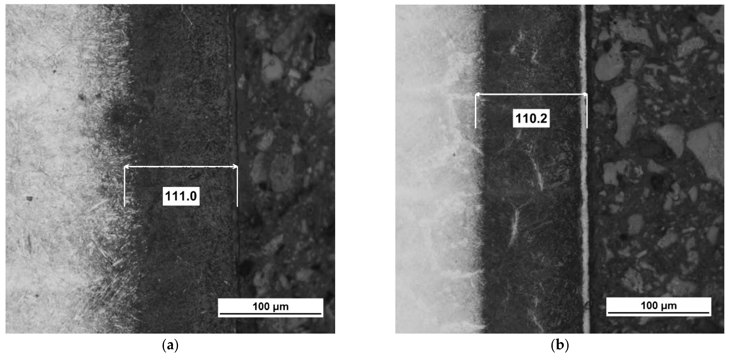
Figure 1. Microstructures of X37CrMoV5-1 steel after low-pressure nitriding processes: (a) process 2, (b) process 3, (c) process 4, (d) process 5.
Coatings 13 00257 g001aCoatings 13 00257 g001b
Figure 2. Results of thickness of the iron nitride layer analysis of X37CrMoV5-1 steel after low-pressure nitriding processes.
Coatings 13 00257 g002
Figure 3. Results of surface hardness analysis of X37CrMoV5-1 steel after low-pressure nitriding processes.
Coatings 13 00257 g003
Figure 4. Results of effective thickness (diffusion zone thickness) analysis of X37CrMoV5-1 steel after low-pressure nitriding processes.
Coatings 13 00257 g004
Figure 5. Results of hardness distribution in the nitrided layer analysis of X37CrMoV5-1 steel after low-pressure nitriding processes.
Coatings 13 00257 g005
Figure 6. Residual stresses in the subsurface zone of the nitrided layer obtained in X37CrMoV5-1 steel after low-pressure nitriding.
Coatings 13 00257 g006
Table 1. Chemical composition of X37CrMoV5-1 steel (% by weight).
CSiMnCrMoNiV
0.371.000.385.151.300.000.40
Table 2. Process parameters for low-pressure nitriding.
Process No.Saturation
Time/Atmosphere/Pressure (hPa)
Annealing
Time/Atmosphere/Pressure (hPa)
12 h/NH3/24None
22 h/NH3/242 h/vacuum/<0.05
32 h/NH3/242h/N2/1100
46 h/NH3/24None
56 h/NH3/246 h/vacuum/<0.05
Disclaimer/Publisher’s Note: The statements, opinions and data contained in all publications are solely those of the individual author(s) and contributor(s) and not of MDPI and/or the editor(s). MDPI and/or the editor(s) disclaim responsibility for any injury to people or property resulting from any ideas, methods, instructions or products referred to in the content.