Abstract
The azimuthal dependences of the optical second harmonic generation signal from crystallized regions (spherulites) of the ferroelectric phase in lead zirconate titanate films are investigated to determine the symmetry and orientation of crystallites. These dependencies in different regions of the same spherulite have different shapes, which indicates a difference in crystallographic orientations and/or symmetry. Based on the assumption of the possible presence of two syngonies and three orientations for each, the fitting of experimental azimuthal dependences by model curves was carried out, which provided information about the ratio of these phases and orientations in different areas of the film.
1. Introduction
Lead zirconate titanate (PZT) thin films are the subject of research and are widely used in nanocomposite structures [1] and flexible wearable electronics [2] in MEMS devices (sensors, actuators, energy storage devices) [3].
One of the determining parameters of crystals is their syngony and crystallographic orientation. The growth orientation determines the basic electrophysical properties of ferroelectrics [100], orientation of PZT grains corresponds to high piezoelectric properties. In [111], orientation leads to lower elastic stress, which is suitable for memory applications [5]. For some MEMS applications, textured films with a mixture of [100] and [111] orientations have the best energy conversion efficiency [6].
Conventional techniques to determine crystallographic parameters are based on X-ray diffraction [7] or electron diffraction [8]. However, for some materials, optical techniques are preferable, mostly due to their nondestructive and noninvasive nature. Recently, advanced polarization light microscopy (PLM) based on birefringence, including image processing algorithms [9,10], shows that PLM can significantly complement the information obtained by conventional techniques or even replace them. The contrast of the PLM images is provided by ordinary and extraordinary optical constants.
For decades, nonlinear optical microscopy, based on second harmonic generation (SHG), has been developing, and at present, it is considered a very effective technique for studing the crystallography of electronic materials, biological tissues, and ferroelectrics. Modern SHG microscopy is a polarization type of microscopy, and it allows the crystallographic structure of single crystalline, polycrystalline, and textured materials to be determined. The contrast of the SHG microscopy images is provided by nonlinear susceptibility tensor components. A detailed review of nonlinear optical microscopy can be found in [11]. In [12], a comparison of polarized and non-polarized SHG microscopy is presented. In [13], an open-source package called the Second Harmonic Analysis of Anisotropic Rotational Polarimetry was suggested for the analytical and numerical modeling of optical second harmonic generation in anisotropic crystals. In spite of these developments, SHG microscopy is not provided by established software, such as X-Ray diffractometers or electron microscopes. This is why most research requires custom image processing based on fundamental relations. This is also valid for the SHG microscopy of ferroelectrics, where domain structure [14,15,16] and crystalline phases and crystallite orientation [17,18,19,20,21] are studied.
In this paper, we study the local crystallographic structure of a rather complex system that is PZT polycrystalline spherulite-type films, which exhibit not only various crystallographic faces but various syngonies as well. Two experimental techniques were used: SHG microscopy and electron backscattered diffraction (EBSD). The influence of crystallization temperatures and the type of substrate on the microscopic structure of spherulites was analyzed. The capabilities of the two used methods for determining local syngonies and orientations of surface faces are discussed.
2. Materials and Methods
2.1. Sample
In the experiment, we used lead zirconate titanate films (PZT) with a zirconium/titanium atom ratio of 54/46 on platinized Glassceram (ST-50) and silicon (Si) substrates (“Union Partners”, Nizhny Novgorod, Russia). The films were fabricated by RF magnetron sputtering ("ONIKS", Izhevsk, Russia) followed by annealing [22]. Depending on the annealing temperature Tan, the film either consisted of separate perovskite spherulites embedded into the centrosymmetric pyrochlore phase (Tan = 550 °C) or was a continuous perovskite ferroelectric film formed by densely packed truncated spherulites (Tan = 580 °C). The thickness of the films was 300 nm. Here, we study in detail PZT/ST-50550, PZT/Si550, and PZT/Si580 samples (the subscripts correspond to the annealing temperature). Previous studies [23] showed that spherulites consist of nanocrystals of monoclinic (m) and tetragonal (4 mm) phases with three crystallographic orientations, which are [100], [110], and [111]. The use of two types of substrates was determined by the difference in the nature of two-dimensional mechanical stresses acting on the film. In the case of Glassceram, compression stress acted on the film, while in the case of silicon, tension stress acted on the film [24]. This allowed us to investigate the influence of such stresses and is a common topic of research [25].
2.2. SHG Microscopy
The experimental setup (Figure 1) consisted of a confocal optical microscope (WITec alpha-300, Ulm, Germany) with a pulsed laser radiation source with a wavelength of 800 nm, a pulse duration of 100 fs, and a repetition rate of 80 MHz. The laser beam was focused on the sample at a normal incidence and was reflected together with the optical second harmonic (SH) at 400 nm. The focusing area has a lateral size of about 1 μm. As films are thin, the entire depth of the film was irradiated. The reflected radiation was collected with the same objective. A half-wave plate was used to rotate the polarization of the input beam. A polaroid was used as the analyzer. The reflected fundamental radiation was cut off by the color broadband and narrowband filters. Then, the SH radiation was delivered to the photomultiplier tube. At a normal incidence, the simultaneous rotation of the half-wave plate and analyzer was equal to rotating the sample. In both cases, the dependence of SHG intensity on the azimuthal angle φ was measured; the latter is called azimuthal dependence. In our experiments, azimuthal dependencies of SHG intensity were measured for different positions of the laser spot on the sample surface (see Figure 2a, blue spots). In total, 72 azimuthal dependencies were measured for each spherulite. SHG images (2D surface scans) were obtained with a fixed polarization of both the input pump (800 nm) and detected SHG (400 nm), which were parallel to each other and φ = 0.
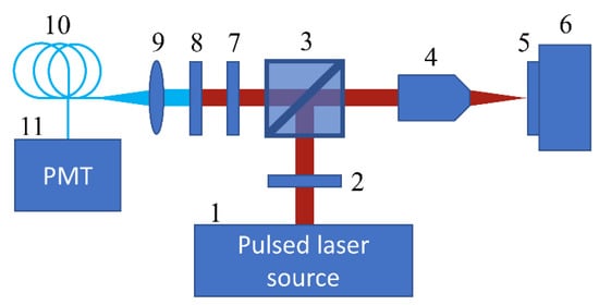
Figure 1.
Scheme of experimental setup. 1—laser source, 2—half-wave plate, 3—beam splitter, 4—objective lens, 5—sample, 6—scanning stage, 7—polaroid (analyzer), 8—color filters, 9—lens, 10—optical fiber, 11—photomultiplier tube.

Figure 2.
PZT/ST-50550: (a)—Nonlinear optical microscopic image of a spherulite at a specified angle of polarizer and analyzer. The blue dots show the measured areas of the azimuthal dependencies. In the following, these spots are denoted by their polar coordinate according to the figure. (b)—Relative volume of each syngony/orientation depending on the polar coordinate of the region under study. (c)—Relative volume of tetragonal and monoclinic phases (contributions of orientations are summed) depending on the polar coordinate of the region under study. Glassceram substrate.
2.3. Modeling the SHG Intensity
For ferroelectrics, the SHG wave electric field , pumped by a laser wave electric field , was proportional to the dielectric polarization , that is, the dipole moment per unit volume [26].
where all fields are taken in a crystallographic frame and and are nonlinear susceptibility tensors of the second and third order in the crystallographic frame. Nonzero tensor components in the crystallographic frame can be found in [27]. The measured SHG intensity is proportional to the field squared.
For a nanocrystalline ferroelectric, polarization is formed by crystallites consisting of domains. For a crystallite, it can be written as , where and —is a number of 180° pairs of the i domain fraction (i can vary between one and three) within a nanocrystalline. The scanning SHG microscopy of a ferroelectric thin film with a spot diameter of 1 µm does not allow the spatial resolution of either domains or nanocrystals. Then, SHG probes the polarization averaged over the spot, which is , where Aj determines the relative volume of each of six phases within the laser spot: two syngonies, monoclinic m and tetragonal 4 mm, with three crystallographic orientations. Obviously, . Equation (1) has to be applied to each nanocrystal .
In order to write the equation for the measured SHG intensity, a transformation of Equation (1) from the crystallographic frame to the laboratory frame has to be performed, and the fields have to be written outside the crystal.
Generally, the fundamental wave field vector with the amplitude of falling on the sample can be written as:
where , , and are the Fresnel coefficients for the fundamental wavelength, θ = 0 is the angle of incidence, φ is the azimuthal angle, and is the amplitude of the fundamental wave. This produces the equation:
Then, for the SHG field with the amplitude of emerging from the crystal, the following equation is given:
Transformations from the laboratory to crystallographic frame for fundamental waves and back from the crystallographic to laboratory frame for SH waves are described by the Euler matrices:
Matrix Turn1 depends on the crystallographic orientation:
Matrix Turn2 describes the sample rotation around the normal to its surface (or, in our experiments, the identical operation of simultaneous rotation of fundamental and SH wave polarization).
In linear optics, for the isotropic nonabsorbing medium, Fresnel factors at a normal incidence are expressed as:
For the modeling of SHG, only nonzero second-order tensor components are taken into account, which are:
for the tetragonal symmetry:
for the monoclinic symmetry:
For each nanocrystal, we obtained:
This provides the following equation for the SH field generated by nanocrystalline ferroelectric:
Equation (13) is used for fitting the experimental data. The fitting parameters are the phase fractions Aj (five parameters, taking into account that ∑Aj = 1) and the tensor components are normalized on of the monoclinic phase (12 parameters). In the fitting procedure for each spherulite, 72 azimuthal dependences were considered for 72 different spots, in which nonlinear susceptibilities were kept the same for the whole spherulite, while the phase fractions were different fitting parameters for each spot of the shperulite. For the fitting procedure, the Wolfram research package was used.
2.4. Electron Backscattered Diffraction (EBSD)
This method is based on the analysis of Kikuchi diffraction patterns of electrons scattered from crystallographic planes of a tilted sample. The EBSD method allows local information on the rotation of planes and crystallographic directions to be obtained at any point of the crystal relative to external macroscopic coordinates. By scanning the surface of a sample with a focused electron beam with the accompanying obtaining, fixing, and decoding of diffraction patterns, it is possible to make maps of crystallographic orientations and their subsequent analysis.
3. Results
3.1. SHG Microscopy
Figure 2a shows the nonlinear optical (SHG) image of the spherulitic structure for PZT/ST-50550. The spherulite is not a single crystal but consists of crystallites of a perovskite structure, which give a high SHG signal (Figure 2). The surrounding regions consist of a centrosymmetric paraelectric phase, which, due to a nonpolarized lattice, cannot be a source of SHG.
The azimuthal dependencies of the SHG were measured for a series of regions for each investigated spherulite. These areas were located on a circle of a smaller diameter than the spherulite itself (Figure 2a). For joint polygon-shaped spherulites, the diameter of this circle was chosen so that it completely fell on one spherulite. For each spherulite, 72 areas evenly distributed on the circle were investigated, i.e., local areas on the circle were separated from each other by five degrees. The distance between adjacent points ranged from 0.5 to 1 micron, depending on the chosen radius of the circle.
The structure of the samples on the silicon substrate (Figure 3a,b) did not visually differ from the films on the Glassceram substrate (Figure 2a).
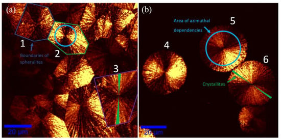
Figure 3.
Surface image (SHG) for samples on silicon with joint spherulites PZT/Si580 (a) and with separate spherulites PZT/Si550 (b). The colored polygons on left image show boundaries between spherulites. Examples of circles where the local areas under study were located are shown on spherulites with numbers 2 and 5 (on other spherulites they are the same). Supposed shape of crystallites that grew to either side of the center is shown on spherulites numbered 3 and 6.
The azimuthal dependencies of SHG had a six-petal shape with different intensities of pairs for opposite petals (Figure 3). In different regions, the shape of the dependencies was diverse (various ratios of petal intensities). Such behavior suggests that spherulite consists of multiple crystallites of several coexisting phases that have different symmetry and orientations. In different regions of the spherulite, the ratio of these phases changes, which leads to a difference in the azimuthal dependence. These experimental dependencies were fitted by a single formula (Equation (13)), which gave 13 nonlinear susceptibility tensor components and six weight coefficients for six phases. The fitting curves correspond quite well to the experimental azimuthal dependencies of the SHG intensity (Figure 4).

Figure 4.
Azimuthal dependencies of the SHG intensity in different areas of the spherulite (polar coordinate of the area: (a)—0°, (b)—40°, (c)—80°, (d)—120°, (e)—160°, (f)—200°, (g)—240°, (h)—280°). The dots show the experimental data, the lines show the fitting. (i)—Sets of experimental azimuthal dependences of four different spherulites. Each set consists of 72 azimuthal dependences, which correspond to 72 areas of one spherulite, located on one circle as showed in Figure 3. Silicon substrate.
From the best fit of azimuthal dependences, we obtained the following relative values of nonlinear tensor susceptibilities:
If we sum up the contributions of the three orientations of each syngony, it appears that the distribution of tetragonal and monoclinic phases in some spherulites is fairly uniform (Figure 2c). The average amount of the tetragonal phase is about 60%, and the monoclinic phase is—40%. The average proportion of orientations in the studied areas according to SHG measurements and analytical interpretation is: [100]—44%, [110]—29%, and [111]—27%. Such spherulitic structures in the PZT have a less dense, weakly oriented phase at the edges and a denser phase with a significant <110> texture in the center [22]. In our experiment, the investigated regions were apparently in the weakly oriented perovskite phase.
Different spherulites showed varying sets of azimuthal dependences from local regions (Figure 4). This suggests that the crystallographic or orientational composition of the crystallites varied for each spherulite. It can be also seen on the SHG maps (Figure 3). One SHG map corresponds to specific fixed angles of in/out light polarization, and in these conditions, spherulites still look different, which is related to their structure.
The SHG azimuthal fitting calculations showed that, on average, there was a lower monoclinic phase in spherulites on silicon (as well as on Glassceram) than in the tetragonal phase (Figure 5).
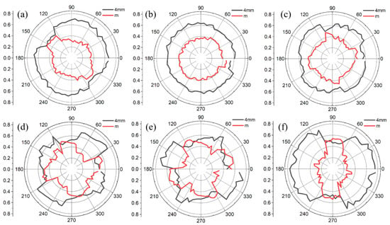
In all the investigated spherulites (including joint ones) in samples on the silicon substrate, unlike samples on Glassceram, there was a complete coincidence of the shape of azimuthal dependences for the opposite regions on the spherulite, the polar coordinate of which differed by 180° (Figure 6). These dependencies sometimes differed insignificantly, including the signal amplitude, but this could be explained by the inaccuracy of the beam hitting a specific region of the sample, as well as by the influence of small differences in focusing. Since the shape of the azimuthal dependence depends on the specific crystallographic parameters in this region, it seems that the opposite regions of spherulites in these samples have identical orientation and syngony. In this regard, the dependencies shown in Figure 5 are centrosymmetric. In the sample on a Glassceram substrate, such a pattern was not observed; the shape of the azimuthal dependences of the SHG from the opposite regions was different. This means that the orientation and/or syngony of the opposite regions in spherulites on Glassceram are different.

Figure 6.
Experimental azimuthal dependencies of the SHG intensity in the regions of spherulite number six, the polar coordinate of which differs by 180° (In one row (a–e) five random different regions on the spherulite, in the second row (f–j) the corresponding opposite regions). The image on the right illustrates the location of the local regions. Silicon substrate.
The intensities of the second harmonic from the PZT films were compared with the reference sample of z-cut quartz. Considering normalization to the incident radiation intensity, we can estimate that the effective component of the nonlinear susceptibility of the PZT films is 180 times greater than that of quartz, which correlates with the literature data. A 30-degree temperature difference between two samples can affect the growth rate and filling factor (continuous film or separate islands), but it seems that it is not enough to significantly change the phase composition. Orientation distribution slightly differs for each spherulite, even on the same sample, but there are no significant correlations due to temperature change.
3.2. Electron Backscattered Diffraction (EBSD)
The same spherulite on the sample of the Glassceram substrate that was measured by SHG (Figure 2a) was investigated also by EBSD.
The representation of the whole set of crystal lattice orientations within the studied area can be in the form of traditional straight pole figures showing the projection of intersection points of different crystallographic directions with an upper hemisphere of arbitrary radius in the center of which the studied crystallographic basis is located.
The straight pole figures for all directions show homogeneous diffuse spots filled uniformly inside the bounding contours (Figure 7). This feature suggests the existence of a “continuous” smooth distortion of the crystal lattice of the perovskite island. The diameter of the spots reflects the magnitude of misorientations found within the studied area. Comparing the size of the spots with the distance from the center of the circle to the edge provides an estimate of the misorientation achieved at the site (a given perovskite island) of about 30 degrees.
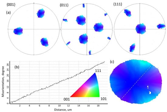
Figure 7.
(a) Straight pole figures (SPF) for {001}, {011}, and {111} directions, colored in IPF Z colors. Colored according to the coincidence of directions on the inverse pole figure (IPF) for the macroscopic Z-axis of the sample with the color-coding triangle. It allows matching the set of direction outputs (orientation) of the crystal lattice with its position on the IPF Z map of the investigated area. (b) Cell misorientation dependence on the distance from the center of spherulite (corresponds to dashed line on c). (c) Spherulite with the color palette corresponds to the z orientation. Glassceram substrate.
The observed distortions of the crystal lattice realized during the growth of islands of the perovskite phase are apparently a consequence of stresses arising in the film plane during the phase transition due to the difference in the specific volumes of the phases and/or the difference in their coefficient of thermal expansion when cooling them to room temperature.
Unfortunately, the attempt to resolve diffraction patterns using tetragonal, monoclinic, and rhombohedral symmetries was unsuccessful due to the proximity of the parameters of these phases to each other. So, the diffraction patterns were resolved using cubic symmetry.
It is shown that along all radial directions, there is a uniform change of cell orientation at a rate of 1.5 degrees per micron (Figure 7).
The average grain orientation is located in the center of the spherulite (it is the [111] orientation), which indicates a quasi-uniform distortion of the lattice in all directions during growth.
Cell orientation is rotated around the axis, which lies in the surface plane and is perpendicular to the radial direction (Figure 8b).
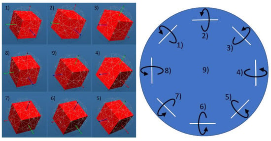
Figure 8.
Schematic view of orientation rotation. Circle here represents a spherulite. Orientation in the center of it (point 9) is [111]. This orientation is shown on left panel. To the sides (1,2,3…) it rotates around the axes that are shown as white lines. Glassceram substrate.
The fact that we observed different azimuthal dependencies of SHG from opposite regions on the spherulite of Glassceram was proven by the EBSD method. Though we cannot prove the symmetry, we know that the orientation of opposite regions is different (by 25–30 degrees in our case). There are a number of studies that show and discuss the rotation of cell orientation with the distance from the center of spherulite [28,29].
The modeling of the SHG response showed that the actual behavior of cell orientation/cell parameters could be more complicated than just rotation around one axis for each radial direction.
The comparison of SHG microscopy and EBSD reveals the following: Glassceram substrate orientation and symmetry distributions on spherulite were not symmetrically relative to the center (Figure 2b,c) in contrast to those on the silicon substrate (Figure 5). It can be clearly seen on the pole figure (Figure 7c) that opposite regions of spherulite on Glassceram that are located on other sides of the diameter have different orientations. In this regard, SHG PLM and XRD results prove each other.
4. Conclusions
Our research shows the capabilities of SHG microscopy to study the local crystallographic structure of PZT ferroelectric films and obtain the maps of the fraction of different syngonies and crystallographic phases. Our method is based on the measurements followed by fitting full-angle azimuthal (polarization) dependencies of SHG intensity for each chosen spot of the film. In spite of a large number of fitting parameters, they can be resolved with several operations. Firstly, the fitting parameters are separated into two groups: the first group consists of parameters which are equal for all spots measured (nonlinear susceptibility tensor components), while the second group consists of parameters that are unique for each spot measured (fractions of crystallites of different orientations and syngonies). We showed that SHG microscopy allowed us to distinguish between different syngonies, which are even close to the cubic one. At the same time, the EBSD method is not capable of that.
Based on the presented techniques, we can conclude that the main features of growth on PZT thin films are a nearly uniform mixture of tetragonal and monoclinic phases, whose composition corresponds to the morphotropic phase boundary. Tensile or compressive stresses acting on PZT films from the side of silicon or Glassceram substrates do not practically influence the phase mixture.
The substrate affects orientation distribution, which was proven both by SHG microscopy and EBSD. A slight non-uniform distribution of orientations, especially of the tetragonal phase, correlates with radial misorientation in perovskite spherulites.
Author Contributions
Conceptualization, I.P.P. and E.D.M.; Data curation, A.S.E. and M.V.S.; Formal analysis, A.S.E., M.V.S., I.P.P., S.V.S., and E.D.M.; Investigation, A.S.E., M.V.S., and S.V.S.; Methodology, I.P.P. and E.D.M.; Software, A.S.E. and E.D.M.; Validation, A.S.E., M.V.S., I.P.P., S.V.S., and E.D.M.; Writing—original draft, A.S.E., M.V.S., and S.V.S.; Writing—review and editing, I.P.P. and E.D.M. All authors have read and agreed to the published version of the manuscript.
Funding
The work was supported by the Russian Science Foundation (Grant # 22-12-00334), Ministry of Science and Education (Project No. 075-15-2022-1131). The work was performed using the equipment of the Center for Collective Use of RTU MIREA (Agreement No. 075-15-2021-689 with the Ministry of Education and Science). Experimental studies were carried out on the equipment of the Core shared research facilities “Composition, structure and properties of structural and functional materials” of the NRC «Kurchatov Institute»—CRISM “Prometey”.
Informed Consent Statement
Not applicable.
Data Availability Statement
Not applicable.
Conflicts of Interest
The authors declare no conflict of interest. The funders had no role in the design of the study; in the collection, analyses, or interpretation of data; in the writing of the manuscript; or in the decision to publish the results.
References
- Jian, L.; Kumar, A.S.; Lekha, C.C.; Vivek, S.; Salvado, I.; Kholkin, A.L.; Nair, S.S. Strong sub-resonance magnetoelectric coupling in PZT-NiFe2O4-PZT thin film composite. Nano-Struct. Nano-Objects 2019, 18, 100272. [Google Scholar] [CrossRef]
- Zhang, S.; Zhang, L.; Wang, L.; Wang, F.; Pan, G. A Flexible e-skin based on micro-structured PZT thin films prepared via a low-temperature PLD method. J. Mater. Chem. C 2019, 7, 4760–4769. [Google Scholar] [CrossRef]
- Muralt, P.; Polcawich, R.G.; Trolier-McKinstry, S. Piezoelectric thin films for sensors, actuators, and energy harvesting. MRS Bull. 2009, 34, 658–664. [Google Scholar] [CrossRef]
- Oikawa, T.; Aratani, M.; Funukubo, H.; Saito, K.; Mizuhira, M. Composition and orientation dependence of electrical properties of epitaxial Pb(Zr1-xTix)O3 thin films grown using metalorganic chemical vapor deposition. J. Appl. Phys. 2004, 95, 3111–3115. [Google Scholar] [CrossRef]
- Izyumskaya, N.; Alivov, Y.I.; Cho, S.J.; Morkoç, H.; Lee, H.; Kang, Y.S. Processing, structure, properties, and applications of PZT thin films. Crit. Rev. Solid State Mater. Sci. 2007, 32, 111–202. [Google Scholar] [CrossRef]
- Yamashita, K.; Nakajima, S.; Shiomi, J.; Noda, M.; Muralt, P. Vibrating Piezoelectric Energy Conversion Efficiency of Sol-Gel PZT Films with Various Crystal Orientations on MEMS Buckled Diaphragm Structures. In Proceedings of the 2019 IEEE International Symposium on Applications of Ferroelectrics (ISAF), Lausanne, Switzerland, 14–19 July 2019. [Google Scholar] [CrossRef]
- Tan, G.; Maruyama, K.; Kanamitsu, Y.; Nishioka, S.; Ozaki, T.; Umegaki, T.; Hida, H.; Kanno, I. Crystallographic contributions to piezoelectric properties in PZT thin films. Sci. Rep. 2019, 9, 7309. [Google Scholar] [CrossRef]
- Kolosov, V.Y.; Zhigalina, O.M.; Khmelenin, D.N.; Bokuniaeva, A.O. Crystal lattice orientation analysis of PZT thin film with 10% La content by transmission electron microscopy. AIP Conf. Proc. 2018, 2015, 020043. [Google Scholar] [CrossRef]
- Fan, J.; Lu, X.; Cao, W. Computer-aided characterization of ferroelectric phase transitions and domain structures using polarizing light microscopy. Appl. Phys. Lett. 2022, 120, 072902. [Google Scholar] [CrossRef]
- Qiu, C.; Wang, B.; Zhang, N.; Zhang, S.; Liu, J.; Walker, D.; Wang, Y.; Tian, H.; Shrout, T.R.; Xu, Z.; et al. Transparent ferroelectric crystals with ultrahigh piezoelectricity. Nature 2020, 577, 350–354. [Google Scholar] [CrossRef]
- Mazumder, N.; Balla, N.K.; Zhuo, G.Y.; Kistenev, Y.V.; Kumar, R.; Kao, F.J.; Brasselet, S.; Nikolaev, V.V.; Krivova, N.A. Label-free non-linear multimodal optical microscopy—Basics, development, and applications. Front. Phys. 2019, 7, 170. [Google Scholar] [CrossRef]
- Maragkakis, G.M.; Psilodimitrakopoulos, S.; Mouchliadis, L.; Paradisanos, I.; Lemonis, A.; Kioseoglou, G.; Stratakis, E. Imaging the crystal orientation of 2D transition metal dichalcogenides using polarization-resolved second-harmonic generation. Opto-Electron. Adv. 2019, 2, 190026-1–190026-8. [Google Scholar] [CrossRef]
- Zu, R.; Wang, B.; He, J.; Wang, J.J.; Weber, L.; Chen, L.Q.; Gopalan, V. Analytical and numerical modeling of optical second harmonic generation in anisotropic crystals using♯ SHAARP package. Npj Comput. Mater. 2022, 8, 246. [Google Scholar] [CrossRef]
- Zhang, Y.; Zhang, Y.; Guo, Q.; Zhong, X.; Chu, Y.; Lu, H.; Zhong, G.; Jiang, J.; Tan, C.; Liao, M.; et al. Characterization of domain distributions by second harmonic generation in ferroelectrics. Npj Comput. Mater. 2018, 4, 39. [Google Scholar] [CrossRef]
- Cherifi-Hertel, S.; Bulou, H.; Hertel, R.; Taupier, G.; Dorkenoo KD, H.; Andreas, C.; Guyonnet, J.; Gaponenko, I.; Gallo, K.; Paruch, P. Non-Ising and chiral ferroelectric domain walls revealed by nonlinear optical microscopy. Nat. Commun. 2017, 8, 15768. [Google Scholar] [CrossRef]
- Garcia, J.E.; Perez, R.; Ochoa, D.A.; Albareda, A.; Lente, M.H.; Eiras, J.A. Evaluation of domain wall motion in lead zirconate titanate ceramics by nonlinear response measurements. J. Appl. Phys. 2008, 103, 054108. [Google Scholar] [CrossRef]
- Kim, E.; Steinbrück, A.; Buscaglia, M.T.; Buscaglia, V.; Pertsch, T.; Grange, R. Second-harmonic generation of single BaTiO3 nanoparticles down to 22 nm diameter. ACS Nano 2013, 7, 5343–5349. [Google Scholar] [CrossRef]
- Li, C.; Wang, X.; Wu, Y.; Liang, F.; Wang, F.; Zhao, X.; Yu, H.; Zhang, H. Three-dimensional nonlinear photonic crystal in naturally grown potassium–tantalate–niobate perovskite ferroelectrics. Light Sci. Appl. 2020, 9, 193. [Google Scholar] [CrossRef]
- Wang, J.S.; Jin, K.J.; Gu, J.X.; Wan, Q.; Yao, H.B.; Yang, G.Z. Direct evidence of correlation between the second harmonic generation anisotropy patterns and the polarization orientation of perovskite ferroelectric. Sci. Rep. 2017, 7, 9051. [Google Scholar] [CrossRef]
- Strkalj, N.; Bortis, A.; Campanini, M.; Rossell, M.D.; Fiebig, M.; Trassin, M. Optical second harmonic signature of phase coexistence in ferroelectric| dielectric heterostructures. Phys. Rev. B 2022, 105, 174101. [Google Scholar] [CrossRef]
- Sherstyuk, N.E.; Mishina, E.D.; Lavrov, S.D.; Buryakov, A.M.; Marchenkova, M.A.; Elshin, A.S.; Sigov, A.S. Optical second harmonic generation microscopy for ferroic materials. Ferroelectrics 2015, 477, 29–46. [Google Scholar] [CrossRef]
- Pronin, I.P.; Kaptelov, E.Y.; Senkevich, S.V.; Klimov, V.A.; Zaĭtseva, N.V.; Shaplygina, T.A.; Pronin, V.P.; Kukushkin, S.A. Crystallization of thin polycrystalline PZT films on Si/SiO2/Pt substrates. Phys. Solid State 2010, 52, 132–136. [Google Scholar] [CrossRef]
- Pronin, V.P.; Dolgintsev, D.M.; Osipov, V.V.; Pronin, I.P.; Senkevich, S.V.; Kaptelov, E.Y. The change in the phase state of thin PZT layers in the region of the morphotropic phase boundary obtained by the RF magnetron sputtering with varying target-substrate distance. IOP Conf. Ser. MSandE 2018, 387, 012063. [Google Scholar] [CrossRef]
- Valeeva, A.R.; Kaptelov, E.Y.; Pronin, I.P.; Senkevich, S.V.; Pronin, V.P. Mechanical stresses in lead zirconate titanate thin films formed on substrates differing in temperature coefficients of linear expansion. Phys. Complex Syst. 2022, 3, 159–166. [Google Scholar] [CrossRef]
- Degheidy, A.R.; Elkenany, E.B. Impact of temperature and pressure on mechanical properties of GaxIn1− xAsyP1− y alloy lattice matched to different substrates. J. Alloys Compd. 2015, 652, 379–385. [Google Scholar] [CrossRef]
- Dolino, G.; Lajzerowicz, J.; Vallade, M. Second-harmonic light scattering by domains in ferroelectric triglycine sulfate. Phys. Rev. B 1970, 2, 2194. [Google Scholar] [CrossRef]
- Birss, R.R. Symmetry and Magnetism, 2nd ed.; North-Holland Publisher Company: Amsterdam, The Netherlands, 1966. [Google Scholar]
- Musterman, E.J.; Dierolf, V.; Jain, H. Curved lattices of crystals formed in glass. Int. J. Appl. Glass Sci. 2022, 13, 402–419. [Google Scholar] [CrossRef]
- Lutjes, N.R.; Zhou, S.; Antoja-Lleonart, J.; Noheda, B.; Ocelík, V. Spherulitic and rotational crystal growth of Quartz thin films. Sci. Rep. 2021, 11, 14888. [Google Scholar] [CrossRef]
Disclaimer/Publisher’s Note: The statements, opinions and data contained in all publications are solely those of the individual author(s) and contributor(s) and not of MDPI and/or the editor(s). MDPI and/or the editor(s) disclaim responsibility for any injury to people or property resulting from any ideas, methods, instructions or products referred to in the content. |
© 2023 by the authors. Licensee MDPI, Basel, Switzerland. This article is an open access article distributed under the terms and conditions of the Creative Commons Attribution (CC BY) license (https://creativecommons.org/licenses/by/4.0/).