Article

Enhanced Corrosion Resistance of TiZrN-Coated Additively Manufactured 8620 Low-Alloy Steel in Nitrate Salt Solution and Salt Bath

School of Engineering and Technology, Central Michigan University, Mount Pleasant, MI 48859, USA
*
Author to whom correspondence should be addressed.
Coatings 2023, 13(12), 1998; https://doi.org/10.3390/coatings13121998
Submission received: 25 October 2023 / Revised: 21 November 2023 / Accepted: 22 November 2023 / Published: 24 November 2023

Abstract

:
In this study, corrosion resistance of TiZrN-coated additively manufactured (3D-printed) 8620 steel has been separately studied in a 60–40 wt% NaNO3 + KNO3 molten salt and in an aqueous nitrate salt environment. Microstructural characterization of the as-built bare 3D-printed 8620 sample revealed martensitic microstructures. High-temperature corrosion analysis in molten nitrate salt revealed improved film stability and corrosion resistance of the coating. The coated 3D-printed sample showed no scale of corrosion products, whereas the bare 3D-printed sample exhibited a layer of corrosion products of 2.62 ± 0.24 µm thickness. Potentiodynamic polarization and electrochemical impedance spectroscopy tests in aqueous nitrate salts at room temperature exhibited an ~8-fold decrease in corrosion current density and a ~7-fold increase in charge transfer resistance, indicating enhanced corrosion resistance of the coated 8620. The coated wrought 8620 showed comparable corrosion resistance to that of the coated 3D-printed sample. However, in aqueous solution, the bare 3D-printed sample exhibited localized corrosion, whereas the bare wrought revealed uniform corrosion on the surface.

1. Introduction

To curb the global average temperature rise, caused by the increased usage of fossil fuel-based energy sources, e.g., coal, oil, and natural gas, incorporation of renewable energy sources in the global energy supply has been on the rise [1]. Solar energy can play an important role in continuing this effort. At present, two technologies are in use to harvest solar energy: photovoltaics (PV) and concentrated solar power (CSP). PV technology turns solar radiation directly into electricity, while CSP technology concentrates sunlight to raise the temperature of a heat transfer fluid (HTF) using mirror collectors. The energy collected in the HTF is used to generate steam, which is subsequently used to produce electricity by moving a steam turbine coupled to a generator. CSP is attracting more interest than PV due to its capacity to deliver constant output under variable conditions while retaining high cycle efficiency [2]. The capability of CSP to store solar energy in an energy storage fluid is the reason for its uninterrupted output.
Although various types of molten salts based on alkali nitrate [3,4,5], carbonate [6,7,8], and chloride [9,10,11] have been investigated as heat transfer and energy storage fluids in CSP plants, the most commonly studied ones are solar salt (60:40 wt% of NaNO3-KNO3), Hitec (7:53:40 wt% of NaNO3-KNO3-NaNO2), and HitecXL (15:43:42 wt% of NaNO3-KNO3-Ca(NO3)2) [12,13]. Hitec and HitecXL have a much lower maximum working temperature than solar salt. Hitec can be used at temperatures as high as 538 °C for a brief time, while HitecXL can be used at temperatures as high as 500 °C [2]. Solar salt, on the other hand, has a temperature range of 290–588 °C [13] and is a more efficient heat storage medium than Hitec [3].
Storage tanks are used in almost all CSP plants to store molten salts for the purpose of saving energy for use during cloudy weather and at night. Cold storage tanks, which operate at a temperature of 290 °C, are often made of ASTM A516-70 carbon steel, whereas hot storage tanks, which operate at a temperature of 565 °C [14], are made of 347H or 321H stainless steel [2]. Hot pumps, used to pump hot molten salt, are also made of the same grade of stainless steel [2]. Valve components are made of carbon steel and ferritic steel [15], while pump impellers are commonly made of low-carbon steel, high-tensile carbon steel, chrome steel, and stainless steel [16,17]. All these materials that encounter molten salt face material degradation due to the corrosive environment imposed by such salts. Corrosion properties of above-mentioned materials as well as some other prospective materials, e.g., alumina forming austenitic (AFA) stainless steel (OC-4) [15], 316 SS [18,19,20,21,22], mild steel [23], 304 SS [19], carbon steel A36 [19], carbon steel A516 [24,25], and low-chromium steel [26,27,28], have been investigated in molten-salt environments.
Apart from experimenting with different materials, scientists are also investigating the possibility of reducing material degradation using a variety of other techniques, such as the incorporation of nanoparticles in molten salt [29,30,31,32,33], graphite coating [34,35,36], chromium coating [37], nickel and chromium coating [38], slurry aluminizing [39,40], aluminum-silicon diffusion coating [37], and surface texturing [41]. When it comes to surface treatment, 8620 low-alloy steel can be an excellent choice due to its surface hardenability and outstanding wear resistance. This low-cost steel also possesses high hardness, enhanced bending, and fatigue properties after surface hardening [42,43,44,45]. Carburizing, boronizing, and nitriding are the most common techniques used to surface-harden such steel. Another method of surface modification is to apply a thin-film coating via magnetron sputtering, i.e., a physical vapor deposition (PVD) technique. A thin film of transition metal nitrides (TMNs) is commonly used in industrial applications to protect the base metal from a corrosive environment and to alter tribological properties [46]. One such coating is titanium–zirconium–nitiride (TiZrN), which provides enhanced wear resistance [47], corrosion resistance [48], and hardness [48,49,50,51], making it a good choice for application in corrosive environments to protect the base metals.
Manufacturing of the CSP plant components, mentioned earlier, via the conventional manufacturing technique creates a large amount of material waste and imposes restrictions on design flexibility. Additive manufacturing (also known as 3D printing), which is a layer-by-layer manufacturing technique, is becoming more popular within the scientific community as a means of overcoming these issues. While additive manufacturing holds promise for the production of functional components, there exists a gap in the understanding of the corrosion properties of these parts when exposed to nitrate salt solution and salt bath environments. Furthermore, the corrosion protection provided by the TiZrN coating for components made by additive manufacturing has not been well studied.
In this study, the corrosion resistance of selective-laser-melted (SLMed) 8620 low-alloy steel with and without TiZrN coating was investigated in a simulated molten-salt environment at a temperature of 400 °C. Microstructural analysis of the SLMed specimen was performed using a scanning electron microscope (SEM) and an optical microscope (OM). The film composition was studied with energy-dispersive spectroscopy (EDS). Phase analysis of the SLMed samples and TiZrN film was conducted using X-ray diffraction (XRD). The electrochemical performance of the coated sample was further studied in an aqueous solution of 60–40 wt% NaNO3 + KNO3 via potentiodynamic polarization and the electrochemical impedance spectroscopy (EIS) technique. All the properties of the SLMed samples were compared with conventionally manufactured 8620 counterparts. The SLMed and wrought 8620 low-alloy steel with a TiZrN coating revealed enhanced electrochemical properties compared to bare counterparts.

2. Experimental Procedure
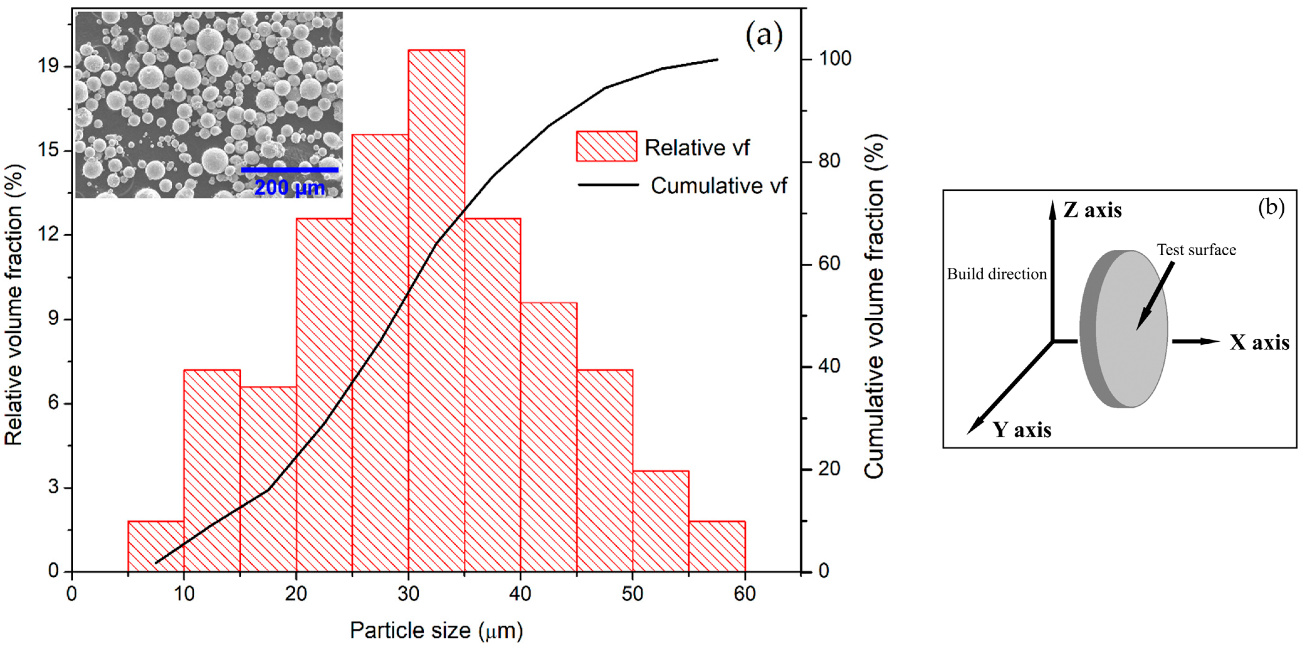
2.1. Materials

In this study, the substrate materials were SLMed and conventionally manufactured (referred to as ‘wrought’) 8620 low-alloy steel. The chemical composition (supplied by the manufacturers) of wrought 8620 steel and the powder used for the SLM process are shown in Table 1.

2.2. Selective Laser Melting

Disc-shaped samples with a size of 15 mm diameter and 5 mm thickness were manufactured from gas-atomized AISI 8620 low-alloy steel powder using a Renishaw® AM250 (Gloucestershire, UK) 3D printer. The powder grains were spherical in form with only a small number of satellite particles, as shown in Figure 1a (inset).
The particle size ranged from 8.5 µm to 59.0 µm in size. The average diameter was between 29.8 and 33.2 µm, with a 95% confidence level. The 50th percentile of the particles was 31.2 µm, which is consistent with the supplier’s data of 32 µm. The disc-shaped specimen was designed using CAD software (SOLIDWORKS®, 2019) before the SLM procedure. The samples were printed with supporting structures to facilitate the specimen removal from the build plate.
During printing, a 1060 nm ytterbium laser (180 W) with a spot size of 75 μm was used. The layer thickness and hatch spacing were 50 μm and 110 μm, respectively. For the bulk volume, a checkerboard hatching method was utilized, with each layer split into 5 × 5 mm2 square blocks. At a laser speed of 600 mm/s, each square block was scanned using parallel tracks that rotated 90 degrees between adjacent blocks. Each layer (n + 1) was rotated 67° with respect to the previous layer (n) to achieve a low temperature gradient in the bulk volume. The build plate was preheated to 170 °C before the start of the scanning. To maintain an inert atmosphere and decrease the risk of oxidation, the build chamber was evacuated until the oxygen concentration in the chamber was decreased to as low as 0.1%, and then a high-grade argon gas was supplied. The samples were printed in such a way that the flat surface of the disc was parallel to the build direction (Figure 1b).

2.3. TiZrN Coating

Before film deposition, all steel samples were sanded progressively with 60 to 1200 grit SiC sandpaper before being polished with 3 µm and 1 µm diamond suspension. The samples were thoroughly cleaned with acetone and ethanol in an ultra-sonication bath for 10 min, rinsed in deionized water, dried in the air, and then used for sputtering. In this study, Ti (99.9%) and Zr (99.9%) targets were co-sputtered using a Nano-36 Sputtering system (Kurt J. Lesker® company, Jefferson Hills, PA, USA) on SLMed and wrought 8620 samples. The samples were placed on a disk, rotating at 20 rpm to achieve a uniform deposition. The sputtering chamber was pumped down to a base pressure of ~9.5 × 10⁻⁶ Torr. High-purity argon gas was supplied to the chamber and the sputtering was carried out at a working pressure of 1.2 × 10⁻² Torr. The substrates were heated to a temperature of 200 °C. A substrate temperature of 200 °C was chosen to improve coating adhesion [52], increase hardness [53], and reduce residual stress [52] and dislocation density [54]. The Ti and Zr targets were co-sputtered via DC and RF guns powered at 150 W and 100 W, respectively. Pre-sputtering in a closed-shutter configuration was performed in argon plasma for 10 min to remove airborne oxides from the target surfaces. Sputtering was carried out for 5 min without the use of nitrogen gas to deposit a pure Ti + Zr film, which improved the adhesion between the substrate and thin film [55]. Then, nitrogen gas was introduced, and sputtering was continued for 35 min. The flow rates of N2 and Ar were 25 sccm and 110 sccm, respectively. The coated SLMed and wrought samples were heat-treated in static air inside a furnace at a temperature of 270 °C for 60 min. During the heat treatment, the samples were laid on an aluminum foil and placed into the furnace. The temperature inside the furnace was raised from room temperature to 270 °C at a rate of 3 °C per minute. After the heat treatment of 60 min, the samples were cooled inside the furnace at the same rate.

2.4. Material Characterization

For metallographic observation, bare polished samples were etched with 5% nital (5% nitric acid and 95% ethanol) solution. The microstructural characterization of the bare and coated samples was carried out with a Hitachi S-3400-II (Tokyo, Japan) scanning electron microscope (SEM) and a Cascade Microtech M150 (Beaverton, OR, USA) optical microscope (OM). Energy-dispersive spectroscopy (EDS) analysis was used to assess the elemental composition of the deposited thin film and corrosion products, using the SEM integrated with an EDS analyzer. The full EDS spectrum was acquired in 100 s during the EDS analysis. Crystallographic orientations and constitutional phases were examined using a Rigaku Ultima IV (Tokyo, Japan) X-ray diffraction (XRD) device using Cu-Kα radiation (1.5408 Å) with a 2θ angle ranging from 10° to 90° with a step size of 0.02° at a speed of 1°/min.

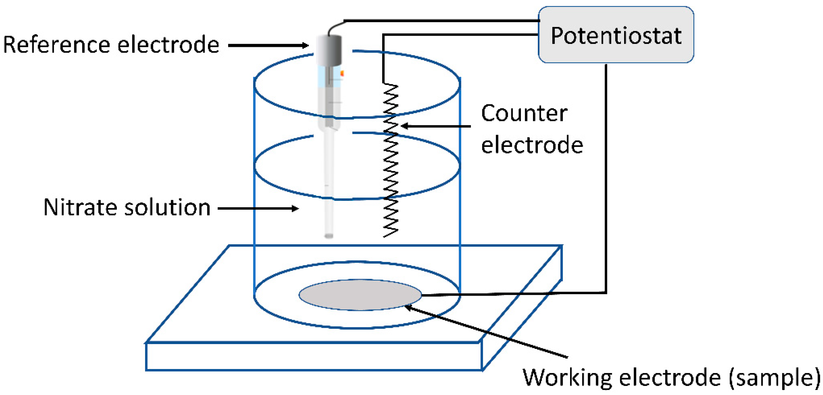
2.5. Electrochemical Test

Electrochemical measurements of SLMed and wrought samples with and without coating were conducted using a Gamry Interface 1000E potentiostat (Warminster, PA, USA) in a conventional three-electrode cell. The 8620 samples, both bare and coated, were used as the working electrode, whereas a platinum coil was used as the counter electrode, and a saturated calomel electrode was used as the reference (Figure 2). All the electrochemical experiments were conducted at a test temperature of 23 ± 2 °C.
To prepare an aqueous solution of 60 wt% NaNO3 + 40 wt% KNO3, 16.99 g NaNO3 and 11.33 g KNO3 (both purchased from Fisher Scientific®, Waltham, MA, USA with a purity of 99% or higher) were each separately dissolved in 200 mL of high-purity Milli-Q water. The resulting NaNO3 and KNO3 solutions had concentrations of 1 M and 0.56 M, respectively. Then, the two solutions were mixed to use as the electrolyte in all electrochemical experiments. After mixing, the pH of the solution was measured to be 7.72 ± 0.04. The electrolyte solution employed in the electrochemical experiments was neither de-aerated nor aerated intentionally.
Before all electrochemical experiments, open-circuit potential (OCP) was monitored until the potential variation was below 0.2 mV/min (up to 2 h). Electrochemical impedance spectroscopy (EIS) was carried out at OCP by applying a sinusoidal AC voltage of amplitude 5 mV over a frequency range of 100 kHz to 10 mHz, recording 10 data points per decade. The potentiodynamic polarization test was started from −0.5 V vs. OCP at a scanning rate of 1 mV/s and continued until +1.0 V vs. OCP. All electrochemical measurements were repeated at least 3 times to ensure reproducibility. Surface characterization after potentiodynamic polarization was conducted using the SEM.

2.6. High-Temperature Oxidation Test

The binary nitrate salt was prepared by mixing NaNO3 and KNO3 at a ratio of 60–40 wt%. The salts were dried for 24 h at 130 °C prior to the start of the experiment. Before the melting process, the salt mixture was blended mechanically in a ceramic crucible. Coated and bare samples of SLMed and wrought 8620 were placed in the crucible. The samples were positioned horizontally in the crucible to ensure full immersion of the samples in the mixture. Next, 40 g of the binary nitrate salt (24 g NaNO3 and 16 g KNO3) was added, completely covering the samples, and then the crucible was placed into the insulated zone of the furnace in the presence of atmospheric air. A temperature of 400 °C was used to melt the salt mixture, which is common in parabolic trough and linear Fresnel CSP technologies [56]. The investigation of solar salt as a prospective heat transfer medium in these technologies at 400 °C and above is currently the subject of active research efforts [57,58,59]. The heating process involved an increase in temperature at a rate of 10 °C per minute until reaching 400 °C, where it was maintained for a duration of 24 h. Samples were then taken out for post-processing and characterization of the corrosion products. To remove the residual salt crust and other contaminants, each sample was cooled slowly in the air outside the furnace, washed with DI water, degreased with ethanol, and dried in the air. To observe the integrity of the film and the deposition of corrosion products on the surface, the samples were investigated using the SEM and EDS.

3. Results and Discussion

3.1. Microstructure

The optical micrographs in Figure 3a,b show the microstructural characteristics of the top view and side view (the top view and side view are explained in Figure 3f) of the SLMed 8620 specimen, respectively. The oval-shaped melt pools due to the laser melting process were evident in the micrograph of the top surface (Figure 3a). The melt pool sizes were not uniform over the whole surface of the specimen. The side surface (Figure 3b), which is parallel to the build direction, showed fish-scale structures caused by the successive layer meting during printing.
The SEM images of the SLMed sample are presented in Figure 3c,d. The microstructure of the SLMed 8620 did not have uniform grains and varied in size and orientation, which can be attributed to the elevated cooling rate inducing non-equilibrium solidification conditions [60]. The microstructure mainly consisted of martensite caused by the higher solidification rate, which did not allow the melted powder to transform from austenite to BCC (body-centered cubic) ferrite [61,62]. The presence of some white streaks was observed in the side view of the SLMed specimen as shown in Figure 3d. These white streaks are believed to be tempered martensite. During the layer-by-layer melting in the SLM process, each layer re-melts and reheats a small portion of the previous layer. The trapped carbon atoms in this reheated area came out of the crystals and precipitated as carbides near the grain boundaries, which could be observed as successive white streaks [63].
Porosity formation is common in the SLM process, which can affect the mechanical and corrosion properties of the 3D-printed components. Porosities can be categorized into three types: (1) cavities, (2) entrapped gas pores, and (3) melt pool boundary porosities [64]. Irregular cavities on the surface of the SLMed 8620 were observed (as shown in Figure 3c) to be dominant, which is believed to be due to insufficient laser energy leading to incomplete melting of the precursor powder [65,66]. Entrapped gas porosities were seen less often, whereas the melt pool boundary porosities were not observed.
The conventionally manufactured 8620 had a ferritic and pearlitic microstructure (as shown in Figure 3e), which was completely different from that of the SLMed specimen. The ferrite grains and pearlite colonies in wrought 8620 appeared to be uniformly dispersed throughout the matrix. This kind of microstructure is formed when the pro-eutectoid steel is cooled slowly in atmospheric conditions.
The XRD patterns of the bare SLMed and wrought 8620 samples (as shown in Figure 4a) showed a crystalline phase with peaks at the 2θ location of 44.63°, 64.87°, and 82.21°, respectively, which is consistent with other studies [43,67]. Since the BCC structure of the ferrite and BCT (body-centered tetragonal) structure of the martensite cannot be distinguished by XRD, both samples had peaks at the same positions. The bare SLMed and wrought samples showed differences in relative intensities of the peaks, though in both cases, the preferred orientation was the (110) plane, and the intensity was lower for the bare SLMed 8620. It can also be noted that the intensity of the (211) peak was higher compared to the (200) peak in the wrought specimen. But these peaks had approximately the same intensity in the bare SLMed sample, indicating an equal distribution of these two planes. In both samples, there was no evidence of peak broadening.
The structure of the coating was investigated using XRD (Figure 4a) and GIXRD (Figure 4b), which confirmed the presence of crystalline TiZrN. The TiZrN (200) peak was observed at a 2θ angle of 42.62°. This peak was observed in between the ZrN (200) and TiN (200) peaks, not shown here but reported elsewhere [68]. Moreover, the findings are consistent with previously published results of TiN [69,70,71], ZrN [72], and TiZrN [51,73,74]. The α—(110) peak from the 8620 steel substrate was also present in both XRD and GIXRD.

3.2. TiZrN Coating

Figure 5 shows the morphology of the coating on SLMed and wrought samples. The manufacturing defects on the SLMed sample were seen in the SEM image of the coated surface (Figure 5a). However, in the case of coated wrought 8620, as illustrated in Figure 5b, such flaws were not visible. The coated samples were further examined under an optical microscope (OP), and optical micrographs revealed the presence of pores on the substrates of both coated SLMed (Figure 5c) and wrought 8620 (Figure 5d), which were also documented in previous research [75]. Optical micrographs also revealed that coated SLMed samples had a higher number of pores than wrought ones due to the intrinsic cavities formed during the melting process as discussed earlier.
The film composition is presented in Table 2, which was obtained via EDS. The coating was composed of about 23 at% titanium and about 7 at% zirconium with the rest made up of nitrogen. The composition of the film on the SLMed and wrought substrates was also examined, and there was minimal to no difference in the composition. To inspect the thickness of the TiZrN coating, cross-sectional analysis was carried out using an SEM, as shown in Figure 5e. The film thickness, formed at 200 °C substrate heating, was estimated to be roughly 475 ± 35 nm.
The coated samples (SLMed and wrought) were further heat-treated to relieve the compressive residual stresses since the thermal energy this provides helps reorganize atoms and diffuse away point defects [76]. Heat treatment can also increase the corrosion resistance via the formation of TiO2 and ZrO2 [77]. However, heat treatment in an oxygen-rich environment might lead to excessive oxide formation, which could increase the residual stress. That is why a comparatively lower temperature was used to relieve some of the residual stress and control the oxide formation. The heat treatment caused a significant amount of oxygen (31 wt%) on the film as identified through EDS analysis.
The heat treatment of the coated samples resulted in the formation of titanium and zirconium oxides. Since the coating exhibited some pores, the steel substrate exposed through the pores may be converted to iron oxides. The following reactions have been proposed during the heat-treatment process [78,79,80].
2 F e 3 + + 6 e + 3 / 2 O 2 F e 2   O 3
F e 2 + + 2 e + 4 F e 2 O 3 F e 3   O 4
T i Z r N + O 2 T i O 2   + Z r O 2   + N 2
It has been reported that if low-carbon steel is heat-treated for a short duration (less than 120 min), the majority of the oxides are Fe3O4 [81]. Moreover, some titanium and zirconium atoms might not react with nitrogen (during sputtering) and oxygen (during heat treatment), leaving behind unreacted titanium and zirconium atoms [79]. Thus, the coating consisted of TiZrN, TiO2, ZrO2 and unreacted Ti and Zr after heat treatment. The presence of nitrogen and oxygen on the film was confirmed via EDS after heat treatment (Table 2).

3.3. Potentiodynamic Polarization

Moisture absorption by solar salt is a common occurrence which accelerates the corrosion of steel [27,82]. Thus, it is necessary to evaluate the electrochemical performance of the samples in aqueous solution. Potentiodynamic polarization curves of the SLMed and wrought 8620 with and without coating in an aqueous solution of NaNO3 (1 M) + KNO3 (0.56 M) are shown in Figure 6a.
The electrochemical parameters, such as corrosion potential (Ecorr), corrosion current density (Icorr), and Tafel slopes (βA and βC), extracted from potentiodynamic polarization curves are summarized in Table 3. As seen in the table, the corrosion potential of the coated wrought, coated SLMed, bare wrought, and bare SLMed samples was −276.0 ± 17.1 mV (SCE), −442.3 ± 13.6 mV (SCE), −665.7 ± 38.1 mV (SCE), and −709.7 ± 46.3 mV (SCE), respectively. The corrosion potential of the coated samples was more positive than the bare samples. This implies improved corrosion resistance of the coated samples. The corrosion current densities of bare wrought and SLMed 8620 were 4.69 ± 0.95 µA/cm2 and 4.80 ± 0.32 µA/cm2, respectively, which signifies a similar corrosion mechanism in bare samples. When the 8620 samples were coated with the TiZrN film via magnetron sputtering, the corrosion current densities decreased to 0.59 ± 0.06 µA/cm2 and 0.55 ± 0.07 µA/cm2, respectively, which indicates that the TiZrN coating enhanced the corrosion resistance of both SLMed and wrought 8620.
The electrochemical reactions during the potentiodynamic polarization scan on bare samples resulted in the formation of corrosion products containing iron oxides. This was confirmed using the SEM and EDS and has been discussed in Section 3.5. In case of the coated samples, the TiZrN film transformed to TiZrN-O state via oxygen incorporation into the film [83]. Unreacted Ti and Zr transformed to TiO2 and ZrO2, respectively, which acted as corrosion barrier and resulted in considerably higher Tafel slopes in coated samples than the bare ones.
Brown et al. [84] investigated the corrosion resistance of the TiN and ZrN film on AISI 304 stainless steel in 0.5 N NaCl solution and reported two mechanisms responsible for the improvement in the resistance of the film. First is the replacement of the nitrogen atoms of the film by oxygen atoms and the formation of zirconium oxides. Second is the incorporation of oxygen atoms in the film creating Zr-O-N. In this study as well, the improved corrosion resistance of the TiZrN film is believed to be due to the incorporation of oxygen atoms in the film and formation of zirconium and titanium oxides. Zirconium is readily oxidized, which makes it resistant to chemical attacks [85,86,87]. Furthermore, the capacity of titanium to build corrosion-resistant oxide is well recognized [88,89]. Thus, the presence of such outstanding oxide formers (i.e., Zr and Ti) on the film provided enhanced corrosion resistance to the 8620 substrates.

3.4. Electrochemical Impedance Spectroscopy

The Bode impedance plots, Bode phase plots, and Nyquist plots from an electrochemical impedance spectroscopy (EIS) test in an aqueous solution of 60–40 wt% NaNO3 + KNO3 at room temperature, conducted over a frequency range from 10 mHz to 100 kHz, are shown in Figure 6b–d, respectively. The Bode impedance plot (as shown in Figure 6b) represents the area normalized total impedance, |Z|, vs. frequency. At the lowest frequency (0.01 Hz), a considerably higher (one order of magnitude) |Z| of coated samples compared to that of bare ones demonstrated improved barrier characteristics of the coating on 8620 steel. The phase angles of both bare and coated 8620 were near the zero degree at a high frequency (~10 kHz) in the Bode phase plots (Figure 6c), implying that the impedance at a high frequency can be represented by resistance only. With decreasing frequency, the phase angles dropped too, indicating the capacitive behavior of the electric double layer. At a frequency of ~1 Hz, the phase angles of the bare samples (both wrought and SLMed) approached −60°, whereas the phase angles of the coated wrought and coated SLMed samples approached −70° and −55°, respectively. This variation in phase angle of coated 8620 was due to the intrinsic porosities or defects in the SLMed samples. The phase angle shift of greater than −90° (ZPhase > −90°) instead of pure capacitance (ZPhase = −90°) was observed because of the non-uniform charge distribution across the electric double layer, defects in the coating, and surface roughness [90]. That is why the capacitive behavior of the electric double layer and the coating is illustrated by a constant phase element (CPE), which will be discussed in the next paragraph. The impedance spectra of Nyquist plots (Figure 6d) were made up of depressed semicircles. The overall resistance of the system was calculated by extrapolating these semicircles towards the low-frequency region, i.e., the intersection of the fitted curves with the Zreal axis. The greater the radius of the semicircle, the greater the resistance of the coating [91]. The semicircle radius of the Nyquist plots for coated samples were recorded as larger compared to the bare ones, which clearly demonstrated the influence of the coating on both SLMed and wrought 8620 steel.
The quantitative electrochemical data were obtained by fitting in Gamry Echem Analyst software (version 7.04) using an equivalent electrical circuit (EEC), as shown in Figure 6e. In the EEC, Rs denotes the solution resistance; CPEf and Rf represent the capacitance and resistance of the coating on the surface of 8620 steel, respectively; and CPEdl and Rct indicate the capacitance and charge transfer resistance of the electric double layer. The faradaic and non-faradaic processes at the electrode/electrolyte interface are represented by the parallel combination of Rct and CPEdl. As discussed earlier, the double layer and the coating capacitance have less phase shift than pure capacitance and are represented as constant phase elements in the EEC. The impedance of the CPEf and CPEdl can be defined as
Z CPE = Q j ω n 1
where j = 1 refers to the imaginary component of the impedance, ω denotes the angular frequency, Q represents imaginary admittance of the CPE, and n denotes the exponent of the CPE of value 0 < n < 1. A pure capacitor has a n value between 0.93 and 1, whereas an impure capacitor has a n value of less than 0.93 [80].
Table 4 shows the quantitative data for each element in the EEC model acquired by fitting EIS spectra. The chi-squared (χ2) values indicated that the goodness of fit was in the order of 10−3. Both coated wrought and SLMed 8620 showed approximately 7–8 times higher Rct values (8.3 ± 3.2 kΩ·cm2, and 9.8 ± 1.1 kΩ·cm2, respectively) compared to bare wrought and SLMed (1.1 ± 0.1 kΩ·cm2, and 1.3 ± 0.2 kΩ·cm2). A high charge transfer resistance (Rct) indicates a reduced ionic movement [92]. Additionally, the values of total resistance, Rt = Rs + Rf + Rct, of coated wrought and SLMed (9.4 ± 2.8 kΩ·cm2 and 12.9 ± 1.9 kΩ·cm2) samples were approximately 9–10 times higher than bare wrought and SLMed 8620 (1.2 ± 0.1 kΩ·cm2, 1.3 ± 0.2 kΩ·cm2), respectively, which indicated that the TiZrN coating enhanced the corrosion resistance of the 8620 low-alloy steel, be it wrought or SLMed. Lower Qdl values associated with coated wrought (64.5 ± 35.4 μS-sn cm−2) and coated SLMed samples (57.3 ± 24.3 μS-sn cm−2) indicated better barrier characteristics of the TiZrN coating than bare wrought (853 ± 149 μS-sn cm−2) and bare SLMed (1180 ± 170 μS-sn cm−2) 8620. Moreover, the Qf values of coated wrought (100.4 ± 39.0 μS-sn cm−2) and coated SLMed (96.9 ± 31.7 μS-sn cm−2) samples were 5–10 times lower than bare wrought (484 ± 113 μS-sn cm−2) and bare SLMed (844 ± 192 μS-sn cm−2) samples, respectively.
In summary, the electrochemical parameters estimated from the EIS test indicated that the TiZrN coating improved the corrosion resistance of SLMed and wrought 8620 in the aqueous solution of NaNO3 + KNO3, consistent with the potentiodynamic polarization test. Incorporation of oxygen in the thin film and the formation of titanium and zirconium oxides were responsible for the improved corrosion resistance of the film. Also, the enhancement in electrochemical properties was partially due to the barrier characteristics of the film, which reduced the number of reaction sites, hence improving the corrosion resistance.

3.5. Surface Analysis after Potentiodynamic Polarization

The post-corrosion SEM images of bare SLMed, bare wrought, coated SLMed, and coated wrought samples are presented in Figure 7. The bare SLMed 8620 had more localized corrosion attacks (Figure 7a), whereas the bare wrought 8620 had uniform corrosion throughout the whole exposed surface (Figure 7b). The coated samples showed fewer corrosion pits compared to the bare ones, which signifies the enhanced corrosion resistance of the film. The corrosion attacks on the coated SLMed 8620 were mostly on the existing pores, as seen in Figure 7c. A breakdown in the thin film was observed on few spots of the coated wrought sample, where corrosion products were visible (Figure 7d). There was no peeling of the thin film from the SLMed and wrought samples due to the good adhesion between the thin film and the steel substrate. The failures of the thin film are thought to be caused by the pores that already existed in the film. Corrosive media penetrated through the pores and caused corrosion on the substrate. However, the corrosion was much less severe in coated 8620 than in the bare counterparts.
The corrosion pit on the coated SLMed sample and EDS line scan over the pit are shown in Figure 8a,c, respectively. Similarly, the corrosion pit on the coated wrought sample and the EDS line scan above the pit are shown in Figure 8b,d, respectively. The line scans show that the corrosion products inside the pits were high in oxygen, indicating the presence of oxides. The surfaces of the bare samples after PD were also analyzed with EDS and a similar concentration of oxygen to that of the coated 8620 was observed.

3.6. High-Temperature Oxidation Analysis

Cross-sectional SEM images of SLMed and wrought 8620 with and without coating after corrosion tests in molten solar salt at 400 °C for 24 h are presented in Figure 9. The thickness from the cross-sectional images revealed that the bare SLMed (Figure 9a) and wrought 8620 (Figure 9b) had a similar thickness of corrosion scale. In particular, the obtained oxide layer after the 24 h immersion test for the bare SLMed 8620 was around 2.62 ± 0.24 µm, and for the bare wrought 8620 it was around 3.76 ± 0.15 µm. The EDS line scan over the corrosion scale of the bare sample indicated the presence of only iron and oxygen in the corrosion products as shown in Figure 9c.
No corrosion products were observed on top of the coated 8620 in the cross-sectional images (Figure 9d,e), indicating that the thin-film coating was corrosion-resistant. However, EDS measurements after the high-temperature corrosion test revealed the presence of iron in the coating (Figure 9f). Because of the pores in the film, a tiny quantity of molten salts might have passed through and reacted with the steel substrate, resulting in iron oxides.
Surface SEM images of bare SLMed and wrought 8620 revealed completely covered surfaces with layers of corrosion products as indicated on Figure 10a,b. From the figures, it is evident that the surface morphologies of the corroded bare SLMed and wrought 8620 were quite different. The surface of the SLMed sample was covered by needle-shaped corrosion products, whereas the surface of the wrought sample was covered by many granular precipitates. The corrosion products on the SLMed specimen were found to be loosely attached to the substrate and had fallen off from several spots. Corrosion products on SLMed 8620 were prone to spallation due to porosity and thermal stress that developed during the oxide formation stage and subsequent specimen cooling to room temperature [93]. The surfaces of the coated samples showed no sign of corrosion products as presented in Figure 10c,d, indicating the enhanced corrosion resistance of the coating.
Surfaces of SLMed and wrought samples (both bare and coated) after the high-temperature corrosion test were analyzed pointwise with EDS, and the results are summarized in Table 5. The main components of the corrosion products of bare samples were identified to be Fe and O. The corrosion products are believed to be magnetite (Fe3O4) and hematite (Fe2O3). The iron oxides were formed by iron ions migrating outward and oxygen ions migrating inward. The corrosion products in other molten nitrate salt experiments on low-chromium and stainless-steel samples are sodium ferrite (NaFeO2), iron oxides (Fe2O3, Fe3O4), iron–chromium spinel (FeCr2O4), and chromium oxide (Cr2O3) [26]. Gonzalez et al. reported the formation of hematite, magnetite, and magnesioferrite (Fe2MgO4) during the corrosion test of carbon steel A516.Gr70 in solar salt at 390 °C [34]. Similar types of corrosion products have also been reported in other studies [15,19,22,24,29]. The presence of magnesium oxide, as reported in previous studies, was from the impurity of the solar salt. Dorcheh et al. reported the multilayer corrosion scale of X20 steel in solar salt [26]. However, in this study, the corrosion scale was composed of only one layer due to the short time of the experiment and the presence of lower chromium and nickel in the substrate. At a temperature of 400 °C, the only element from the nitrate salts that participated in the surface reaction was oxygen, as no sodium or potassium were observed in EDS. Compounds of sodium, such as NaFeO2, were reported at a very high temperature, e.g., above 600 °C [14,26,38].
In the presence of oxide ions (O2−), the following reactions were expected for the formation of iron oxides on the sample surface [27].
NO3 + 2e ↔ NO2 + O2−
Fe + O2− ↔ FeO + 2e
3FeO + O2− ↔ Fe3O4 + 2e
2 Fe3O4 + O2− ↔ 3Fe2O3 + 2e
Molten nitrate salts dissolve oxygen when they come into contact with air. Dissolved oxygen can speed up corrosion by promoting processes (Equations (6)–(8)) through an extra reaction (Equation (9)) [26]:
O2 + 2e ↔ O2−
Coated samples also showed the presence of iron and oxygen on the surface, which is consistent with the earlier result presented in the cross-sectional EDS as shown in Figure 9f. A tiny percentage of silicon was probably found as a result of salt contamination, while a minor quantity of sodium was found in the molten salt’s leftover remnants.

4. Conclusions

In this research, additively manufactured and wrought 8620 low-alloy steel was coated with a TiZrN thin film via magnetron sputtering and subsequently studied in a nitrate salt solution and salt bath environment to investigate its corrosion resistance. The conclusions are as follows:
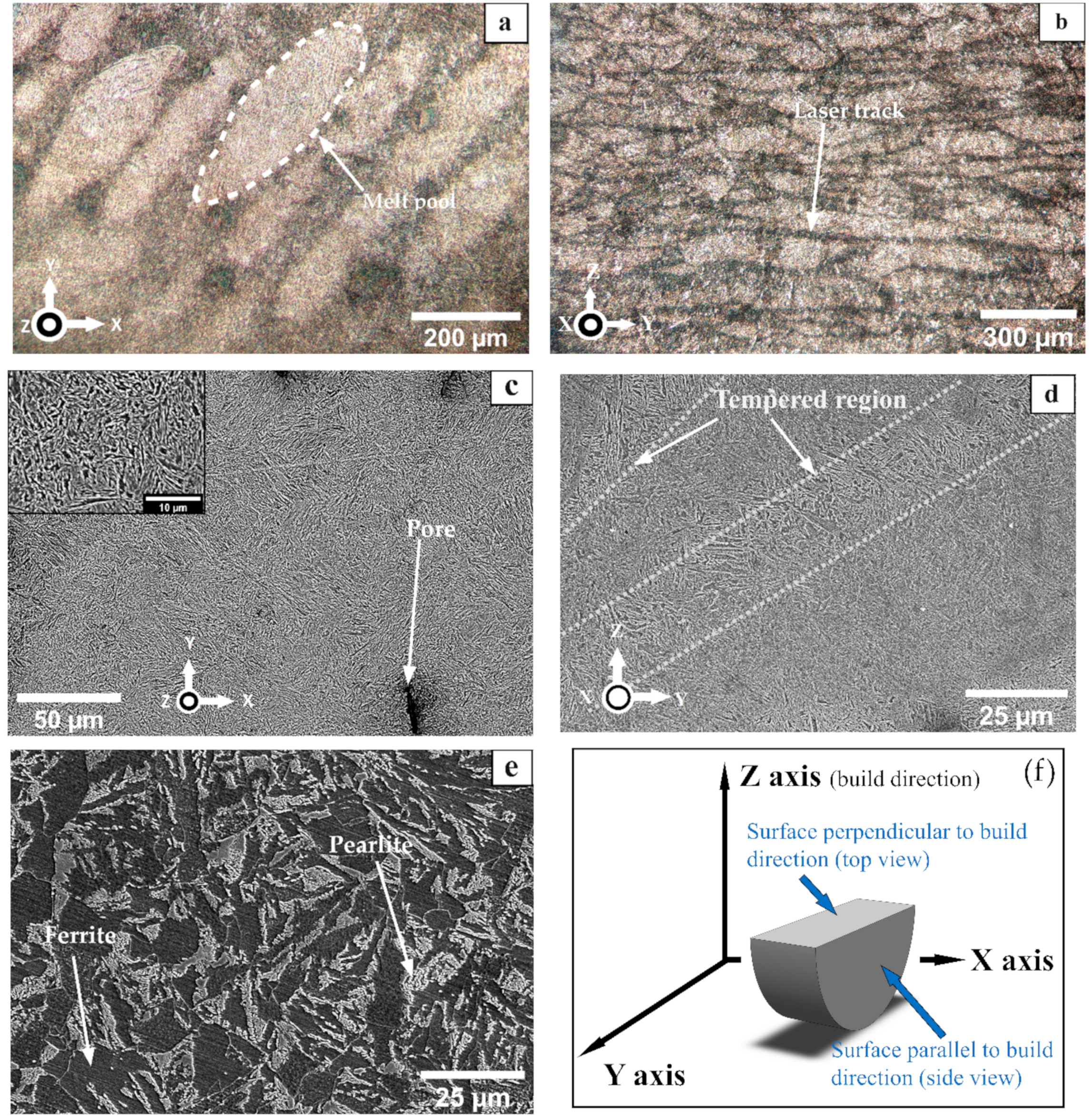
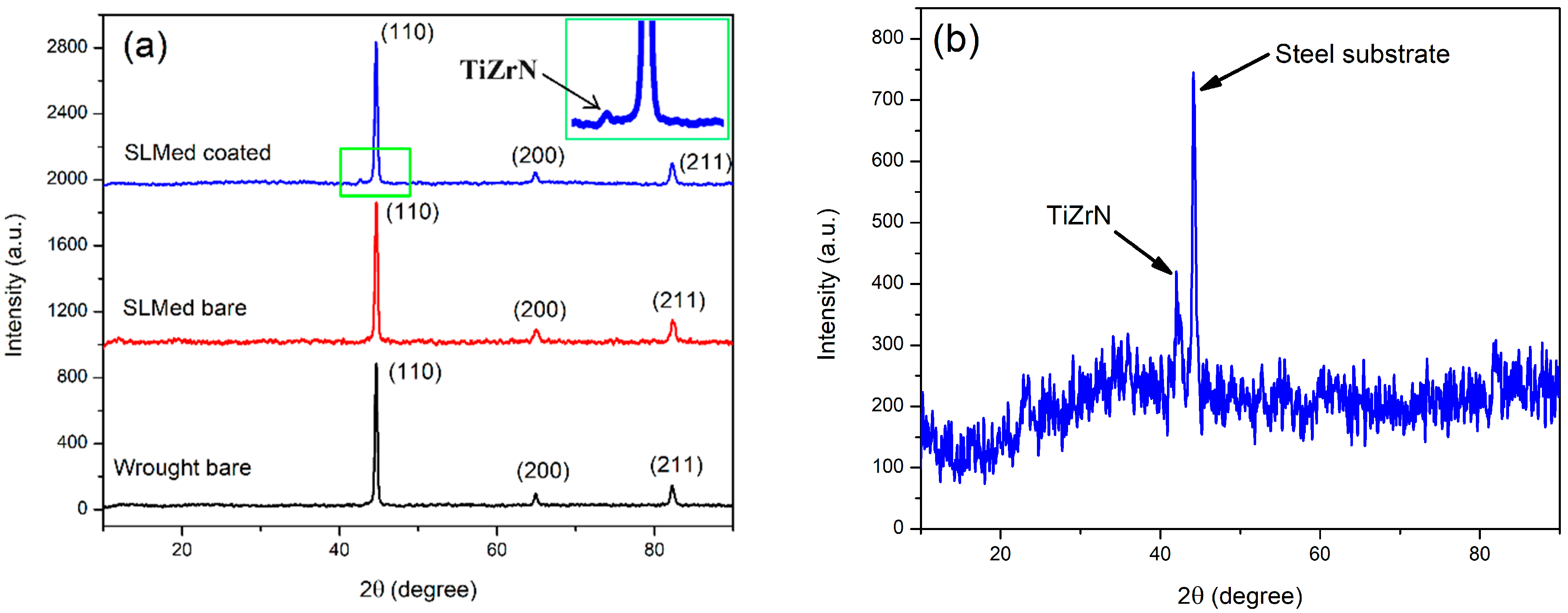
  • Test specimens of 8620 steel were prepared via selective laser melting. The microstructure of the as-built bare SLMed sample, after etching, showed a tempered martensitic phase. This microstructure resulted from the fast solidification rate of the 3D printing process. The microstructure of wrought 8620, on the other hand, showed a ferritic–pearlitic microstructure.
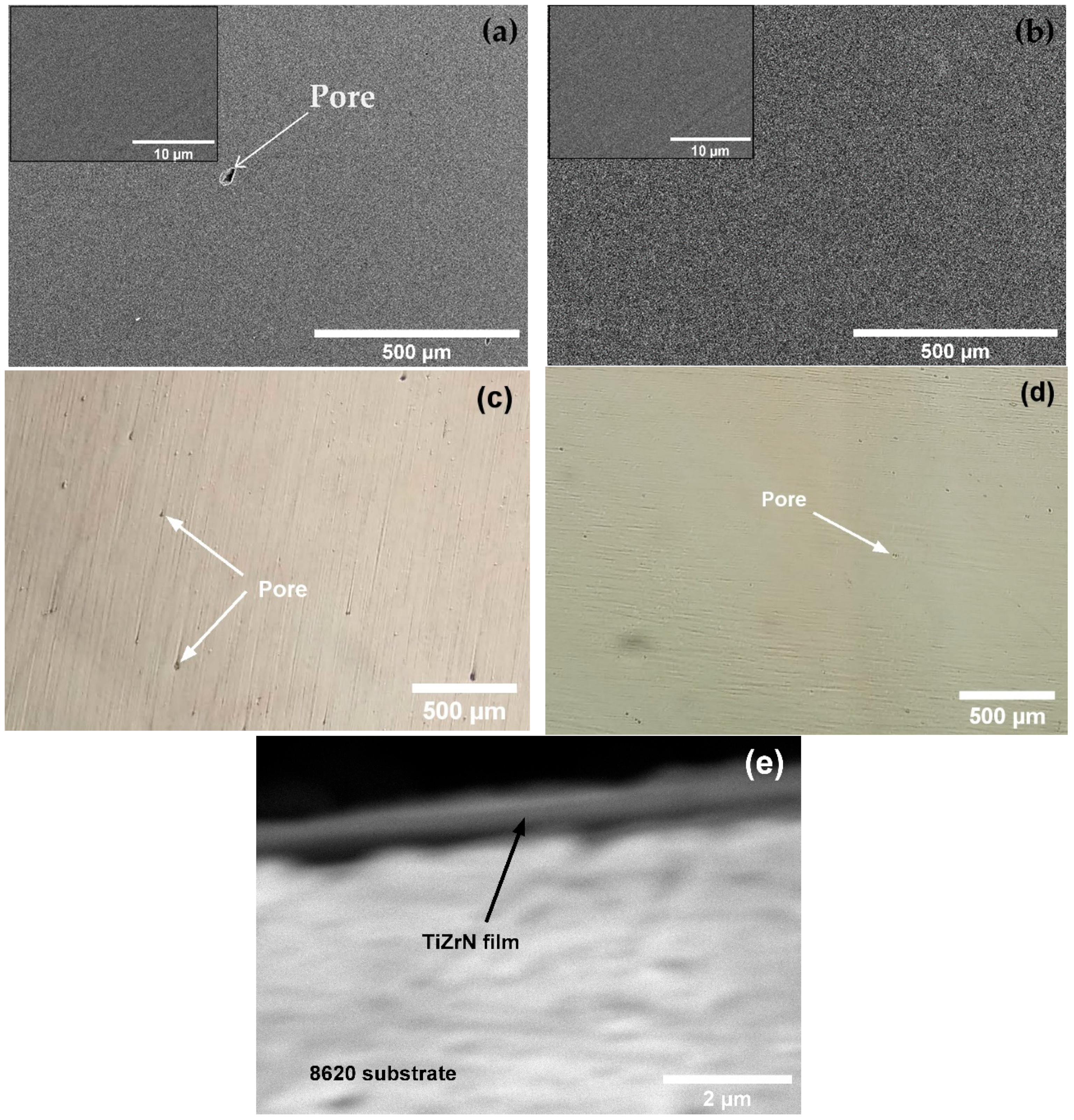
  • Both SLMed and wrought samples were coated via the magnetron-sputtered TiZrN thin film. The TiZrN film exhibited good adhesion to both SLMed and wrought 8620 samples, although they had dissimilar microstructures. However, the presence of pores on the deposited film was observed more on the SLMed sample than the wrought sample due to the existing pores on the surface of the SLMed sample generated during 3D printing. Coated samples were further heat-treated at 270 °C to reduce residual stress of the deposited film and partially oxidize to increase corrosion resistance. EDS analysis of the heat-treated film confirmed the presence of Ti, Zr, N, and O.
  • In potentiodynamic polarization and electrochemical impedance spectroscopy tests in an aqueous nitrate salt solution, bare SLMed and wrought 8620 showed similar performance. This signifies that 8620 steel manufactured via SLM is as good as wrought 8620 steel in terms of corrosion resistance in nitrate salt solution. All coated samples (both SLMed and wrought) exhibited better corrosion resistance in nitrate salt solution. In particular, coated samples showed an ~8-fold lower corrosion current density, a~7-fold higher charge transfer resistance, and a ~20-fold lower double layer capacitance than their bare counterparts.
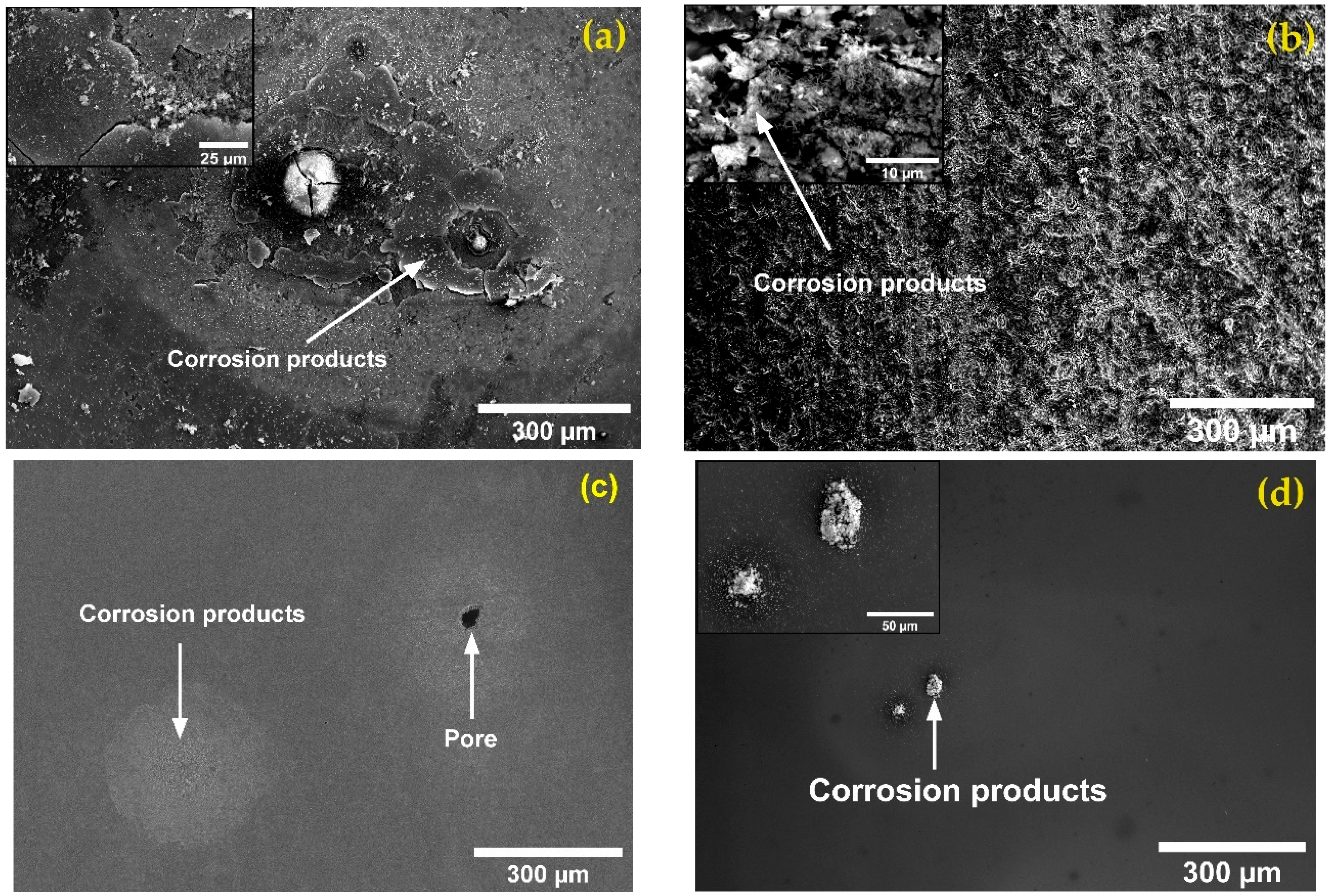
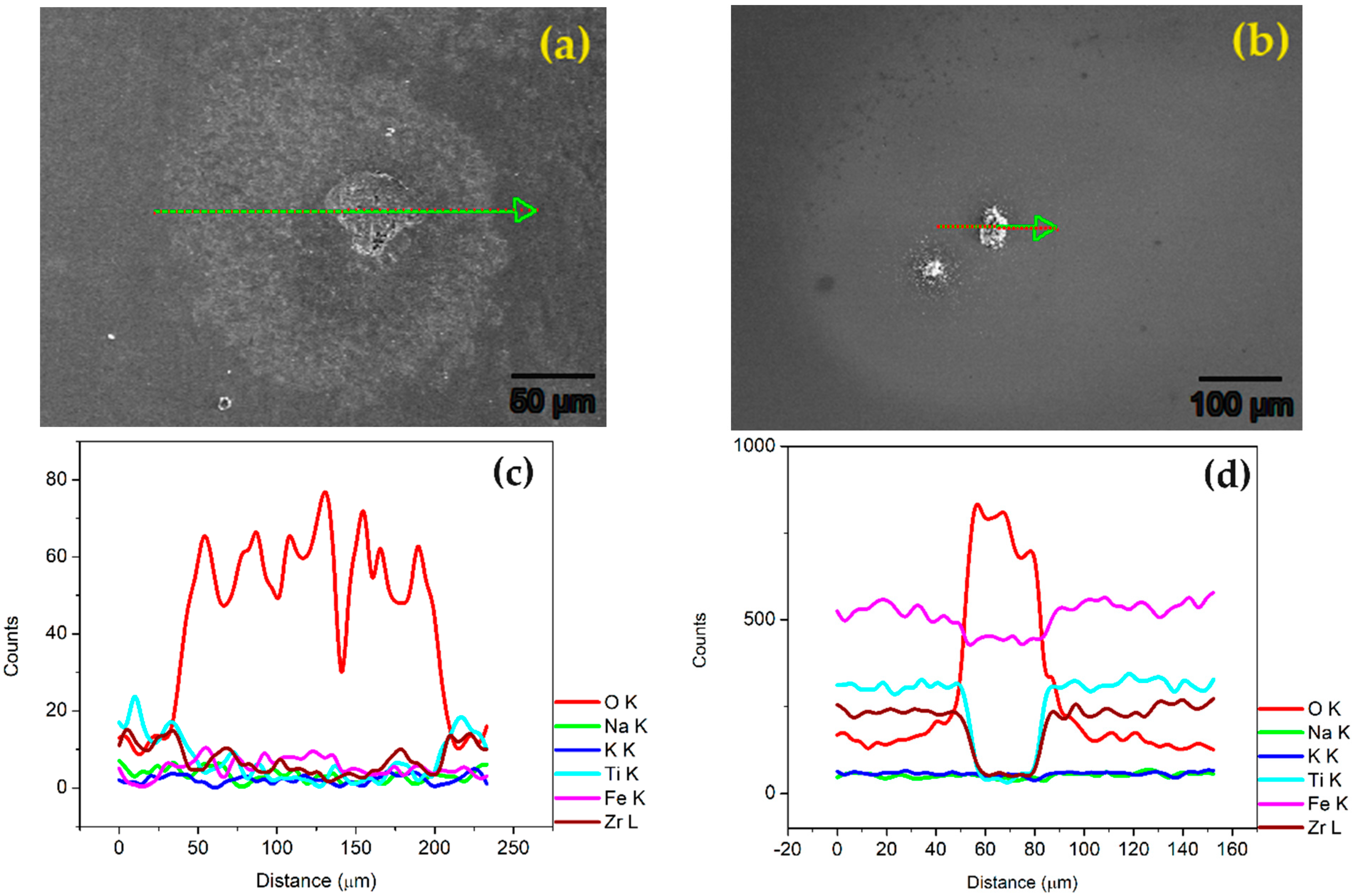
  • SEM observation of the corroded samples after the potentiodynamic polarization test showed that the coated SLMed and wrought samples underwent mild corrosion attacks predominantly on the existing pores present on the film. The bare samples, on the other hand, were subjected to significant corrosion attacks, resulting in the deposition of oxides. This signifies the corrosion protection capability of the deposited film.
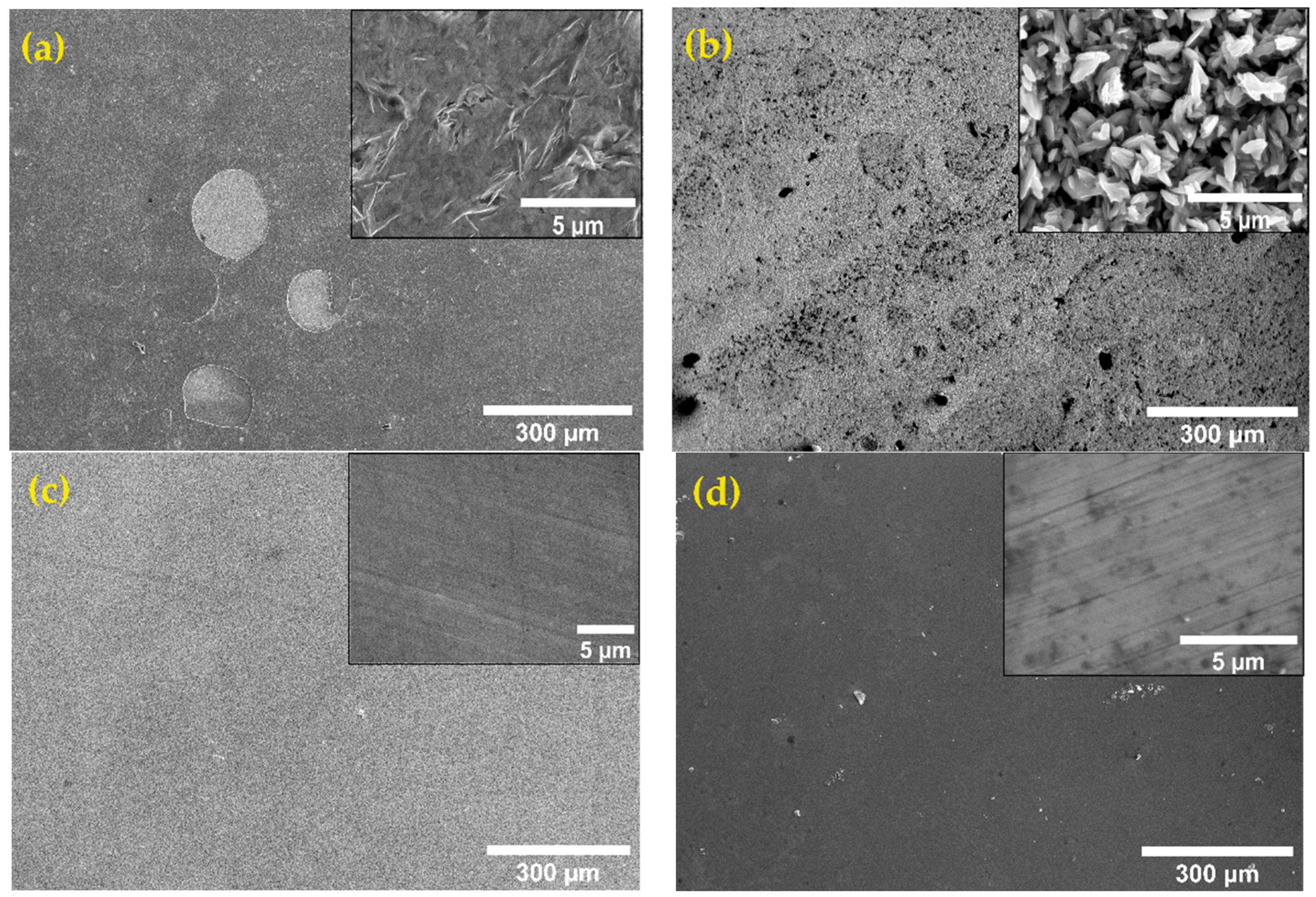
  • The high-temperature corrosion test in molten solar salt revealed that the coated samples did not have any corrosion product, but the bare samples had a thick layer of corrosion products on top of the sample. EDS analysis of the corrosion products on the bare samples revealed the presence of magnetite (Fe3O4) and hematite (Fe2O3). Thus, bare SLMed and wrought 8620 steel are susceptible to significant corrosion in a molten-salt environment which could be reduced via TiZrN thin-film coating.
  • The improvement in corrosion resistance of the thin-film-coated sample is attributed to the incorporation of oxygen, the formation of zirconium and titanium oxides, and the lower number of reaction sites in the film.
  • Future research endeavors could center around a comprehensive examination of the long-term corrosion resistance exhibited by the TiZrN film. As upcoming concentrated solar power (CSP) technologies are anticipated to operate at elevated temperatures surpassing 600 °C, it is imperative to assess the performance of the TiZrN film under such conditions. Additionally, exploring alternative additive manufacturing techniques like wire arc additive manufacturing (WAAM), known for its rapid and cost-effective metal component printing, presents an intriguing avenue. Investigating the corrosion resistance of WAAM-produced components in molten-salt environments could provide valuable insights.

Author Contributions

Conceptualization, E.H.S., M.A.M. and I.S.; Methodology, E.H.S.; Formal analysis, E.H.S. and M.A.M.; Investigation, E.H.S.; Data curation, M.A.M.; Writing—original draft, E.H.S.; Writing—review & editing, W.H. and I.S.; Supervision, M.A.M., W.H. and I.S. All authors have read and agreed to the published version of the manuscript.

Funding

This research received no external funding.

Institutional Review Board Statement

Not applicable.

Informed Consent Statement

Not applicable.

Data Availability Statement

The datasets generated during and/or analyzed during the current study are available from the corresponding author on reasonable request.

Acknowledgments

The authors would like to acknowledge the support from the College of Science and Engineering of Central Michigan University.

Conflicts of Interest

The authors declare that they have no known competing financial interests or personal relationships that could have appeared to influence the work reported in this paper.

References

  1. Hussain, A.; Arif, S.M.; Aslam, M. Emerging Renewable and Sustainable Energy Technologies: State of the Art. Renew. Sustain. Energy Rev. 2017, 71, 12–28. [Google Scholar] [CrossRef]
  2. González-Roubaud, E.; Pérez-Osorio, D.; Prieto, C. Review of Commercial Thermal Energy Storage in Concentrated Solar Power Plants: Steam vs. Molten Salts. Renew. Sustain. Energy Rev. 2017, 80, 133–148. [Google Scholar] [CrossRef]
  3. Mao, A.; Park, J.H.; Han, G.Y.; Seo, T.; Kang, Y. Heat Transfer Characteristics of High Temperature Molten Salt for Storage of Thermal Energy. Korean J. Chem. Eng. 2010, 27, 1452–1457. [Google Scholar] [CrossRef]
  4. Madathil, P.K.; Balagi, N.; Saha, P.; Bharali, J.; Rao, P.V.C.; Choudary, N.V.; Ramesh, K. Preparation and Characterization of Molten Salt Based Nanothermic Fluids with Enhanced Thermal Properties for Solar Thermal Applications. Appl. Therm. Eng. 2016, 109, 901–905. [Google Scholar] [CrossRef]
  5. Pramod, K.M.; Rao, P.V.C.; Choudary, N.V.; Ramesh, K. Novel Methodology to Prepare Homogenous Ternary Molten Salts for Concentrated Solar Power Applications and Their Thermo-Physical Characterization. Appl. Therm. Eng. 2016, 109, 906–910. [Google Scholar] [CrossRef]
  6. Kim, H.; Jo, B. Anomalous Increase in Specific Heat of Binary Molten Salt-Based Graphite Nanofluids for Thermal Energy Storage. Appl. Sci. 2018, 8, 1305. [Google Scholar] [CrossRef]
  7. An, X.-H.; Cheng, J.-H.; Su, T.; Zhang, P. Determination of Thermal Physical Properties of Alkali Fluoride/Carbonate Eutectic Molten Salt. AIP Conf. Proc. 2017, 1850, 070001. [Google Scholar]
  8. Fereres, S.; Prieto, C.; Giménez-Gavarrell, P.; Rodríguez, A.; Sánchez-Jiménez, P.E.; Pérez-Maqueda, L.A. Molten Carbonate Salts for Advanced Solar Thermal Energy Power Plants: Cover Gas Effect on Fluid Thermal Stability. Sol. Energy Mater. Sol. Cells 2018, 188, 119–126. [Google Scholar] [CrossRef]
  9. Wei, X.; Song, M.; Peng, Q.; Ding, J.; Yang, J. Quaternary Chloride Eutectic Mixture for Thermal Energy Storage at High Temperature. Energy Procedia 2015, 75, 417–422. [Google Scholar] [CrossRef]
  10. Ding, W.; Bonk, A.; Bauer, T. Molten Chloride Salts for next Generation CSP Plants: Selection of Promising Chloride Salts & Study on Corrosion of Alloys in Molten Chloride Salts. AIP Conf. Proc. 2019, 2126, 200014. [Google Scholar]
  11. Li, X.; Li, N.; Liu, W.; Tang, Z.; Wang, J. Unrevealing the Thermophysical Properties and Microstructural Evolution of MgCl2–NaCl–KCl Eutectic: FPMD Simulations and Experimental Measurements. Sol. Energy Mater. Sol. Cells 2020, 210, 110504. [Google Scholar] [CrossRef]
  12. Muñoz-Sánchez, B.; Nieto-Maestre, J.; Iparraguirre-Torres, I.; García-Romero, A.; Sala-Lizarraga, J.M. Molten Salt-Based Nanofluids as Efficient Heat Transfer and Storage Materials at High Temperatures. An Overview of the Literature. Renew. Sustain. Energy Rev. 2018, 82, 3924–3945. [Google Scholar] [CrossRef]
  13. Aljaerani, H.A.; Samykano, M.; Pandey, A.K.; Kadirgama, K.; Saidur, R. Thermo-Physical Properties and Corrosivity Improvement of Molten Salts by Use of Nanoparticles for Concentrated Solar Power Applications: A Critical Review. J. Mol. Liq. 2020, 314, 113807. [Google Scholar] [CrossRef]
  14. Kruizenga, A.; Gill, D. Corrosion of Iron Stainless Steels in Molten Nitrate Salt. Energy Procedia 2014, 49, 878–887. [Google Scholar] [CrossRef]
  15. Fernández, A.G.; Rey, A.; Lasanta, I.; Mato, S.; Brady, M.P.; Pérez, F.J. Corrosion of Alumina-Forming Austenitic Steel in Molten Nitrate Salts by Gravimetric Analysis and Impedance Spectroscopy: Corrosion in Molten Nitrate Salts. Mater. Corros. 2014, 65, 267–275. [Google Scholar] [CrossRef]
  16. Pumps for Concentrated Solar Power Plants. Available online: https://www.ruhrpumpen.com/en/markets/power-generation/concentrated-solar-power-plants (accessed on 29 January 2022).
  17. VEY and VNY Molten Salt Pump for Concentrated Solar Power. Available online: https://www.sulzer.com/en/shared/products/vey-molten-salt-for-concentrated-solar-power (accessed on 29 January 2022).
  18. Gomes, A.; Navas, M.; Uranga, N.; Paiva, T.; Figueira, I.; Diamantino, T.C. High-Temperature Corrosion Performance of Austenitic Stainless Steels Type AISI 316L and AISI 321H, in Molten Solar Salt. Sol. Energy 2019, 177, 408–419. [Google Scholar] [CrossRef]
  19. Goods, S.H.; Bradshaw, R.W. Corrosion of Stainless Steels and Carbon Steel by Molten Mixtures of Commercial Nitrate Salts. J. Mater. Eng. Perform. 2004, 13, 78–87. [Google Scholar] [CrossRef]
  20. Zhang, X.; Zhang, C.; Wu, Y.; Lu, Y. Experimental Research of High Temperature Dynamic Corrosion Characteristic of Stainless Steels in Nitrate Eutectic Molten Salt. Sol. Energy 2020, 209, 618–627. [Google Scholar] [CrossRef]
  21. Wang, Q.; Zhou, D.; Chen, Y.; Wu, Z. Corrosion of Stainless Steel 316 in a Ternary Nitrate Salt and Its Composite with Expanded Graphite for Solar Thermal Applications. Sol. Energy Mater. Sol. Cells 2021, 219, 110823. [Google Scholar] [CrossRef]
  22. Xie, W.; Ding, J.; Wei, X.; Wang, W.; Xia, G.; Xing, J. Corrosion Resistance of Stainless Steel and Pure Metal in Ternary Molten Nitrate for Thermal Energy Storage. Energy Procedia 2019, 158, 4897–4902. [Google Scholar] [CrossRef]
  23. Baraka, A.; Abdel-Rohman, A.I.; Hosary, A.A.E. Corrosion of Mild Steel in Molten Sodium Nitrate–Potassium Nitrate Eutectic. Br. Corros. J. 1976, 11, 44–46. [Google Scholar] [CrossRef]
  24. García-Martín, G.; Lasanta, M.I.; Encinas-Sánchez, V.; de Miguel, M.T.; Pérez, F.J. Evaluation of Corrosion Resistance of A516 Steel in a Molten Nitrate Salt Mixture Using a Pilot Plant Facility for Application in CSP Plants. Sol. Energy Mater. Sol. Cells 2017, 161, 226–231. [Google Scholar] [CrossRef]
  25. Ruiz-Cabañas, F.J.; Prieto, C.; Osuna, R.; Madina, V.; Fernández, A.I.; Cabeza, L.F. Corrosion Testing Device for In-Situ Corrosion Characterization in Operational Molten Salts Storage Tanks: A516 Gr70 Carbon Steel Performance under Molten Salts Exposure. Sol. Energy Mater. Sol. Cells 2016, 157, 383–392. [Google Scholar] [CrossRef]
  26. Dorcheh, A.S.; Durham, R.N.; Galetz, M.C. High Temperature Corrosion in Molten Solar Salt: The Role of Chloride Impurities. Mater. Corros. 2017, 68, 943–951. [Google Scholar] [CrossRef]
  27. Fernández, A.G.; Galleguillos, H.; Pérez, F.J. Thermal Influence in Corrosion Properties of Chilean Solar Nitrates. Sol. Energy 2014, 109, 125–134. [Google Scholar] [CrossRef]
  28. Fernández, A.G.; Cortes, M.; Fuentealba, E.; Pérez, F.J. Corrosion Properties of a Ternary Nitrate/Nitrite Molten Salt in Concentrated Solar Technology. Renew. Energy 2015, 80, 177–183. [Google Scholar] [CrossRef]
  29. Fernández, A.G.; Muñoz-Sánchez, B.; Nieto-Maestre, J.; García-Romero, A. High Temperature Corrosion Behavior on Molten Nitrate Salt-Based Nanofluids for CSP Plants. Renew. Energy 2019, 130, 902–909. [Google Scholar] [CrossRef]
  30. Nithiyanantham, U.; Grosu, Y.; González-Fernández, L.; Zaki, A.; Igartua, J.M.; Faik, A. Development of Molten Nitrate Salt Based Nanofluids for Thermal Energy Storage Application: High Thermal Performance and Long Storage Components Life-Time. AIP Conf. Proc. 2019, 2126, 200025. [Google Scholar]
  31. Nithiyanantham, U.; Grosu, Y.; Anagnostopoulos, A.; Carbó-Argibay, E.; Bondarchuk, O.; González-Fernández, L.; Zaki, A.; Igartua, J.M.; Navarro, M.E.; Ding, Y.; et al. Nanoparticles as a High-Temperature Anticorrosion Additive to Molten Nitrate Salts for Concentrated Solar Power. Sol. Energy Mater. Sol. Cells 2019, 203, 110171. [Google Scholar] [CrossRef]
  32. Nieto-Maestre, J.; Muñoz-Sánchez, B.; Fernández, A.G.; Faik, A.; Grosu, Y.; García-Romero, A. Compatibility of Container Materials for Concentrated Solar Power with a Solar Salt and Alumina Based Nanofluid: A Study under Dynamic Conditions. Renew. Energy 2020, 146, 384–396. [Google Scholar] [CrossRef]
  33. Nithiyanantham, U.; Grosu, Y.; González-Fernández, L.; Zaki, A.; Igartua, J.M.; Faik, A. Corrosion Aspects of Molten Nitrate Salt-Based Nanofluids for Thermal Energy Storage Applications. Sol. Energy 2019, 189, 219–227. [Google Scholar] [CrossRef]
  34. Gonzalez, M.; Nithiyanantham, U.; Carbó-Argibay, E.; Bondarchuk, O.; Grosu, Y.; Faik, A. Graphitization as Efficient Inhibitor of the Carbon Steel Corrosion by Molten Binary Nitrate Salt for Thermal Energy Storage at Concentrated Solar Power. Sol. Energy Mater. Sol. Cells 2019, 203, 110172. [Google Scholar] [CrossRef]
  35. Piquot, J.; Nithiyanantham, U.; Grosu, Y.; Faik, A. Spray-Graphitization as a Protection Method against Corrosion by Molten Nitrate Salts and Molten Salts Based Nanofluids for Thermal Energy Storage Applications. Sol. Energy Mater. Sol. Cells 2019, 200, 110024. [Google Scholar] [CrossRef]
  36. Grosu, Y.; Anagnostopoulos, A.; Navarro, M.E.; Ding, Y.; Faik, A. Inhibiting Hot Corrosion of Molten Li2CO3-Na2CO3-K2CO3 Salt through Graphitization of Construction Materials for Concentrated Solar Power. Sol. Energy Mater. Sol. Cells 2020, 215, 110650. [Google Scholar] [CrossRef]
  37. Fähsing, D.; Oskay, C.; Meißner, T.M.; Galetz, M.C. Corrosion Testing of Diffusion-Coated Steel in Molten Salt for Concentrated Solar Power Tower Systems. Surf. Coat. Technol. 2018, 354, 46–55. [Google Scholar] [CrossRef]
  38. Meißner, T.M.; Oskay, C.; Bonk, A.; Grégoire, B.; Donchev, A.; Solimani, A.; Galetz, M.C. Improving the Corrosion Resistance of Ferritic-Martensitic Steels at 600 °C in Molten Solar Salt via Diffusion Coatings. Sol. Energy Mater. Sol. Cells 2021, 227, 111105. [Google Scholar] [CrossRef]
  39. Treewiriyakitja, P.; Joy-A-Ka, S.; Promdirek, P. Study of Corrosion Resistance of Stainless Steel AISI430 Coated by Slurry Aluminizing in Molten Nitrate Salt. Mater. Today Proc. 2018, 5, 9630–9634. [Google Scholar] [CrossRef]
  40. Soleimani Dorcheh, A.; Galetz, M.C. Slurry Aluminizing: A Solution for Molten Nitrate Salt Corrosion in Concentrated Solar Power Plants. Sol. Energy Mater. Sol. Cells 2016, 146, 8–15. [Google Scholar] [CrossRef]
  41. Kondaiah, P.; Pitchumani, R. Fractal Textured Surfaces for High Temperature Corrosion Mitigation in Molten Salts. Sol. Energy Mater. Sol. Cells 2021, 230, 111281. [Google Scholar] [CrossRef]
  42. Thirugnanasambantham, K.G.; Ganesh Kumar, A.G. Mechanistic Studies on Degradation in Sliding Wear Behavior of Carburized AISI 8620 Steel at 100 °C under Unlubricated Conditions. Mater. Today Proc. 2018, 5, 6258–6267. [Google Scholar] [CrossRef]
  43. Kumar, R.; Ghosh, P.K.; Kumar, S. Thermal and Metallurgical Characteristics of Surface Modification of AISI 8620 Steel Produced by TIG Arcing Process. J. Mater. Process. Technol. 2017, 240, 420–431. [Google Scholar] [CrossRef]
  44. Cao, Y.; Xu, L.; Zhang, G.; Shi, J.; Wang, M. Rolling Contact Fatigue Properties of SAE 8620 Steel after Case Carburizing. J. Iron Steel Res. Int. 2016, 23, 711–716. [Google Scholar] [CrossRef]
  45. Asi, O.; Can, A.Ç.; Pineault, J.; Belassel, M. The Effect of High Temperature Gas Carburizing on Bending Fatigue Strength of SAE 8620 Steel. Mater. Des. 2009, 30, 1792–1797. [Google Scholar] [CrossRef]
  46. Tillmann, W.; Hagen, L.; Stangier, D.; Lopes Dias, N.F.; Görtz, J.; Kensy, M.D. Lapping and Polishing of Additively Manufactured 316L Substrates and Their Effects on the Microstructural Evolution and Adhesion of PVD CrAlN Coatings. Surf. Coat. Technol. 2021, 428, 127905. [Google Scholar] [CrossRef]
  47. Salhi, F.; Aissani, L.; Fellah, M.; Chadli, A.; Cheriet, A.; Belgroune, A.; Nouveau, C.; Obrosov, A.; Abdul Samad, M.; Alhussein, A. Experimental Investigation of Structural, Wetting, Mechanical and Tribological Properties of TiZrN Thin Films Deposited by Magnetron Sputtering. Surf. Interfaces 2021, 27, 101519. [Google Scholar] [CrossRef]
  48. Cui, W.; Cheng, J.; Liu, Z. Bio-Tribocorrosion Behavior of a Nanocrystalline TiZrN Coating on Biomedical Titanium Alloy. Surf. Coat. Technol. 2019, 369, 79–86. [Google Scholar] [CrossRef]
  49. Donohue, L.A.; Cawley, J.; Brooks, J.S. Deposition and Characterisation of Arc-Bond Sputter TixZryN Coatings from Pure Metallic and Segmented Targets. Surf. Coat. Technol. 1995, 72, 128. [Google Scholar] [CrossRef]
  50. Lin, Y.-W.; Chen, H.-A.; Yu, G.-P.; Huang, J.-H. Effect of Bias on the Structure and Properties of TiZrN Thin Films Deposited by Unbalanced Magnetron Sputtering. Thin Solid Films 2016, 618, 13–20. [Google Scholar] [CrossRef]
  51. Lin, Y.-W.; Huang, J.-H.; Yu, G.-P. Effect of Nitrogen Flow Rate on Properties of Nanostructured TiZrN Thin Films Produced by Radio Frequency Magnetron Sputtering. Thin Solid Films 2010, 518, 7308–7311. [Google Scholar] [CrossRef]
  52. Kang, D.; Kim, Y.S.; Kim, J.N.; Park, I.K. Characteristics of TiN Thin Films Deposited by Substrate Temperature Variables Using Scanning Acoustic Microscopy. Appl. Sci. 2022, 12, 3571. [Google Scholar] [CrossRef]
  53. Hariharan, R.; Raja, R.; Golden Renjith Nimal, R.J.; Refaai, M.R.A.; Ravi, S.; Allasi, H.L. Characterization of TiZrN and TaZrN Nanocomposite Multilayer Coating Deposited via RF/DC Magnetron Sputtering on AISI4140 Steel. Adv. Mater. Sci. Eng. 2021, 2021, 8273708. [Google Scholar] [CrossRef]
  54. Ashok, K.; Subramanian, B.; Kuppusami, P.; Jayachandran, M. Effect of Substrate Temperature on Structural and Materials Properties of Zirconium Nitride Films on D9 Steel Substrates. Cryst. Res. Technol. 2009, 44, 511–516. [Google Scholar] [CrossRef]
  55. Helmersson, U.; Johansson, B.O.; Sundgren, J.E.; Hentzell, H.T.G.; Billgren, P. Adhesion of Titanium Nitride Coatings on Highspeed Steels. J. Vac. Sci. Technol. 1985, 3, 308. [Google Scholar] [CrossRef]
  56. Xu, X.; Vignarooban, K.; Xu, B.; Hsu, K.; Kannan, A.M. Prospects and Problems of Concentrating Solar Power Technologies for Power Generation in the Desert Regions. Renew. Sustain. Energy Rev. 2016, 53, 1106–1131. [Google Scholar] [CrossRef]
  57. Ruegamer, T.; Kamp, H.; Kuckelkorn, T.; Schiel, W.; Weinrebe, G.; Nava, P.; Riffelmann, K.; Richert, T. Molten Salt for Parabolic Trough Applications: System Simulation and Scale Effects. Energy Procedia 2014, 49, 1523–1532. [Google Scholar] [CrossRef]
  58. Giaconia, A.; Iaquaniello, G.; Metwally, A.A.; Caputo, G.; Balog, I. Experimental Demonstration and Analysis of a CSP Plant with Molten Salt Heat Transfer Fluid in Parabolic Troughs. Sol. Energy 2020, 211, 622–632. [Google Scholar] [CrossRef]
  59. Al-Barqi, A.S.; Bukharin, N.; Zazoum, B.; El Hassan, M. Design of a 100 MW Concentrated Solar Power Linear Fresnel Plant in Riyadh, Saudi Arabia: A Comparison between Molten Salt and Liquid Sodium Thermal Energy Storage. Energy Rep. 2022, 8, 697–704. [Google Scholar] [CrossRef]
  60. Al-Mamun, N.S.; Haider, W.; Shabib, I. Corrosion Resistance of Additively Manufactured 316L Stainless Steel in Chloride–thiosulfate Environment. Electrochim. Acta 2020, 362, 137039. [Google Scholar] [CrossRef]
  61. Sabuz, E.H.; Pitts-Reed, D.; Haider, W.; Shabib, I. Electrochemical Performance of Additively Manufactured 8620 Low-Alloy Steel: Effect of Acetic Acid. In Proceedings of the Steel Properties & Applications in Conjunction with Materials Science & Technology 2022, Pittsburgh, PA, USA, 9–12 October 2022; Association for Iron & Steel Technology: Warrendale, PA, USA, 2022; p. 16. [Google Scholar]
  62. Sabuz, E.H.; Noor-A-Alam, M.; Haider, W.; Shabib, I. Improving the Mechanical and Electrochemical Performance of Additively Manufactured 8620 Low Alloy Steel via Boriding. Corros. Mater. Degrad. 2023, 4, 623–643. [Google Scholar] [CrossRef]
  63. Binkley, M. Microstructure Development in Multi-Pass Laser Melting of Aisi 8620 Steel; Purdue University: West Lafayette, IN, USA, 2020. [Google Scholar]
  64. Kazemipour, M.; Mohammadi, M.; Mfoumou, E.; Nasiri, A.M. Microstructure and Corrosion Characteristics of Selective Laser-Melted 316L Stainless Steel: The Impact of Process-Induced Porosities. JOM 2019, 71, 3230–3240. [Google Scholar] [CrossRef]
  65. Zhang, B.; Li, Y.; Bai, Q. Defect Formation Mechanisms in Selective Laser Melting: A Review. Chin. J. Mech. Eng. 2017, 30, 515–527. [Google Scholar] [CrossRef]
  66. Kempen, K.; Thijs, L.; Van Humbeeck, J.; Kruth, J.-P. Processing AlSi10Mg by Selective Laser Melting: Parameter Optimisation and Material Characterisation. Mater. Sci. Technol. 2015, 31, 917–923. [Google Scholar] [CrossRef]
  67. Marulanda, D.M.; Cortés, J.G.; Pérez, M.A.; García, G. Microstructure and Mechanical Properties of AISI 8620 Steel Processed by ECAP. MRS Proc. 2014, 1611, 89–94. [Google Scholar] [CrossRef]
  68. Lin, Y.-W.; Huang, J.-H.; Yu, G.-P. Microstructure and Corrosion Resistance of Nanocrystalline TiZrN Films on AISI 304 Stainless Steel Substrate. J. Vac. Sci. Technol. Vac. Surf. Films 2010, 28, 774–778. [Google Scholar] [CrossRef]
  69. Valvoda, V.; Kuzĕl, R.; Cĕrný, R.; Dobiásŏvá, L. Detailed X-Ray Diffraction Study of Titanium Nitride Coatings: Some Interpretation Problems. Mater. Sci. Eng. A 1988, 104, 223–234. [Google Scholar] [CrossRef]
  70. Qi, R.; Pan, L.; Feng, Y.; Wu, J.; Li, W.; Wang, Z. Evolution of Chemical, Structural, and Mechanical Properties of Titanium Nitride Thin Films Deposited under Different Nitrogen Partial Pressure. Results Phys. 2020, 19, 103416. [Google Scholar] [CrossRef]
  71. Chang, C.-C.; Nogan, J.; Yang, Z.-P.; Kort-Kamp, W.J.M.; Ross, W.; Luk, T.S.; Dalvit, D.A.R.; Azad, A.K.; Chen, H.-T. Highly Plasmonic Titanium Nitride by Room-Temperature Sputtering. Sci. Rep. 2019, 9, 15287. [Google Scholar] [CrossRef]
  72. Lee, J.-K.; Yang, G.-S. Preparation of TiAlN/ZrN and TiCrN/ZrN Multilayers by RF Magnetron Sputtering. Trans. Nonferrous Met. Soc. China 2009, 19, 795–799. [Google Scholar] [CrossRef]
  73. Chinsakolthanakorn, S.; Buranawong, A.; Witit-anun, N.; Chaiyakun, S.; Limsuwan, P. Characterization of Nanostructured TiZrN Thin Films Deposited by Reactive DC Magnetron Co-Sputtering. Procedia Eng. 2012, 32, 571–576. [Google Scholar] [CrossRef]
  74. Phae-ngam, W.; Horprathum, M.; Chananonnawathorn, C.; Lertvanithphol, T.; Samransuksamer, B.; Songsiriritthigul, P.; Nakajima, H.; Chaiyakun, S. Oblique Angle Deposition of Nanocolumnar TiZrN Films via Reactive Magnetron Co-Sputtering Technique: The Influence of the Zr Target Powers. Curr. Appl. Phys. 2019, 19, 894–901. [Google Scholar] [CrossRef]
  75. Ajenifuja, E.; Popoola, A.P.I.; Popoola, O.M. Thickness Dependent Chemical and Microstructural Properties of DC Reactive Magnetron Sputtered Titanium Nitride Thin Films on Low Carbon Steel Cross-Section. J. Mater. Res. Technol. 2019, 8, 377–384. [Google Scholar] [CrossRef]
  76. Huang, J.-H.; Kuo, K.-L.; Yu, G.-P. Oxidation Behavior and Corrosion Resistance of Vacuum Annealed ZrN-Coated Stainless Steel. Surf. Coat. Technol. 2019, 358, 308–319. [Google Scholar] [CrossRef]
  77. Milošev, I.; Strehblow, H.-H.; Navinšek, B. Comparison of TiN, ZrN and CrN Hard Nitride Coatings: Electrochemical and Thermal Oxidation. Thin Solid Films 1997, 303, 246–254. [Google Scholar] [CrossRef]
  78. Bertrand, N.; Desgranges, C.; Poquillon, D.; Lafont, M.C.; Monceau, D. Iron Oxidation at Low Temperature (260–500 °C) in Air and the Effect of Water Vapor. Oxid. Met. 2010, 73, 139–162. [Google Scholar] [CrossRef]
  79. Bhuvaneswari, H.B.; Rajagopal Reddy, V.; Chandramani, R.; Mohan Rao, G. Annealing Effects on Zirconium Nitride Films. Appl. Surf. Sci. 2004, 230, 88–93. [Google Scholar] [CrossRef]
  80. Taweesup, K.; Visuttipitukul, P.; Yongvanich, N.; Lothongkum, G. Corrosion Behavior of Ti-Cr-N Coatings on Tool Steel Substrates Prepared Using DC Magnetron Sputtering at Low Growth Temperatures. Surf. Coat. Technol. 2019, 358, 732–740. [Google Scholar] [CrossRef]
  81. Larose, S.; Rapp, R.A. Review of Low-Temperature Oxidation of Carbon Steels and Low-Alloy Steels for Use as High-Level Radioactive Waste Package Materials; Center for Nuclear Waste Regulatory Analyses: San Antonio, TX, USA, 1997. [Google Scholar]
  82. Fernández, Á.G.; Cabeza, L.F. Molten Salt Corrosion Mechanisms of Nitrate Based Thermal Energy Storage Materials for Concentrated Solar Power Plants: A Review. Sol. Energy Mater. Sol. Cells 2019, 194, 160–165. [Google Scholar] [CrossRef]
  83. Massiani, Y.; Medjahed, A.; Gravier, P.; Argème, L.; Fedrizzi, L. Electrochemical Study of Titanium Nitride Films Obtained by Reactive Sputtering. Thin Solid Films 1990, 191, 305–316. [Google Scholar] [CrossRef]
  84. Brown, R.; Alias, M.N.; Fontana, R. Effect of Composition and Thickness on Corrosion Behavior of TiN and ZrN Thin Films. Surf. Coat. Technol. 1993, 62, 467–473. [Google Scholar] [CrossRef]
  85. Gebert, A.; Gostin, P.F.; Schultz, L. Effect of Surface Finishing of a Zr-Based Bulk Metallic Glass on Its Corrosion Behaviour. Corros. Sci. 2010, 52, 1711–1720. [Google Scholar] [CrossRef]
  86. Khan, M.M.; Shabib, I.; Haider, W. A Combinatorially Developed Zr-Ti-Fe-Al Metallic Glass with Outstanding Corrosion Resistance for Implantable Medical Devices. Scr. Mater. 2019, 162, 223–229. [Google Scholar] [CrossRef]
  87. Khan, M.M.; Deen, K.M.; Haider, W. Combinatorial Development and Assessment of a Zr-Based Metallic Glass for Prospective Biomedical Applications. J. Non-Cryst. Solids 2019, 523, 119544. [Google Scholar] [CrossRef]
  88. Jabed, A.; Rahman, Z.U.; Khan, M.M.; Haider, W.; Shabib, I. Combinatorial Development and In Vitro Characterization of the Quaternary Zr–Ti–X–Y (X–Y = Cu–Ag/Co–Ni) Metallic Glass for Prospective Bioimplants. Adv. Eng. Mater. 2019, 21, 1900726. [Google Scholar] [CrossRef]
  89. Jabed, A.; Khan, M.M.; Camiller, J.; Greenlee-Wacker, M.; Haider, W.; Shabib, I. Property Optimization of Zr-Ti-X (X = Ag, Al) Metallic Glass via Combinatorial Development Aimed at Prospective Biomedical Application. Surf. Coat. Technol. 2019, 372, 278–287. [Google Scholar] [CrossRef]
  90. Igual Muñoz, A.; García Antón, J.; Guiñón, J.L.; Pérez Herranz, V. The Effect of Chromate in the Corrosion Behavior of Duplex Stainless Steel in LiBr Solutions. Corros. Sci. 2006, 48, 4127–4151. [Google Scholar] [CrossRef]
  91. Maruf, M.A.; Rizvi, S.M.M.; Noor-A-Alam, M.; Shin, D.; Haider, W.; Shabib, I. Corrosion Resistance and Thermal Stability of Sputtered Fe44Al34Ti7N15 and Al61Ti11N28 Thin Films for Prospective Application in Oil and Gas Industry. Prog. Nat. Sci. Mater. Int. 2021, 31, 688–697. [Google Scholar] [CrossRef]
  92. Ćurković, L.; Ćurković, H.O.; Salopek, S.; Renjo, M.M.; Šegota, S. Enhancement of Corrosion Protection of AISI 304 Stainless Steel by Nanostructured Sol–Gel TiO2 Films. Corros. Sci. 2013, 77, 176–184. [Google Scholar] [CrossRef]
  93. Pineda, F.; Mallco, A.; De Barbieri, F.; Carrasco, C.; Henriquez, M.; Fuentealba, E.; Fernández, Á.G. Corrosion Evaluation by Electrochemical Real-Time Tracking of VM12 Martensitic Steel in a Ternary Molten Salt Mixture with Lithium Nitrates for CSP Plants. Sol. Energy Mater. Sol. Cells 2021, 231, 111302. [Google Scholar] [CrossRef]
Figure 1. (a) 8620 low-alloy steel powder particle size distribution and (b) schematic of 3D printing orientation.
Coatings 13 01998 g001
Figure 2. Schematic diagram of the electrochemical test setup.
Coatings 13 01998 g002
Figure 3. Optical micrograph of SLMed sample surface (a) perpendicular to build direction and (b) parallel to build direction. SEM image of SLMed sample surface (c) perpendicular to build direction and (d) parallel to build direction. (e) SEM image of wrought 8620. (f) Surfaces observed with the SEM and optical microscope.
Coatings 13 01998 g003
Figure 4. (a) XRD pattern of bare wrought, bare SLMed, and coated SLMed 8620. (b) GI-XRD of coated SLMed sample.
Coatings 13 01998 g004
Figure 5. SEM image of the coating on (a) SLMed and (b) wrought 8620. Optical micrograph of the coating on (c) SLMed and (d) wrought samples. (e) Cross-sectional SEM image of the TiZrN film on the 8620 steel substrate.
Coatings 13 01998 g005
Figure 6. Electrochemical responses of coated wrought, coated SLMed, bare wrought, and bare SLMed samples in an aqueous solution of 60–40 wt% NaNO3 + KNO3 at 23 ± 1 °C. (a) Potentiodynamic polarization plots, (b) Bode impedance plots, (c) Bode phase plots, (d) Nyquist plots, and (e) equivalent electrical circuit (EEC) model of the systems.
Coatings 13 01998 g006
Figure 7. Surface morphology of the corroded samples after potentiodynamic polarization tests in an aqueous solution of 60–40 wt% NaNO3 + KNO3. (a) bare SLMed, (b) bare wrought, (c) coated SLMed, and (d) coated wrought 8620 steel.
Coatings 13 01998 g007
Figure 8. SEM images and EDS line scans of the corrosion products of (a,c) coated SLMed and (b,d) coated wrought 8620, respectively. Green arrow indicates EDS line scan.
Coatings 13 01998 g008
Figure 9. Cross-sectional SEM and EDS images after high-temperature corrosion tests in molten solar salt at 400 °C for 24 h. SEM images of (a) bare SLMed, (b) bare wrought, (d) coated SLMed, and (e) coated wrought samples. EDS (c) line scan over the corrosion scale of bare wrought, and (f) point scan on the coating of SLMed 8620. Green arrow and red dot indicate EDS line scan and point scan, respectively.
Coatings 13 01998 g009
Figure 10. Surface morphology of corroded samples after high-temperature corrosion tests in molten solar salt at 400 °C for 24 h. SEM images of (a) bare SLMed, (b) bare wrought, (c) coated SLMed, and (d) coated wrought samples.
Coatings 13 01998 g010
Table 1. Elemental compositions (wt%) of 8620 low-alloy steel used in this study.
ElementCrNiMnMoSiCSPFe
Powder0.550.560.710.20.290.190.0050.015Bal.
Wrought0.40.40.70.150.150.180.040.035Bal.
Table 2. Elemental analysis (atomic percentage) of the thin film.
ElementTiZrON
Before heat treatment22.7 ± 0.96.9 ± 0.2-Bal.
After heat treatment26.6 ± 0.37.4 ± 0.231.4 ± 0.8Bal.
Table 3. Quantitative data extracted from Tafel extrapolation of potentiodynamic polarization scan (n = 3).
SampleEcorr (mV)Icorr (µA/cm2)βA (mV/Decade)βC (mV/Decade)
Coated wrought−276.0 ± 17.10.59 ± 0.06121.2 ± 35.9176.1 ± 23.6
Coated SLMed−442.3 ± 13.60.55 ± 0.07144.3 ± 57.1261.0 ± 96.2
Bare wrought−665.7 ± 38.14.69 ± 0.9551.5 ± 12.2206.3 ± 26.9
Bare SLMed−709.7 ± 46.34.80 ± 0.3254.0 ± 5.7186.6 ± 14.8
Table 4. Quantitative parameters of EEC elements obtained by fitting the experimental EIS spectra (n = 3).
SamplesRs
(Ω·cm2)
Rct
(kΩ·cm2)
Qdl
μS-sn cm−2
Rf
(Ω·cm2)
Qf
μS-sn cm−2
Rt
(kΩ·cm2)
Goodness of Fit (10−3)
Coated wrought65.9 ± 6.78.3 ± 3.264.5 ± 35.41098 ± 451100.4 ± 39.09.4 ± 2.84.2 ± 1.9
Coated SLMed61.0 ± 2.49.8 ± 1.157.3 ± 24.33058 ± 92396.9 ± 31.712.9 ± 1.92.7 ± 0.7
Bare wrought15.7 ± 5.01.1 ± 0.1853 ± 14946.7 ± 5.8484 ± 1131.2 ± 0.16.7 ± 0.8
Bare SLMed7.2 ± 0.11.3 ± 0.21180 ± 17017.5 ± 3.5844 ± 1921.3 ± 0.27.7 ± 2.0
Table 5. Elemental distribution (wt%) after high-temperature corrosion test.
ElementCoated SLMed (wt%)Coated Wrought (wt%)Bare SLMed
(wt%)
Bare Wrought
(wt%)
O21.8 ± 0.320.2 ± 0.933.7 ± 2.022.3 ± 1.3
Fe46.7 ± 1.849.0 ± 1.963.8 ± 2.176.8 ± 1.5
N3.4 ± 0.52.8 ± 0.32.5 ± 0.20.2 ± 0.1
Ti13.1 ± 0.714.5 ± 0.4--
Zr7.1 ± 0.97.5 ± 0.3--
Si4.7 ± 0.43.9 ± 0.1--
Na3.2 ± 0.32.2 ± 0.3--
Disclaimer/Publisher’s Note: The statements, opinions and data contained in all publications are solely those of the individual author(s) and contributor(s) and not of MDPI and/or the editor(s). MDPI and/or the editor(s) disclaim responsibility for any injury to people or property resulting from any ideas, methods, instructions or products referred to in the content.

