Article

The Optical Properties of Thin Film Alloys of ZnO, TiO2 and ZrO2 with Al2O3 Synthesised Using Atomic Layer Deposition

by
Natalia Nosidlak
1,*,
Janusz Jaglarz
2,*,
Andrea Vallati
3,
Piotr Dulian
4,
Maria Jurzecka-Szymacha
5,
Sylwia Gierałtowska
6,
Aleksandra Seweryn
6,
Łukasz Wachnicki
6,
Bartłomiej S. Witkowski
6 and
Marek Godlewski
6
1
Department of Physics, Cracow University of Technology, 1, Podchorazych Str., 30-084 Cracow, Poland
2
Faculty of Materials Engineering, Cracow University of Technology, Al. Jana Pawla II 37, 31-864 Cracow, Poland
3
DIAEE Department of Astronautical, Electrical and Energy Engineering, “Sapienza” University of Rome, Via Eudossiana 18, 00184 Rome, Italy
4
Faculty of Chemical Engineering and Technology, Cracow University of Technology, 24, Warszawska Str., 31-155 Cracow, Poland
5
Faculty of Materials Science and Ceramics, AGH University of Science and Technology, Al. Mickiewicza 30, 30-059 Cracow, Poland
6
Institute of Physics of the Polish Academy of Sciences, Al. Lotnikow 32/46, 02-668 Warsaw, Poland
*
Authors to whom correspondence should be addressed.
Coatings 2023, 13(11), 1872; https://doi.org/10.3390/coatings13111872
Submission received: 5 September 2023 / Revised: 25 October 2023 / Accepted: 30 October 2023 / Published: 31 October 2023

Abstract

:
In this work, the results of ellipsometric studies of thin films of broadband oxides (ZnO, TiO2, ZrO2) and broadband oxides doped with Al2O3 (Al2O3–ZnO, Al2O3–TiO2, Al2O3–ZrO2) are presented. All layers have been produced using the atomic layer deposition method. Ellipsometric studies were performed in the wavelength range of 193–1690 nm. Sellmeier and Cauchy models were used to describe the optical properties of the tested layers. Dispersion dependencies of refractive indices were determined for thin layers of broadband oxides on silicon substrates, and then for layers of Al2O3 admixture. The EDX investigations enabled estimation of the composition of the alloys. The Bruggeman effective medium approximation (EMA) model was used to determine the theoretical dependencies of the dispersion refractive indices of the studied alloys. The refractive index values determined using the Bruggeman EMA model are in good agreement with the values determined from the ellipsometric measurements. The doping of thin layers of ZnO, ZrO2 and TiO2 with Al2O3 enables the creation of anti-reflective layers and filters with a specific refractive index.

1. Introduction

In recent years, broadband transition-metal oxides with energy gaps above 3.0 eV have been very popular. The incorporation of nanoparticles into a matrix of transition metal oxides that have a high refractive index n greater than 2 can lower its value depending on the degree of doping. This article presents examples of the use of ZnO, ZrO2 and TiO2 oxides alloyed with alumina (Al2O3) in the context of several possible applications, including modified gate oxides and optical filters. Aluminium oxide shows several attractive properties (e.g., large barriers for both electrons and holes) but a low dielectric constant. This is why we decided to verify the possibility of the production of alloys based on this oxide and the ones with larger dielectric constants. As a first step, we selected 50%/50% alloys to verify the possibility and properties of the obtained material.
Thin films of transparent broadband oxides (TBOs) play a significant role in silicon solar cells as antireflection coatings (ARCs) [1]. To reduce the reflection from incoming light, TBO materials should demonstrate low electrical conductivity, as well as low optical absorption [2]. They possess low reflectance and high transmittance in the UV-VIS-NIR range [3]. Therefore, antireflective TBO films play an essential role in photovoltaics, and they are crucial components in many fields [4,5]. As ARC layers, they can be used on both silicon and glass substrates. In applications of broadband oxide layers as ARCs, they are most often used in two- or three-layer systems.
Currently, there are a number of techniques for achieving TBO synthesis, such as epitaxial growth, hydrothermal synthesis, physical vapour deposition via magnetron sputtering, chemical vapour deposition (CVD), and atomic layer deposition (ALD) [6]. The ALD method is considered as one of the best deposition techniques for producing high-quality thin films due to its self-limited surface reaction behavior and low level of impurity contamination [1,4,7]. For optical applications, transparency and homogeneity of thin films on the substrate are very important [8]. Among all the modern applications for electronic devices, the ALD method became particularly interesting for new applications of oxides such as TiO2, Al2O3, and ZnO in different areas including biomaterials, photo catalysis and food packaging [5,7,9,10,11].
Of the various TBO materials, ZnO is one of the most important multifunctional oxides with a wide gap (3.37 eV) and a large excitation binding energy (60 meV) due to its superior optical and electronic properties [7,12,13,14]. When compared to the other materials, ZnO has emerged as an attractive material for its different kind of properties and flexible application like reflective coatings, anode materials, solar cells, optoelectronic devices, antibacterial specialists and sensor applications [15]. Our results indicate that by introducing Al, the electrical conductivity of ZnO can first be improved. If Al fraction increases above 3%–5% then resistivity of the sample can increase. Material appropriate for ARC can likely be obtained for alloys with large Al fractions.
Second to ZnO is titanium dioxide, TiO2, which has unique characteristics. It is a very versatile transition-metal oxide [16]. It has three different crystallographic phases: brookite, anatase and rutile. TiO2 has a number of attractive properties, such as its wide band gap (3.2 eV) and high refractive index [1,8]. Also, for this material, we decided to test how far we can modify spectral properties by forming an alloy with Al2O3.
Third, one of the presented TBO materials is ZrO2, which is also one of the most well-studied transition-metal oxides in the optical field due to its very good optical properties [17]. ZrO2 also exhibits a large optical band gap (5.1–7.8 eV), low optical loss and high transparency in the UV, visible and near-infrared region [8]. Many applications of ZrO2 are found in thin-film optics, such as broadband interference filters, and optical and protective coatings [18]. Importantly ZrO2 was also tested (in parallel to HfO2) for gate oxide applications. Mixing with Al2O3 was interesting to achieve a new material with advantageous properties of components—large barriers for both electrons and holes (Al2O3) and high dielectric constant (ZrO2).
The application of multilayer systems composed of ZnO, TiO2 and ZrO2 layers can realize not only the full transmission of monochromatic light but also broaden the antireflection spectrum and obtain a better antireflection effect [4]. The production process of bi- and three-layer film was relatively accessible and straightforward [19,20]. For example, bilayer antireflection films consist of two layers with different (low and high) refractive indices.
In the alloys with Al2O3, the physical properties of the above-mentioned TBO broadband oxide films can be modified. Also, Al2O3 is widely used for antireflective coatings, protective coatings and transparent electronic device applications [1,11]. An optical band gap is about 6.3 eV and its refractive index in the visible range is about 1.7 [21]. In this paper, we present the optical properties of TBO alloys (ZnO, TiO2 and ZrO2 with Al2O3). The refractive indices of Al2O3-TBO systems strongly depend on the presence of Al2O3 as presented in the paper. Alloying TBO layers with other broadband oxides enables the obtaining of layers suitable for optical filters with optimal optical properties. In this paper, we present the results of the optical study for thin metallic oxides with one and two component layers produced using the ALD method. We would like to show that using the theoretical effective medium approximation (EMA) model, we can obtain refractive indices of two-component layers that will be consistent with the n values obtained using an actual ellipsometric measurement. Following this path, it will be possible to design a layer with precisely defined refractive index values directly from the theoretical values of the EMA model.

2. Materials and Methods

2.1. Technology and Samples

We employed the ALD growth method. In this thin film deposition method, the reactants are alternatively introduced to a growth chamber allowing the use of highly reactive precursors, pushing down a growth temperature. The precursors’ pulses are separated using inert gas purging. Thus, precursors only meet on the surface of a growing film. The ALD deposition process is, thus, divided into four growth cycles (into four steps): (1) pulse of the first precursor and chemisorptions of the first precursor onto the substrate; (2) purging with an inert gas (in our case, N2) allowing the removal of unreacted precursors; (3) pulse of the second precursor followed by a surface reaction, which produces, in optimal cases, a monolayer of the deposited film; (4) inert gas purge to remove unreacted second precursor and gaseous by-products. The ALD cycle is repeated multiple times until the desired film thickness is obtained. Each of the above-mentioned steps should be optimised to obtain good quality film.
To deposit alloys, we applied the growth procedure used by us to obtain diluted magnetic semiconductors of Zn1−xMnxO [22] and Zn1−xCoxO [23]. In this case, the above-mentioned ALD cycles were repeated m times, followed by n-times repeated cycles in which we changed the first precursor (Zn compound) with a precursor with Mn or Co. The ratio of m to n resulted in alloys of a given composition. At selected growth temperatures, inter-diffusion led to films with a homogeneous composition [22,23].
In the present study, we employed organometallic zinc (diethylzinc (Zn(CH3CH)2, DEZn (CAS number: 557-20-0), aluminium (trimethylaluminum, TMA (CAS number 75-24-1), zirconia (Tetrakis(dimethylamido)zirconium, TDMAZ, CAS number: 19756-04-8) precursors and an inorganic titanium precursor (TiCl4) (CAS Number: 7550-45-0). All metal precursors were bought from Sigma Aldrich Company (Saint Louis, Missouri, MO, USA) and were tested by us in the deposition processes of selected oxides. Deionised water was used as an oxygen source. Precursor temperatures were low at around 80 °C, the pressure in the growth chamber was a few mbar and the substrate temperature was kept between 100 and 130 °C depending on the process. The deposition process was performed using Savannah-100 Cambridge NanoTech ALD reactor (Cambridge NanoTech, Cambridge, MA, USA). For the growth of alloys, we used a 1:1 ratio of the m to n ALD cycles (see Figure 1). The typical thickness of deposited films was planned to be about 100 nm, but this depended on the growth rates for given elements of an alloy. Films were grown on either Si (reference samples) or glass substrates. No process optimisation was performed. We used deposition parameters standardly used by us in previous ALD studies. Below, we give growth procedures and results for the deposited alloys as follows:
Alloy: Al2O3–ZnO
1st ALD cycle−Al2O3: TMA + H2O
2nd ALD cycle−ZnO: DEZ + H2O
Alloy: 10 cycles of TMA + H2O−10 cycles of DEZ + H2O
Alloy: Al2O3–TiO2
1st ALD cycle−Al2O3: TMA + H2O
2nd ALD cycle−TiO2: TiCl4 + H2O
Alloy: 10 cycles of TMA + H2O−10 cycles of TiCl4 + H2O
Alloy: Al2O3–ZrO2
1st ALD cycle−Al2O3: TMA + H2O
2nd ALD cycle−ZrO2: TDMAZ + H2O
Alloy: 10 cycles of TMA + H2O−10 cycles of TDMAZ + H2O
Figure 1. Pulse sequence diagram for ALD processes.
Coatings 13 01872 g001
ALD cycles were repeated multiple times to obtain the required film thicknesses. Since the use of a second precursor led, in some cases, to the slight etching of the previous layer, we changed the deposition times (up to 100 ms), instead of the 50–60 ms used standardly by us in previous studies. Purging times of a few seconds (typically 4 s) were used, for separating the metal and oxygen precursor pulses. We also used a so-called waiting time (a few seconds) to separate ALD cycles m and n to allow for the interdiffusion. We based this on growth parameters used, e.g., in the reference [24]. As already mentioned, no further process optimisation was performed, since this was the first test to verify the possibility of producing alloys with large metal fractions—intended to be 50%/50%. The data collected in Table 1 indicate that etching, interdiffusion and growth blocking result in alloys with different fractions than initially planned but still with fractions by far larger than those tested by us previously, e.g., ZnMnO [22,23].

2.2. Characterisation Methods

The images of the sample cross-section (see Figure 2) were collected using a scanning electron microscope (SEM, Hitachi SU-70, Tokyo, Japan) at an operational voltage of 5 kV with a secondary electron detector.
The EDX analysis was performed using a Thermo Scientific UltraDry silicon drift X-ray detector Thermo Scientific, Waltham, MA, USA) of SEM and Pathfinder X-Ray Microanalysis System Thermo Scientific, Waltham, MA, USA).
The optical properties of the tested samples have been examined using the spectroscopic ellipsometry (SE, Woollam Co. Inc., Lincoln, NE, USA) technique. SE measurements were performed using a Woollam M-2000 ellipsometer (Woollam Co. Inc., Lincoln, NE, USA) with a spectral range of 193 to 1690 nm. SE is a non-destructive and non-contact method that enables the measuring of Ψ and Δ ellipsometric angles, as well as light depolarisation as a function of wavelength. The use of an appropriate optical model enables the obtaining of information about the tested sample, such as optical constants, thickness and energy bandgap.
The ellipsometric angle Δ is defined as the phase difference between the p and s wave function polarisation before and after reflection: the tangent of ellipsometric angle Ψ represents the amplitude ratio for the p and s wave polarisation also before and after reflection [25]. Both Ψ and Δ are related to the ratio of Fresnel reflection coefficients rp and rs for the light that is polarised parallel (p) and perpendicular (s) to the plane of incidence. The ratio is defined in Equation (1) as [26]:
ρ = r p r s = t a n Ψ   e i Δ
In order to obtain information about the physical properties of the tested thin layer, it is necessary to match the theoretical model to the experimental data.

2.3. Optical Models

There are many dispersion relations allowing the obtaining of information about the refractive index and the thickness of the layer examined using ellipsometry measurements. In this paper, we decided to compare the effects of modelling with the Sellmeier model and the extended Cauchy model. Additionally, we present the refractive index dispersion curves obtained from the Bruggeman model, in which the weight percentage of two components in the tested layer is known.
The extended Cauchy model we used is a slightly more developed version of the standard Cauchy model. By adding two additional parameters, D and R, it enables a more precise description of the refractive index dispersion. The additional parameter R causes a rapid decrease in the refractive index values toward the NIR spectral region. The refractive index is given in Equation (2) [27]:
n ( λ ) = A + B λ 2 + C λ 4 + D λ 6 R · λ 2
where A, B and C are the fit parameters from the standard Cauchy model.
The Sellmeier model () is used to determine the optical constants of transparent dielectric layers. It is a classic description of transparent layers originating from Cauchy’s theory [28]. The index of refraction nS(λ) of the Sellmeier model is given in Equation (3) [27]:
n ( λ ) = ( ε ( ) + A λ 2 λ 2 B 2 E λ 2 ) 1 2
where ε() is an index offset, A is the amplitude, B is the centre energy and E is the position of a pole in the infrared.
The Sellmeier model is more reliable than the Cauchy model, especially for longer wavelengths. The extended Cauchy model, on the other hand, is a semi-empirical model and can be applied to layers with weak absorption.
The dispersion relation of the refractive index of layers composed of two different materials, e.g., Al2O3 and ZnO can be derived from an appropriate effective medium approximation (EMA). The Bruggeman EMA model (version x) is applied to layers in which the volume fractions of two mixed materials are comparable. The Bruggeman EMA is given using Equation (4) [29]:
f a ε a ε h ε a + 2 ε h + f b ε b ε h ε b + 2 ε h = 0
where ε a , ε b are dielectric functions of the constituent materials, f a , f b are volume fractions of both mixed materials and ε h is the dielectric function of the effective medium itself.

3. Results

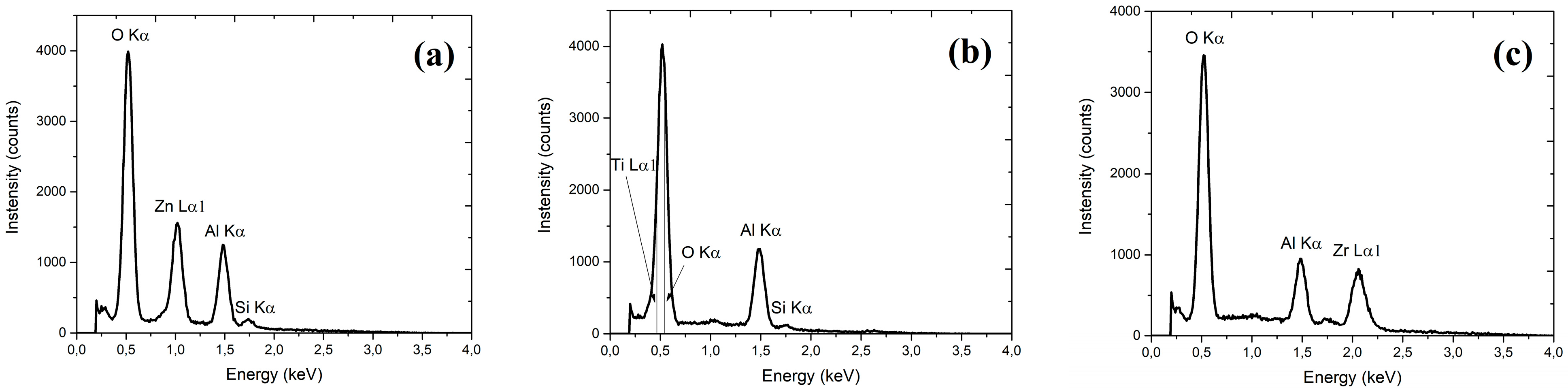
3.1. SEM and Chemical Structure of Layers

SEM cross section images were measured for all alloys prepared. The one of an Al2O3–ZnO layer deposited on silicon is shown in Figure 2. Even in this case (ZnO is an n-type material and a small Al dopant lead even to a metallic-like conductivity), an alloy with an increased AL fraction turned out to be resistive. We decided, however, not to coat layers with conducting films, which may not only increase the quality of the picture but also could affect the accuracy of thickness determination, which is crucial for these investigations. Based on the cross-section image, the thickness of all layers was determined. Layer thicknesses determined from SEM were used as starting values in modelling the results of ellipsometric measurements.
SEM images indicate (see the one shown in Figure 2) good uniformity of the obtained alloys, with very flat surfaces. For the reason already mentioned, the presented SEM images are not of high quality due to the insulating properties of the tested layers. Based on previous experiments, we avoided the sputtering of additional layers, e.g., gold or carbon, which is often used to improve the quality of images. In the case of such thin layers, it would only make it difficult to distinguish the tested layer from the sputtered one, affecting the accuracy of thickness determination.
The EDX investigations (see Table 1 and Figure 3) were performed to evaluate alloy properties—for estimation of the composition of the alloys (intended to be 50%) based on ratio n to m ALD pulses. The relevant data are collected in Table 1.
The authors realize that the EDX technique is not the best method to characterize such thin layers. The beam energy used was selected to be sufficient to generate the signal from the tested elements, but as low as possible so that the generated signal came mainly from the tested layer. In the case of using a higher voltage, a signal could be obtained from higher energy lines, but the depth of signal generation would be much greater, and the signal would come mainly from the substrate; thus, distorting the results for the layers. Having this in mind, the EDX method was used only to verify that the samples were properly prepared and contained the appropriate compounds, and the percentage results were used only as an estimation for the metals ratio. We also decided not to base on XPS or SIMS investigations. In the case of XPS, we standardly observed a huge signal due to carbon, requiring the etching of samples. For SIMS studies, we usually using much thicker samples.

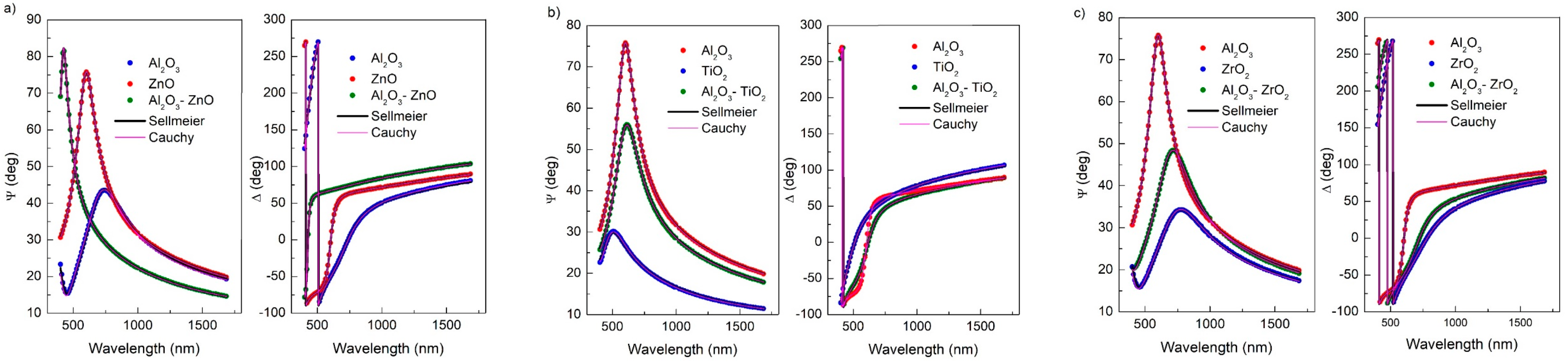
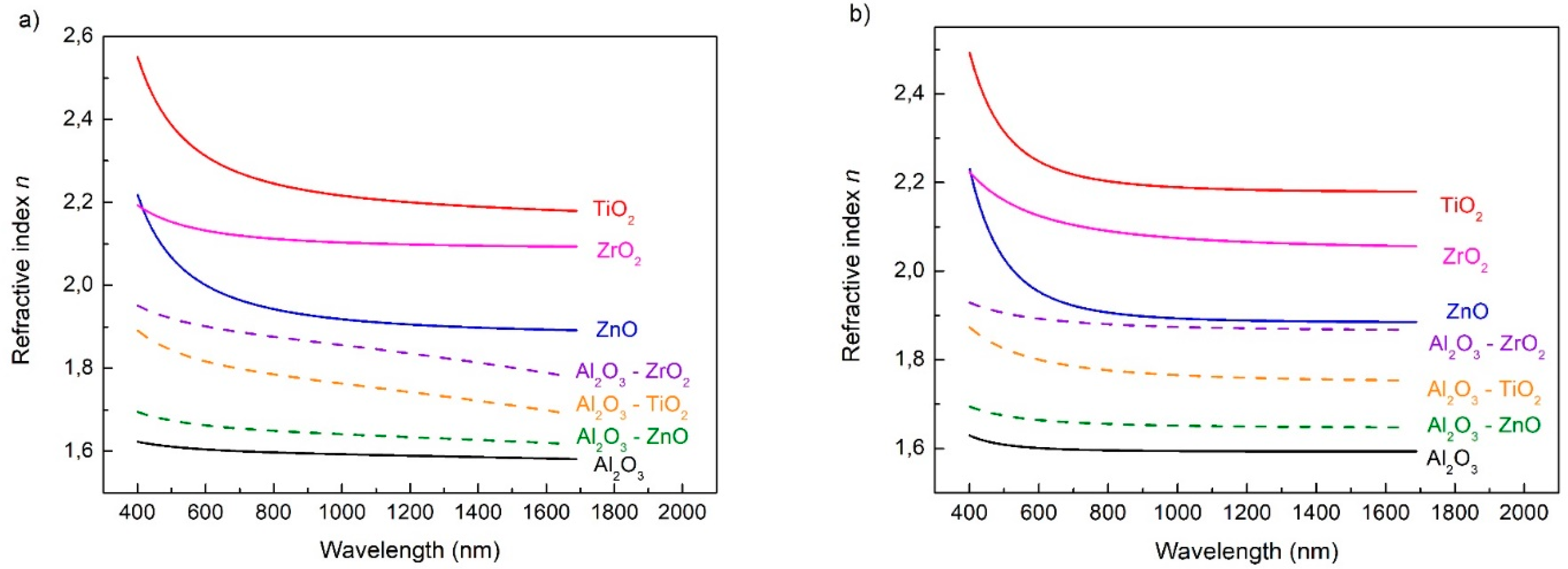
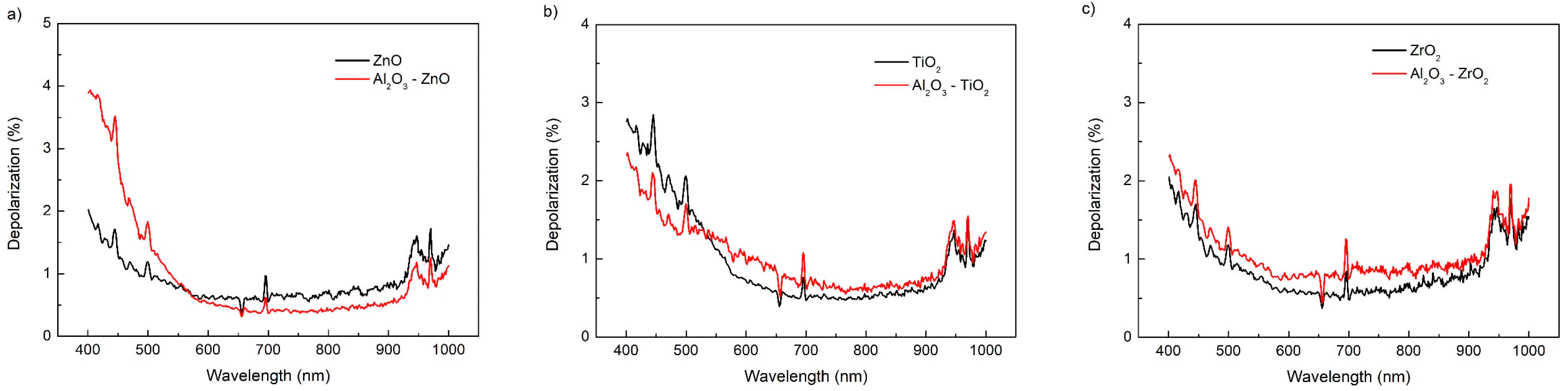
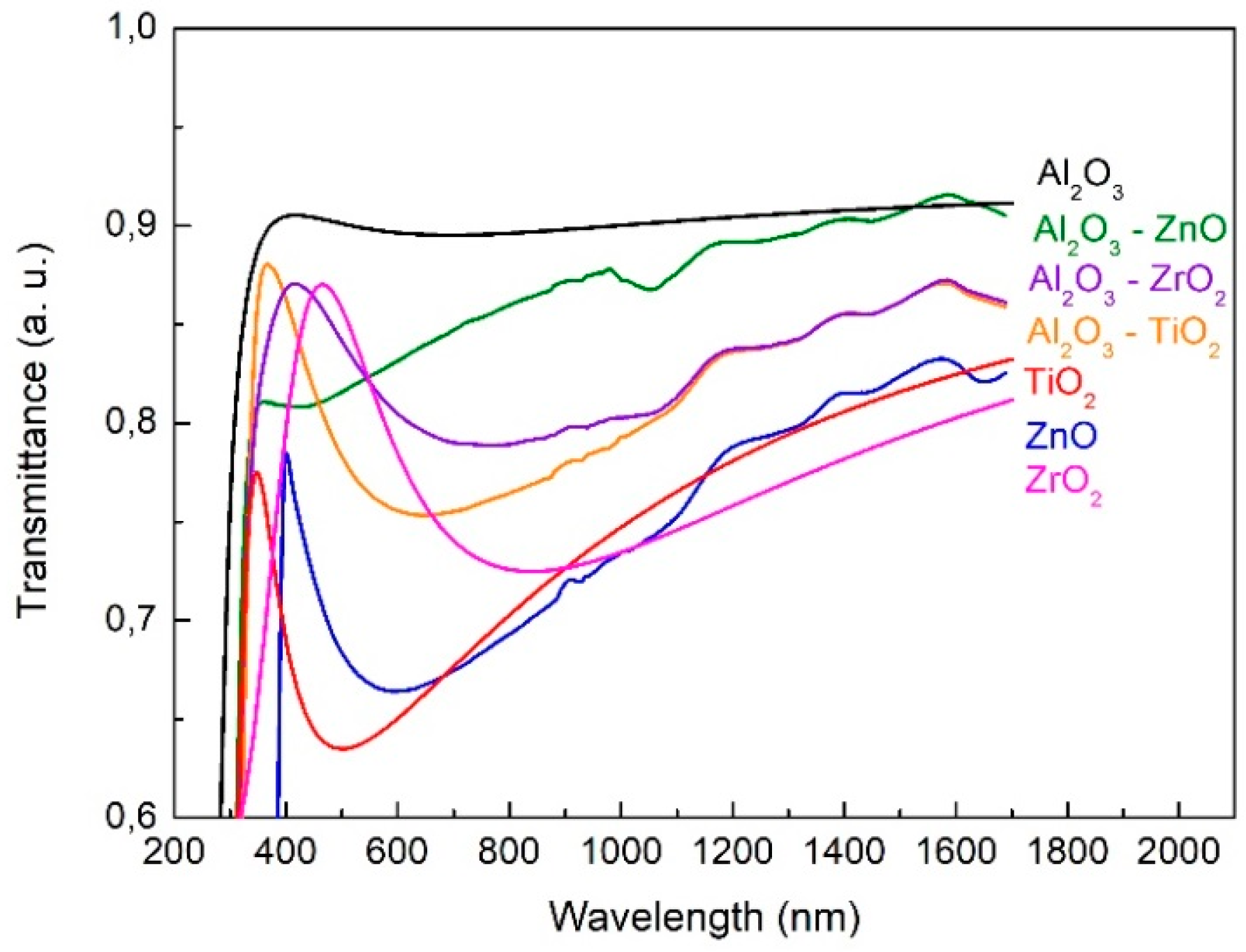
3.2. Optical Studies

SE measurements of Ψ and Δ angles were performed for all samples at an angle of light incidence on the sample of 70°. The data were analysed using CompleteEASE 5.15 software. The dispersion relations of the Ψ and Δ, as well as the fitted Sellmeier and Cauchy models for layers on a silicon substrate, are shown in Figure 4.
As can be seen in Figure 4, both models used in the presented range of wavelengths nearly completely overlap and are indistinguishable in the spectral dependences of ellipsometric angles Ψ and Δ. The mean squared errors (MSE) determined using the Levenberg–Marquardt method were low. For short wavelengths, below 400 nm, the models do not overlap themselves. This is caused by the presence of weak absorption in this region. The spectral range of the J. A. Woollam M-2000 ellipsometer enables measurements from 192 nm, but we have not analysed the results in the UV region due to the occurrence of absorption in this area. We consider only the spectral range where the layers are transparent, due to their potential use as anti-reflection filters.
Dispersion dependencies of refractive indices for layers without Al2O3 and with the addition of Al2O3 are presented in Figure 5. It is noticeable that the refractive indices of the layers with the addition of Al2O3 take intermediate values between those for pure ZnO, TiO2 and ZrO2 layers and the pure Al2O3 layer, i.e., n Z n O > n m i x > n A l 2 O 3 . The resultant value of n is the average value of the dispersion of the refractive index of the oxides constituting the layer. The determined n values for two-component layers obviously depend on the volume ratios of the oxides constituting the layer.
If we assume the occurrence of weak absorption in the VIS region, the experimental results can be fitted with the Cauchy model. Additionally, losses in directional reflection and transmission are due to the scattering of light by surface irregularities and density variations. The extinction coefficient k is negligibly small in the presented spectral region; therefore, we have not presented the dispersion relation k(λ). The Cauchy and Sellmeier dispersion models in the VIS region give almost the same results, but the differences become visible only in the near infrared.
The dispersion dependencies of the refractive index modelled by Sellmeier and Cauchy are presented in Figure 6. The Bruggeman model for mixed oxides Al2O3–ZnO, Al2O3–ZrO2 and Al2O3–TiO2 are also presented in Figure 6.
The refractive index of two-component layers in the EMA theory can be determined using the Maxwell–Garnett EMA or Bruggeman EMA model. For layers with a relatively low content of dopant, the Maxwell–Garnett EMA model is applied, as we have presented in previous work [24]. In this work, the content of Al2O3 in ZnO, TiO2 and ZrO2 oxides is relatively high The average refractive index for a mixture of two dielectric materials (with known values of refractive indices) with similar content in the layer can be calculated using the Bruggeman EMA model. In Figure 5, it can be seen that the dispersion dependencies of the refractive index for Al2O3–ZrO2 and Al2O3–TiO2 obtained as a result of modelling with the Cauchy and Bruggeman models have similar shapes and values. However, in the case of ZnO, the dispersion curve obtained as a result of applying the Bruggeman model corresponds with the curve obtained using the Sellmeier model. Volume percentages used in the Bruggeman EMA model were calculated from the EDX analysis and the results are listed in Table 2.
The light depolarisation after reflection is determined directly from ellipsometric measurements. The depolarisation coefficient describes the degree of coherence of light in the layer. The depolarisation spectra of pure broadband oxide layers and layers with Al2O3 are presented in Figure 7.
The depolarisation coefficient describes the quality of the interfaces between the air and the layer and between the layer and the substrate. For wavelengths longer than 1000 nm, the depolarisation coefficient is nearly 0%, while in the range of 400–1000 nm, the depolarisation of the alloy layers is about 0.5% higher than of the layers without the addition of Al2O3. The exception is ZnO above 550 nm. This means that the polarisation state of the light after reflection is similar for the broadband oxide layers and the alloys. There is no quantitative or qualitative change in the morphology of pure and mixed layers, which can be seen from the similarity in the shape of the depolarisation dispersion curves. A low depolarisation coefficient does not affect the choice of the optical model. The addition of Al2O3 has a small influence on the depolarisation and, thus, on the diffusion scattering from the layers. The depolarisation coefficient should be taken into account in modelling anti-reflective layers.
Transmission spectra obtained from SE for all layers are shown in Figure 8. The presence of Al2O3 increases the transparency of mixed layers, which is clearly visible in the range of about 400–1000 nm, i.e., beyond the absorption range.
Layer thicknesses and refractive indices were determined using the Cauchy and Sellmeier models. The results for three selected wavelengths are presented in Table 2. The determined layer thicknesses and refractive indices values were obtained using the application of both models. A more significant difference in refractive indices values appears for wavelengths longer than 1000 nm. This is due to differences in the applied models.

4. Conclusions

In this paper, the results of an optical study of thin layers of ZnO, ZrO2 and TiO2 broadband oxides doped/alloyed with Al2O3 grown using the atomic layer deposition technique have been presented. Without any optimisation alloys with large metal fractions were investigated. The Sellmeier and Cauchy models were used to determine the dispersion dependencies of the refractive index of single oxide layers and for two-component layers.
The addition of Al2O3 to broadband oxides (ZnO, ZrO2 and TiO2) reduces the refractive index of the alloy layers compared to the layer without the admixture. By appropriate selection of the volume percentage of Al2O3 in the layer, it is possible to design layers with new intermediate values of the refractive index. This is a highly important result opening chances for optical properties engineering.
The Bruggeman effective medium approximation model was used to determine the refractive indices without the need to measure thin alloy layers. The refractive index values obtained using Bruggeman EMA modelling correspond to those obtained experimentally. By selecting the appropriate percentages of components (Al2O3 and broadband oxide) in the layers, we are able to design layers with a specific refractive index.
Using the Fresnel equations, we can design efficient anti-reflective layers. There is no absorption observed in the presented layers; therefore, the layers with content of Al2O3 have excellent dielectric properties. The depolarisation of the beam reflected from the layers is low, nearly the same as for the undoped broadband oxide layers, which proves their high optical quality. The ability of the controlled influence to changes of the refractive indices of thin layers of ZnO, ZrO2 and TiO2 by doping with Al2O3 enables the creation of anti-reflective layers and filters.

Author Contributions

Conceptualization, N.N., J.J. and M.G.; methodology, P.D.; software, N.N.; validation, P.D., M.G. and B.S.W.; formal analysis, A.S. and S.G.; investigation, A.S. and N.N.; resources M.G. and B.S.W.; data curation, N.N. and S.G.; writing—original draft preparation, N.N., M.J.-S., M.G. and J.J.; writing—review and editing, N.N., J.J. and B.S.W.; visualization, N.N., A.V. and Ł.W.; supervision, M.G.; project administration, J.J. and M.G.; funding acquisition, M.G. and B.S.W. All authors have read and agreed to the published version of the manuscript.

Funding

This research was partially funded by the National Centre for Research and Development, grant number POIR.04.01.04-00-0052/20-00.

Institutional Review Board Statement

Not applicable.

Informed Consent Statement

Not applicable.

Data Availability Statement

Not applicable.

Conflicts of Interest

The authors declare no conflict of interest.

References

  1. Zahid, A.M.; Khokhar, M.Q.; Park, S.; Hussain, S.Q.; Kim, Y.; Yi, J. Influence of Al2O3/IZO double-layer antireflective coating on the front side of rear emitter silicon heterojunction solar cell. Vacuum 2022, 200, 110967. [Google Scholar] [CrossRef]
  2. Baco, S.; Chik, A.; Yassin, F.M. Study on optical properties of tin oxide thin film at different annealing temperature. J. Sci. Technol. 2012, 4, 61–72. [Google Scholar]
  3. Lakhdari, D.; Belgherbi, O.; Lamiri, L.; Hamissi, M. Electrochemical, structural, and optical properties of SnO2 thin films. In Proceedings of the 5ème Conférence Internationale des Energies Renouvelables (CIER-2017), Proceeding of Engineering and Technology-PET, Sousse, Tunisia, 20–22 December 2017; Volume 28, pp. 65–69. [Google Scholar]
  4. Ma, C.; Zhao, C.; Fan, X.; Liu, Z.; Liu, J. Preparation of non-stoichiometric Al2O3 film with broadband antireflective by magnetron sputtering. Chem. Phys. Lett. 2021, 764, 138229. [Google Scholar] [CrossRef]
  5. Shi, S.; Qian, S.; Hou, X.; Mu, J.; He, J.; Chou, X. Structural and optical properties of amorphous Al2O3 thin film deposited by Atomic Layer Deposition. Adv. Condens. Matter Phys. 2018, 2018, 7598978. [Google Scholar] [CrossRef]
  6. Fullagera, D.B.; Boreman, G.D.; Ellinger, C.D.; Hofmann, T. Broadband optical properties of aluminum zinc oxide thin films prepared by spatial atomic layer deposition. Thin Solid Films 2018, 653, 267–273. [Google Scholar] [CrossRef]
  7. Fouad, S.S.; Parditka, B.; Nabil, M.; Baradács, E.; Negm, S.; Atyia, H.E.; Erdélyi, Z. Bilayer number driven changes in polarizability and optical property in ZnO/TiO2 nanocomposite films prepared by ALD. Optik 2021, 233, 166617. [Google Scholar] [CrossRef]
  8. Asiltürk, M.; Burunkaya, E.; Sayılkan, F.; Kiraz, N.; Arpaç, E. Structural and optical properties of thin films prepared from surface modified ZrO2. J. Non-Cryst. Solids 2011, 357, 206–210. [Google Scholar] [CrossRef]
  9. Khan, S.B.; Zhang, Z.; Lee, S.L. Annealing influence on optical performance of HfO2 thin films. J. Alloys Compd. 2020, 816, 152552. [Google Scholar] [CrossRef]
  10. Barbos, C.; Blanc-Pelissier, D.; Fave, A.; Blanquet, A.; Crisci, A.; Fourmond, E.; Albertini, D.; Sabac, A.; Ayadi, K.; Girard, P.; et al. Characterization of Al2O3 thin films prepared by thermal ALD. Energy Procedia 2015, 77, 558–564. [Google Scholar] [CrossRef]
  11. Ponmudi, S.; Sivakumar, R.; Sanjeeviraja, C. Effects of sputtering power and substrate temperature on the optical properties of Al2O3:Cr2O3 thin films. Mater. Today Proc. 2019, 9, 193–198. [Google Scholar] [CrossRef]
  12. Groner, M.D.; Fabreguette, F.H.; Elam, J.W.; George, S.M. Low-temperature Al2O3 Atomic Layer Deposition. Chem. Mater. 2014, 16, 639–645. [Google Scholar] [CrossRef]
  13. Medjaldi, F.; Bouabellou, A.; Bouachiba, Y.; Taabouche, A.; Bouatia, K.; Serrar, H. Study of TiO2, SnO2 and nanocomposites TiO2:SnO2 thin films prepared by sol-gel method: Successful elaboration of variable—Refractive index systems. Mater. Res. Express 2020, 7, 016439. [Google Scholar] [CrossRef]
  14. Erken, Ö.; Gümüş, C. Determination of the thickness and optical constants of polycrystalline SnO2 thin film by envelope method. Adıyaman Univ. J. Sci. 2018, 8, 141–151. [Google Scholar]
  15. Koutavarapu, R.; Manepalli, R.K.N.R.; Madhav, B.T.P.; Satyanarayana, T.; Nagarjuna, G.; Shim, J.; Rao, M.C. Optical, electrical and photoluminescence studies on Al2O3 doped PVA capped ZnO nanoparticles for optoelectronic device application. Optik 2020, 205, 164236. [Google Scholar] [CrossRef]
  16. Salman, S.H.; Shihab, A.A.; Elttayef, A.-H.K. Studying the effect of the type of substrate on the structural, morphology and optical properties of TiO2 thin films prepared by RF magnetron sputtering. Energy Procedia 2019, 157, 199–207. [Google Scholar] [CrossRef]
  17. Yusoh, R.; Horprathum, M.; Eiamchai, P.; Chindaudom, P.; Aiempanakit, K. Determination of optical and physical properties of ZrO2 films by spectroscopic ellipsometry. Procedia Eng. 2012, 32, 745–751. [Google Scholar] [CrossRef]
  18. Prieto-Lopez, L.O.; Yubero, F.; Machorro, R.; De La Cruz, W. Optical properties of Zr and ZrO2 films deposited by laser ablation. Microelectron. J. 2008, 39, 1371–1373. [Google Scholar] [CrossRef]
  19. Chung, N.T.K.; Dang, H.P.; Nguyen, T.P.; Le, T. Effects of Zn and Zn–N doping on optical, electrical, and structural properties of p-type SnO2 films. J. Photochem. Photobiol. A 2021, 418, 113436. [Google Scholar] [CrossRef]
  20. Abu Sayeed, M.; Rouf, H.K. Al-doped SnO2 thin films: Impacts of high temperature annealing on the structural, optical and electrical properties. J. Mater. Res. Technol. 2021, 15, 3409–3425. [Google Scholar] [CrossRef]
  21. Ching, W.Y.; Xu, Y.-N. First-Principles calculation of electronic, optical, and structural properties of α-Al2O3. J. Am. Ceram. Soc. 1994, 77, 404–411. [Google Scholar] [CrossRef]
  22. Wójcik, A.; Kopalko, K.; Godlewski, M.; Guziewicz, E.; Jakieła, R.; Minikayev, R.; Paszkowicz, W. Magnetic properties of ZnMnO films grown at low temperature by atomic layer deposition. Appl. Phys. Lett. 2006, 89, 051907. [Google Scholar] [CrossRef]
  23. Sawicki, M.; Guziewicz, E.; Lukasiewicz, M.I.; Proselkov, O.; Kowalik, I.A.; Lisowski, W.; Dłużewski, P.; Wittlin, A.; Jaworski, M.; Wolska, A.; et al. Homogeneous and heterogeneous magnetism in (Zn,Co)O: From a random antiferromagnet to a dipolar superferromagnet by changing the growth temperature. Phys. Rev. B 2013, 88, 085204. [Google Scholar] [CrossRef]
  24. Nosidlak, N.; Jaglarz, J.; Dulian, P.; Pietruszka, R.; Witkowski, B.S.; Godlewski, M.; Powroźnik, W.; Stapiński, T. The thermo-optical and optical properties of thin ZnO and AZO films produced using the atomic layer deposition technology. J. Alloys Compd. 2022, 900, 163313. [Google Scholar] [CrossRef]
  25. Tompkins, H.G.; McGahan, W.A. Spectroscopic Ellipsometry and Reflectometry: A User’s Guide; John Wiley & Sons, Inc.: New York, NY, USA, 1999. [Google Scholar]
  26. Azzam, R.M.A.; Bashara, N.M. Ellipsometry and Polarized Light; North-Holland: Amsterdam, The Netherlands, 1987. [Google Scholar]
  27. Woollam, J.A. CompleteEASE™ Data Analysis Manual; JA Woollam Co., Inc.: Lincoln, NE, USA, 2009. [Google Scholar]
  28. Sellmeier, W. Ueber die durch die Aetherschwingungen erregten Mitschwingungen der Korpertheilchen und deren Ruckwirkung auf die ersteren, besonders zur Erklarung der Dispersion und ihrer Anomalien. Ann. Phys. Chem. 1872, 223, 386–403. [Google Scholar] [CrossRef]
  29. Aspnes, D.E.; Theeten, J.B.; Hottier, F. Investigation of effective-medium models of microscopic surface roughness by spectroscopic ellipsometry. Phys. Rev. B 1979, 20, 3292–3302. [Google Scholar] [CrossRef]
Figure 2. Cross section SEM image of an Al2O3–ZnO layer.
Coatings 13 01872 g002
Figure 3. Results of the EDX investigations of three types of alloys: Al2O3–ZnO (a), Al2O3–TiO2 (b) and Al2O3–ZrO2 (c).
Coatings 13 01872 g003
Figure 4. Spectral dependence of ellipsometric angles Ψ and Δ at an incidence angle of 70° for: (a) Al2O3–ZnO, (b) Al2O3–TiO2 and (c) Al2O3–ZrO2 layers on a silicon substrate, including Sellmeier and Cauchy models.
Coatings 13 01872 g004
Figure 5. Spectral dependencies of refractive indices determined using the (a) Sellmeier and (b) Cauchy models.
Coatings 13 01872 g005
Figure 6. Dispersion relations of refractive indices received as a result of modelling with Sellmeier, Cauchy and Bruggeman models.
Coatings 13 01872 g006
Figure 7. Depolarisation spectra of: (a) ZnO and Al2O3–ZnO, (b) TiO2 and Al2O3–TiO2, and (c) ZrO2 and Al2O3–ZrO2.
Coatings 13 01872 g007
Figure 8. Transmission spectra of Al2O3, ZnO, TiO2, ZrO2, Al2O3–ZnO, Al2O3–TiO2, Al2O3–ZrO2 layers.
Coatings 13 01872 g008
Table 1. EDX results of the investigated alloys.
Al2O3–ZnOAl%O%Zn%Al/Zn
-1968131.46
Al2O3–TiO2Al%O%Ti%Al/Ti
-1256320.375
Al2O3–ZrO2Al%O%Zr%Al/Zr
-1273150.8
Table 2. Thin-layer thicknesses and refractive indices obtained using the Sellmeier and Cauchy models, refractive indices obtained from Bruggeman EMA and weight percentages of Al2O3 in mixed layers.
Thin Layer on SiAl2O3TiO2ZrO2ZnOAl2O3–TiO2Al2O3–ZrO2Al2O3–ZnO
SellmeierThickness (nm)116591041089911076
n400 nm1.6232.5502.1932.2181.9811.9511.695
n632 nm1.6002.2972.1301.9861.8101.8961.659
n900 nm1.5932.2282.1071.9281.7741.8661.645
CauchyThickness (nm)1166110511111010076
n400 nm1.6292.4922.2232.2291.8731.9291.694
n632 nm1.6002.2352.1181.9491.7951.8901.662
n900 nm1.5952.1942.0811.8981.7701.8771.653
Bruggemann632 nm----1.8021.8911.657
% of Al2O3100---323654
Disclaimer/Publisher’s Note: The statements, opinions and data contained in all publications are solely those of the individual author(s) and contributor(s) and not of MDPI and/or the editor(s). MDPI and/or the editor(s) disclaim responsibility for any injury to people or property resulting from any ideas, methods, instructions or products referred to in the content.

