Article

Internal Diameter Atmospheric-Plasma-Sprayed High-Performance YSZ-Based Thermal Barrier Coatings

1
Key Laboratory of Pressure System and Safety, Ministry of Education, East China University of Science and Technology, Shanghai 200237, China
2
Shanghai Institute of Aircraft Mechanics and Control, Shanghai 200092, China
*
Author to whom correspondence should be addressed.
Coatings 2023, 13(11), 1868; https://doi.org/10.3390/coatings13111868
Submission received: 10 October 2023 / Revised: 23 October 2023 / Accepted: 24 October 2023 / Published: 31 October 2023

Abstract

:
Thermal barrier coatings (TBCs) play a crucial role in enhancing the operating temperature of key equipment. However, when TBCs are sprayed on the internal surface of these components, there are issues related to the imperfect internal diameter atmospheric plasma spray (ID-APS) process and the unsatisfactory performance of TBCs in internal holes. Yttria-stabilized zirconia (YSZ), YSZ + Gadolinium zirconate (GZ) and YSZ + tantalate (RETaO4) TBCs were prepared using the SM F210 ID-APS gun. The thermal shock and particle erosion resistance of the coatings were compared, and the relationship between the structure and properties was investigated. The results show that the hardness, fracture toughness and erosion resistance of the three coatings are the largest in the YSZ coating and the smallest in the GZ coating. YSZ coating also has the best thermal shock resistance. These research findings have important guiding significance for the improvement of the ID-APS process.

1. Introduction

Thermal barrier coating (TBC) is generally composed of ceramic layer, bonding coat and thermally grown oxides (TGO) formed during high-temperature operation, offering excellent thermal insulation performance [1]. Critical equipment such as engine cylinders and combustors [2,3,4] frequently operate in prolonged high-temperature environment. TBCs need to be applied to the internal surface of cylinder bodies, pipelines and other components to enhance operating temperature and performance [5,6,7]. One of the most common preparation methods for TBCs is atmospheric plasma spray (APS) [8]. However, traditional APS can only prepare shallow internal surface coatings through off-angle spraying [9]. Therefore, specialized internal diameter atmospheric plasma spray (ID-APS) process is required.
The narrow spray space of internal holes poses higher requirements for the spraying process. In such confined space, lower cooling results in elevated heat accumulation and oxidation, causing lower bonding strength [10,11]. Enhancing the spray distance is an effective solution [12]. However, the adjustability of the spray distance for ID-APS is limited. Furthermore, the mismatch in the rotational speed of the spray gun and equipment can cause uneven coating thickness [13], and excessive dust will be redeposited within coatings, adversely affecting adhesion strength and porosity [14,15]. To address these issues, using a specialized ID-APS gun with a smaller nozzle in a narrow space is necessary [16].
SM F100 and SM F210 are two commonly used ID-APS guns for internal spraying [9,17,18,19,20]. However, the SM F100 gun has a minimum spray internal diameter of 100 mm, while that of the SM F210 gun is 60 mm, making it suitable for a broader range of applications. The SM F210 gun has been used for preparing wear-resistant and corrosion-resistant coatings, exhibiting good density and bonding strength [17,19,21,22]. However, its usage in TBC preparation is relatively limited. Thus, exploring suitable SM F210 spray parameters is an effective approach for improving the performance of ID-APS coatings.
YSZ, a commonly used material for the ceramic layer, undergoes phase transformation and sintering when exposed to temperatures above 1200 °C for a long time. These changes lead to volume expansion stress due to phase transformation and porosity reduction due to sintering, resulting in decreased strain tolerance and crack propagation failure [23,24,25,26,27,28,29]. Therefore, materials that can operate at higher temperatures and have better phase stability need to be explored, considering their crystal structure, thermal conductivity and thermal expansion coefficient. Gadolinium zirconate (Gd2Zr2O7, GZ) [30,31] and tantalate (RETaO4) [32,33] are potentially suitable ceramic layer materials.
The crystal structure of GZ is pyrochlore containing oxygen vacancies, resulting in low thermal conductivity [34,35,36]. Pyrochlore transforms into fluorite around 1530 °C without significant volume changes and has good phase stability at high temperatures [37]. However, its thermal expansion coefficient is lower compared to YSZ [34], and GZ lacks toughening mechanism and has a low fracture toughness. During high-temperature operation, GZ can react with TGO, affecting thermal shock resistance and the overall life of coatings [38].
Tantalate crystal initially forms an m′ phase and remains stable at low temperature. It transforms into a t phase at approximately 1450 °C and then undergoes ferroelastic phase transformation to an m phase when cooling to about 1430 °C. During t–m phase transformations, there are almost no volume changes, effectively enhancing high-temperature toughness [39]. The complex crystal structure and large radius of RE ions result in low thermal conductivity. However, its thermal expansion coefficient is low compared to YSZ and varies significantly with temperature [40,41]. To ensure that TBCs maintain integrity during thermal shock, the double-ceramic-layer (DCL) structure has been experimented with. A low thermal conductivity material is used as the top layer, with YSZ acting as a transition layer. This structure helps reduce thermal expansion mismatch stress between the top layer and the bonding coat and mitigates the phase transformation and sintering of YSZ, consequently improving thermal shock resistance and the life of TBCs [42,43,44].
There have been several attempts to prepare GZ coatings on the surface of YSZ coatings to improve the thermal shock resistance of TBCs. Studies have shown that DCL structure has superior thermal shock resistance compared to single GZ TBCs [44,45,46,47]. However, the improvement in life is not significant compared to single YSZ TBCs above 1400 °C. This indicates the need for further improvements in porosity and interface bonding strength [48,49]. On the other hand, there have been few investigations into the preparation of tantalate coatings on YSZ coatings. Single tantalate coatings have been prepared, and their properties, such as thermal shock resistance, were measured [50]. The application and failure mechanisms at higher temperatures require further analysis. Additionally, the application of DCL coatings in the ID-APS process is limited, so more research is needed to develop appropriate preparation process.
In this study, the SM F210 ID-APS gun is used to prepare GZ and tantalate coatings on the surface of YSZ coatings. A single YSZ coating serves as a reference for comparison. The primary objective of this study is to investigate the structure and performance of TBCs, focusing on thermal shock resistance, particle erosion resistance, etc. Additionally, this study aims to analyze the reasons for coating failure, providing valuable insights for further enhancing the performance of TBCs.

2. Materials and Methods

2.1. Coating Deposition

In this study, all coatings were prepared using the SM F210 ID-APS gun. Before spraying, the 3 mm thick high-temperature alloy substrate (GH3230) underwent sandblasting treatment, followed by alcohol ultrasonic cleaning. The bonding coat was prepared using commercially available NiCrAlY powder (45–106 μm, Beijing Sunspraying New Material Co., Ltd., China). For single-ceramic-layer coatings, 8YSZ powder was deposited, while for DCL coatings, the bottom layer was deposited with 8YSZ powder, and the top layer was deposited with GZ and tantalate powder. The morphologies of ceramic powders are shown in Figure 1. The composition of the coatings is summarized in Table 1. The spray parameters of each coating are summarized in Table 2. The bond layer thickness for the coatings was about 180–200 μm and the ceramic layer thickness ranged from 250–270 μm. In DCL coatings, the top layer thickness was approximately 90–100 μm, and the YSZ layer thickness was around 160–170 μm.

2.2. Mechanical Properties Measurement

The microhardness of as-sprayed coatings was measured using a Vickers hardness tester (BUEHER MICROMET5104, Akashi Corporation, Osaka, Japan). The loading load of 300 g was applied for 15 s. A total of 15 points were randomly selected on each ceramic layer to obtain the average microhardness value of coatings. Based on the indentation morphology, the fracture toughness (Gc) was calculated according to the following Equation (1) [51]:
G c = 6.115 × 10 4 × a 2 × P c 3
where a is half-diagonal length of indentation, c is half length of the crack starting from center of indentation, and P is the applied load.

2.3. Thermal Shock Test

A thermal shock test was conducted using a gas burner rig test setup (Shaanxi Dewei Automation Co., Ltd., Xi’an, China) to simulate the actual operating conditions of TBCs in the engine. The ceramic layer of TBCs was heated with a propane/oxygen flame jet and the substrate was cooled with compressed air. The temperature of the samples was monitored using a non-contact infrared thermometer (Smart Sensor Instrument Co., Ltd., Dongguan, China). During the heating stage, the sample surface was heated to 1450 °C and maintained for 2 min. In the cooling stage, compressed air was used to cool the sample surface down to 80 °C and maintained for 2 min. One thermal shock was defined as one complete heating and cooling stage. Thermal shock failure was defined as the presence of the damaged area reaching 10% of the total surface area. Thermal shock life was defined as the number of thermal shock cycles meeting the failure criterion. Each coating underwent three complete thermal shock tests, and the average life was taken as the final thermal shock life.

2.4. Particle Erosion Test

A particle erosion test was conducted using a homemade particle erosion machine at room temperature. Erosion particles were alumina particles with an average diameter of 50 μm. The erosion velocity was set at 110 m/s and 200 m/s, with an erosion angle of 90°. Before and after each erosion test, samples were ultrasonically cleaned with alcohol and then weighed using a precision balance accurate to four decimal places. The erosion rate was calculated as the ratio of the mass loss of coatings to the mass of erosion particles. Erosion of traditional APS YSZ coating was also conducted, and this erosion rate was used as a reference.

2.5. Characterization

The phase composition of the coatings was determined using an X-ray diffractometer (XRD, D/Max2550VB/PC, RIGAKU, Tokyo, Japan) with a scan rate of 10°/min, a scan step of 0.02° and a diffraction angle of 20–80°.
A metallographic polishing process was used to prepare cross-sectional samples of as-sprayed, thermal shock-failed and particle erosion-failed TBCs. A scanning electron microscope (SEM, ZEISS EVO MA15, Carl Zeiss SMT Ltd., Cambridge, UK) was used to observe the cross-sectional and surface morphology of as-sprayed and particle erosion failed coatings. The porosity of the as-sprayed coatings was determined through image analysis, which was calculated using the average of three backscattered electron images of the cross-section, at ×1000 magnification.

3. Results

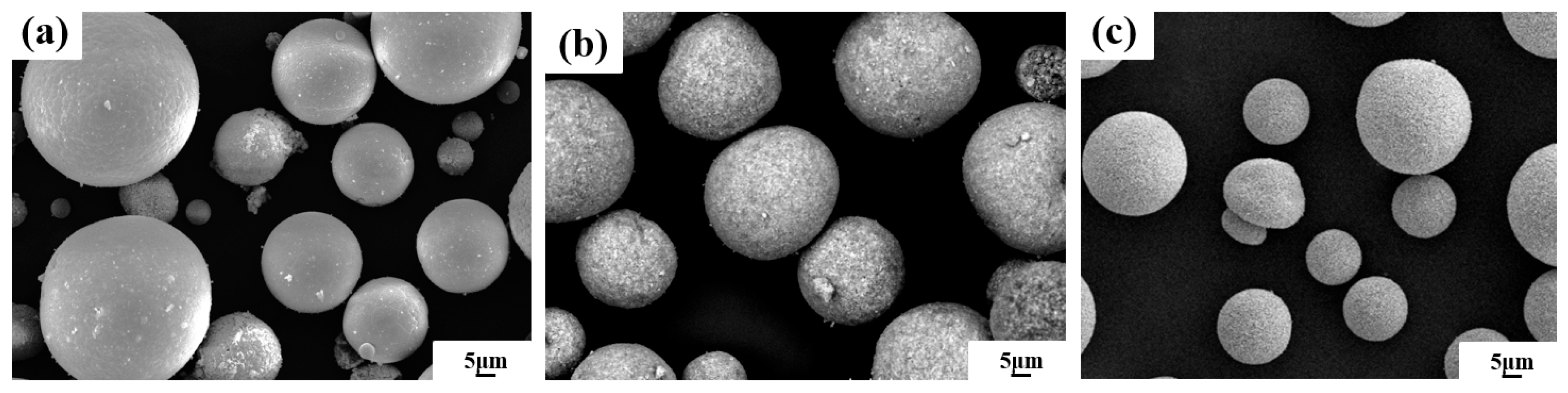
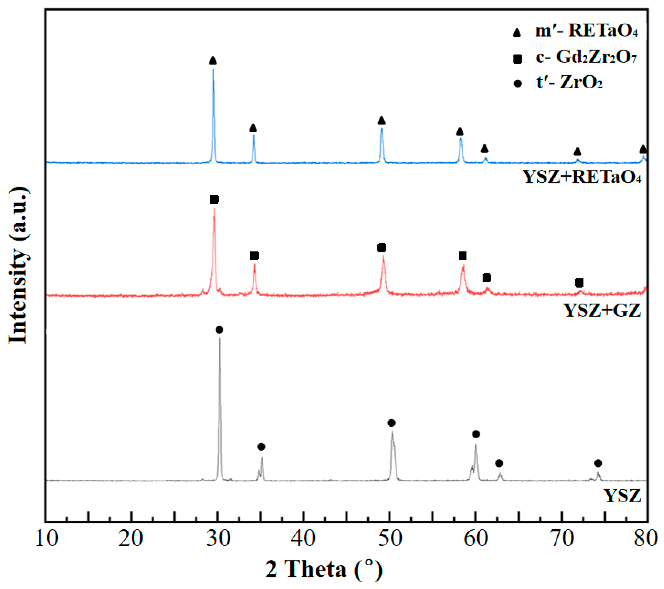
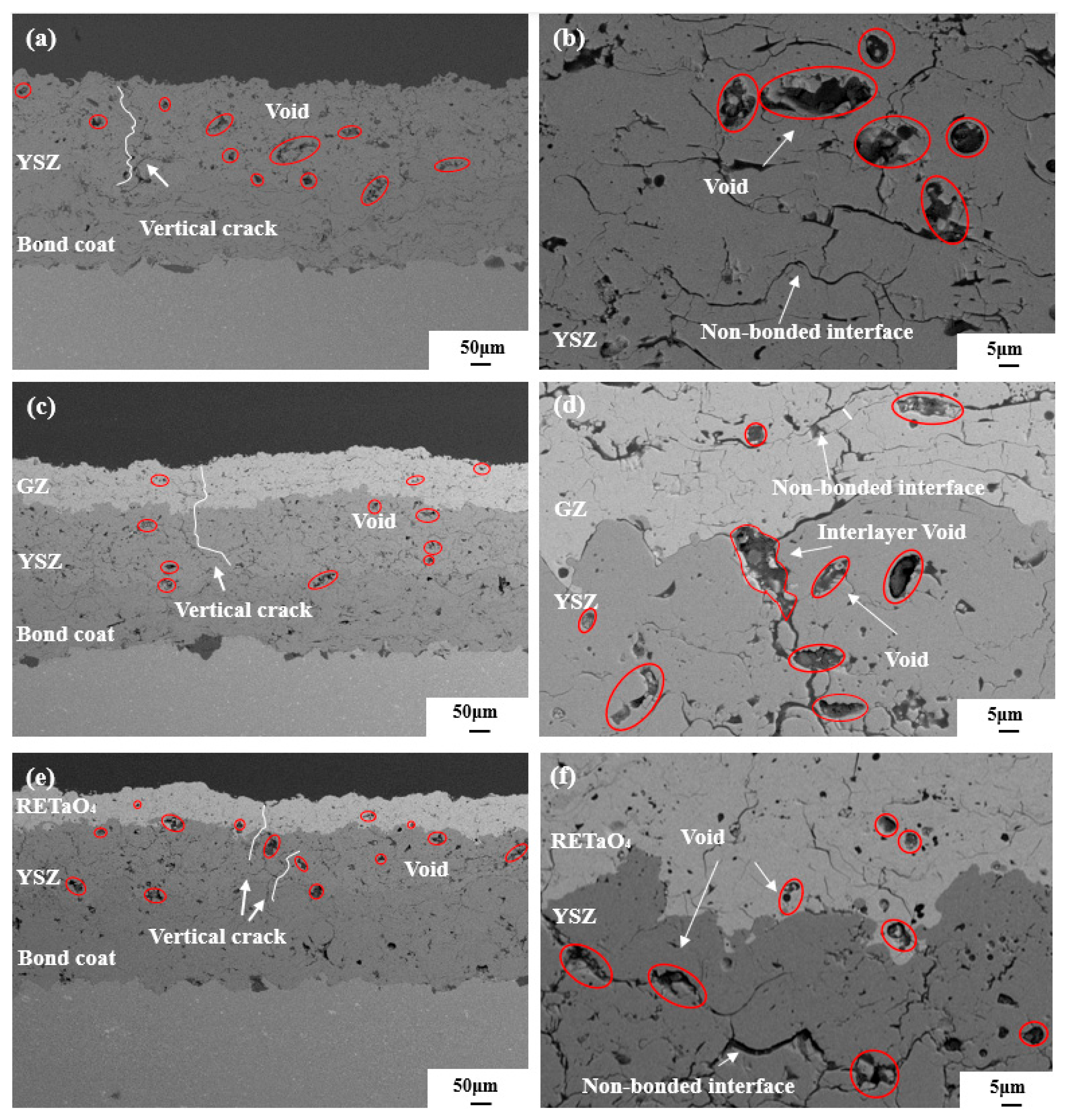
3.1. Microstructure of as-Sprayed Coatings

Figure 2 shows the phase composition of as-sprayed TBCs of YSZ, YSZ + GZ and YSZ + tantalate. YSZ crystal primarily consists of a metastable tetragonal zirconia phase with a ferroelastic phase transformation toughening mechanism [23]. GZ crystal has a pyrochlore structure with oxygen vacancies. Tantalate crystal structure exhibits an m′-RETaO4 structure which lacks the ferroelastic toughening mechanism of the m phase [39].
The cross-sectional morphologies of YSZ, YSZ + GZ and YSZ + tantalate as-sprayed TBCs are shown in Figure 3. The coatings show a typical APS lamellar structure, the ceramic layer of YSZ coating has a porosity of 11.01%, the ceramic layer of YSZ + GZ coating has a total porosity of 10.41%, the YSZ layer has a porosity of 10.86% and the GZ layer has a porosity of 9.65%. Figure 3c,d show vertical cracks throughout the GZ and YSZ layers, with overall good bonding between the two layers. The ceramic layer of YSZ + tantalate coating has a total porosity of 8.82%, the YSZ layer has a porosity of 10.17% and the tantalate layer has a porosity of 7.39%. Figure 3e,f show good interlayer bonding between tantalate and the YSZ layers.

3.2. Mechanical Properties

The Vickers hardness of YSZ, GZ and tantalate as-sprayed coatings are 791 ± 150 HV, 447 ± 105 HV and 554 ± 92 HV, respectively. Among the three coatings, the YSZ layers exhibit the highest hardness, while the GZ layer shows the lowest hardness. The fracture toughness of YSZ, GZ and tantalate as-sprayed coatings are 37.4 ± 10.1 J × m−2, 5.8 ± 1.2 J × m−2 and 19.5 ± 4.6 J × m−2, respectively. The fracture toughness of YSZ is the highest and approximately 6.5 and 1.9 times that of GZ and tantalate among the three coatings. The relative order of hardness and fracture toughness among the three coatings remains consistent, with YSZ displaying the highest values due to its ferroelastic toughening mechanism [23].

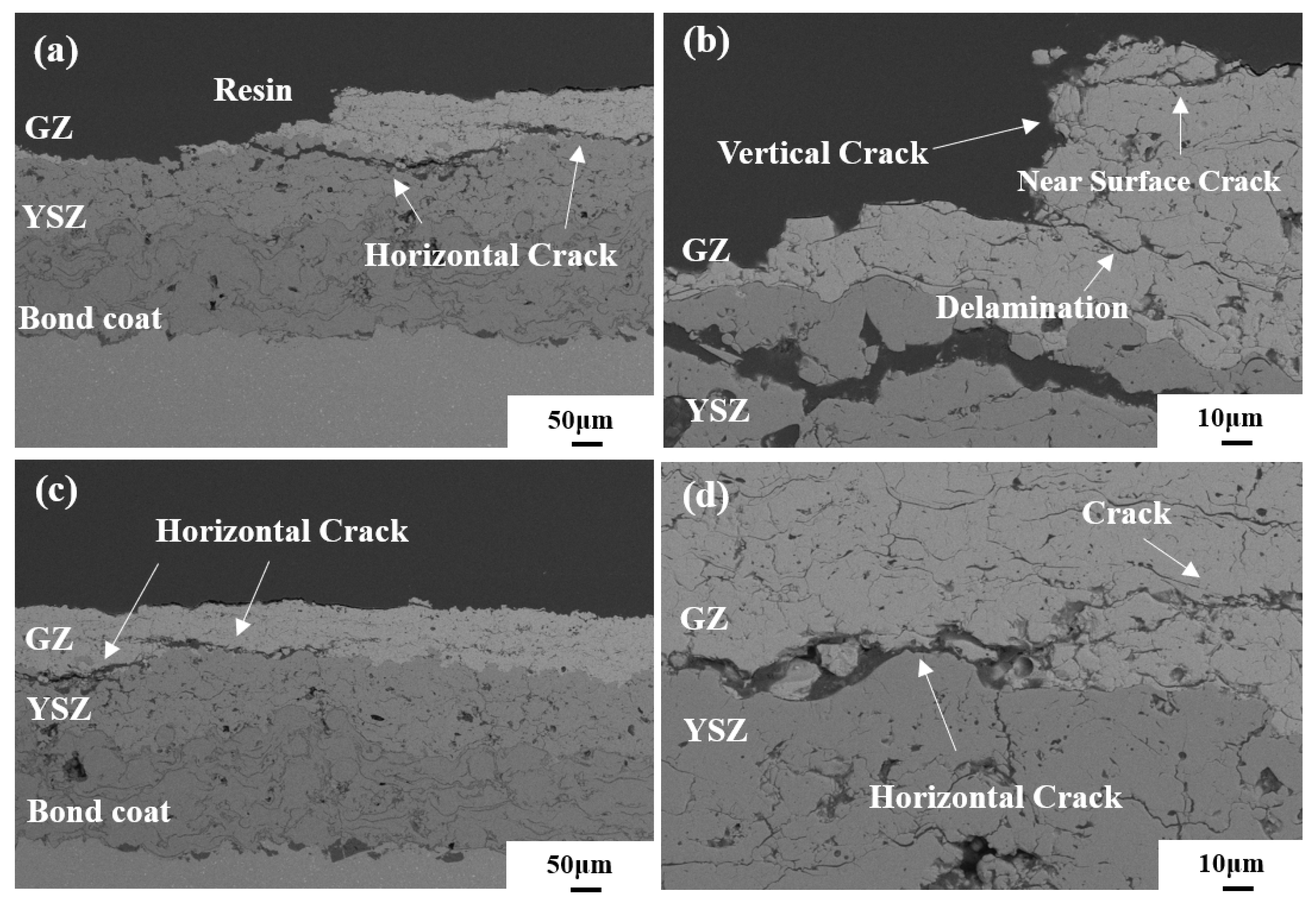
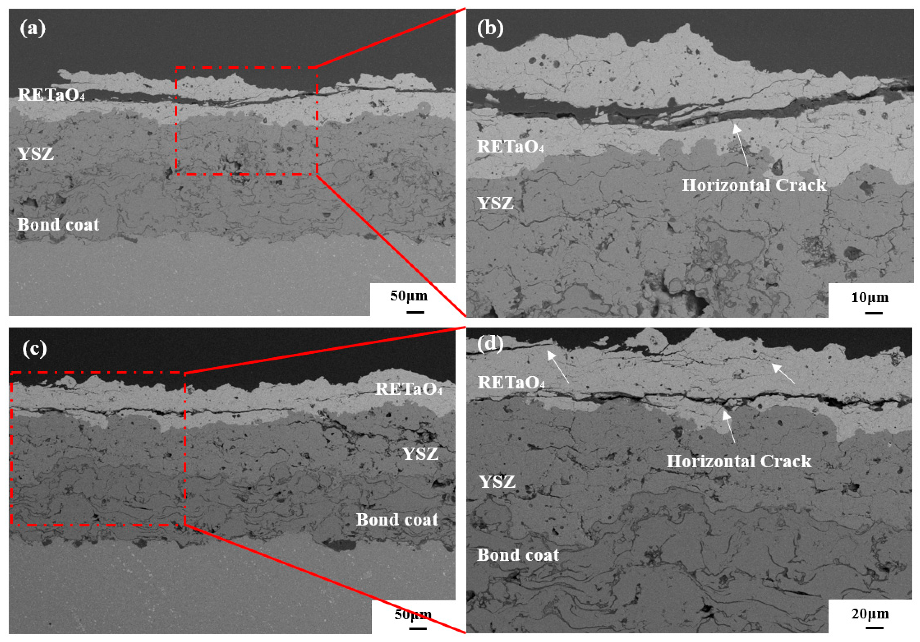
3.3. Thermal Shock Resistance

The thermal shock life of YSZ, YSZ + GZ and YSZ + tantalate TBCs is 109 ± 53 cycles, 7 ± 4 cycles and 1 cycle, respectively. YSZ TBCs demonstrate superior thermal shock resistance compared to both YSZ + GZ and YSZ + tantalate TBCs.
Figure 4 shows the cross-sectional morphologies of failed YSZ TBCs. Figure 4a shows that, due to the difference in thermal expansion coefficient between YSZ (10.7 × 10⁻⁶ K−1) and the bond coat (17.5 × 10⁻⁶ K−1) [52], horizontal cracks propagate and extend, leading to the coating’s buckling failure. In Figure 4b, horizontal cracks extend into the interior and surface of the coating due to residual thermal stresses. The crack length significantly exceeds the coating’s thickness. In Figure 4c, there is evident growth of TGO around the interface. The thermal expansion coefficient of TGO (15.3 × 10⁻⁶ K−1) [52] differs from that of YSZ and bond coat, further intensifying thermal expansion mismatch stress. Figure 3a and Figure 4d, respectively, display the cross-sectional morphology of as-sprayed and failed YSZ coatings. After thermal shock failure, pores and vertical cracks in coatings undergo sintering and shrinkage, accommodating stress accumulation and propagation of horizontal cracks [53,54]. This failure is primarily attributed to the combined effects of thermal expansion mismatch stress among YSZ, TGO and bond coat, thermal growth stress induced by TGO, and reduced strain tolerance due to sintering and phase transformation.
Figure 5 shows the cross-sectional morphologies of failed YSZ + GZ TBCs. The difference in the thermal expansion coefficient between GZ (8–10.6 × 10⁻⁶ K−1) [34] and YSZ (10.7 × 10⁻⁶ K−1), along with giant temperature differences, generates residual stresses near the interface during preparation and thermal shock in DCL coatings, making the interface prone to crack formation [55]. Figure 5a,b show that the GZ layer with a low fracture toughness (5.8 J/m2) has poor resistance to crack propagation. Vertical and horizontal cracks extend and interconnect, leading to significant delamination. Figure 5c,d show that horizontal cracks propagate within the GZ layer around the interface between YSZ and GZ. This failure can be attributed to a combination of the low fracture toughness and the thermal expansion coefficient of the GZ layer, along with the substantial residual stresses generated at the interface during preparation and thermal shock.
Figure 6 shows the cross-sectional morphologies of failed YSZ + tantalate TBCs. A notable difference in the thermal expansion coefficient between tantalate (3–8 × 10⁻⁶ K−1) [41] and YSZ (10.7 × 10⁻⁶ K−1) results in substantial interface residual stresses and thermal expansion mismatch stresses. Long horizontal cracks are formed within the tantalate layer, accompanied by a large amount of delamination. The failure can be attributed to significant residual stresses and thermal expansion mismatch stresses between the YSZ and tantalate layers.
The thermal expansion coefficient and thermal conductivity of the different layers are shown in Table 3. It can be seen that in DCL coatings, the lower thermal conductivity of GZ and tantalate may reduce the thermal expansion mismatch stress between YSZ and the bond coat, and the main reasons for coating failure are the differences in the thermal expansion coefficients between the ceramic layers and the lower fracture toughness of the top layer. As for the single YSZ coating, the primary reasons for failure are the differences in the thermal expansion coefficient among YSZ, TGO and the bonding coat, as well as the growth of TGO. During thermal shock, the combination of stress induced by the growth of TGO, the thermal expansion coefficient mismatch stress among YSZ, GZ, tantalate, TGO and the bonding coat, and the interface residual thermal stresses, lead to crack propagation and coating failure [47,54,55,56].

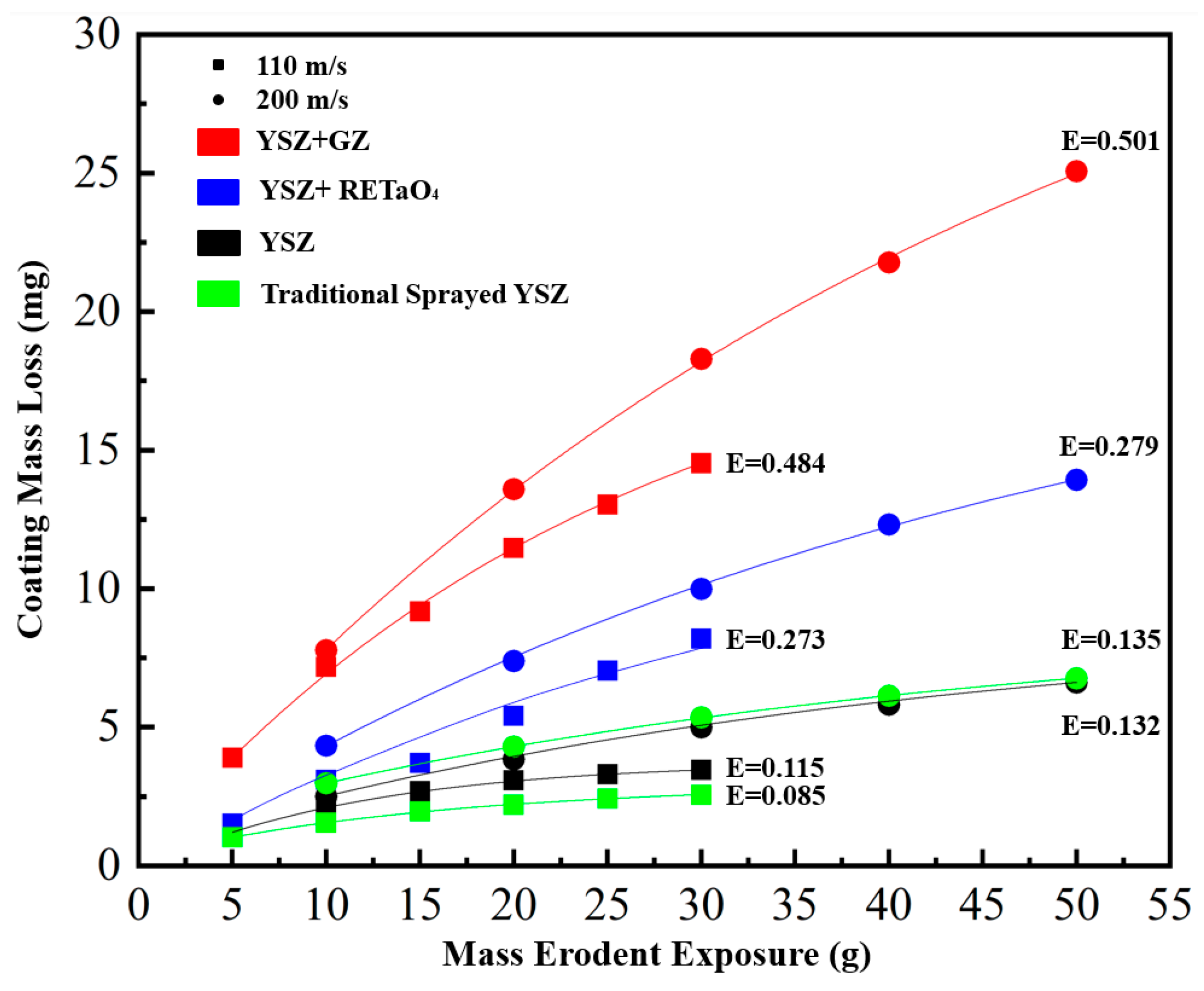
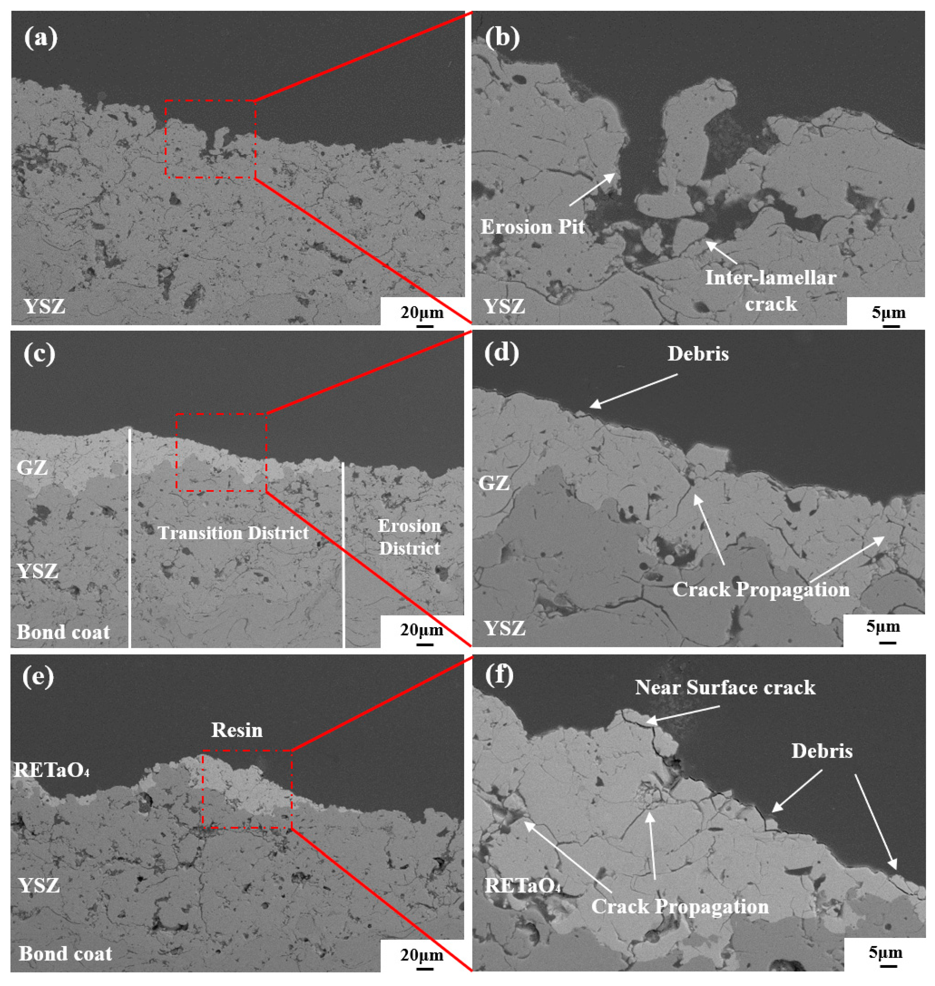
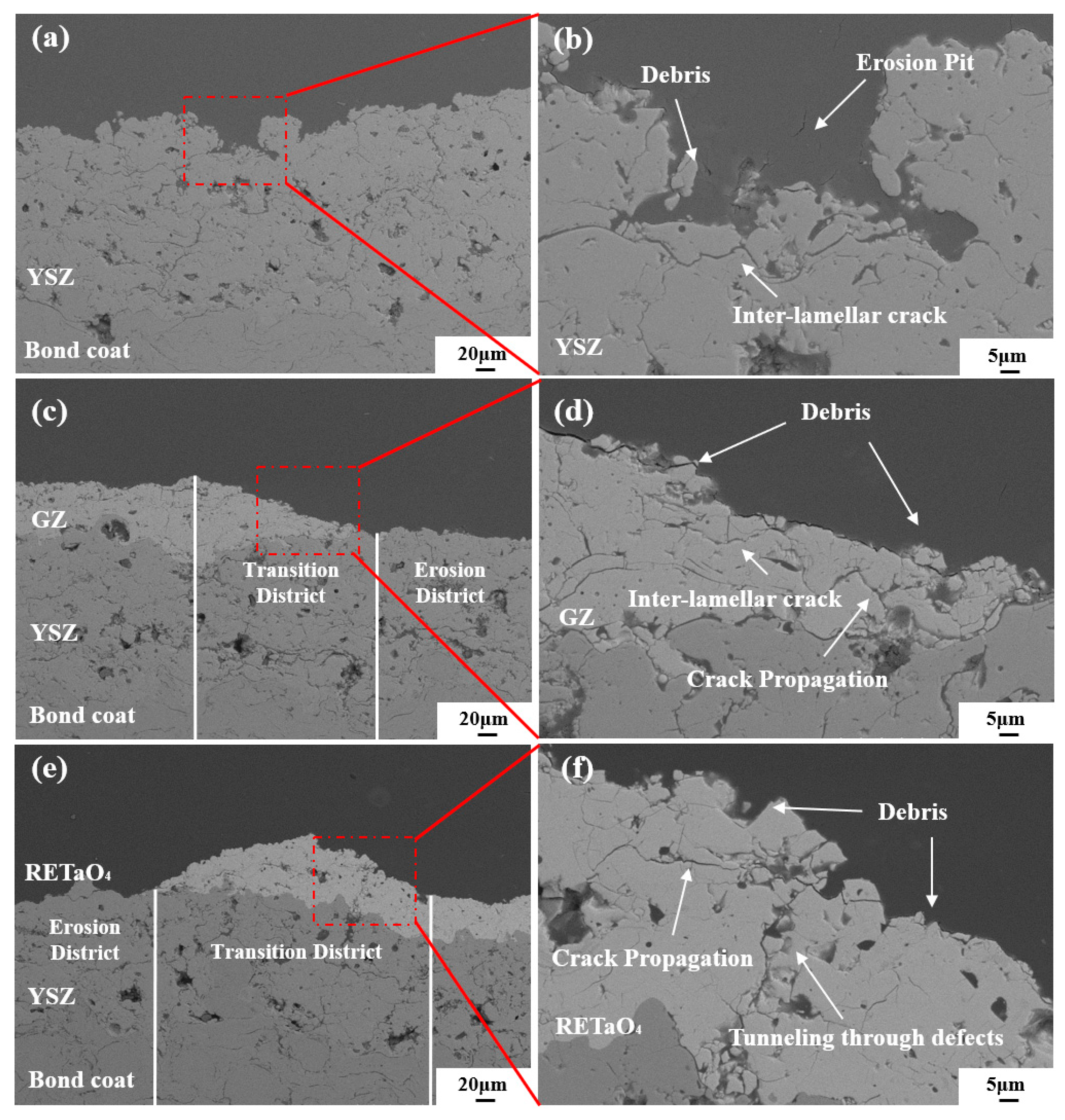
3.4. Particle Erosion Resistance

Figure 7 shows a comparison of the erosion rates at 110 and 200 m/s velocities. At 110 m/s velocity, YSZ coating has the lowest erosion rate of 0.115 mg/g, which is close to 0.085 mg/g of the traditional YSZ coating erosion rate. The YSZ + GZ coating exhibits the highest erosion rate of 0.484 mg/g. The erosion rates of the three coatings are contrary to the trends of microhardness and fracture toughness. YSZ coating exhibits the lowest erosion rate due to its highest microhardness and toughness [56]. At 200 m/s velocity, all three coatings experience a slight increase in the erosion rate compared to 110 m/s. In this study, the coatings with higher microhardness and fracture toughness demonstrate better erosion resistance, and the increase in erosion velocity has a minor effect on erosion rate.
Figure 8 shows the cross-sectional morphologies of failed YSZ, YSZ + GZ and YSZ + tantalate coatings at 110 m/s velocity. Figure 8b shows that YSZ coatings only exhibit some pits and minor extension cracks at the center of the erosion region. The high-stress impact of fast-speed particles causes the top layers to spall along interlayer cracks, while YSZ with high fracture toughness (37.4 J/m2) prevents further crack propagation into the interior of coatings. Figure 8c,d show that the GZ layer with a lower fracture toughness (5.8 J/m2) completely delaminates under the impact of high-energy particles at the erosion center. The transition district between the GZ and YSZ layers shows a smooth surface with fragments peeling off and connections between cracks and pores. In contrast, the YSZ layer, with a higher fracture toughness does not exhibit significant delamination. The special fracture morphology of GZ coating is related to its low fracture toughness. Under the effects of particle erosion, cracks spread inside the coating rather than along the non-bonded interface in coatings, resulting in the occurrence of a smooth surface. Figure 8e,f show that the tantalate layer with a low fracture toughness (19.5 J/m2) obviously delaminates at the erosion center, but there remain some residual coatings at the interface. There are evident particle fragments and microcracks extending between the layers of the coating.
Figure 9 shows the cross-sectional morphology of failed YSZ, YSZ + GZ and YSZ + tantalate coatings at 200 m/s velocity. Compared with the erosion rate of the coating at 110 m/s velocity, the erosion rate of YSZ coating at 200 m/s increased by 14.8%, while the erosion rate of GZ coating and tantalate coating only increased by 3.5% and 2.2%. The smaller erosion rate increase ratio of the latter two coatings may be related to the falling off of the top coating and the exposure of the lower YSZ layer with higher microhardness and fracture toughness. As a result, the increase in erosion velocity has less effect on the erosion rate of the coatings in this experiment.
In this study, the coatings were prepared using the SM F210 ID-APS gun, and the performance of the coatings is comparable to that of the traditional APS coating, which shows the spraying process in this study is better. The porosity of YSZ, GZ and tantalate coatings is 11.01%, 9.65% and 7.39%, respectively, among which the porosity of YSZ coating is relatively large, but the overall difference is not significant. The hardness of the three coatings shows YSZ coating has the highest hardness, while the GZ coating has the lowest hardness. The trend change in fracture toughness of the three coatings is the same as that of hardness, and YSZ has the highest fracture toughness and GZ has the lowest. YSZ crystal primarily consists of a metastable tetragonal zirconia phase with the ferroelastic phase transformation toughening mechanism, while pyrochlore GZ and m′-RETaO4 lack this ferroelastic toughening mechanism, resulting in lower hardness and fracture toughness [23,34,39]. The thermal shock test shows that the YSZ coating has the best thermal shock resistance. The trend of the erosion resistance of the three coatings is consistent with the hardness and fracture toughness. YSZ has the best erosion resistance, while GZ has the worst erosion resistance. When the porosity of the coating is similar, the hardness and fracture toughness of the coating are affected by the properties of the coating itself and related to the crystal structure of the coating material. The erosion resistance of the coatings is directly proportional to the fracture toughness of the coating materials [57,58]. Under the same erosion velocity and kinetic energy, coatings with higher fracture toughness exhibit lower erosion rates in this study, consistent with previous research conclusions.

4. Conclusions

In this study, YSZ, YSZ + GZ and YSZ + tantalate DCL coatings were prepared using the SM F210 ID-APS gun with suitable parameters. The phase composition, microstructure and mechanical properties of the coatings were characterized. Thermal shock and particle erosion resistance were measured, and the relationship between the structure and properties was analyzed. The spraying parameters used in this study can prepare YSZ, YSZ + GZ and YSZ + tantalate coatings, whose properties are comparable with the traditional APS coating. The porosity of YSZ, GZ and tantalate coatings is 11.01%, 9.65% and 7.39%, respectively, and the overall difference is not significant. YSZ, GZ and tantalate crystal primarily consist of metastable tetragonal zirconia, pyrochlore and m′-RETaO4, respectively. The hardness, fracture toughness and erosion resistance of the three coatings are the largest in the YSZ coating and the smallest in the GZ coating. Additionally, YSZ coating also has the best thermal shock and particle erosion resistance. It can be seen that YSZ coating has the best performance among the three coatings. In order to further improve the performance of GZ and tantalate coatings, it is still necessary to study improvements in coating composition and structure optimization.

Author Contributions

Conceived and designed the experiments, H.L. and W.W.; performed the experiments, H.L., Z.Y., Y.L., Y.W. and W.L.; analyzed the data and wrote the paper, H.L. and W.W. All authors have read and agreed to the published version of the manuscript.

Funding

The research was sponsored by the National Natural Science Foundation of China (52175136, 52130511), Science Center for Gas Turbine Project (P2021-A-IV-002), Shanghai Joint Innovation Program in the Field of Commercial Aviation Engines, National High Technology Research and Development Program of China (2021YFB3702202), Shanghai Gaofeng Project for University Academic Program Development, and Key Research and Development Projects in Anhui Province (2022a05020004).

Institutional Review Board Statement

Not applicable.

Informed Consent Statement

Not applicable.

Data Availability Statement

No new data were created.

Conflicts of Interest

The authors declare no conflict of interest.

References

  1. Padture, N.; Gell, M.; Jordan, E. Thermal barrier coatings for gas-turbine engine applications. Science 2002, 296, 280–284. [Google Scholar] [CrossRef]
  2. Ernst, P.; Garcia, J.; Froelund, K. Technology and Contribution of SUMEBore Cylinder Liner Surface Coatings on Lubricant Oil Consumption Reduction on an EMD710 Diesel Engine. In Proceedings of the ASME 2012 Internal Combustion Engine Division Fall Technical Conference, Vancouver, BC, Canada, 23–26 September 2012; pp. 907–914. [Google Scholar]
  3. Gérard, B. Application of thermal spraying in the automobile industry. Surf. Coat. Technol. 2006, 201, 2028–2031. [Google Scholar] [CrossRef]
  4. Reitz, R.; Ogawa, H.; Payri, R.; Fansler, T.; Kokjohn, S.; Moriyoshi, Y.; Agarwal, A.; Arcoumanis, D.; Assanis, D.; Bae, C. IJER editorial: The future of the internal combustion engine. Int. J. Engine Res. 2019, 21, 3–10. [Google Scholar] [CrossRef]
  5. Ekström, M.; Thibblin, A.; Tjernberg, A.; Blomqvist, C.; Jonsson, S. Evaluation of internal thermal barrier coatings for exhaust manifolds. Surf. Coat. Technol. 2015, 272, 198–212. [Google Scholar] [CrossRef]
  6. Gautam, S.; Singh, R.; Vibhuti, A.; Sangwan, G.; Mahanta, T.; Gobinath, N.; Feroskhan, M. Thermal barrier coatings for internal combustion engines: A review. Mater. Today Proc. 2022, 51, 1554–1560. [Google Scholar] [CrossRef]
  7. Morawitz, U.; Mehring, J.; Schramm, L. Benefits of Thermal Spray Coatings in Internal Combustion Engines, with Specific View on Friction Reduction and Thermal Management; SAE Technical Paper Series; SAE International: Warrendale, PA, USA, 2013. [Google Scholar]
  8. Feuerstein, A.; Knapp, J.; Taylor, T.; Ashary, A.; Bolcavage, A.; Hitchman, N. Technical and Economical Aspects of Current Thermal Barrier Coating Systems for Gas Turbine Engines by Thermal Spray and EBPVD: A Review. J. Therm. Spray Technol. 2008, 17, 199–213. [Google Scholar] [CrossRef]
  9. Tillmann, W.; Schaak, C.; Hagen, L.; Mauer, G.; Matthäus, G. Internal Diameter Coating Processes for Bond Coat (HVOF) and Thermal Barrier Coating (APS) Systems. J. Therm. Spray Technol. 2018, 28, 233–241. [Google Scholar] [CrossRef]
  10. Darut, G.; Liao, H.; Coddet, C.; Bordes, J.; Diaby, M. Steel coating application for engine block bores by Plasma Transferred Wire Arc spraying process. Surf. Coat. Technol. 2015, 268, 115–122. [Google Scholar] [CrossRef]
  11. Liu, M.; Wang, H.; Jiang, Y.; Guo, Y.; Zhao, K. Experimental Analysis on the Environment of Internal Plasma Spraying Techniques. Appl. Mech. Mater. 2012, 184–185, 1480–1485. [Google Scholar] [CrossRef]
  12. Li, W.; Li, C. Optimal Design of a Novel Cold Spray Gun Nozzle at a Limited Space. J. Therm. Spray Technol. 2005, 14, 391–396. [Google Scholar] [CrossRef]
  13. Venturi, F.; Kamnis, S.; Hussain, T. Internal diameter HVOAF thermal spray of carbon nanotubes reinforced WC-Co composite coatings. Mater. Des. 2021, 202, 109566–109575. [Google Scholar] [CrossRef]
  14. Candel, A.; Gadow, R.; López, D. Advanced Robot Assisted Manufacturing and Control System for the Internal HVOF Series Coating Process of Cylinder Bores in Light Weight Engine Manufacturing. SAE Trans. 2004, 113, 232–237. [Google Scholar]
  15. Tang, L.; Kang, J.; He, P.; Ding, S.; Chen, S.; Liu, M.; Xiong, Y.; Ma, G.; Wang, H. Effects of spraying conditions on the microstructure and properties of NiCrBSi coatings prepared by internal rotating plasma spraying. Surf. Coat. Technol. 2019, 374, 625–633. [Google Scholar] [CrossRef]
  16. Lyphout, C.; Björklund, S. Internal Diameter HVAF Spraying for Wear and Corrosion Applications. J. Therm. Spray Technol. 2014, 24, 235–243. [Google Scholar] [CrossRef]
  17. Ernst, P. SUMEBore—The Coating Solution to Protect Cylinder Liner Surfaces. SAE Int. J. Engines 2012, 5, 1802–1811. [Google Scholar] [CrossRef]
  18. Friis, M.; Persson, C.; Wigren, J. Influence of particle in-flight characteristics on the microstructure of atmospheric plasma sprayed yttria stabilized ZrO2. Surf. Coat. Technol. 2001, 141, 115–127. [Google Scholar] [CrossRef]
  19. Huang, T.; Deng, C.; Song, P.; Lü, J.; Li, C.; Shu, Y.; Sun, B.; Ahmad, S.; Ji, Q.; Yi, J. Effect of the interface morphology and initial nanocrack on the fracture property of a ceramic reinforced plasma-sprayed coating. Ceram. Int. 2020, 46, 24930–24939. [Google Scholar] [CrossRef]
  20. Léger, A.; Wigren, J.; Hansson, M. Development of a process window for a NiCoCrAlY plasma-sprayed coating. Surf. Coat. Technol. 1998, 108–109, 86–92. [Google Scholar] [CrossRef]
  21. Huang, T.; Song, P.; Ji, Q.; Zhai, R.; Huang, Y.; Zheng, B.; Yi, J. Effect of in-situ oxidation on the nanomechanical evolution of Fe-base coating with ceramic particles produced by internal rotating plasma spraying. Ceram. Int. 2019, 45, 19856–19863. [Google Scholar] [CrossRef]
  22. Ernst, P.; Distler, B. Optimizing the Cylinder Running Surface/Piston System of Internal Combustion Engines towards Lower Emissions; SAE Technical Paper Series; SAE International: Warrendale, PA, USA, 2012. [Google Scholar]
  23. Ballard, J.; Davenport, J.; Lewis, C.; Nelson, W.; Doremus, R.; Schadler, L. Phase Stability of Thermal Barrier Coatings Made from 8 wt.% Yttria Stabilized Zirconia: A Technical Note. J. Therm. Spray Technol. 2003, 12, 34–37. [Google Scholar] [CrossRef]
  24. Dewhurst, J.; Lowther, J. Relative stability, structure, and elastic properties of several phases of pure zirconia. Phys. Rev. B 1998, 57, 741–747. [Google Scholar] [CrossRef]
  25. Fang, H.; Wang, W.; Huang, J.; Ye, D. Investigation of CMAS resistance of sacrificial plasma-sprayed mullite-YSZ protective layer on 8YSZ thermal barrier coating. Corros. Sci. 2020, 173, 108764–108772. [Google Scholar] [CrossRef]
  26. Huang, J.; Chu, X.; Yang, T.; Fang, H.; Ye, D.; Wang, W.; Zhang, X.; Sun, W.; Huang, R.; Li, C. Achieving high anti-sintering performance of plasma-sprayed YSZ thermal barrier coatings through pore structure design. Surf. Coat. Technol. 2022, 435, 128259–128271. [Google Scholar] [CrossRef]
  27. Huang, J.; Wang, W.; Li, Y.; Fang, H.; Ye, D.; Zhang, X.; Tu, S. Improve durability of plasma-splayed thermal barrier coatings by decreasing sintering-induced stiffening in ceramic coatings. J. Eur. Ceram. Soc. 2020, 40, 1433–1442. [Google Scholar] [CrossRef]
  28. Qiao, X.; Wang, Y.M.; Weng, W.; Liu, B.; Li, Q. Influence of pores on mechanical properties of plasma sprayed coatings: Case study of YSZ thermal barrier coatings. Ceram. Int. 2018, 44, 21564–21577. [Google Scholar] [CrossRef]
  29. Yang, T.; Wang, W.; Huang, J.; Wang, L.; Yang, Z.; Fang, H.; Ye, D. Thermal Shock Resistance and Bonding Strength of Novel-Structured Thermal Barrier Coatings with Different Microstructure. J. Therm. Spray Technol. 2022, 31, 1540–1555. [Google Scholar] [CrossRef]
  30. Gok, M.; Goller, G. State of the Art of Gadolinium Zirconate Based Thermal Barrier Coatings: Design, Processing and Characterization, 1st ed.; IntechOpen: London, UK, 2019. [Google Scholar]
  31. Carpio, P.; Salvador, M.; Borrell, A.; Sánchez, E. Thermal behaviour of multilayer and functionally-graded YSZ/Gd2Zr2O7 coatings. Ceram. Int. 2017, 43, 4048–4054. [Google Scholar] [CrossRef]
  32. Wang, J.; Zhou, Y.; Chong, X.; Zhou, R.; Feng, J. Microstructure and thermal properties of a promising thermal barrier coating: YTaO4. Ceram. Int. 2016, 42, 13876–13881. [Google Scholar] [CrossRef]
  33. Shian, S.; Sarin, P.; Gurak, M.; Baram, M.; Kriven, W.; Clarke, D. The tetragonal–monoclinic, ferroelastic transformation in yttrium tantalate and effect of zirconia alloying. Acta Mater. 2014, 69, 196–202. [Google Scholar] [CrossRef]
  34. Stöver, D.; Pracht, G.; Lehmann, H.; Dietrich, M.; Döring, J.E.; Vaßen, R. New Material Concepts for the Next Generation of Plasma-Sprayed Thermal Barrier Coatings. J. Therm. Spray Technol. 2004, 13, 76–83. [Google Scholar] [CrossRef]
  35. Schelling, P.; Phillpot, S.; Grimes, R. Optimum pyrochlore compositions for low thermal conductivity. Philos. Mag. Lett. 2004, 84, 127–137. [Google Scholar] [CrossRef]
  36. Yang, J.; Shahid, M.; Zhao, M.; Feng, J.; Wan, C.; Pan, W. Physical properties of La2B2O7(B Zr, Sn, Hf and Ge) pyrochlore: First-principles calculations. J. Alloys Compd. 2016, 663, 834–841. [Google Scholar] [CrossRef]
  37. Zhao, F.; Xiao, H.; Bai, X.; Liu, Z.; Zu, X. Effects of doping Yb3+, La3+, Ti4+, Hf4+, Ce4+ cations on the mechanical properties, thermal conductivity, and electronic structures of Gd2Zr2O7. J. Alloys Compd. 2019, 776, 306–318. [Google Scholar] [CrossRef]
  38. Leckie, R.M.; Krämer, S.; Rühle, M.; Levi, C.G. Thermochemical compatibility between alumina and ZrO2–GdO3/2 thermal barrier coatings. Acta Mater. 2005, 53, 3281–3292. [Google Scholar] [CrossRef]
  39. Wu, P.; Chong, X.; Wu, F.; Hu, M.; Guo, H.; Feng, J. Investigation of the thermophysical properties of (Y1-xYbx)TaO4 ceramics. J. Eur. Ceram. Soc. 2020, 40, 3111–3121. [Google Scholar] [CrossRef]
  40. Chen, L.; Hu, M.; Guo, J.; Chong, X.; Feng, J. Mechanical and thermal properties of RETaO4 (RE = Yb, Lu, Sc) ceramics with monoclinic-prime phase. J. Mater. Sci. Technol. 2020, 52, 20–28. [Google Scholar] [CrossRef]
  41. Wang, J.; Chong, X.; Zhou, R.; Feng, J. Microstructure and thermal properties of RETaO4 (RE = Nd, Eu, Gd, Dy, Er, Yb, Lu) as promising thermal barrier coating materials. Scr. Mater. 2017, 126, 24–28. [Google Scholar] [CrossRef]
  42. Ma, W.; Gong, S.; Li, H.; Xu, H. Novel thermal barrier coatings based on La2Ce2O7/8YSZ double-ceramic-layer systems deposited by electron beam physical vapor deposition. Surf. Coat. Technol. 2008, 202, 2704–2708. [Google Scholar] [CrossRef]
  43. Wang, L.; Wang, Y.; Sun, X.; He, J.; Pan, Z.; Wang, C. Thermal shock behavior of 8YSZ and double-ceramic-layer La2Zr2O7/8YSZ thermal barrier coatings fabricated by atmospheric plasma spraying. Ceram. Int. 2012, 38, 3595–3606. [Google Scholar] [CrossRef]
  44. Sadri, E.; Ashrafizadeh, F.; Eslami, A.; Jazi, H.; Ehsaei, H. Thermal shock performance and microstructure of advanced multilayer thermal barrier coatings with Gd2Zr2O7 topcoat. Surf. Coat. Technol. 2022, 448, 128892–128905. [Google Scholar] [CrossRef]
  45. Mahade, S.; Curry, N.; Björklund, S.; Markocsan, N.; Nylén, P.; Vaßen, R. Functional performance of Gd2Zr2O7/YSZ multi-layered thermal barrier coatings deposited by suspension plasma spray. Surf. Coat. Technol. 2017, 318, 208–216. [Google Scholar] [CrossRef]
  46. Viswanathan, V.; Dwivedi, G.; Sampath, S.; Faber, K. Multilayer, Multimaterial Thermal Barrier Coating Systems: Design, Synthesis, and Performance Assessment. J. Am. Ceram. Soc. 2015, 98, 1769–1777. [Google Scholar] [CrossRef]
  47. Yang, Z.; Wang, W.; Deng, S.; Fang, H.; Yang, T.; Wang, L. Thermal Shock Behavior and Particle Erosion Resistance of Toughened GZ Coatings Prepared by Atmospheric Plasma Spraying. Coatings 2021, 11, 1477. [Google Scholar] [CrossRef]
  48. Bakan, E.; Mack, D.; Mauer, G.; Vaßen, R.; Troczynski, T. Gadolinium Zirconate/YSZ Thermal Barrier Coatings: Plasma Spraying, Microstructure, and Thermal Cycling Behavior. J. Am. Ceram. Soc. 2014, 97, 4045–4051. [Google Scholar] [CrossRef]
  49. Vaßen, R.; Traeger, F.; Stöver, D. New Thermal Barrier Coatings Based on Pyrochlore/YSZ Double-Layer Systems. Int. J. Appl. Ceram. Technol. 2005, 1, 351–361. [Google Scholar] [CrossRef]
  50. Feng, J.; Wang, J.; Yang, K.; Rong, J. Microstructure and performance of YTaO4 coating deposited by atmospheric plasma spraying on TC4 titanium alloy surface. Surf. Coat. Technol. 2022, 431, 128004–128011. [Google Scholar] [CrossRef]
  51. Ostojic, P.; McPherson, R. Indention toughness testing of plasma sprayed coatings. Mater. Forum 1987, 10, 247–255. [Google Scholar]
  52. Cao, X.Q.; Vassen, R.; Stoever, D. Ceramic materials for thermal barrier coatings. J. Eur. Ceram. Soc. 2004, 24, 1–10. [Google Scholar] [CrossRef]
  53. Guo, H.; Vaßen, R.; Stöver, D. Atmospheric plasma sprayed thick thermal barrier coatings with high segmentation crack density. Surf. Coat. Technol. 2004, 186, 353–363. [Google Scholar] [CrossRef]
  54. Lv, B.; Mücke, R.; Fan, X.; Wang, T.; Guillon, O.; Vaßen, R. Sintering resistance of advanced plasma-sprayed thermal barrier coatings with strain-tolerant microstructures. J. Eur. Ceram. Soc. 2018, 38, 5092–5100. [Google Scholar] [CrossRef]
  55. Ranjbar-Far, M.; Absi, J.; Mariaux, G.; Shahidi, S. Effect of Residual Stresses and Prediction of Possible Failure Mechanisms on Thermal Barrier Coating System by Finite Element Method. J. Therm. Spray Technol. 2010, 19, 1054–1061. [Google Scholar] [CrossRef]
  56. Yang, Z.; Yang, K.; Wang, W.; Yang, T.; Fang, H.; Qiang, L.; Zhang, X.; Zhang, C. Investigation of Thermal Shock Behavior of Multilayer Thermal Barrier Coatings with Superior Erosion Resistance Prepared by Atmospheric Plasma Spraying. Coatings 2022, 12, 804. [Google Scholar] [CrossRef]
  57. Li, C.; Yang, G.; Ohmori, A. Relationship between particle erosion and lamellar microstructure for plasma-sprayed alumina coatings. Wear 2006, 260, 1166–1172. [Google Scholar] [CrossRef]
  58. Mahade, S.; Venkat, A.; Curry, N.; Leitner, M.; Joshi, S. Erosion Performance of Atmospheric Plasma Sprayed Thermal Barrier Coatings with Diverse Porosity Levels. Coatings 2021, 11, 86. [Google Scholar] [CrossRef]
Figure 1. Powder morphologies for (a) YSZ, (b) GZ and (c) tantalate.
Coatings 13 01868 g001
Figure 2. XRD patterns of as-sprayed TBCs.
Coatings 13 01868 g002
Figure 3. Microscopic cross-sectional morphologies of as-sprayed TBCs (a,b) YSZ, (c,d) YSZ + GZ and (e,f) YSZ + tantalate.
Coatings 13 01868 g003
Figure 4. Microscopic cross-sectional morphologies of failed YSZ coating at × (a) 100 magnification, (b) 40 magnification, (c) 500 magnification and (d) 200 magnification.
Coatings 13 01868 g004
Figure 5. Microscopic cross-sectional morphologies of YSZ + GZ coating after thermal shock failure at × (a,c) 100 magnification and (b,d) 500 magnification.
Coatings 13 01868 g005
Figure 6. Microscopic cross-sectional morphologies of YSZ + tantalate coating after thermal shock failure at × (a,c) 100 magnification, (b) 500 magnification and (d) 200 magnification.
Coatings 13 01868 g006
Figure 7. Particle erosion rate of as-sprayed TBCs.
Coatings 13 01868 g007
Figure 8. Microscopic cross-sectional morphologies of coatings after erosion at 110 m/s velocity: (a,b) YSZ, (c,d) YSZ + GZ and (e,f) YSZ + tantalate.
Coatings 13 01868 g008
Figure 9. Microscopic cross-sectional morphologies of coatings after erosion at 200 m/s velocity: (a,b) YSZ, (c,d) YSZ + GZ and (e,f) YSZ + tantalate.
Coatings 13 01868 g009
Table 1. Composition of the coatings.
CoatingYSZYSZ + GZYSZ + RETaO4
Bond CoatNiCrAlYNiCrAlYNiCrAlY
Ceramic Coat 1YSZYSZYSZ
Ceramic Coat 2YSZGZRETaO4
Table 2. Plasma spraying parameters of SM F210 gun for TBCs.
ParametersBond CoatCeramic Coat
Current, A380360
Power, kW1212
Primary Gas flow rate, Ar, L/min4030
Second Gas flow rate, H2, L/min2.53.5
Carrier gas flow rate, Ar, L/min2.52.5
Spray distance, mm3535
Traverse speed of gun, mm/s400400
Powder feeding rate, %812.5
Table 3. Thermal expansion coefficient and thermal conductivity of the different layers [34,41,52].
LayerYSZGZRETaO4Bonding Coat
Thermal expansion coefficient, 10−6 K−110.78–10.63–817.5
Thermal conductivity, W/m.k2.51.2–1.51.5–3.516.1
Disclaimer/Publisher’s Note: The statements, opinions and data contained in all publications are solely those of the individual author(s) and contributor(s) and not of MDPI and/or the editor(s). MDPI and/or the editor(s) disclaim responsibility for any injury to people or property resulting from any ideas, methods, instructions or products referred to in the content.

