Article

Research on the Interfacial Instability of Non-Newtonian Fluid Displacement Using Flow Geometry

1
School of Transportation and Vehicle Engineering, Shandong University of Technology, No. 266 West Xincun Road, Zibo 255000, China
2
School of Mechanical Engineering, Shandong University of Technology, No. 266 West Xincun Road, Zibo 255000, China
3
Tianrun Industrial Technology Co., Ltd., Weihai 264200, China
4
School of Mechanical and Aerospace Engineering, Gyeongsang National University, 501 Jinju-daero, Jinju-si 52828, Republic of Korea
5
School of Mechanical Engineering, Hebei University of Technology, No. 5340 Xiping Road, Beichen District, Tianjin 300130, China
*
Authors to whom correspondence should be addressed.
These authors contributed equally to this work.
Coatings 2023, 13(11), 1848; https://doi.org/10.3390/coatings13111848
Submission received: 20 September 2023 / Revised: 14 October 2023 / Accepted: 25 October 2023 / Published: 27 October 2023
(This article belongs to the Special Issue Hydrodynamics of Thin Liquid Films: Retrospective and Perspectives)

Abstract

:
The variation of the classical viscous fingering instability is studied numerically in this work. An investigation of the viscous fingering phenomenon of immiscible displacement in the Hele–Shaw cell (HSC), where the displaced fluid is a shear-thinning fluid, was carried out numerically using the volume of fluid (VOF) method by adding a minor depth gradient or altering the geometry of the top plate in the HSC. The findings demonstrate how the presence of depth gradients can change the stability of the interface and offer a chance to regulate and adapt the fingering instability in response to the viscous fingering properties of air driving non-Newtonian fluids under various depth gradients. The relative breadth will shrink under the influence of the depth gradient, and the negative consequences of the gradient will be increasingly noticeable. Specifically, under different power-law indices, we found that with the enhancement of shear-thinning characteristics (lower power-law exponent n) in both positive and negative depth gradients, the fingers that protrude from the viscous fingers become shorter and thicker, resulting in higher displacement efficiency. Additionally, several modifications were performed to the upper plate’s design, and the findings revealed that the shape had no effect on the viscous fingering and only had an impact on the longitudinal amplitude. Based on the aforementioned traits, we may alter the HSC’s form or depth gradient to provide high-quality and effective work.

1. Introduction

When a low viscosity fluid displaces a high viscosity fluid in two closely spaced parallel plates, such as the Hele–Shaw cell (HSC), the process is known as viscous fingering because the two-phase interface does not advance uniformly, showing a finger morphology [1,2,3]. Viscous fingering is a common occurrence in multiphase fluids that occurs in a variety of natural and industrial fields, including oil displacement [4], medicine injection [5], biomechanics [6,7], paint dropping under gravity (which as shown in Figure 1), etc.
Since oil and gas are often displaced in petroleum engineering by injecting water [8], chemical reagents [9] or gas [10], the viscous fingering phenomenon first attracted a lot of attention in the petroleum industry. Numerous scholars have conducted theoretical research on the formation and development of viscous fingering. Surface tension is a key factor in the evolution of flow patterns, according to Saffman and Taylor’s [11] analysis of the impact of interfacial tension on viscous fingering in the flow field. In the same year, Chuoke et al. [12] used perturbation theory to determine the critical velocity for fingering production at a flat contact. The flow inertia in the HSC was then taken into account by He et al. [13], who created a nonlinear nonstationary Darcy equation. Based on Darcy’s law and Laplace’s equation, Al Housseiny et al. [14] conducted a theoretical study of the viscous fingering in HSC conical channels.
Following that, several academics carried out in-depth numerical and experimental studies of this problem. Eriksen et al. [15] discovered that altering the injection pressure of the non-wetting fluid and the wetting fluid’s viscosity dramatically altered the viscous fingering morphology between circular porous plates. Singh et al. [16] computed the flow field during the displacement process using computational fluid dynamics methods and interface tracking techniques. In order to analyze the immiscible displacement process in inclined single tubes, Redapangu et al. [17] employed the lattice Boltzmann (LBM) approach. They discovered that the ‘finger morphology’ is significantly influenced by the fluid viscosity ratio. Bakharev et al. [18] employed a homogeneous porous media model and finite element modelling to simulate the flow of immiscible displacement fluids while discussing the implications of various parameter combinations on viscous fingering, including permeability and capillary pressure. Guo et al. [19], based on the Navier-Stokes equation and Cahn Hilliard equation, utilized COMSOL software to model viscous fingering in immiscible displacement and discovered that the heterogeneity of porous media improves viscous fingering. Therefore, in petroleum engineering, a key goal in improving the efficiency of oil and gas displacement is to suppress the occurrence of viscous fingering. However, the instability of the interface is advantageous for chromatographic separation, which can enhance mixing in tiny devices and non-turbulent systems [20]. It is crucial to manage the stability or instability of the interface when choosing stable or unstable interfaces depending on the application.
The flow of non-Newtonian fluids in the HSC has gotten less attention than that of Newtonian fluids. It is worth noting that the development of viscous fingers is greatly influenced by the rheology of fluids. The difference in viscosity between two liquids causes flow instability, and even with very little perturbations, the velocity of the contact line may differ significantly. Logvinov et al. [21] discovered that the power-law exponent n has a significant influence on the diffusion rate of fluids. Qin et al. [22] studied the displacement of non-Newtonian fluids by air under various power-law indices using numerical simulation techniques. The study discovered that the lower the power-law exponent, the shorter and thicker the extended fingers, and the higher the displacement efficiency. Additionally, various investigations of viscous fingering in the radial HSC have been undertaken by academics, and Leung [23], Lindner [24], and Pouplard [25] discovered that shear-thinning fluids are more unstable than Newtonian fluids and shear-thickening fluids.
In addition, systems that undergo displacement instability tend to be non-uniform, such as microfluidic chips [26,27], pulmonary airways [7], etc. In summary, in this article, we will conduct the deformation of the HSC during the air displacement of shear-thinning fluids and quantitatively analyze the viscous fingering during the displacement process. The purpose of this work is to describe the characteristics of viscous fingering at different depth gradients. In addition, different top plate shapes and amplitudes were tested to understand how viscous fingering develops.

2. Numerical Method

The depth average Darcy’s law, where the average velocity of each fluid along the depth is given by Formula (1), often serves as the control equation in the HSC system.
u j = h 2 12 μ j p j
where p j and u j are the phase j depth-averaged pressure and velocity vectors, respectively.
Fluid motion normally has a low velocity, and it may be assumed that the flow is incompressible. The continuity equation can therefore be adjusted.
· u j = 0
In the equation, u is the velocity vector, and its motion equation is
ρ u t + u · u = · p I + μ u + u T + F s t
In the formula, p is the pressure, ρ is the density, μ is the dynamic viscosity, Ι is the unit vector, t is the time, F s t is body force.
ANSYS Fluent is used to conduct numerical simulation in this investigation. To follow the free boundary and record the two-phase interface, we used a fractional VOF approach based on a fixed Eulerian computational grid. The VOF approach makes the assumption that the fluid used to simulate the flow is immiscible, yet it is still a part of the computing grid. The VOF technique employs a single connected pressure equation and a single momentum equation system for each dimension. The mass weighted average mass and momentum transfer equations without phase-to-phase mass transfer are defined as the basis of the simulated multiphase flow, which provides a shared velocity field.
t r α ρ α + · r α ρ α U α = 0
t r α ρ α U α + · r α ρ α U α U α = · r α μ α U α + U α T r α p + r α ρ α g + F s t
where the subscript α refers to the gas (g) and liquid (l) phases such that r l + r g = 1. In addition, U a represents the velocity field of phase α, r α -volume fraction, ρ α -density, p-pressure, μ α -viscosity, g -gravity, and F s t represents the surface tension. In this study, the surface tension model was set to the continuum surface force (CSF) model with a constant value 7.2 mN · m 1 .
In this study, based on 2D rectangular HSCs, their length (S) and width (H) were 10 cm and 2 cm, respectively. As shown in Figure 2 and Figure 3, a series of changes have already been made to their depth gradient and upper plate shape. Since an HSC is symmetrical and does not consider the influence of gravity, only the upper plate has been modified in this article. To increase the simulation’s accuracy, high-quality structural grids were employed throughout, shown in Figure 4, and grid independence has been confirmed [22].
In this study, as it is a multiphase flow problem, we chose a pressure-based solver. Due to its low velocity, the laminar flow model was chosen. The coupled method was used in the settings of the solver, and the solution control adopted the default form. Under the boundary conditions, air displaces non-Newtonian fluids at a constant rate of 0.02 m/s, and the outlet is the ambient atmosphere’s average static pressure outlet condition, which is P r e l = 0   Pa . A fixed time step size of dt = 0.005 s was used for the transient simulation. Additionally, air with density of 1.225 k g / m 3 and viscosity of 1.7894 ×   10 5   kg / m · s was designated as the secondary phase, while the non-Newtonian fluid with a density of 1000 k g / m 3 was designated as the primary phase. The power-law model was used in this simulation to characterize the rheology of the non-Newtonian fluids. For setting the non-Newtonian fluid parameters, the shear rate-dependent method was used. Equation (6) gives the apparent viscosity of a power-law fluid. Initially, the entire computational domain was filled with the primary phase by patching the value of volume fractions of the primary and secondary phases which were one and zero.
μ = μ 0 γ n 1
where γ is the shear rate, and n is the power-law exponent. The fluid is classified into shear-thickening for n > 1, shear-thinning for n < 1, and the fluid recovers Newtonian behavior at n = 1.

3. Viscous Fingering under Different Depth Gradients at n = 0.4

It is common knowledge that the chance for control is severely constrained once the fluid’s characteristics are recognized. To analyze traditional viscous fingering behavior where the HSC is conical along the direction of fluid displacement, we applied a small depth gradient. See the positive gradient and the negative gradient, two kinds of conical gradients (shown in Figure 2), which have a constant depth gradient in the flow direction.
The viscous fingering at various depth gradients at 3 s was chosen for examination when the displaced fluid is a shear-thinning fluid with n = 0.4. The line segments in Figure 5 represent the position of the interface. The viscous fingers may be seen to run further when a negative depth gradient is present. Additionally, the viscous fingering grows as the negative depth gradient does at θ = 1 ° and travels further than the viscous fingering at θ = 0.5 ° . The distance covered by the viscous fingering is lower when there is a positive depth gradient than when there is a negative depth gradient. Figure 6 shows the distribution of molecular viscosity, and as can be seen from the contour of Figure 6a, the range of the molecular viscosity is wider. This is because the viscosity of non-Newtonian fluids is determined by their shear rate, so the viscosity is smaller near the viscous fingertip and larger in the other ranges. Therefore, we narrow the viscosity range to 0.5 k g / m · s , as shown in Figure 6b. It can be found that the viscosity near the fingertip is basically around 0.41 k g / m · s . Based on this, the number of capillaries can be calculated by Formula (7), which equals 1.14 × 10 3 . In addition, we also analyzed Ca from different perspectives, as shown in Table 1. It can be seen that as the angle changes from positive to negative, the Ca also increases. Figure 5 shows that as the angle changes from positive to negative, the length of the finger gradually increases. Therefore, the larger the Ca, the more unstable the interface, which is consistent with Shi [28]. From Figure 7, it is evident that as the gradient shifts from a negative to a positive value, the length of the viscous fingering steadily shortens. A linear connection of viscous fingering length dependent on depth gradient is fitted, as indicated in Formula (8), based on the current depth gradient and its impact on the viscous fingering length. With the use of this formula, engineers may swiftly ascertain the displacement efficiency of various depth gradients of viscous fingering. We may utilize this knowledge to either cause or suppress instability when the displaced fluid is a non-Newtonian fluid since the gradient in the flow channel might result in distinct displacement behavior.
C a = v U μ σ
where U μ is the viscous force, v is the velocity at the fingering tip and is σ the surface tension.
L = 0.00366 θ + 0.0878
Additionally, Figure 8 shows that the relative width drops when there is a depth gradient, indicating that the maximum relative width occurs in the absence of a depth gradient ( θ = 0 ° ). A positive depth gradient has a wider relative breadth than a negative depth gradient. When the depth gradient is θ = 1 ° , the relative width is the smallest.

4. Viscous Fingering of Different Power-Law Exponents with Depth Gradients

We analyzed the distribution of viscous fingering under different power-law exponents n at depth gradients of θ = −0.5° and θ = 0.5° at 2.9 s, respectively (as shown in Figure 9). It is clear that the bigger the n, the smaller the viscous fingering width, and the longer the distance travelled is true for both positive and negative depth gradients. This is compatible with the situation when the gradient is 0 [19]. Because the viscosity non-uniformity is more pronounced in the case of a smaller n, the front end of the two-phase contact line will move more slowly and the flow distance will be shortened as the viscosity ratio rises.

5. Influence of the Shape of the Upper Wall on the Viscous Fingering

Analysis was done on how various upper wall forms affected viscous fingering. The upper plate was modified to three different forms, as illustrated in Figure 3, by controlling the magnitude of longitudinal changes to be consistent. As seen in Figure 10, the impact of adjusting the viscous fingering is the same whether the top surface is modified into a square, wave, or triangle form. Changing the top plate’s design will encourage the growth of viscous fingering, which can increase the distance traveled by 4.68%, as opposed to the upper plate’s usual linear shape. Correspondingly, the viscous fingering will be narrower. The pressure of the viscous finger entering the interior falls substantially as the form of the top plate changes, as seen by the pressure contour in Figure 11. This causes a commensurate increase in velocity, which results in a longer distance for the viscous finger to traverse. Furthermore, it can be observed that regardless of whether the shape of the upper plate is a triangle, wave, or square, the internal pressure contour is almost consistent. This is because the longitudinal depth is controlled, resulting in a consistent degree of compression when air enters. We can see that the shape has no effect on viscous fingering when the magnitude of the longitudinal variations is consistently regulated.

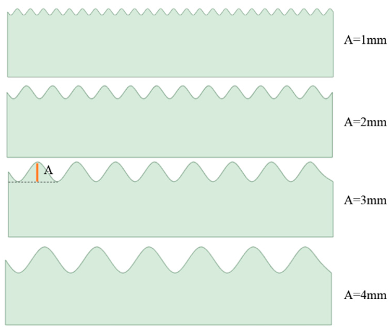
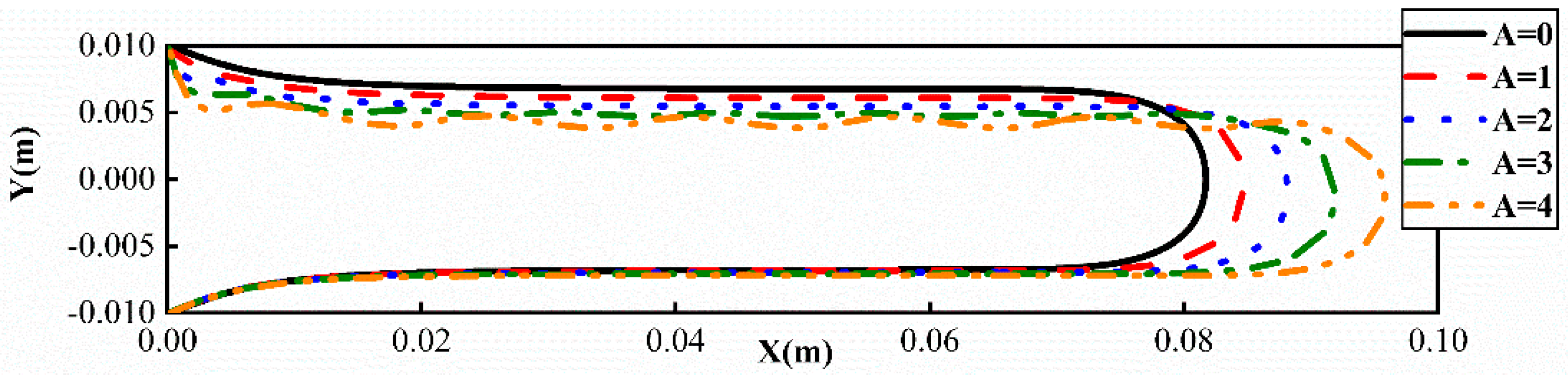
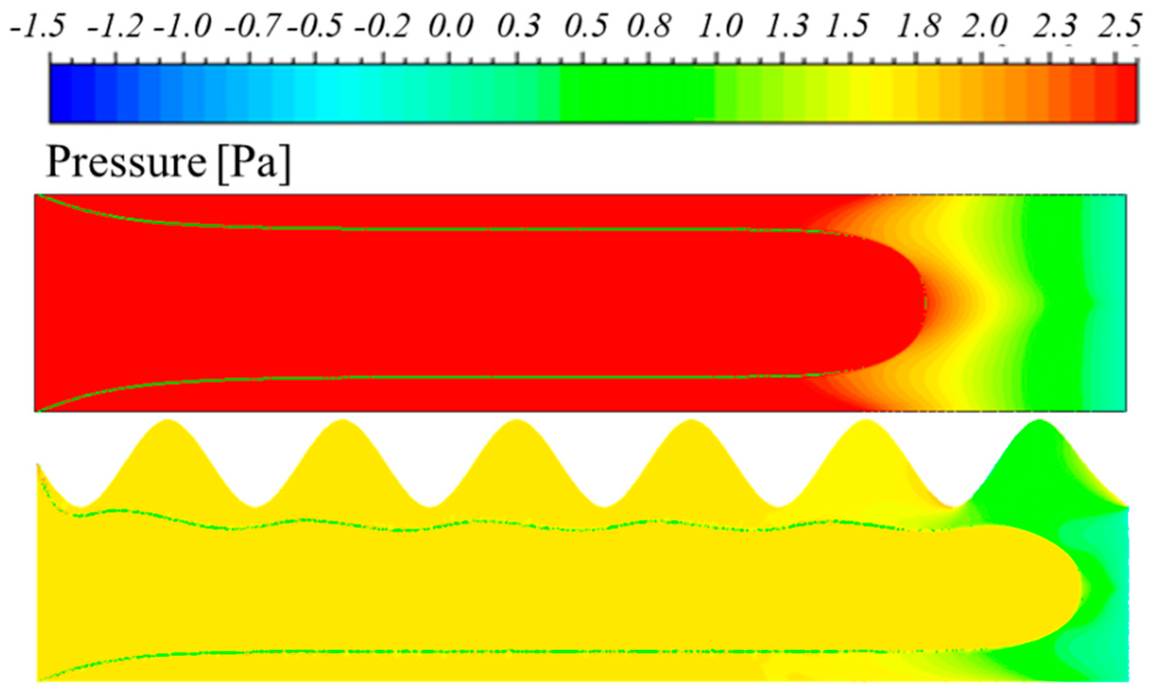
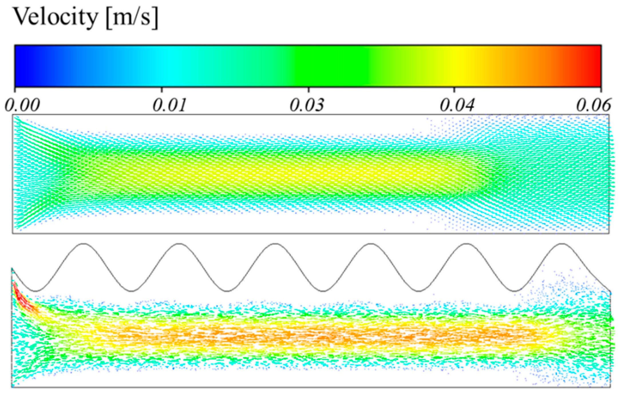
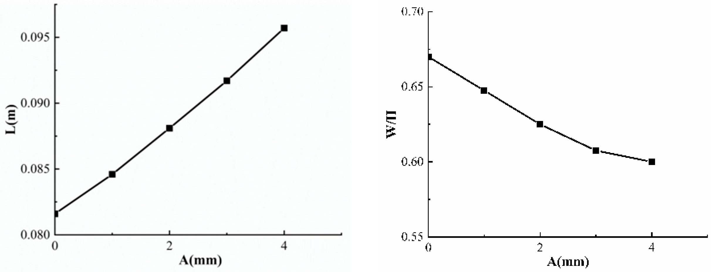
6. Effect of Different Amplitudes on Viscous Fingering

The upper plate’s form was altered to a sine function with different amplitudes (A), as shown in Figure 12. As the amplitude grows, the length of the viscous fingering increases and the relative breadth decreases, as shown by the comparison of the morphology of viscous fingering under different amplitudes in Figure 13. Additionally, the upper edge of the viscous finger will become unstable and experience substantial variations when the amplitude reaches 3 mm. As the amplitude grows further, up to A = 4 mm, the frequency and amplitude of the fluctuation grow as well, as seen in Figure 14. With a straight top plate and an amplitude of A = 4 mm, we examined the pressure and velocity of the viscous fingering phenomenon. It is evident from Figure 15 that when the top plate has an amplitude, as opposed to when it is a straight line, the pressure of the viscous finger entering the interior is lower. This is because the upper plate at is concave the entrance, which compresses the air there and increases speed, with a maximum speed of 0.09 m/s, as illustrated in Figure 16. Since its internal pressure is lowered, the distance travelled by the viscous fingertip at high speed is greater than the distance travelled by the top plate in a straight line.
We examined viscous fingering length and width under various amplitude circumstances, as shown in Figure 17. A linear connection between amplitude and length may be noticed in the left graph, where the viscous finger moves farther the bigger the amplitude. Formula (9), which represents the linear connection between the viscous fingering length and amplitude may be obtained by fitting the data. The right graph also demonstrates how the relative width reduces as the amplitude increases. Similarly, by fitting the data, we can obtain Formula (10). It is clear from the formula that there is a power-exponential connection between the relative width and amplitude. Formulas (9) and (10) may be used to quickly calculate displacement efficiency in engineering applications by predicting the relative breadth and length of viscous fingering under various amplitudes on the top plate.
L = 0.081 + 0.0035 A
W / H = 0.112 e ^ ( ( A ) 3.84 ) + 0.56

7. Conclusions

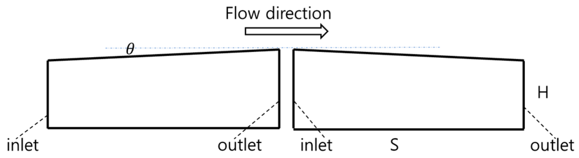
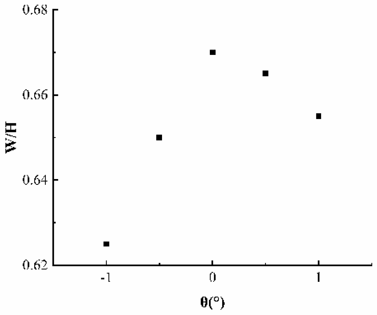
  • When air is used to replace shear-thinning fluids in a classical HSC, a continuous tiny depth gradient is introduced, and this causes the viscous fingering length to be directly linked to the depth gradient. The gradient shifts from a negative to a positive value, which causes a progressive decrease in viscous fingering length. When there is a depth gradient, viscous fingering’s relative breadth shrinks but at θ = 0 ° , its relative breadth is at its greatest. Additionally, a positive depth gradient results in a wider relative breadth than a negative depth gradient. The smallest relative width is observed when the depth gradient is θ = −1°.
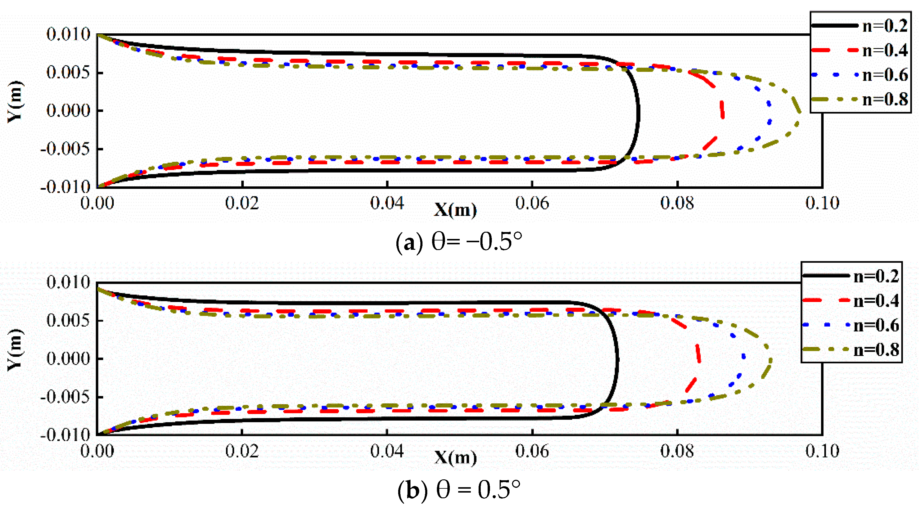
  • The width of viscous fingering narrows and the distance travelled lengthens as the value of n rises, regardless of whether the depth gradient is positive or negative. This is due to the fact that when n decreases, the viscosity non-uniformity increases, and as the viscosity ratio rises, resistance also rises. The front end of the two-phase contact line moves more slowly as a result, and the flow distance is reduced. These qualities may be used in petroleum engineering to create high-quality and effective oil displacement through the introduction of innovative power-law fluids.
  • It has been found that altering the form and amplitude of the top plate has no effect on viscous fingering when the control amplitude is maintained constant. Additionally, for various amplitudes (A), there is a linear connection between amplitude and length. This implies that the viscous finger moves farther as the amplitude rises. On the hand, a power-exponential function may be seen in the connection between the relative width and amplitude, where the relative width shrinks as the amplitude increases. Engineers may easily calculate the displacement efficiency in engineering applications by using these concepts to forecast the relative width and length of viscous fingering under various top plate amplitudes and geometries.

Author Contributions

Conceptualization, Z.Q. and M.M.; methodology, Y.W.; software, M.M.; validation, Z.Q., M.M. and Y.W.; formal analysis, C.M.; investigation, Z.Q.; resources, M.M.; data curation, Z.Q. and M.M.; writing—original draft preparation, Z.Q. and M.M.; writing—review and editing, Y.W.; visualization, S.-K.L.; supervision, Y.W.; project administration, S.-K.L.; funding acquisition, Z.Q., S.-K.L. and C.M. All authors have read and agreed to the published version of the manuscript.

Funding

This work was supported by the Natural Science Foundation of Shandong Province under Grant ZR2022QE085 and ZR2022MA069, the Regional Leading Research Center of NRF and MOCIE (NRF-2019R1A5A8083201) and the Basic Science Research Program through the NRF of Korea funded by the MEST (NRF-2023R1A2C1003691).

Institutional Review Board Statement

Not applicable.

Informed Consent Statement

Not applicable.

Data Availability Statement

Not applicable.

Conflicts of Interest

The authors declare no conflict of interest.

References

  1. Hosmy, G.M. Viscous Fingering in Porous Media. Annu. Rev. Fluid Mech. 1987, 19, 271–311. [Google Scholar]
  2. Wooding, R.A.; Morel-Seytoux, H.J. Multiphase Fluid Flow Through Porous Media. Annu. Rev. Fluid Mech. 1976, 8, 233–274. [Google Scholar] [CrossRef]
  3. Bensimon, D.; Kadanoff, L.P.; Liang, S.; Shraiman, B.I.; Tang, C. Viscous flows in two dimensions. Rev. Mod. Phys. 1986, 58, 977. [Google Scholar] [CrossRef]
  4. Chen, X.L.; Li, Y.Q.; Liao, G.Z.; Zhang, C.M.; Xu, S.Z.; Qi, H.; Tang, X. Experimental investigation on stable displacement mechanism and oil recovery enhancement of oxygen-reduced air assisted and oil recovery enhancement of oxygen-reduced air assisted gravity drainage. Pet. Explor. Dev. 2020, 47, 836–845. [Google Scholar] [CrossRef]
  5. Tsai, M.C.; Wei, S.Y.; Fang, L.; Chen, Y.C. Viscous fingering as a rapid 3D pattering Technique for Engineering cell-Laden Vascular-Like Constructs. Adv. Healthc. Mater. 2022, 11, 2101392. [Google Scholar] [CrossRef] [PubMed]
  6. Grotberg, J.B.; Jensen, O.E. Biofluid Mechanics in Flexible Tubes. Annu. Rev. Fluids Mech. 2004, 36, 121–147. [Google Scholar] [CrossRef]
  7. Huh, D.; Fujioka, H.; Tung, Y.C.; Futai, N.; Paine, R.; Grotberg, J.B.; Takayma, S. Acoustically detectable cellular-level lung injury induced by fluid mechanical stresses in microfluidic airway systems. Proc. Natl. Acad. Sci. USA 2007, 104, 18886–18891. [Google Scholar] [CrossRef]
  8. Nadirah, L.; Abdurahman, H.N.; Rizauddin, D. Rheological study of Petroleum fluid and oil-in water emulsion. Int. J. Eng. Sci. Res. Technol. 2014, 3, 2277–9655. [Google Scholar]
  9. Gorell, S.B.; Homsy, G.M. A theory of the optimal policy of oil recovery by secondary displacement processes. SlAM J. Appl. Math. 1983, 43, 79–98. [Google Scholar] [CrossRef]
  10. Orr, F.M., Jr.; Taber, J.J. Use of carbon dioxide in enhanced oil recovery. Science 1984, 224, 563–569. [Google Scholar] [CrossRef] [PubMed]
  11. Saffman, P.G.; Taylor, G.I. The Penetration of a fluid into a porous medium or Hele-Shaw cell containing a more viscous liquid. Proceeding of the Royal Society of London. Ser. A Math. Phys. Sci. 1958, 245, 312–329. [Google Scholar]
  12. Chuoke, R.L.; Van der Meurs, P.; Van der pole, C. The instability of slow, immiscible, viscous liquid-liquid displacement in permeable media. Trans. AIME 1959, 216, 188–194. [Google Scholar] [CrossRef]
  13. He, A.; Belmonte, A. Inertial effects on viscous fingering in the complex plane. J. Fluid Mech. 2011, 668, 436–445. [Google Scholar] [CrossRef]
  14. Al-Housseiny, T.T.; Tsai, P.A.; Stone, H.A. Control of interracial instabilities using flow geometry. Nat. Phys. 2012, 8, 747–750. [Google Scholar] [CrossRef]
  15. Eriksen, F.K.; Moura, M.; Jankov, M.; Turquet, A.L. Transition from viscous fingers to compact displacement during unstable drainage in porous media. Phys. Rev. Fluids 2022, 7, 013901. [Google Scholar] [CrossRef]
  16. Singh, A.; Pandey, K.M.; Singh, Y. CFD analysis of viscous fingering in Hele-Shaw cell for air-glycerine system. Mater. Today Proc. 2021, 45, 6381–6385. [Google Scholar] [CrossRef]
  17. Redapangu, P.R.; Vanka, S.P.; Sahu, K.C. Multiphase lattice Bolt zmann simulations of buoyancy-induced flow of two immiscible fluids with different viscosities. Eur. J. Mech. 2012, 34, 105–114. [Google Scholar] [CrossRef]
  18. Bakharev, F.; Campoli, L.; Enin, A.; Matveenko, S.; Petrova, Y.; Tikhomirov, S.; Yakovlev, A. Numerical investigation of viscous fingering phenomenon for raw field data. Transp. Porous Media 2020, 132, 443–464. [Google Scholar] [CrossRef]
  19. Guo, Y.A.; Cai, S.; Li, D. Effect and mechanism analysis of porous media heterogeneity on water-oil immiscible displacement. Sci. China Technol. Sci. 2022, 52, 807–818. [Google Scholar]
  20. Jha, B.; Cueto-Felgueroso, L.; Juanes, R. Fluid mixing from viscous fingering. Phys. Rev. Lett. 2011, 106, 194502. [Google Scholar] [CrossRef]
  21. Logvinov, O.A. Viscous fingering in poorly miscible power-law fluids. Phys. Fluids 2022, 34, 063105. [Google Scholar] [CrossRef]
  22. Qin, Z.; Wu, Y.T.; Ma, C.; Lyu, S.K. Effect of power law on viscous fingering behaviour of shear-thinning fluid in a lifted hele-shaw cell. J. Mech. Sci. Technol. 2023, 37, 3555–3562. [Google Scholar]
  23. Leung, L.T.Y.; Kowal, K.N. Lubricated viscous gravity currents of power-law fluids. Part 1. Self-similar flow regimes. J. Fluids Mech. 2022, 940, A26. [Google Scholar] [CrossRef]
  24. Lindner, A.; Bonn, D.; Poire, E.C.; Amar, M.B.; Meunier, J. Viscous fingering in non-newtonian fluids. J. Fluids Mech. 2002, 469, 237–256. [Google Scholar] [CrossRef]
  25. Pouplard, A.; Tsai, P.A. Viscous Fingering Instability of Complex Fluids in a Tapered Geometry. arXiv 2022, arXiv:2205.08019. [Google Scholar]
  26. Gallaway, J.W.; Desai, D.; Gaikwad, A.; Corredor, C.; Banerjee, S.; Steingart, D. A lateral microfluidic cell for imaging electro deposited zinc near the shorting condition. J. Electrochem. Soc. 2010, 157, A1279. [Google Scholar] [CrossRef]
  27. Taylor, G.I. Cavitation of a viscous fluid in narrow passages. J. Fluids Mech. 1963, 16, 595–619. [Google Scholar] [CrossRef]
  28. Shi, Y.; Tang, G.H. Simulation of Newtonian and non-Newtonian rheology behavior of viscous fingering in channels by the lattice Boltzmann method. Comput. Math. Appl. 2014, 68, 1279–1291. [Google Scholar] [CrossRef]
Figure 1. The free-falling paint phenomenon of viscous fingering.
Coatings 13 01848 g001
Figure 2. Introducing depth gradient in an HSC: positive gradient (left) and negative gradient (right).
Coatings 13 01848 g002
Figure 3. Shape of the upper plate (square, wavy, triangular).
Coatings 13 01848 g003
Figure 4. Meshed computational domain.
Coatings 13 01848 g004
Figure 5. Position of viscous fingering at different depth gradients at n = 0.4 at 3 s.
Coatings 13 01848 g005
Figure 6. The distribution of molecular viscosity at θ = 0 ° , (a) the molecular viscosity range is the default, (b) the molecular viscosity ranges from 1.79 ×   10 5   kg / m · s to 0.5 kg / m · s .
Coatings 13 01848 g006
Figure 7. The length of viscous fingering at different depth gradients at n = 0.4 at 3 s.
Coatings 13 01848 g007
Figure 8. Relative width of viscous fingering at different depth gradients at n = 0.4 at 3 s.
Coatings 13 01848 g008
Figure 9. Positions of viscous fingering for different n at 2.9 s.
Coatings 13 01848 g009
Figure 10. Development of viscous fingering under different shapes of n = 0.4.
Coatings 13 01848 g010
Figure 11. Internal pressure contour of different upper plates in the HSC.
Coatings 13 01848 g011
Figure 12. Different amplitudes on the upper plate with a sine function.
Coatings 13 01848 g012
Figure 13. Viscous fingering at different amplitudes at 2.8 s.
Coatings 13 01848 g013
Figure 14. Viscous fingering with amplitude A = 4 cm at 2.8 s.
Coatings 13 01848 g014
Figure 15. Pressure contour with a straight line on the upper plate (up) and an amplitude of 4 cm (down).
Coatings 13 01848 g015
Figure 16. Velocity vector contour with a straight line on the upper plate (up) and an amplitude of 4 cm (down).
Coatings 13 01848 g016
Figure 17. Viscous finger length (left) and relative width (right) under different amplitudes.
Coatings 13 01848 g017
Table 1. Ca at different angles.
θ θ = 1 ° θ = 0.5 ° θ = 0 ° θ = 0.5 ° θ = 1 °
Ca 1.08 × 10 3 1.11 × 10 3 1.14 × 10 3 1.19 × 10 3 1.25 × 10 3
Disclaimer/Publisher’s Note: The statements, opinions and data contained in all publications are solely those of the individual author(s) and contributor(s) and not of MDPI and/or the editor(s). MDPI and/or the editor(s) disclaim responsibility for any injury to people or property resulting from any ideas, methods, instructions or products referred to in the content.

