Article

Tribological and Grinding Properties of Spherical Diamond Grown on a Rough Discontinuous Surface

1
State Key Laboratory of Power Grid Environmental Protection, Wuhan 430074, China
2
School Energy and Mechanical Engineering, Shanghai University of Electric Power, Shanghai 200090, China
3
Shanghai Key Laboratory of Materials Protection and Advanced Materials in Electric Power, Shanghai 200090, China
4
Shanghai Non-Carbon Energy Conversion and Utilization Institute, Shanghai 200240, China
*
Author to whom correspondence should be addressed.
Coatings 2023, 13(10), 1735; https://doi.org/10.3390/coatings13101735
Submission received: 13 September 2023 / Revised: 28 September 2023 / Accepted: 3 October 2023 / Published: 5 October 2023
(This article belongs to the Special Issue Trends in Coatings and Surface Technology)

Abstract

:
Spherical diamond particles have great potential as additive materials for improving lubricity of lubricants, and yet the complicated preparation process is difficult to meet the current industrial demand. Therefore, a novel method was proposed to deposit mass spherical diamond on the discontinuous silicon nitride (Si3N4) powder substrate by the hot filament chemical vapor deposition method. The results revealed that the substrate was covered by the spherical diamond grains with a diameter of about 20 μm. Thereafter, they were used as lubricant additives to examine the tribological and grinding properties. Therein, the Si3N4 surface had a remarkable reduction in surface roughness by a factor of 124.62% as compared to that without spherical diamond powder, while GCr15 alloy had a 31.17% increase under the same condition. Hence, our method provides a promising way to deposit the mass spherical diamond powder that might become a great abrasive material for machining the ceramic.

1. Introduction

In industrial production and processing, the friction between various components was inevitable and always existed in mechanical motion. However, the friction process not only wasted much mechanical energy, but also led to wear and malfunction of components. Therefore, it was necessary to take measures to reduce the surface friction between mechanical devices and prolong their application life. The lubricant has been proven to be one of the most effective and widely used means to reduce friction and wear [1]. In practice, it was usually necessary to use additives to improve the lubricating properties of the lubricant, so as to meet different industrial requirements. However, the traditional additives were mostly based on simply improving the chemical properties of the lubricant, and there were also environmental pollution problems, which were difficult to adapt to the developing requirements of modern industrialization. It has been found that the addition of micro-nanoparticles to lubricants can improve lubricity, low-temperature fluidity and anti-wear properties [2,3]. Moreover, the inclusion of micro-nanoparticles allowed the friction state between the friction partners to be altered, which greatly improved the lubrication effect. Hence, for solid additives, spherical shape was undoubtedly a more desirable three-dimensional (3D) surface structure, which could convert sliding friction into rolling friction and drastically reduce surface wear [4].
Diamond prepared by chemical vapor deposition (CVD) had gained extensive attention due to its excellent properties, such as low friction coefficient, super hardness, well wear resistance and high-thermal conductivity [5,6]. Currently, small spherical materials have been widely applied in many industrial fields, such as semiconductors, tribology and advanced catalysts [7,8,9]. Generally, the CVD diamond had a columnar shape with {111} crystalline face after a deposition time of several hours, while the spherical diamond grains commonly appeared at the initial stage of CVD deposition and only discretely distributed on the substrate surface at nanometric scale size [10]. Hence, it was significant to research the deposition process of large spherical diamond for the tribological applications of CVD diamond [11,12].
It was found that the growth of the spherical diamond grains was highly correlated with the pressure and temperature during the CVD deposition [13]. The spherical diamond grains with an average diameter of 7 μm had been grown under the pressure of 1 kPa [9], which was much lower than the columnar shaped diamond grains (3–5 kPa) [14,15]. Meanwhile, it was difficult to ensure the uniform distribution of grains at such low pressure [16]. In consideration of the fact that such spherical diamond grains were obtained by deposition at low temperature or low pressure, this may be attributed to the incomplete growth of lamellar diamonds [17]. On the other hand, an intermediate layer deposited in the front of the substrate surface had shown good feasibility to fabricate the spherical diamonds grains [18]. Discontinuous spherical grains might appear on the rough areas of the aluminum or nickel interlayer [19,20]. Therefore, a rough surface was also potentially favorable for the growth of spherical diamond grains. In addition, nanocrystalline spherical diamond grains with a 3–5 nm diameter had been obtained by the commercial B-3 bombardment nano-diamond technology [21], but the complex deposition process and small diameter hardly satisfied the mass production at the current stage.
In this work, a novel diamond deposition method was proposed to explore the growth of the spherical diamond grains. The method was primarily aimed at creating environmental conditions adapted to the growth of spherical diamonds by increasing the surface roughness of the deposited substrate for which silicon nitride (Si3N4) powder was directly employed as substrate. Thereafter, scanning electron microscopy (SEM), a transmission electron microscope (TEM), Raman spectroscopy (RM), X-ray diffraction (XRD), X-ray photoelectron spectroscopy (XPS) and a Fourier transform infrared spectrometer (FTIR) were performed to characterize the deposited diamond grains. Finally, the tribological and grinding properties of the spherical diamond grains were also evaluated.

2. Experimental

In order to achieve a high roughness surface for fabricating the spherical diamond coating, the 99.99% pure Si3N4 powder with about 20 nm diameter was selected as the substrate in this work. An important step in this subsequent work was to compact and shape the Si3N4 powder to prevent tiny particles from being pumped out of the CVD chamber in a vacuum environment. Here, the clean Si3N4 powder was put into a mold and subsequently extruded with an external load of 1000 N to form a circular sheet substrate with Ø40 × 0.4 mm2. In addition, the commercial reaction-sintered flat Si3N4 insert with square geometry of 10 × 10 × 3 mm3 was also employed as the substrate to deposit the diamond grains with aims of a comparison. Prior to the deposition experiments, pretreatments need to be performed for the sintered Si3N4 substrate by the following three steps: (i) roughening the surface using diamond powder slurry with abrasive paper for 20 min; (ii) cleaning with deionized water in an ultrasonic vessel for 10 min; and (iii) washing with a high-purity acetone solution in an ultrasonic vessel for 20 min.
The diamond grains were fabricated with the conventional hot filament CVD technology in a bias-enhanced reactor. The high temperature was offered by the hot filaments using four pair-twisted tantalum wires that were separated in a parallel and equidistance manner with a ~20 mm interval. The distance between the hot filaments and substrate was set at ~10 mm. The temperature of filament during deposition was 2000–2200 °C to keep the surface temperature at approximately 800–900 °C. A mixture of CH4 and H2 was used as the reaction gas to deposit the diamond coatings, and the concentrations were set to 10 and 240 sccm, respectively. The deposition process was divided into the nucleation stage and the growth stage, and the relevant parameters are listed in Table 1. During the 1h nucleation stage, the pressure in the CVD reaction chamber was set at 1.5–2.0 kPa to increase the nucleation density [22]. Thereafter, the reaction pressure was adjusted to 4.5–5.0 kPa and the time was set to 6h to provide a suitable condition to deposit the diamond grains in the growth phase.
The surface and cross-sectional morphologies of diamond coatings were characterized by SEM (Hitachi Ltd., Tokyo, Japan) at 5 kV, which can explore the effect of the substrates on the morphologies of the as-deposited diamond grains. The RM (Horiba Jobin Yvon Ltd., Paris, France) using an Ar+ laser with an excitation wavelength of 532 nm was performed to analyze the diamond quality on both substrates. The XRD (Bruker Ltd., Ettlingen, Germany) and XPS (Thermo Fisher Ltd., Waltham, MA, USA) were employed to evaluate the lattice properties and the chemical bonding of diamond grains, respectively. Furthermore, the TEM (JEOL Ltd., Tokyo, Japan) was adopted to analyze the atomic structure of the spherical diamond grains at 200 kV, and the FTIR (Thermo Fisher Ltd., Waltham, MA, USA) was performed to determine the chemical composition. Thereafter, the spherical diamond grains were broken into particles to explore their tribological and grinding applications, and the abrasive surfaces were observed by a white light interferometer.

3. Results and Discussion

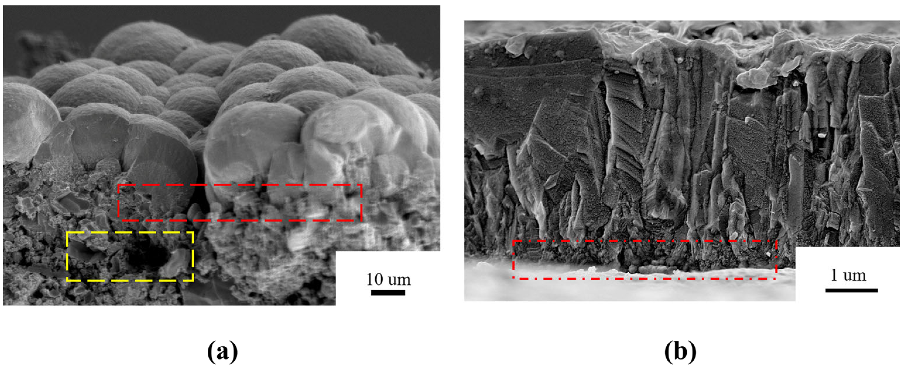
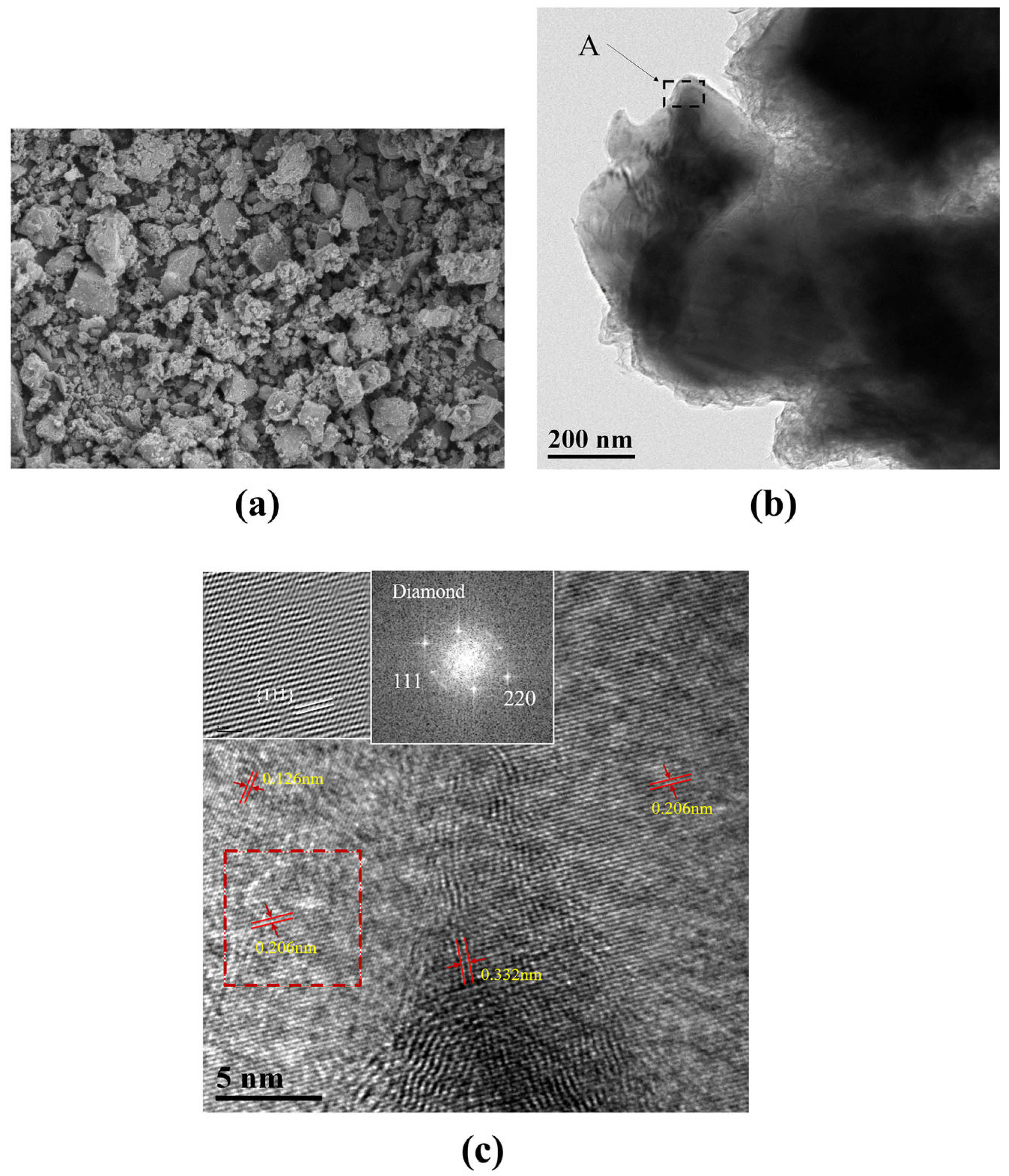
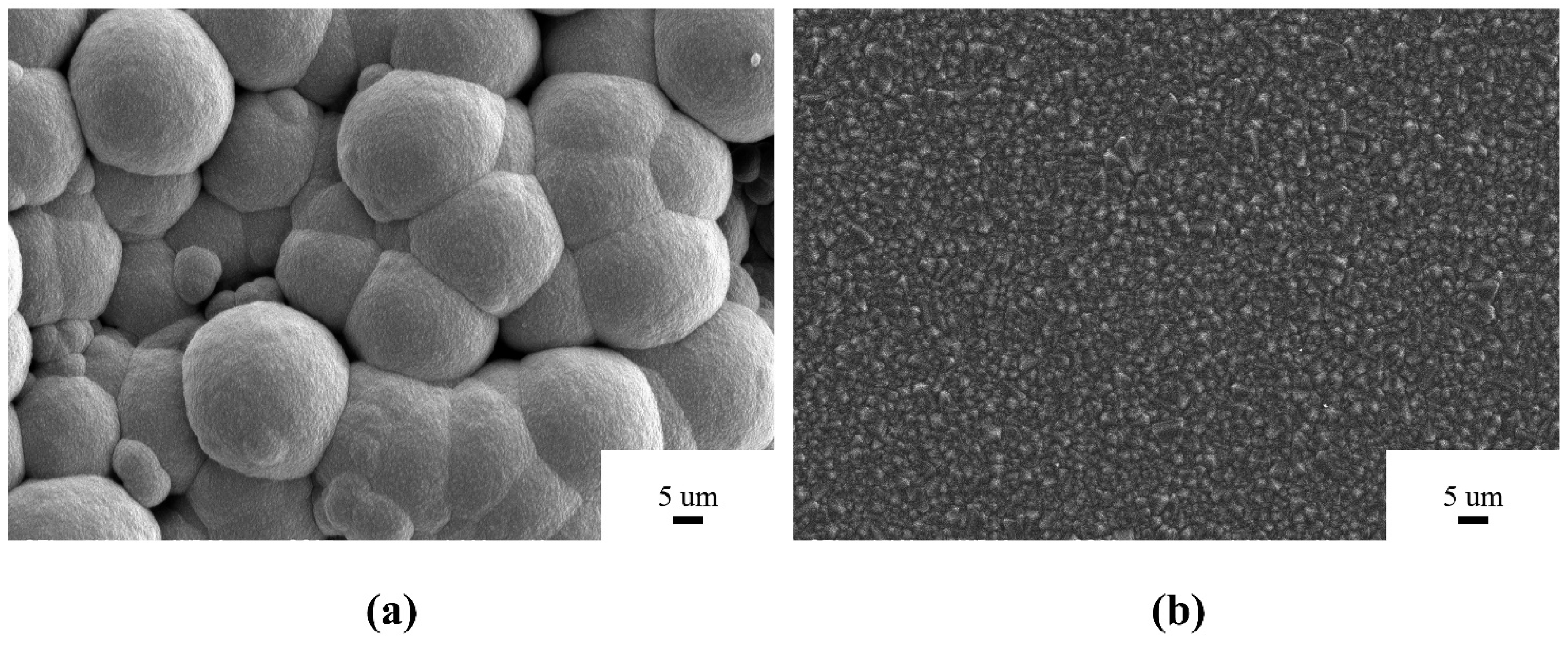
3.1. Characteristics of the As-Deposited Diamond Grains

For the purpose of the following description, the diamond grains prepared on the powder are referred to as P-diamond, and the diamond grains prepared on the sintered Si3N4 insert are labeled as S-diamond, and their SEM images are shown in Figure 1. It can be seen that the Si3N4 powder substrate was covered by the spherical diamond grains with a diameter of 15–20 µm, which was larger than those reported in the previous literature [23]. To the best of our knowledge, such a P-diamond ball might be the largest in the current deposition process, which might mainly result from the special physical properties of the discontinuous powder substrate. For the sintered Si3N4 substrate, the S-diamond coating was well deposited with a normal flat {111} crystal plan, which showed the similar surface morphology of the classical microcrystalline diamond (MCD) coating [24]. As compared with the P-diamond coating, the S-diamond coating exhibited a dense surface without any hole. Hence, although the common consensus was reached on the fact that the surface roughness significantly affects the surface morphology of CVD diamond coating, the discontinuous surface substrate still induced a very interesting and special behavior of motiving the fabrication of the large spherical diamond grains that was never observed before.
In order to further explore the growth mechanism of spherical diamond grains, the cross-sectional morphologies of two diamond coatings were observed, as shown in Figure 2. Here, the preparation for the cross-section samples was performed by the different broken method. Two clean tweezers were employed to hold the corresponding edges of P-diamond coating, and then the gentle force was imposed to break the powder substrate. Since the sintered Si3N4 substrate is a brittle and insulating material, we adopted the mechanical method to directly split the S-diamond coating, rather than wire cutting technology. In Figure 2a, the spherical morphology led to a large fluctuating interaction in the vertical direction, which resulted in the high surface roughness of the as-deposited P-diamond coating. Meanwhile, an impressive thickness of about 20 μm suggested the high growth rate of the P-diamond coating relative to that of the normal CVD diamond coating. For the S-diamond coating, the cross-sectional morphology clearly showed a columnar growth manner. The relatively high smooth surface led to a flat diamond surface with only 5 µm thickness, which was much lower than that of the P-diamond coating. In addition, apparent large-sized pores were observed at the junction of the P-diamond film and the Si3N4 powder substrate (see red dashed rectangular box), which did not occur significantly in S-diamond, probably due to the uneven surface morphology of the powder substrate, resulting in the failure of the spherical diamond to spread over the entire surface even at the nucleation stage. In fact, although the powder substrate was compressed by external loads prior to the experiment, holes of various sizes still existed internally (see yellow dashed rectangular box), which allowed the spherical diamond to be susceptible to cohesion, and thus, clustering together due to the relative looseness of the substrate surface during the deposition process.

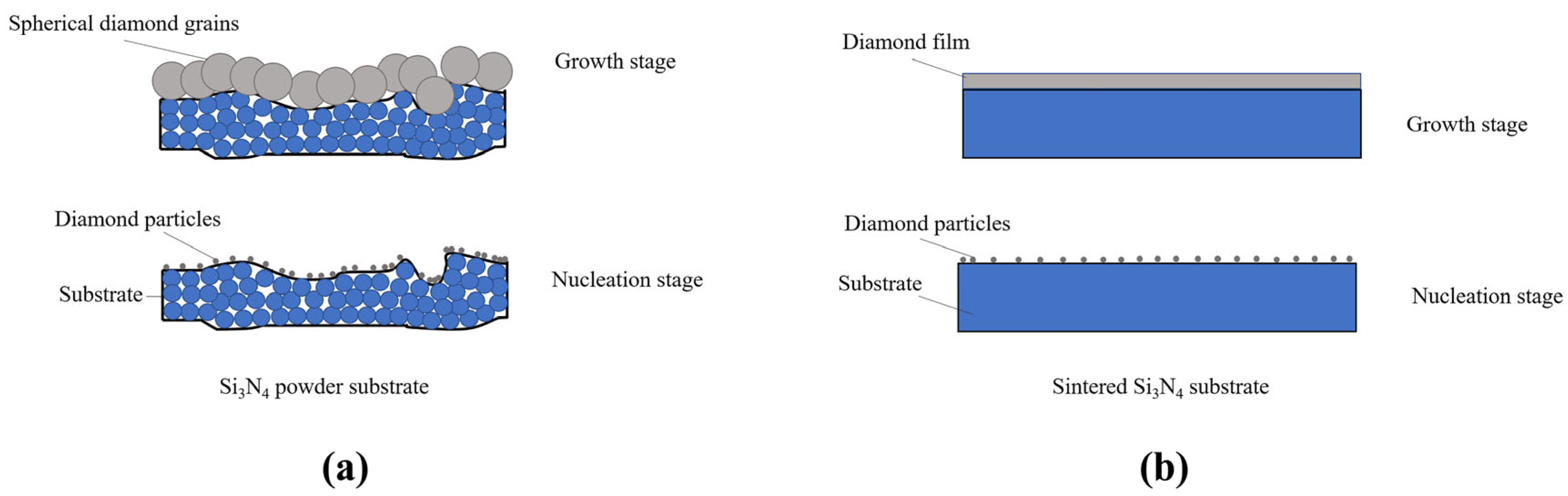
3.2. Deposition Mechanism of the As-Deposited Diamond Grains

In this work, we were devoted to the deep investigation on the mechanism of the considerable discrepancy in surface morphologies between P-diamond coating and S-diamond coating. It was noted that the main difference between these two diamond coatings was the case of whether the substrate was a discontinuous surface or not. Here, a hypothesis was proposed to describe the growth process of P-diamond coating. Meanwhile, the S-diamond coating was also considered for comparison. Figure 3 shows the proposed schematic procedure of diamond growth. Although the Si3N4 powder substrate was mechanically pressed under a larger load, and thus flattened the substrate surface prior to deposition, it was still an uneven surface at the microscopic scale. Many large holes were distributed on the surface of powder substrate as compared to the sintered substrate. The coupling between inhomogeneous materials and discontinuous surface might cause difficulties in the epitaxial growth of diamond grains in the horizontal direction. In addition, during the deposition process, the carbon atom reactive groups gathered more easily in the recesses of the substrate surface before the nucleation stage, which led to the difficulty of diamond nanoscale nucleation sites to spread uniformly over the whole surface, and thus aggregated mutually to grow into larger spheres. In contrast, the sintered Si3N4 insert can present a smooth and flat surface by polishing, as shown in Figure 3b. The flat surface enabled the diamond crystal nucleus to form larger crystals by diffusion and migration after stabilization in the nucleation stage, which in turn generated a continuous surface uniformly over the entire substrate.

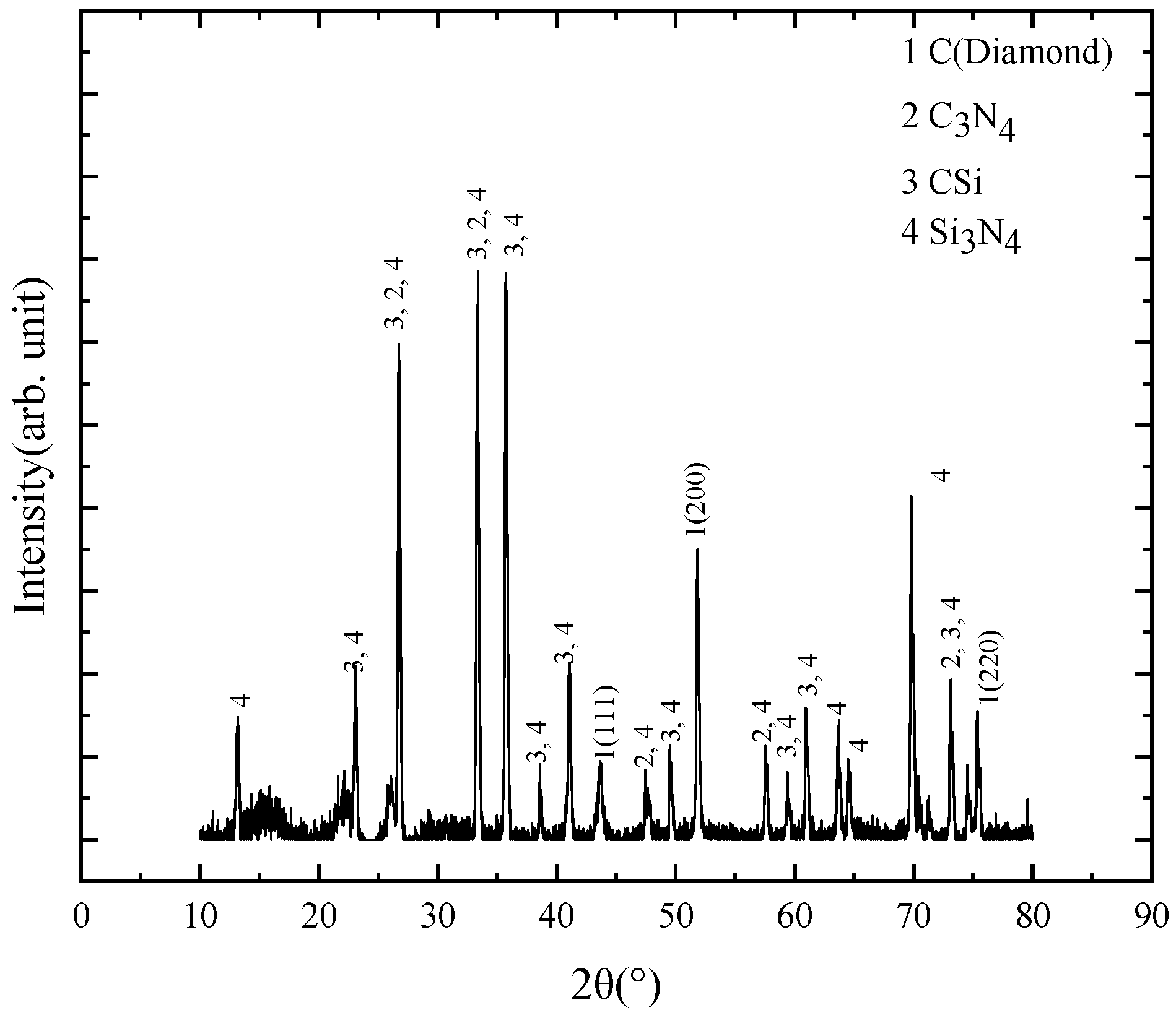
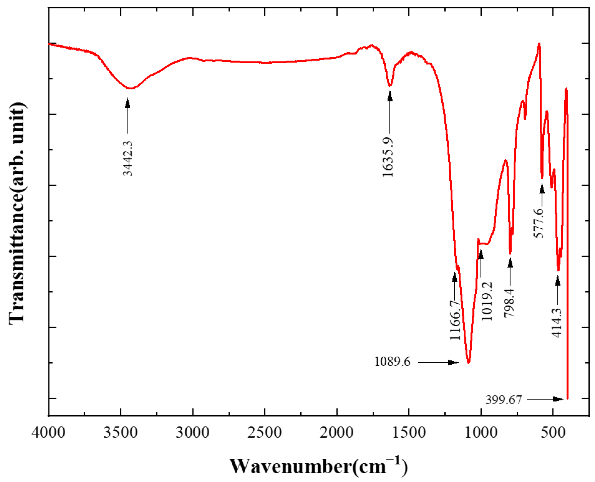
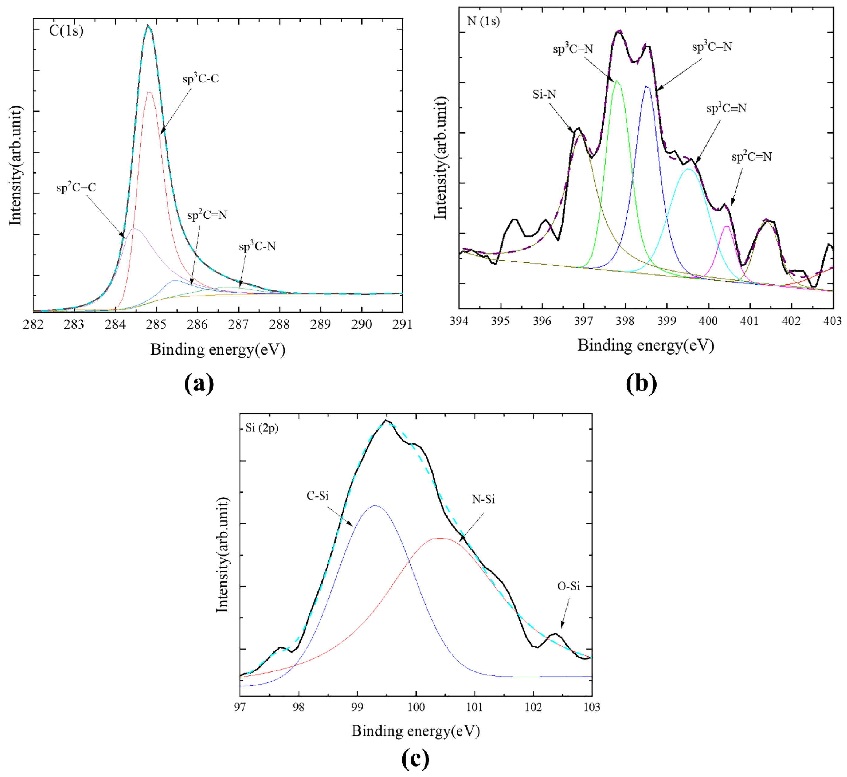
3.3. Chemical Bonds of the As-Deposited Diamond Grains

The Raman spectrum of the P-diamond and S-diamond were plotted separately in Figure 4 to evaluate the structural composition and quality of the materials. A natural diamond Raman line, located at 1332.33 cm−1, was found in the Raman curve of the P-diamond [15], and the main stem of the spectrum was relatively flat, which indicated the good quality of diamond particles. Meanwhile, the peak width at 1332.33 cm−1 might be caused by the tiny size of the diamond grains [25], and a similar Raman pattern was obtained in a previous study of spherical grains [9]. In addition, a high G-peak at 1582.71 cm−1 indicated a small amount of sp2 state carbon existed in the diamond grains, which was generally associated with the amorphous carbon layer [26]. In contrast, a sharp and narrow Raman peak at 1336.7 cm−1 of the S-diamond Raman curve with a slight offset compared to the typical diamond was observed, which suggested the existence of diamond misalignment in the film. This might result from the diamond crystal deformation due to the mismatch of crystal parameters and thermal expansion coefficient between diamond and substrate. Meanwhile, the high G-peak at 1572.2 cm−1 might be a Raman scattering caused by the sp2 carbon bond, confirming a high degree of misalignment with respect to the diamond Raman peak. It was noted that characteristic peaks of varying intensity were also present in the 1650~1700 cm−1 region, which could be attributed to the sp2 hybridized carbon [27] and the C=O group [28]. However, the object of detection was inorganic and there were no oxygenated compounds involved in the deposition reaction, thus it could be determined that the Raman peaks were not caused by C=O groups.
A typical XRD pattern of P-diamond grains in the 2θ range from 20° to 80° is shown in Figure 5. The shape factor (K) was set as 0.94 and the X-Ray wavelength (λ) was 1.5406 Å. The pattern consists primarily of four phases: diamond, C-Si, C-N, and Si-N. The peaks at 2θ = 43.915°, 51.283° and 75.372° corresponded to the {111}, {200} and {220} diamond crystal plane, respectively (PDF#43-1104). The {200} crystal plane had a stronger energy peak than the {111} and {220} ones, and thus a considerable portion of the spherical diamond grains might grow along the {200} direction. According to the previous studies, the appearance of other peaks can be attributed to the formation of C-Si, C-N, and N-Si bonds during diamond grain growth [29]. Therefore, silicon and nitrogen on the Si3N4 surface had a high potential to react with the carbon-based groups during the diamond grain growth, thus affecting the formation of diamond C-C bonds. This analysis also confirmed the observation in the SEM morphology in which the spherical diamond particles failed to develop a dense coating on the entire substrate surface.
The elements in the P-diamond grains were evaluated by XPS and their chemical states were also detected, as shown in Figure 6. Meanwhile, the deconvolution of the high-resolution spectra was also performed based on Shirley background subtraction. The C (1s) spectrum of the diamond grains were decomposed into four parts located at 284.4, 284.8, 285.6, and 287.2 eV, which were associated with sp2 C=C, sp3 C-C, sp2 C-N/C=N, and sp3 C-N, respectively [30]. The sp3 C-C component had a larger peak area rate (62.8%) as compared to the sp2 C=C component (27.4%), indicating that the diamond coating contained many non-diamond bonds [31]. The sp2/sp2 C=N and sp3 C-N peaks formed during the nitridation process are 9.82% of the total area due to the deposition of polycrystalline diamonds on the loose Si3N4 powder substrate in a high-temperature environment, which had affected the bonding structure [32]. In addition, the peak located at ~283.2 eV (associated with Si-C bonding) was not found in the XPS spectrum, which indicated no Si-C bonding existed in the grains. For the N (1s) spectrum, it was decomposed into five parts located at 397.4, 397.9, 398.5, 399.3, and 400.1 eV, as shown in Figure 6b, which were associated with Si-N, sp3 C-N, sp3 C-N, sp1 C≡N, and sp2 C=N, respectively. Meanwhile, the C-N, C=N and C≡N bonds were also found in the N (1s) spectrum, which was consistent with the results in the C (1s) spectrum. For the Si (2p) spectrum, the two peaks located at 100.9 and 102.0 eV were associated with the Si-C and Si-N bonds, respectively. This further demonstrated the existence of Si-N bonds in the diamond coating. However, the Si-C component existed in the Si (2p) spectrum was not found in the C (1s) spectrum, which may result from the small amount of Si-C bonds in the diamond coating [33].
In order to investigate the tribological and grinding properties of the P-diamond, the larger diamond particles were shattered and further observed by SEM, as shown in Figure 7a. The characteristic diameters of most particles in the broken diamonds can be observed to be no more than 10 μm. The TEM image of broken diamond grains is shown in Figure 7b, and the high-resolution image of region A was shown in Figure 7c. The interplanar spacings of the diamond layers was 0.206 nm, which was close to the {111} plane. In addition, wavy streaks with interplanar spacings of 0.332 nm existed in the bottom middle part of Figure 7c, which might be related to the graphite layers produced during the breaking of P-diamonds. Moreover, a few grains displaying 2D lattice stripes can be seen, and the lattice plane index and normal direction can be determined from the lattice stripe distance. The region shown in the dashed box in Figure 7c was enlarged in the inset. The Fast Fourier Transform (FFT) of this region was located in the upper left side, and the {111} and {220} lattice planes can be easily identified, which were in general agreement with the XRD results.
Fourier transform infrared (FTIR) spectroscopy was commonly performed to characterize the bonding structure of atoms and to measure radiation frequencies through the interaction of infrared radiation and matter. This method was applied in this work to detect the chemical bond composition in P-diamonds, as shown in Figure 8. The peak at 3442.3 cm−1 was mainly caused by the combined in-plane stretching vibration of the N-H and C-H groups in diamond [34,35]. The peak at 1635.9 cm−1 had been confirmed as a result of the in-plane bending vibration of the O-H groups in diamond grains [34]. The peaks at 1019.2, 1089.6, and 1166.7 cm−1 were attributed to the tetrahedral vibrations of the O-Si-C bond. Among them, the peaks at 1019.2 and 1166.7 cm−1 were caused by the bending deformation vibration of the O-Si-C bond within the base plane, while the peak at 1089.6 cm−1 was induced by the stretching vibration of the O-Si-C bond perpendicular to the base plane [35]. In addition, the peak at 798.4 cm−1 was related to the out-of-plane deformation of the sp2 hybridized C-H groups, while the peak at 577.6 cm−1 was thought to be due to the rotational lattice vibration of the -OH group [35]. The peaks at 414.3 and 399.67 cm−1 were associated with the out-of-plane bending vibrational deformation of the sp3 hybridized C-C bond.

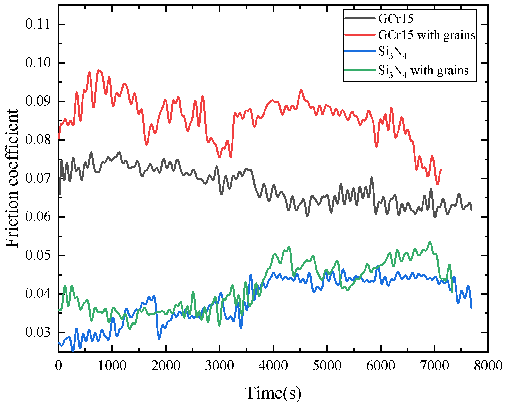
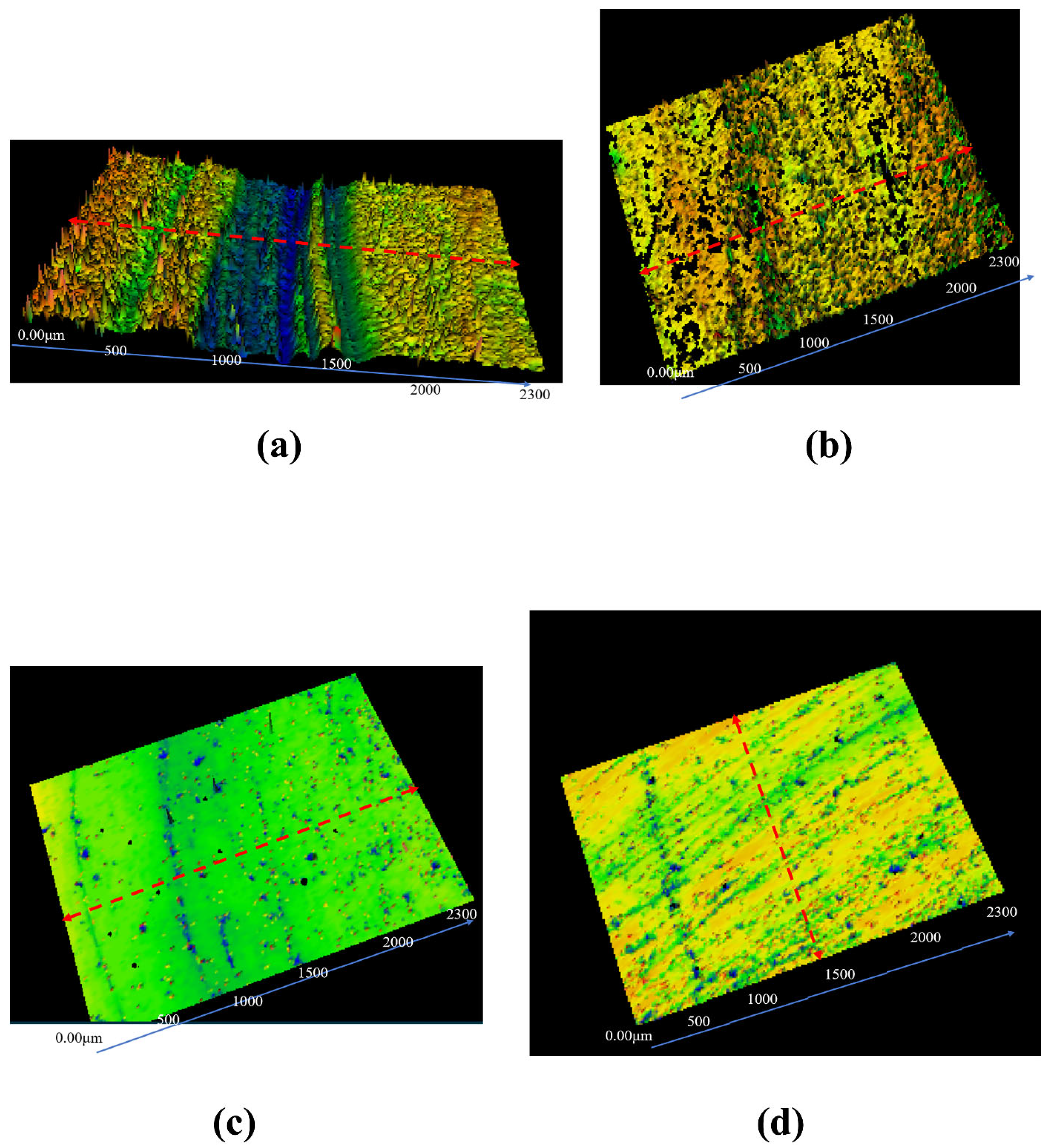
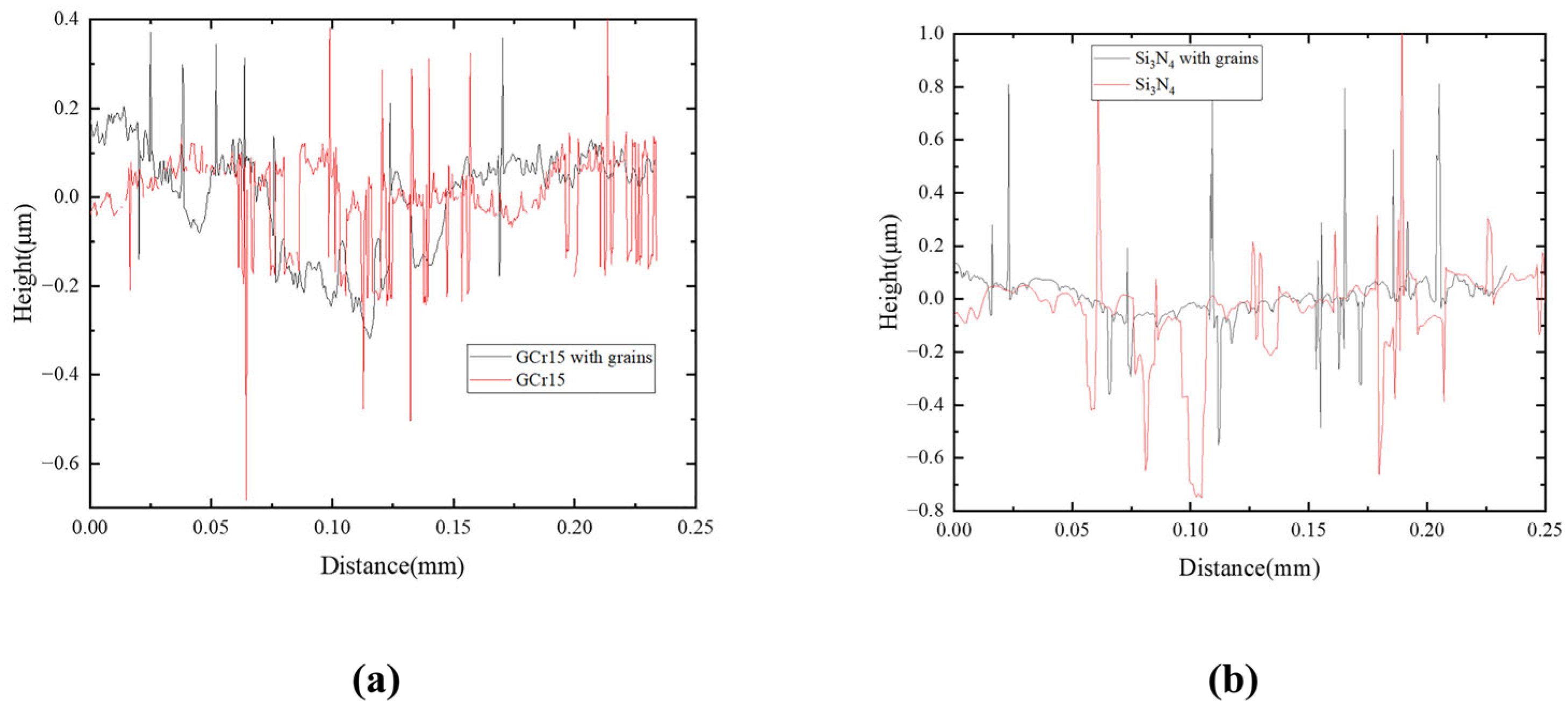
3.4. Tribology and Grinding Properties of As-Deposited Spherical Diamond Grains

A typical tribological wear test was performed to examine the properties of diamond grains with the ball-disk friction machine. The as-deposited diamond grains (1% wt) and oleic acid dispersant (Oleamide, 3% wt) were incorporated into the base lubricant, which used a Poly-alpha-olefin (PAO10) with a viscosity of 67.02 cSt at 40 °C. The oil mixture was ultrasonically stirred at 50 °C for 30 min to ensure the dispersion of the diamond grains in the base lubricant. In the wear tests, the widely available materials GCr15 (HRC58) and Si3N4 (HRC92) were employed as friction pairs. In this case, the samples (surface size of 10 × 10 mm2) and balls (diameter of 4 mm) were used with the same materials and were performed for 2 h of tribological experiments at 600 rpm and 39.18 N (4kg). The diameters of the wear scars after the tests were observed with an optical microscope, and the four sets in friction experiments were named as GCr15, GCr15 with grains, Si3N4, and Si3N4 with grains, as shown in Table 2. In addition, the whole experimental procedure was repeated three times and the data obtained were averaged over the three experiments to ensure the reliability of the results.
Figure 9 shows the friction coefficient curves of the samples in the four sets of experiments. The average values of the friction coefficients of GCr15 with grains, GCr15, Si3N4 with grains, and Si3N4 were 0.0858, 0.0680, 0.0418 and 0.0387, respectively. According to the values obtained, the friction coefficients of all GCr15 materials were greater than those of the Si3N4 materials, indicating that the deposited diamond grains were more suitable for the Si3N4 ceramic materials in terms of friction and wear reduction applications. In addition, all the GCr15 materials showed a trend of decreasing friction coefficients after one hour of testing, and the GCr15 with grains exhibited more reduction. The Si3N4 with grains and Si3N4 exhibited close friction coefficients, with the former increasing by 8% compared to the latter. However, the two groups of experiments in Si3N4 materials still exhibited partially different trends in terms of friction coefficients. The friction coefficient of the Si3N4 set increased by about 0.01 after the friction experiment was conducted for 1 h. Moreover, the friction coefficient of the Si3N4 with grains remained invariant, which indicated that the diamond grains in the oil sample can prevent the friction coefficient from increasing. It was notable that the values of friction coefficients of the four samples were relatively constant after about 4000 s, which was probably due to the protective effect of the oil film gradually formed by the lubricant on the surface after a long period of friction experiment [2,3]. Meanwhile, the mixture of solid additives and liquid lubricants could also form a protective friction layer to reduce friction and wear.
The tribological properties of diamond grains were further evaluated using white light interferometry, and the 3D morphology and 2D profile of the wear grooves of GCr15 and Si3N4 materials after being examined are depicted in Figure 10 and Figure 11, respectively. The deep wear grooves can be clearly observed in the GCr15 with grains set, as seen in Figure 10a, whereas it was not apparent in GCr15 set, as shown in Figure 10b. The Ra of the wear surface of GCr15 with grains was 0.101 μm compared to 0.077 μm for GCr15 in Figure 11a, with an increase of 31.17% for GCr15 with grains set. In addition, the wear surface Ra of the Si3N4 with grains set was 0.065 μm, and the wear surface Ra of the Si3N4 set was 0.146 μm, as shown in Figure 11b. The surface roughness of the Si3N4 with grains set had been reduced by 124.62%, which might be caused by the low hardness of GCr15, resulting in the surface being plowed by diamond grains during the friction process. However, the Si3N4 ceramics were so hard that the diamond grains form a protective layer on the surface and replaces it during the friction process.

4. Conclusions

This work had mainly proposed a novel method for the preparation of spherical diamond grains and emphasized the application of the produced spherical diamonds in the field of tribology. The fabrication method employed a conventional HFCVD technique with Si3N4 powder as the substrate, which had avoided the performances of seed crystals or scratches for the substrate surface.
An impressive spherical diamond grain with a diameter of about 20 μm was observed in the surface morphology, which might be attributed to the inhomogeneous and discontinuous substrate. Since the substrate was fragmented by the Si3N4 powder, the diamond grains were grown with very low internal stresses measured by an analysis of Raman spectroscopy.
Finally, spherical diamond grains were used as the abradant to examine the tribological and grinding properties by the ball-disk wear tests. The results indicated that the Ra of GCr15 increased by 31.17% as compared to that without spherical diamond powder, while the Ra of Si3N4 had a considerable 124.62% reduction under the same condition. This indicates that the deposited diamond grains can be applied to the Si3N4 ceramic materials due to its reduction in friction and wear.

Author Contributions

Conceptualization and methodology, N.C. and X.Z.; software, X.Z. and S.M.; validation, X.Z., N.C. and J.L.; formal analysis, investigation, resources and data curation, X.Z. and N.C.; writing—original draft preparation, X.Z., S.M. and J.L.; writing—review and editing, N.C.; visualization, X.Z. and J.L.; supervision, X.Z.; funding acquisition, N.C. All authors have read and agreed to the published version of the manuscript.

Funding

This research was funded by Open Fund of State Key Laboratory of Power Grid Environmental Protection (No. GYW51202201424).

Institutional Review Board Statement

Not applicable.

Informed Consent Statement

Not applicable.

Data Availability Statement

The data presented in this study are available in article.

Acknowledgments

The authors want to thank the material analysis center of our affiliate for the SEM, AFM and Raman investigations.

Conflicts of Interest

The authors declare no conflict of interest.

References

  1. Chen, G.X.; Hu, Z.S.; Dong, J.-X.; Wang, L.G.; Peng, Y.; He, T.; Lai, R. Study on antiwear and reducing friction additive of nanometer cobalt hydroxide. Lubr. Eng. 2001, 57, 36–39. [Google Scholar]
  2. Kasar, A.K.; Reeves, C.J.; Menezes, P.L. The effect of particulate additive mixtures on the tribological performance of phosphonium-based ionic liquid lubricants. Tribol. Int. 2022, 165, 107300. [Google Scholar] [CrossRef]
  3. Shi, S.C.; Jiang, S.Z. Influence of graphene/copper hybrid nanoparticle additives on tribological properties of solid cellulose lubricants. Surf. Coat. Technol. 2020, 389, 125655. [Google Scholar] [CrossRef]
  4. Kim, S.T.; Woo, J.Y.; Lee, Y.Z. Friction, Wear, and Scuffing Characteristics of Marine Engine Lubricants with Nanodiamond Particles. Tribol. Trans. 2016, 59, 1098–1103. [Google Scholar] [CrossRef]
  5. Shen, B.; Sun, F.H. Deposition and friction properties of ultra-smooth composite diamond films on Co-cemented tungsten carbide substrates. Diam. Relat. Mater. 2009, 18, 238–243. [Google Scholar] [CrossRef]
  6. Chen, N.C.; Shen, B.; Yang, G.D.; Sun, F.H. Tribological and cutting behavior of silicon nitride tools coated with monolayer- and multilayer-microcrystalline HFCVD diamond films. Appl. Surf. Sci. 2013, 265, 850–859. [Google Scholar] [CrossRef]
  7. Takeshi, K.; Takuji, M.; Tatsumi, T.; Tatsuo, A.; Makoto, Y. Platinum nanoparticle-embedded porous diamond spherical particles as an active and stable heterogeneous catalyst. Sci. Rep. 2017, 7, 8651. [Google Scholar]
  8. Huang, B.R.; Saravanan, A.; Lu, H.C. Structural engineering of dispersed graphene flakes into ZnO nanotubes on discontinues ultra- nanocrystalline diamond substrates for high- performance photodetector with excellent UV light to dark current ratios. Adv. Mater. Interfaces 2019, 7, 1901694. [Google Scholar] [CrossRef]
  9. Feng, W.; Lu, W.Z.; Cai, W.J.; Yu, Y.P.; Zuo, D.W. Influence research of diamond micro-nano particulates on single crystal sapphire’s friction properties. Integr. Ferro. 2015, 163, 73–80. [Google Scholar]
  10. Li, D.S.; Zuo, D.W.; Sun, Y.L.; Chen, R.F.; Lu, W.Z.; Xiang, B.K.; Wang, M. Characterization of diamond spherical shell thick film by DC plasma CVD. Key Eng. Mater. 2008, 26, 216–220. [Google Scholar] [CrossRef]
  11. Chu, Y.C.; Tu, C.H.; Jiang, G.; Chang, C.; Liu, C.P.; Ting, J.M.; Lee, H.L.; Tzeng, Y.; Auciello, O. Systematic studies of the nucleation and growth of ultrananocrystalline diamond films on silicon substrates coated with a tungsten layer. J. Appl. Phys. 2012, 111, 124328. [Google Scholar] [CrossRef]
  12. Dávid, V.; András, S.; Balázs, B.; Tibor, C.; Gábor, S.; Mária, C. Superradiant diamond color center arrays coupled to concave plasmonic nanoresonators. Opt. Express 2019, 27, 31176–31192. [Google Scholar]
  13. Banerjee, A.; Das, D. Realizing a variety of carbon nanostructures at low temperature using MW-PECVD of (CH4+H2) plasma. Appl. Surf. Sci. 2013, 273, 806–815. [Google Scholar] [CrossRef]
  14. Neto, M.A.; Silva, E.L.; Ghumman, C.A.; Teodoro, O.M.; Fernandes, A.J.S.; Oliveira, F.J.; Silva, R.F. Composition profiles and adhesion evaluation of conductive diamond coatings on dielectric ceramics. Thin Solid Films 2012, 520, 5260–5266. [Google Scholar] [CrossRef]
  15. Almeida, F.A.; Amaral, M.; Oliveira, F.J.; Fernandes, A.J.S.; Silva, R.F. Nano to micrometric HFCVD diamond adhesion strength to Si3N4. Vacuum 2007, 81, 1443–1447. [Google Scholar] [CrossRef]
  16. Fuentes-Fernandez, E.M.A.; Alcantar-Pena, J.J.; Lee, G.; Boulom, A.; Phan, H.; Smith, B.; Nguyen, T.; Sahoo, S.; Ruiz-Zepeda, F.; Arellano-Jimenez, M.J.; et al. Synthesis and characterization of microcrystalline diamond to ultrananocrystalline diamond films via Hot Filament Chemical Vapor Deposition for scaling to large area applications. Thin Solid Films 2016, 603, 62–68. [Google Scholar] [CrossRef]
  17. Morales, J.; Apatiga, L.M.; Castano, V.M. Growth of Diamond films from tequila. Rev. Adv. Mater. Sci. 2009, 21, 134–138. [Google Scholar]
  18. Lessiak, M.; Haubner, R. Diamond coatings on hardmetal substrates with CVD coatings as intermediate layers. Surf. Coat. Technol. 2013, 230, 119–123. [Google Scholar] [CrossRef]
  19. Li, Y.S.; Tang, Y.; Yang, Q.; Xiao, C.; Hirose, A. Diamond deposition on steel substrates with an Al interlayer. Int. J. Refract. Metals Hard Mater. 2008, 27, 417–420. [Google Scholar] [CrossRef]
  20. Teng, C.C.; Ku, F.C.; Sung, C.M.; Deng, J.P.; Chien, S.F.; Song, S.M.; Lin, C.T. Effect of nano-Ni catalyst on the growth characterization of diamond films by HFCVD. J. Nanomater. 2010, 5, 365614. [Google Scholar] [CrossRef]
  21. Huber, R.C.; Ringstrand, B.S.; Dattelbaum, D.M.; Gustavsen, R.L.; Seifert, S.; Firestone, M.A.; Podlesak, D.W. Extreme condition nanocarbon formation under air and argon atmospheres during detonation of composition B-3. Carbon 2018, 126, 289–298. [Google Scholar] [CrossRef]
  22. Jia, F.C.; Bai, Y.Z.; Qu, F.; Sun, J.A.; Zhao, J.J.; Jiang, X. The influence of gas pressure and bias current on the crystallinity of highly boron-doped diamond films. New Carbon Mater. 2010, 25, 357–361. [Google Scholar] [CrossRef]
  23. Blaut-Blachev, A.N.; Averin, A.A.; Shapagin, A.V.; Spitsyn, B.V. The formation of spherical and tree particles during diamond growth by chemical vapor deposition. Prot. Met. Phys. Chem. Surf. 2021, 57, 760–763. [Google Scholar] [CrossRef]
  24. Chen, N.C.; Pu, L.W.; Sun, F.H.; He, P.; Zhu, Q.Z.; Ren, J.X. Tribological behavior of HFCVD multilayer diamond film on silicon carbide. Surf. Coat. Technol. 2015, 272, 66–71. [Google Scholar] [CrossRef]
  25. Banerjee, A.; Das, D. Low temperature synthesis of spherical nano-diamond. J. Exp. Nanosci. 2014, 9, 818–824. [Google Scholar] [CrossRef]
  26. Dychalska, A.; Popielarski, P.; Frankow, W.; Fabisiak, K.; Paprocki, K.; Szybowicz, M. Study of CVD diamond layers with amorphous carbon admixture by Raman scattering spectroscopy. Mater. Sci. Pol. 2015, 33, 799–805. [Google Scholar] [CrossRef]
  27. Chen, N.C.; Ju, F.S.; Zhou, F.; Chen, S.A.; Wei, K.; He, P. Growth and characterization of chemical vapor deposition diamond coating incorporated amorphous carbon with high Raman bands induced by CuO particles. Diam. Relat. Mater. 2021, 116, 108387. [Google Scholar] [CrossRef]
  28. Stanishevsky, A.V.; Walock, M.J.; Catledge, S.A. Surface modification and stability of detonation nanodiamonds in microwave gas discharge plasma. Appl. Surf. Sci. 2015, 357, 1403–1409. [Google Scholar] [CrossRef]
  29. Ferreira, S.; Duarte, P.; Almeida, F.A.; Silva, R.F. Bilayered coatings of BN/diamond grown on Si3N4 ceramic substrates. Diam. Relat. Mater. 2011, 20, 464–467. [Google Scholar] [CrossRef]
  30. Naumkin, A.V.; Kraut-Vass, A.; Gaarenstroom, S.W.; Powell, C.J. NIST X-ray Photoelectron Spectroscopy Database, 4.1 ed.; Measurement Services Division of the National Institute of Standards and Technology (NIST), Material Measurement Laboratory (MML): Gaithersburg, MD, USA, 2012. [Google Scholar]
  31. Lesiak, B.; Kövér, L.; Tóth, J.; Zemek, J.; Jiricek, P.; Kromka, A.; Rangam, N.J. C sp2/sp3 hybridisations in carbon nanomaterials—XPS and (X)AES study. Appl. Surf. Sci. 2018, 452, 223–231. [Google Scholar] [CrossRef]
  32. Chandran, M.; Shasha, M.; Michaelson, S.; Akhvlediani, R.; Hoffman, A. Incorporation of nitrogen into polycrystalline diamond surfaces by RF plasma nitridation process at different temperatures: Bonding configuration and thermal stabilty studies by in situ XPS and HREELS. Phys. Status Solidi (A) 2015, 212, 2487–2495. [Google Scholar] [CrossRef]
  33. Ghodbane, S.; Ballutaud, D.; Omnès, F.; Agnès, C. Comparison of the XPS spectra from homoepitaxial {111}, {100} and polycrystalline boron-doped diamond films. Diam. Relat. Mater. 2010, 19, 630–636. [Google Scholar] [CrossRef]
  34. Tucureanu, V.; Matei, A.; Avram, A.M. FTIR Spectroscopy for Carbon Family Study. Crit. Rev. Anal. Chem. 2016, 46, 502–520. [Google Scholar] [CrossRef]
  35. Chang, Q.Y.; Zhang, H.; Gao, R.Q. Magnesium silicate hydroxide modified by carbon from hydrothermal carbonization of gelatin for tribological application. Diam. Relat. Mater. 2019, 95, 36–43. [Google Scholar] [CrossRef]
Figure 1. The surface morphology of diamonds grown on (a) Si3N4 powder substrate (P-diamond) and (b) sintered insert (S-diamond).
Coatings 13 01735 g001
Figure 2. The cross-sectional morphology of diamonds grown on (a) Si3N4 powder substrate and (b) sintered insert.
Coatings 13 01735 g002
Figure 3. Growth processes when diamonds grown on (a) Si3N4 powder substrate and (b) sintered insert.
Coatings 13 01735 g003
Figure 4. Raman spectrum of diamond grown on Si3N4 powder substrate and sintered insert.
Coatings 13 01735 g004
Figure 5. Typical XRD pattern of spherical diamond grains.
Coatings 13 01735 g005
Figure 6. XPS spectrum of spherical diamond grains: (a) C (1s) spectrum, (b) N (1s) spectrum and (c) Si (2p) spectrum.
Coatings 13 01735 g006
Figure 7. (a) SEM and (b) TEM images of broken spherical diamond grains. (c) High resolution TEM image of region A in (b). The dashed area is enlarged for illustration and its FFT is shown on the upper left side.
Coatings 13 01735 g007
Figure 8. FTIR spectrum of broken spherical diamond grains.
Coatings 13 01735 g008
Figure 9. Friction coefficients of different pairs in the wear experiment.
Coatings 13 01735 g009
Figure 10. White light images of (a) GCr15 with grains, (b) GCr15, (c) Si3N4 with grains, and (d) Si3N4 after wear. The red dashed line indicates the location of the captured 2D contour.
Coatings 13 01735 g010
Figure 11. The optical micrographs of wear profiles of (a) GCr15 and (b) Si3N4 substrates after wear tests.
Coatings 13 01735 g011
Table 1. Deposition parameters of diamond coatings.
ItemNucleation StageGrowth Stage
CH4/H2 flow (sccm)10/24010/240
Pressure (kPa)1.5–2.04.5–5.0
Bias current (A)4.03.0
Duration (h)16
Table 2. Four sets tribological experiments.
Name of SetsOil Samples
GCr15PAO10
GCr15 with grainsPAO10 + 1% diamond grains + 3% OA
Si3N4PAO10
Si3N4 with grainsPAO10 + 1% diamond grains + 3% OA
Disclaimer/Publisher’s Note: The statements, opinions and data contained in all publications are solely those of the individual author(s) and contributor(s) and not of MDPI and/or the editor(s). MDPI and/or the editor(s) disclaim responsibility for any injury to people or property resulting from any ideas, methods, instructions or products referred to in the content.

