Article

Nanostructured Semi-Transparent TiO2 Nanoparticle Coatings Produced by Magnetron-Based Gas Aggregation Source

Department of Macromolecular Physics, Faculty of Mathematics and Physics, Charles University, V Holešovičkách 2, 180 00 Prague 8, Czech Republic
*
Author to whom correspondence should be addressed.
Coatings 2023, 13(1), 51; https://doi.org/10.3390/coatings13010051
Submission received: 16 November 2022 / Revised: 23 December 2022 / Accepted: 25 December 2022 / Published: 28 December 2022
(This article belongs to the Special Issue Plasma Thin Films)

Abstract

:
A novel strategy to produce semi-transparent TiO2 nanoparticle-based coatings is investigated. This two-step strategy utilizes a magnetron-based gas aggregation source of Ti nanoparticles that are subsequently annealed in air at the temperature of 450 °C. It is shown that by using this technique, it is possible to fabricate highly porous and patterned TiO2 nanoparticle coatings with an optical band gap of around 3.0 eV on the substrate materials commonly used as transparent electrodes in photovoltaic applications or for water-splitting. In addition, it is shown that the morphology of the resulting coatings may be varied by changing the angle between the direction of the substrate and the incoming beam of nanoparticles. As demonstrated, the tilting of the substrate leads to the formation of columnar nanoparticle films.

1. Introduction

TiO2 is, due to its photocatalytic activity and biocompatibility, a material of great importance in a wide range of applications. These range from water cleaning, solar cells, or water splitting to the sensing, energy storage, or production of antibacterial surfaces [1,2,3,4,5]. In most of the aforementioned applications, the enhancement of the titania performance may be achieved by its nanostructuring. This is connected not only with the enormous increase of the specific surface area of nanostructured TiO2 but also with the suppression of the bulk recombination of light-induced electron-hole pairs that, in turn, enhances the photoactivity. Because of this, various approaches that allow the production of nanostructured TiO2 coatings were reported in the literature. Although most of them utilize chemical processes such as template-assisted sol-gel [6,7] or anodization [8,9,10], there is an increasing interest in the physical ways of synthesis of nanostructured titania that enables solvent-free production of high-purity TiO2 nanostructured coatings. Among them, two distinct vacuum-based strategies were identified to be highly advantageous-glancing angle deposition (GLAD) and techniques based on the gas-phase synthesis of nanoparticles by magnetron-based gas aggregation sources (m-GAS). In the first case, the highly directional beam of film-forming units, mostly atoms produced either by evaporation or magnetron sputtering, is allowed to condensate on a substrate tilted with respect to the direction of the atomic beam. Due to the self-shadowing effect, the nanocolumnar structure is formed as the fluence of the incoming atoms is increased [11,12]. In the second approach that follows the concept introduced by Haberland et al. [13], the resulting coating is composed of individual nanoparticles. These are formed by the spontaneous nucleation of a supersaturated vapor produced by a magnetron at higher pressures as compared with ‘conventional’ magnetron sputtering (typically units of Pa) in the aggregation chamber (typically tens of Pa) and the subsequent transport of such-formed nanoparticles by a carrier gas towards a substrate, where the nanoparticles are collected. In contrast to ‘conventional’ physical vapor deposition methods, in which the nanostructured films are formed from atoms impinging the substrate, the nanoparticles are formed in a gas phase and reach the substrate in the form of a nanoparticle beam when the m-GAS systems are utilized [14]. In other words, in contrast to magnetron sputtering, the growth of nanoparticles is completely decoupled from their deposition, which makes it possible to deposit them onto literally any substrate material that can withstand vacuum conditions. Another feature that distinguishes sputter deposition from m-GAS is that in the case of m-GAS systems, the deposition time influences only the number of deposited nanoparticles and not their size. In addition, the deposition process is highly directional under optimized conditions. As it was shown in [15], this makes it possible to combine both the GLAD and m-GAS strategies to produce porous coatings with a tailor-made columnar architecture composed of individual nanoparticles. Finally, although the m-GAS systems are highly flexible in terms of metals from which nanoparticles may be produced (e.g., Pd [16], W [17], Ag [18], Cu [19], Ti [20]), the synthesis of metal oxide nanoparticles, including TiO2 ones, is rather challenging [21]; even though the possibilities of direct production of metal-oxide nanoparticles by the m-GAS or by in-flight oxidation were attempted [22,23], these approaches lack the possibility of controlling the crystallinity of formed nanoparticles, i.e., a parameter of key importance for a particular application. Because of this, a two-step process that involves the deposition of metallic nanoparticle films by m-GAS that are subsequently transformed into metal-oxide ones by ex-situ annealing seems to be more beneficial [15,20,24]. In this study, we test the possibility of employing this two-step procedure to produce highly porous, nanoparticle-based TiO2 coatings on different glass substrates used for the fabrication of photoactive devices, namely conventional soda-lime glass, Indium Tin Oxide (ITO) and Fluorine Doped Tin Oxide (FTO) coated glasses.

2. Materials and Methods

2.1. Samples Preparation

Titanium nanoparticles were fabricated using a deposition set-up identical to the one described in a previous study [15]. It consisted of a magnetron-based gas aggregation source, the main deposition chamber, a load-lock system for sample introduction, and a vacuum pumping system (see Figure 1). The m-GAS uses a 3-inch, DC-driven, planar magnetron equipped with a 3 mm thick titanium target (declared purity 99.97%, Kurt J. Lessker, Jefferson Hills, PA, USA). The magnetron, which is powered by the MDX-500 power supply (Advanced Energy, Fort Collins, CO, USA), is inserted into an aggregation chamber (stainless steel, inner diameter 100 mm), which is ended by an exit cone with a focusing orifice of 3.5 mm in diameter and length of 20 mm. The output orifice, which is located 120 mm from the magnetron, separates the aggregation chamber from the stainless-steel main deposition chamber. Both the magnetron and the aggregation chambers are water-cooled, and the whole set-up is pumped by turbomolecular (TMH 261 P, Pfeiffer, Germany) and scroll (XDS 10, Edwards, UK).
The Ti NPs were produced at the pressure in the aggregation chamber of 40 Pa, using Ar (purity 99.99%, Linde, Basingstoke, UK) at a flow of 5 sccm as the working gas. The magnetron was operated in a constant current mode (400 mA). Formed nanoparticles were deposited onto Si wafers (MicroChemicals GmbH, Ulm, Germany), soda-lime glass (Paul Marienfeld GmbH & Co. KG, Lauda-Königshofen, Germany), FTO- and ITO-coated glasses (both produced by Ossila, Sheffield, UK). The samples to be coated were introduced into the deposition chamber by a load-lock system. The distance between the exit orifice of the aggregation chamber and the substrates was 150 mm. In addition, the used substrate holder allows for the tilting of the substrates with respect to the axis of the nanoparticle beam. The tilting angle α, i.e., the angle between the normal of the substrate and the direction of the incoming nanoparticle beam (see Figure 1), was either 0° or 60° in this study.
To induce the crystallization of deposited Ti NPs and allow their transformation to titania, the samples were annealed in a laboratory furnace in the air at the temperature of 450 °C for 120 min. After the annealing period, the furnace cooled down freely to room temperature.

2.2. Samples Characterization

The morphology of as-deposited and annealed nanoparticle films was evaluated using a field-emission scanning electron microscope (SEM, JSM-7200F, JEOL, Tokyo, Japan). The SEM images, both top-view and cross-section, were acquired in the secondary electron mode at the working distance of 10 mm. The accelerating voltage was 15 kV. In addition, the elemental maps were determined in the case of patterned surfaces by energy-dispersive spectroscopy (EDS) using a JED-2300 detector (JEOL, Tokyo, Japan). The probe current of 7.475 nA was used for EDS mapping with the spectra resolution of 0.01 keV, while the working distance was 10 mm and the accelerating voltage was 15 kV. The mean size of nanoparticles, both as-deposited and annealed ones, was determined from SEM images. For the statistical analysis, the sizes of more than 100 individual nanoparticles were measured. The results are presented as mean values along with the standard deviations.
The crystalline structure of the samples was determined by means of X-ray diffraction (XRD). The XRD measurements were performed on a SmartLab diffractometer (Rigaku, Japan) equipped with a 9 kW Cu rotating anode X-ray source. The measured diffraction patterns were subsequently analyzed by the program MStruct [25].
The optical properties of Ti nanoparticle films before and after the annealing step were measured in the spectral range 325–1100 nm by UV-Vis spectrometry (Hitachi U 2910, Tokyo, Japan) in the transmission mode, i.e., without an integrating sphere. The optical bandgap energy Eg of the annealed nanoparticle film was determined using a Tauc’s plot, i.e., in terms of an equation [26]:
( α E ) 1 / n = B ( E E g )
where B is a constant, α is the absorption coefficient, E is the photon energy, and the exponent n determines the transition type.

3. Results

3.1. Deposition at Zero Tilting

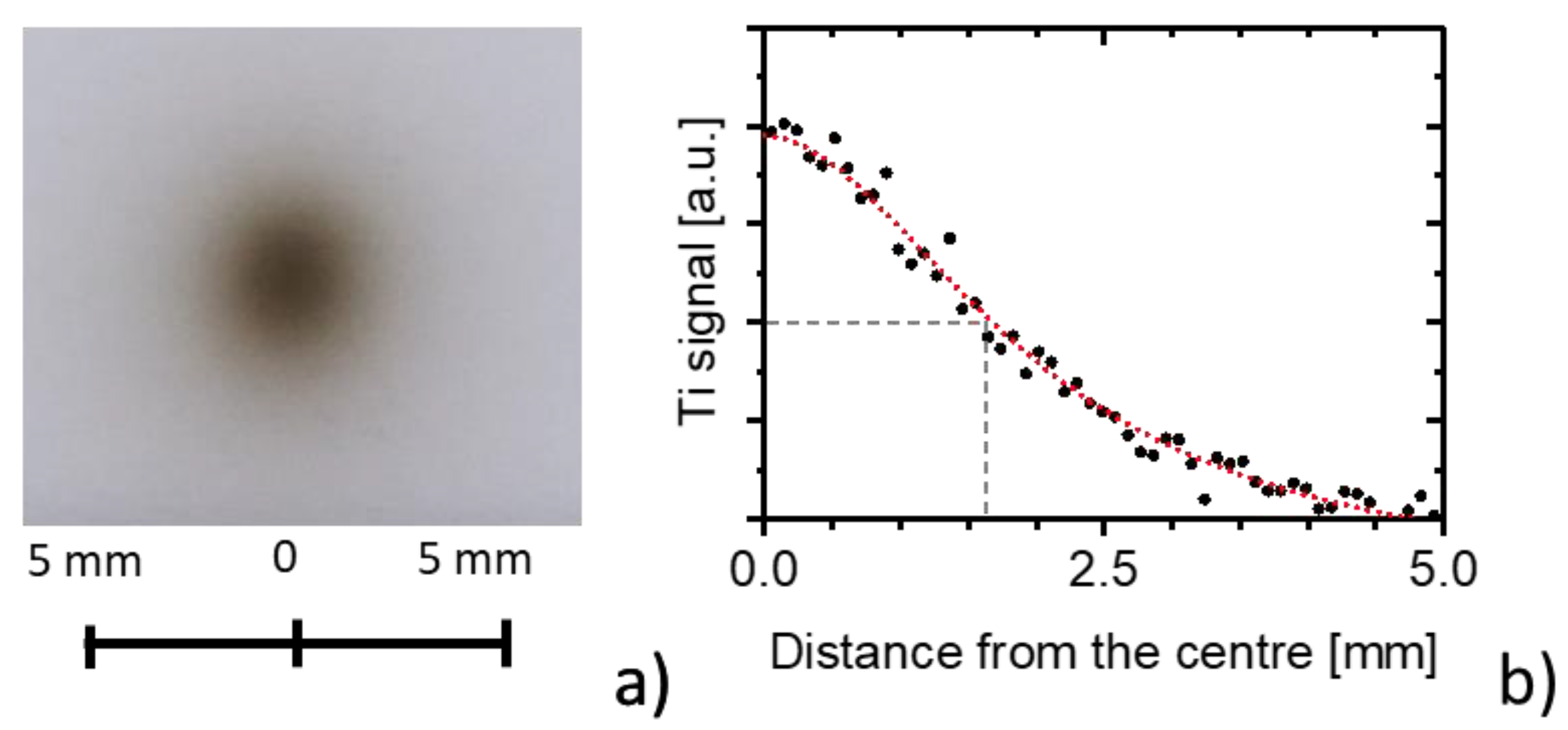
The first step of this study was the investigation of properties of nanoparticle films prepared in a standard configuration, i.e., deposited at zero tilting (tilting angle α = 0°). As can be seen in Figure 2a, where a photograph of Ti NPs deposited for 1 min onto a glass slide is presented, the resulting shape of the nanoparticle film is circular, with a radius of approximately 2.5 mm. Moreover, EDS mapping revealed that the profile of the deposit is approximately Lorentzian with a half-width at the full maxima of 1.65 mm (Figure 2b).
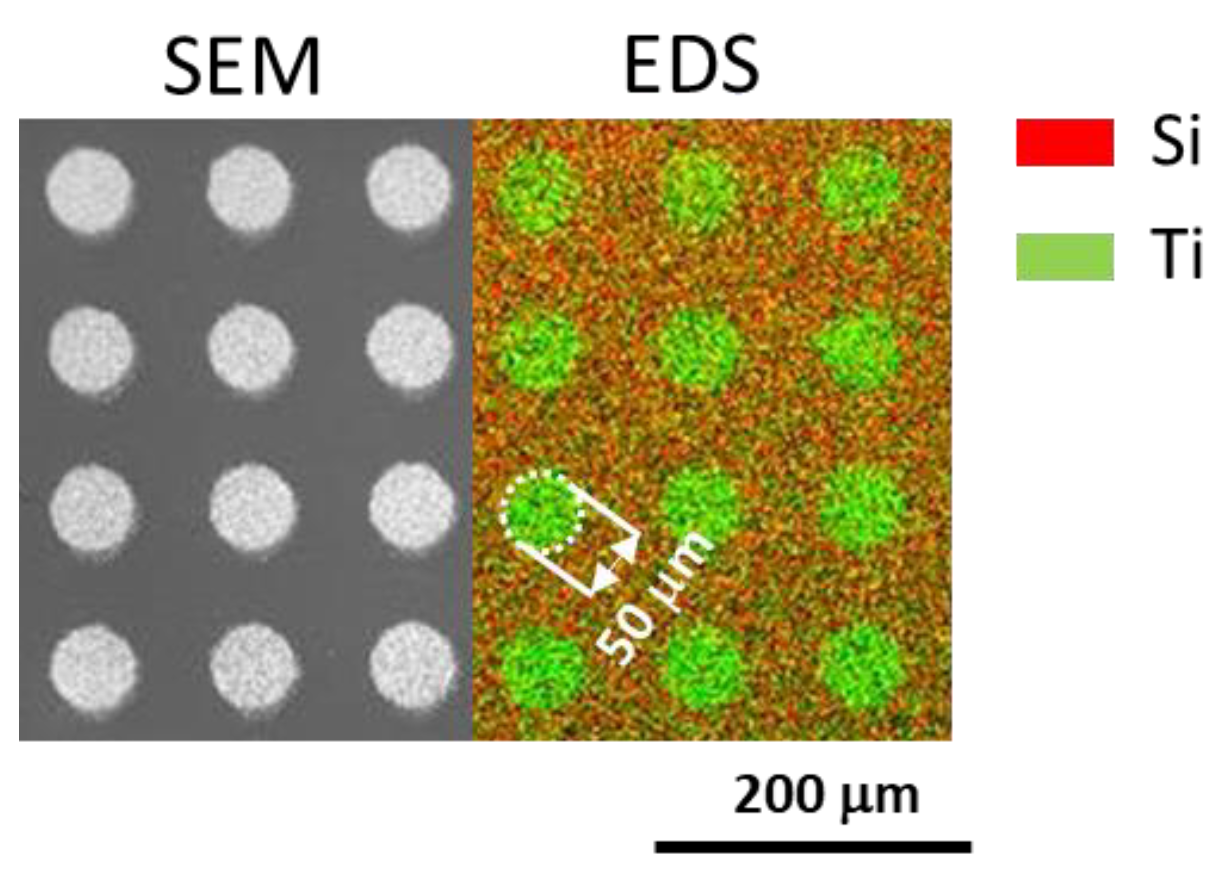
Considering the distance between the substrate and output orifice and the radius of the orifice, the knowledge of the size of the deposited spot allows determining the divergence of the cone formed by the nanoparticles leaving the aggregation chamber, which is 0.3°. This result clearly confirms the good directionality of the nanoparticle deposition with a focusing orifice, i.e., a characteristic that paves the way for the application of m-GAS systems for the fabrication of nanoparticle patterns. To demonstrate this possibility, a Si mask with an array of circular openings (50 µm in diameter, center-to-center distance of 100 µm) was introduced 1 mm above the substrate to be coated. As can be seen in Figure 3, where the SEM image and 2D EDS elemental map of the resulting sample is presented, the initial pattern is well reproduced in the deposited samples.
Related to the morphology of as-deposited Ti nanoparticles, i.e., not annealed nanoparticles, they were found to have a spherical shape with a mean diameter of 27 ± 2 nm (Figure 4), i.e., a morphology identical to the one reported for m-GAS based on a 2-inch magnetron for higher aggregation pressures and magnetron currents [27]. At this point, it is worth noting that the size of the nanoparticles stays constant independently of the position on the deposit. Although certain size selections due to the drag forces acting in the area close to the exit orifice of the aggregation chamber may occur, this effect is, in our case, limited by the focusing orifice. The annealing of Ti nanoparticle films subsequently resulted in a slight increase in their size (mean diameter 31 ± 2 nm), which may be attributed to the heat-induced oxidation of Ti. However, the heat treatment, at least at the temperature used in this study, had no impact on the shapes of individual nanoparticles that preserved their spherical shape, as can be seen in Figure 4.
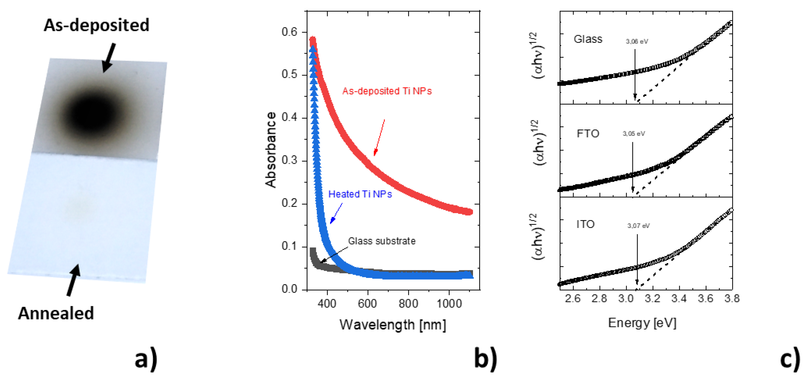
In contrast to the morphology of Ti nanoparticles which was found not to be largely influenced by the thermal treatment, the annealing had a dramatic impact on the appearance of nanoparticle films; the initially dark grey nanoparticle films changed into transparent ones after the annealing step (Figure 5a).
To quantify the observed changes in the optical properties, UV-Vis spectra of as-deposited and annealed Ti nanoparticle films have been measured. These are presented in Figure 5b for the case of the glass substrate (the UV-Vis spectrum of uncoated glass is presented as well for the comparison). As can be seen, the absorbance of as-deposited NPs increases gradually with the decrease in the wavelength of the incoming light, i.e., the tendency common for metallic films. In contrast, the annealed samples exhibit good transparency down to approximately 500 nm and an abrupt increase of the absorbance for lower wavelengths. In this highly absorbing region, the optical band gap can be estimated using Tauc’s plots. As can be seen in Figure 5c, the annealed samples exhibit an optical band gap of 3.05–3.07 eV. Despite neglecting the possible light scattering on nanoparticles, the measured value of the optical band gap is in good agreement with the values reported for rutile and brookite TiO2 nanoparticles (~3.0–3.13 eV) and slightly lower as compared to the value of the optical band gap of anatase (~3.2 eV) [28]. The existence of the optical band gap, in addition, suggests the phase transformation of initially metallic Ti nanoparticles to crystalline TiO2 ones. Furthermore, it is important to stress that the value of the optical band gap is independent of the underlying substrate material, which clearly shows that both the deposition and heat-induced crystallization are, in our case, substrate-independent processes and may be applied to produce highly porous TiO2 nanoparticle films on transparent and conductive ITO and FTO substrates commonly used in the energy harvesting applications.
To confirm the crystallization of annealed Ti nanoparticle films, the samples have been characterized by XRD. A diffraction pattern of annealed sample is presented in Figure 6. As can be seen, different crystallographic peaks are present that correspond to the rutile and brookite phases with a ratio of approximately 1:2. According to the analysis of the XRD pattern, the lattice constants derived for the tetragonal rutile (a = 4.589 ± 0.001 Å, c = 2.951 ± 0.002 Å) and orthorhombic brookite (a = 9.184 ± 0.029 Å, b = 5.472 ± 0.021 Å, c = 5.099 ± 0.012 Å) are in a good match with the reported values for these two phases [29,30]. Furthermore, the sizes of crystallites, i.e., coherently diffracting domains, were found to be 4.2 ± 0.3 nm in the case of rutile and 2.8 ± 0.2 nm for brookite. Considering the mean sizes of TiO2 nanoparticles, which were 31 ± 0.2 nm (see Figure 4), these results suggest that the nanoparticles are heterogenous with small crystalline grains.

3.2. Influence of the Tilting Angle on the Morphology of Produced Nanoparticle Films

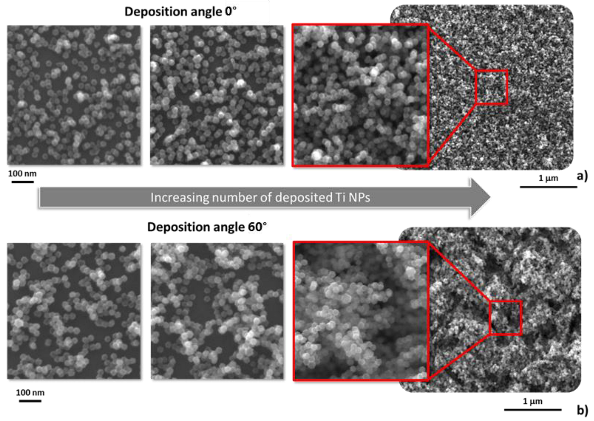
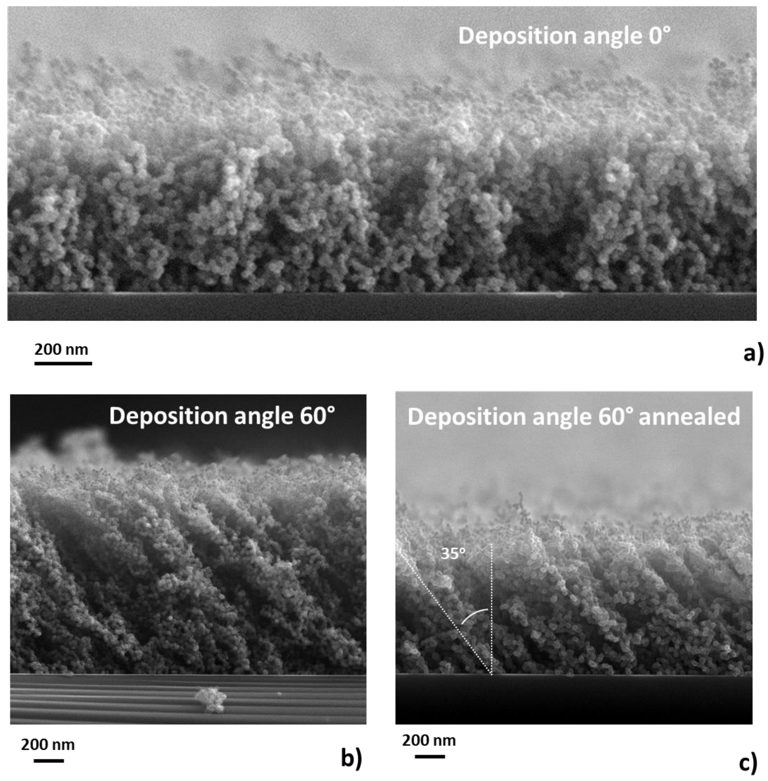
In order to investigate the impact of tilting angle on the morphology of TiO2 nanoparticle films, samples with different fluences of Ti nanoparticles were deposited at tilting angles α 0° and 60°. As can be seen in Figure 7a, in the case of the zero tilting angle, the substrate is initially covered by individual nanoparticles. An increase in the number of deposited nanoparticles leads to the formation of porous nanoparticle film with no preferential structuring. In contrast, in the case of deposition at the tilting angle of 60°, the nanoparticles tend to form randomly distributed structures on the substrate, observable even for the low number of deposited nanoparticles (see Figure 7b). The difference between the depositions performed at 0° and 60° tilting angles is even more evident from the SEM images of the cross-section of resulting films presented in Figure 8, while no preferential direction of the growth of nanoparticle film was observed for zero tilting deposition (Figure 8a), the Ti nanoparticles were organized into clearly visible inclined columns when the deposition was performed at the tilting angle of 60° (Figure 8b). The formation of the later structures, which resemble columnar structures produced by PVD techniques at oblique angles and low-pressure conditions [11,12], relates to the shadowing effect: the nanoparticles deposited at the earliest stages of deposition create a “shadow” behind them that subsequently prevents the deposition of any further NPs within these “shadowed” regions. As a result, the growing film is characterized by separated columns composed of individual nanoparticles. However, the formation of columnar structures is possible only if two conditions are fulfilled, (i) the nanoparticles are deposited in a ballistic regime, and (ii) there is a good directionality of the incoming nanoparticles. While the ballistic deposition regime is a feature typical for the soft-landing nanoparticles produced by gas aggregation sources as soon as a monolayer of nanoparticles is formed [31], good directionality of the incoming nanoparticle beam is assured using a focusing orifice, as it was demonstrated in Section 3.1. Noteworthy also is the fact that the angle of the growing nanoparticle columns is lower as compared to the titling angle. This effect, also known from the glancing angle deposition using atoms, can be described by a heuristic tangent rule, in which the relation between the tilting angle α and the growth angle β is [32]:
tan ( α ) = 2 · tan ( β )
Considering that in our case, the angle α equals 60°, the experimentally obtained angle β (35°) agrees well with the theoretical value derived by Equation (2) and is in line with the recent results reported for vanadium nanoparticles deposited for tilting angles 40°, 60° and 70° [15]. However, the reason for the differences in deposition and growth angles is still under debate. First, one has to consider that the deposition source is not strictly punctual, and the nanoparticles do not have a single angular direction. In addition, the short-range interaction that occurs between incoming nanoparticles and a substrate may change the trajectories of deposited nanoparticles close to the substrate and cause the growth of columns at an angle different to the angle at which nanoparticles arrive at the substrate (so-called surface trapping mechanism) [12].
Finally, from the point of view of possible applications, an important finding is that the columnar and porous structure of Ti nanoparticle films is maintained after annealing the deposited films. This is documented in Figure 8c.

4. Discussion

The results presented in this study may be summarized as follows. First of all, we have demonstrated the good directionality of the deposition process of Ti nanoparticles employing a magnetron-based gas aggregation source. It was shown that under the deposition conditions used in this study, i.e., using a focusing orifice, the beam of the nanoparticles leaving the aggregation chamber is characterized by very low divergence (0.3°). This allows not only to deposit highly porous Ti nanoparticle films but also paves the way for the production of more complex patterned surfaces using a solid mask, in which the nanoparticles are deposited solely on the desired positions on the substrate. In other words, combining the nanoscale character of the deposited nanoparticles (around 30 nm) with micrometer scale patterning processes is possible. Furthermore, the directionality of the deposition process allows, in combination with the substrate tilting, the fabrication of the Ti nanoparticle films with well-developed columnar architecture in the same way as in the more common approach based on the atomistic PVD glancing angle deposition. The possibility to vary the morphology of the nanoparticle films represents an interesting and simple strategy to tailor the porosity of the resulting coatings and, hence, to control their functionality. At this point, it is worth noting that the lateral size of nanoparticle films is rather limited in this study, and only areas having the size in the order of units of mm2 were coated with porous nanoparticle films. However, this drawback could be overcome, e.g., by using slot-like orifices or by the movement of the substrates with respect to the nanoparticle beam. Furthermore, our study revealed that the deposited Ti nanoparticle films might be converted by annealing in the air to semi-transparent TiO2 ones with an optical band gap close to 3.0 eV. Importantly, the heat-induced crystallization process does not compromise the morphology of the coatings that maintain the character of the film comprised of individual nanoparticles. Finally, it was shown that the proposed strategy for the preparation of nanoparticle-based TiO2 nanostructured coatings is compatible with the substrate materials (ITO, FTO) commonly used as transparent electrodes in the case of water-splitting systems or solar cells.
In conclusion, it can be stated that the studied possibility of producing semi-transparent nanoparticle TiO2 films brings certain key advantages as compared to the techniques that employ chemical processes. In comparison with sol-gel and anodization techniques, the approach based on the utilization of m-GAS systems is a full precursor and solvent-free process and can be thus considered as a ‘green’ alternative to the aforementioned techniques. In addition, the physical nature of the fabrication process limits the necessity of the removal of solvent/precursor residuals as well as handling them and subsequent rather cost- and time-consuming purification steps. Finally, although the procedure involves a relatively long annealing step (120 min in this study), which is necessary for the phase transformation of Ti into TiO2, it can still be considered time effective. At this point, it is important to stress that the annealing step may be performed for a larger number of samples at once, significantly reducing the overall processing time per sample. These advantageous features, i.e., the simplicity of the production step, the possibility to form patterned nanoparticles films composed of high-purity nanoparticles with well-defined size, the possibility to change the architecture of mesoporous TiO2 films, the solvent-free and linker-free character of the fabrication process as well as its compatibility with the commonly used transparent and conductive substrates, may stimulate new progress in the field of photo-catalysis, (bio)sensing or energy harvesting, especially if the technical limits with the size of deposited coatings will be solved. Further research direction to expand the application potential of nanostructured TiO2 films represents the possibility of controlling the crystalline phase of TiO2 nanoparticles, e.g., by tuning the annealing step, and their optical band gap, e.g., by their doping.

Author Contributions

Conceptualization, methodology, supervision, writing—review and editing, funding O.K.; writing—original draft preparation, investigation, A.K. and A.H. All authors have read and agreed to the published version of the manuscript.

Funding

This research was funded by the Czech Science Foundation, grant number GAČR 21-05030K.

Institutional Review Board Statement

Not applicable.

Informed Consent Statement

Not applicable.

Data Availability Statement

The data presented in this study are available on request from the corresponding author.

Acknowledgments

We would like to thank colleagues from the Department of Condensed Matter Physics for their support in the interpretation of the XRD patterns.

Conflicts of Interest

The authors declare no conflict of interest.

References

  1. Jafari, S.; Mahyad, B.; Hashemzadeh, H.; Janfaza, S.; Gholikhani, T.; Tayebi, L. Biomedical Applications of TiO2 Nanostructures: Recent Advances. Int. J. Nanomed. 2020, 15, 3447–3470. [Google Scholar] [CrossRef] [PubMed]
  2. Ali, I.; Suhail, M.; Alothman, Z.A.; Alwarthan, A. Recent Advances in Syntheses, Properties and Applications of TiO2 Nanostructures. RSC Adv. 2018, 8, 30125–30147. [Google Scholar] [CrossRef] [PubMed] [Green Version]
  3. Bavykin, D.V.; Friedrich, J.M.; Walsh, F.C. Protonated Titanates and TiO2 Nanostructured Materials: Synthesis, Properties, and Applications. Adv. Mater. 2006, 18, 2807–2824. [Google Scholar] [CrossRef]
  4. Ramanavicius, S.; Jagminas, A.; Ramanavicius, A. Gas Sensors Based on Titanium Oxides (Review). Coatings 2022, 12, 699. [Google Scholar] [CrossRef]
  5. Camposeco, R.; Castillo, S.; Navarrete, J.; Gomez, R. Synthesis, Characterization and Photocatalytic Activity of TiO2 Nanostructures: Nanotubes, Nanofibers, Nanowires and Nanoparticles. Catal. Today 2016, 266, 90–101. [Google Scholar] [CrossRef]
  6. Lin, Y.; Wu, G.S.; Yuan, X.Y.; Xie, T.; Zhang, L.D. Fabrication and Optical Properties of TiO2 Nanowire Arrays Made by Sol Gel Electrophoresis Deposition into Anodic Alumina Membranes. J. Phys. Condenes. Matter 2003, 15, 2917. [Google Scholar] [CrossRef]
  7. Miao, L.; Tanemura, S.; Toh, S.; Kaneko, K.; Tanemura, M. Fabrication, Characterization and Raman Study of Anatase-TiO2 Nanorods by a Heating-Sol-Gel Template Process. J. Cryst. Growth 2004, 264, 246–252. [Google Scholar] [CrossRef]
  8. Kouao, D.S.; Grochowska, K.; Siuzdak, K. The Anodization of Thin Titania Layers as a Facile Process towards Semitransparent and Ordered Electrode Material. Nanomaterials 2022, 12, 1131. [Google Scholar] [CrossRef]
  9. Macak, J.M.; Tsuchiya, H.; Ghicov, A.; Yasuda, K.; Hahn, R.; Bauer, S.; Schmuki, P. TiO2 Nanotubes: Self-Organized Electrochemical Formation, Properties and Applications. Curr. Opin. Solid State Mater. Sci. 2007, 11, 3–18. [Google Scholar] [CrossRef]
  10. Hanif, M.B.; Sihor, M.; Liapun, V.; Makarov, H.; Monfort, O.; Motola, M. Porous vs. Nanotubular Anodic TiO2: Does the Morphology Really Matters for the Photodegradation of Caffeine? Coatings 2022, 12, 1002. [Google Scholar] [CrossRef]
  11. Hawkeye, M.M.; Brett, M.J. Glancing Angle Deposition: Fabrication, Properties, and Applications of Micro- and Nanostructured Thin Films. J. Vac. Sci. Technol. A 2007, 25, 1317–1335. [Google Scholar] [CrossRef]
  12. Barranco, A.; Borras, A.; Gonzalez-Elipe, A.R.; Palmero, A. Perspectives on Oblique Angle Deposition of Thin Films: From Fundamentals to Devices. Prog. Mater. Sci. 2016, 76, 59–153. [Google Scholar] [CrossRef] [Green Version]
  13. Haberland, H.; Karrais, M.; Mall, M.; Thurner, Y. Thin Films from Energetic Cluster Impact: A Feasibility Study. J. Vac. Sci. Technol. A 1992, 10, 3266–3271. [Google Scholar] [CrossRef]
  14. Kratochvíl, J.; Kuzminova, A.; Kylián, O.; Biederman, H. Comparison of Magnetron Sputtering and Gas Aggregation Nanoparticle Source Used for Fabrication of Silver Nanoparticle Films. Surf. Coat. Technol. 2015, 275, 296–302. [Google Scholar] [CrossRef]
  15. Hanková, A.; Kuzminova, A.; Hanuš, J.; Košutová, T.; Solař, P.; Kousal, J.; Kylián, O. Nanostructured and Columnar Vanadium and Vanadium Oxides Films Synthesized by Means of Magnetron-Based Gas Aggregation Source. Surf. Coat. Technol. 2022, 431, 128015. [Google Scholar] [CrossRef]
  16. Ayesh, A.I.; Qamhieh, N.; Ghamlouche, H.; Thaker, S.; El-Shaer, M. Fabrication of Size-Selected Pd Nanoclusters Using a Magnetron Plasma Sputtering Source. J. Appl. Phys. 2010, 107, 034317. [Google Scholar] [CrossRef]
  17. Acsente, T.; Negrea, R.F.; Nistor, L.C.; Logofatu, C.; Matei, E.; Birjega, R.; Grisolia, C.; Dinescu, G. Synthesis of Flower-like Tungsten Nanoparticles by Magnetron Sputtering Combined with Gas Aggregation. Eur. Phys. J. D 2015, 69, 60097. [Google Scholar] [CrossRef]
  18. Kratochvíl, J.; Prysiazhnyi, V.; Dyčka, F.; Kylián, O.; Kúš, P.; Sezemský, P.; Štěrba, J.; Straňák, V. Gas Aggregated Ag Nanoparticles as the Inorganic Matrix for Laser Desorption/Ionization Mass Spectrometry. Appl. Surf. Sci. 2021, 541, 148469. [Google Scholar] [CrossRef]
  19. Gracia-Pinilla, M.; Martínez, E.; Vidaurri, G.S.; Pérez-Tijerina, E. Deposition of Size-Selected Cu Nanoparticles by Inert Gas Condensation. Nanoscale Res. Lett. 2010, 5, 180–188. [Google Scholar] [CrossRef] [Green Version]
  20. Drabik, M.; Choukourov, A.; Artemenko, A.; Polonskyi, O.; Kylian, O.; Kousal, J.; Nichtova, L.; Cimrova, V.; Slavinska, D.; Biederman, H. Structure and Composition of Titanium Nanocluster Films Prepared by a Gas Aggregation Cluster Source. J. Phys. Chem. C 2011, 115, 20937–20944. [Google Scholar] [CrossRef]
  21. Polonskyi, O.; Ahadi, A.M.; Peter, T.; Fujioka, K.; Abraham, J.W.; Vasiliauskaite, E.; Hinz, A.; Strunskus, T.; Wolf, S.; Bonitz, M.; et al. Plasma Based Formation and Deposition of Metal and Metal Oxide Nanoparticles Using a Gas Aggregation Source. Eur. Phys. J. D 2018, 72, 80419. [Google Scholar] [CrossRef]
  22. Shelemin, A.; Kylián, O.; Hanuš, J.; Choukourov, A.; Melnichuk, I.; Serov, A.; Slavínská, D.; Biederman, H. Preparation of Metal Oxide Nanoparticles by Gas Aggregation Cluster Source. Vacuum 2015, 120, 162–169. [Google Scholar] [CrossRef]
  23. Popok, V.N.; Jeppesen, C.M.; Fojan, P.; Kuzminova, A.; Hanuš, J.; Kylián, O. Comparative Study of Antibacterial Properties of Polystyrene Films with TiOx and Cu Nanoparticles Fabricated Using Cluster Beam Technique. Beilstein J. Nanotechnol. 2018, 9, 861–869. [Google Scholar] [CrossRef] [PubMed] [Green Version]
  24. Košutová, T.; Horák, L.; Pleskunov, P.; Hanuš, J.; Nikitin, D.; Kúš, P.; Cieslar, M.; Gordeev, I.; Burazer, S.; Choukourov, A.; et al. Thermally-Driven Morphogenesis of Niobium Nanoparticles as Witnessed by in-Situ x-Ray Scattering. Mater. Chem. Phys. 2022, 277, 125466. [Google Scholar] [CrossRef]
  25. Matěj, Z.; Kužel, R.; Nichtová, L. XRD Total Pattern Fitting Applied to Study of Microstructure of TiO2 Films. Powder Diffr. 2010, 25, 125–131. [Google Scholar] [CrossRef]
  26. Makuła, P.; Pacia, M.; Macyk, W. How To Correctly Determine the Band Gap Energy of Modified Semiconductor Photocatalysts Based on UV-Vis Spectra. J. Phys. Chem. Lett. 2018, 9, 6814–6817. [Google Scholar] [CrossRef] [PubMed] [Green Version]
  27. Drábik, M.; Choukourov, A.; Artemenko, A.; Kousal, J.; Polonskyi, O.; Solaå, P.; Kylián, O.; Matoušek, J.; Pešička, J.; Matolínová, I.; et al. Morphology of Titanium Nanocluster Films Prepared by Gas Aggregation Cluster Source. Plasma Processes Polym. 2011, 8, 640–650. [Google Scholar] [CrossRef]
  28. Henderson, M.A. A Surface Science Perspective on TiO2 Photocatalysis. Surf. Sci. Rep. 2011, 66, 185–297. [Google Scholar] [CrossRef]
  29. Baur, W.H. Atomabstände Und Bindungswinkel Im Brookit, TiO2. Acta Crystallogr. 1961, 14, 214–216. [Google Scholar] [CrossRef]
  30. Cromer, D.T.; Herrington, K. The Structures of Anatase and Rutile. J. Am. Chem. Soc. 1955, 77, 4708–4709. [Google Scholar] [CrossRef]
  31. Borghi, F.; Podestà, A.; Piazzoni, C.; Milani, P. Growth Mechanism of Cluster-Assembled Surfaces: From Submonolayer to Thin-Film Regime. Phys. Rev. Appl. 2018, 9, 044016. [Google Scholar] [CrossRef] [Green Version]
  32. Dirks, A.G.; Leamy, H.J. Columnar Microstructure in Vapor-Deposited Thin Films. Thin Solid Films 1977, 47, 219–233. [Google Scholar] [CrossRef]
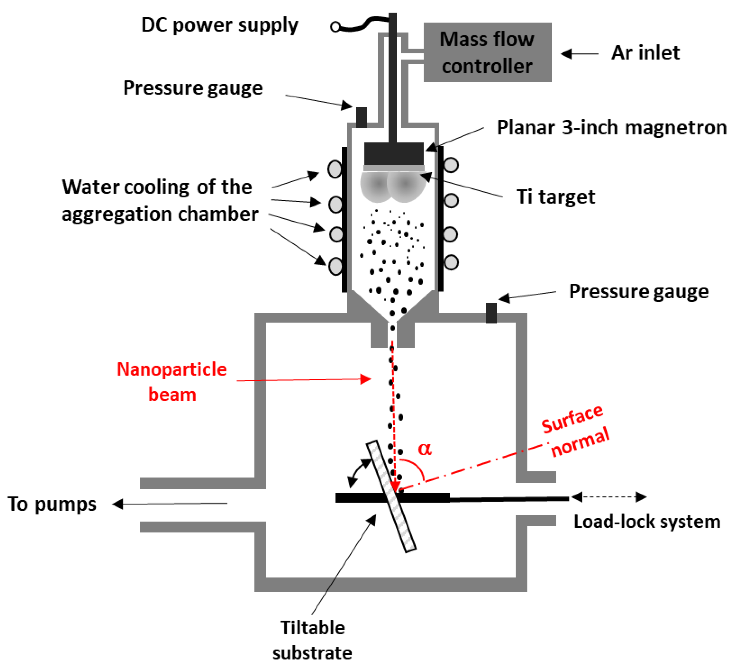
Figure 1. Schematic representation of the deposition set-up.
Coatings 13 00051 g001
Figure 2. (a) Image of the spot of deposited Ti nanoparticles and (b) profile of Ti signal on the deposited spot as measured by EDS. The deposition time was 1 min.
Coatings 13 00051 g002
Figure 3. SEM (left) and EDS maps (right) of patterned Ti nanoparticle films deposited onto a Si wafer through a Si mask with an array of circular openings (50 µm in diameter). The false red color corresponds to Si; the green color corresponds to Ti.
Coatings 13 00051 g003
Figure 4. SEM images of (a) as-deposited and (b) annealed Ti nanoparticles. (c) Comparison of size histograms of as-deposited and annealed Ti nanoparticles.
Coatings 13 00051 g004
Figure 5. (a) Photo of as-deposited and annealed Ti nanoparticle films. (b) UV-Vis spectra of as-deposited and annealed Ti nanoparticle films deposited on a glass substrate. For comparison, the UV-Vis spectrum of an uncoated glass substrate is also presented. (c) Tauc’s plots of annealed Ti nanoparticle films deposited onto glass (top), FTO-coated glass (middle), and ITO-coated glass (bottom). The deposition time was 3 min, the annealing temperature was 450 °C, and the annealing time was 120 min.
Coatings 13 00051 g005
Figure 6. XRD pattern of annealed nanoparticle film (blue circles) and the fit of the experimentally obtained pattern (red line). In the case of crystallographic peaks of rutile, individual crystallographic planes are indicated. In contrast, due to the numerous peaks that correspond to brookite, only the positions of the individual peaks are indicated by red lines at the bottom of the figure for better clarity. The deposition time was 3 min, the annealing temperature 450 °C, and the annealing time 120 min.
Coatings 13 00051 g006
Figure 7. Top-view SEM images of growing Ti nanoparticle films deposited at (a) zero tilting angle and (b) tilting angle of 60°.
Coatings 13 00051 g007
Figure 8. Cross-section SEM images of Ti nanoparticle films deposited at (a) zero tilting angle and (b) tilting angle of 60°. (c) Cross-section SEM image of the sample deposited at the tilting angle of 60° after the annealing.
Coatings 13 00051 g008
Disclaimer/Publisher’s Note: The statements, opinions and data contained in all publications are solely those of the individual author(s) and contributor(s) and not of MDPI and/or the editor(s). MDPI and/or the editor(s) disclaim responsibility for any injury to people or property resulting from any ideas, methods, instructions or products referred to in the content.