Article

Abrasive and Erosive Wear of TI6Al4V Alloy with Electrospark Deposited Coatings of Multicomponent Hard Alloys Materials Based of WC and TiB2

1
Institute of Soil Science Agrotechnologies and Plant Protection “N. Pushkarov”, Agricultural Academy, 1331 Sofia, Bulgaria
2
Faculty of Industrial Technology, Technical University of Sofia, 1000 Sofia, Bulgaria
*
Author to whom correspondence should be addressed.
Coatings 2023, 13(1), 215; https://doi.org/10.3390/coatings13010215
Submission received: 15 December 2022 / Revised: 11 January 2023 / Accepted: 13 January 2023 / Published: 16 January 2023
(This article belongs to the Special Issue Coatings and Surface Modification for Tribological Applications)

Abstract

:
In the present work, abrasive and erosive wear of wear-resistant composite coatings with a complex structure and different phase compositions deposited on titanium surfaces was studied. The coatings were obtained by electrospark deposition (ESD) using two types of hard-alloy compositions: WC–TiB2–B4C–Co–Ni–Cr–Si–B and TiB2–TiAl reinforced with dispersed nanoparticles of ZrO2 and NbC. The influence of the ESD process parameters on the roughness, thickness, composition, structure and coefficient of friction of the coated surfaces was investigated, and their role in protecting the titanium surfaces from wear was clarified. Dense coatings with the presence of newly formed wear-resistant phases and crystalline-amorphous structures were obtained, with roughness, thickness and microhardness that can be varied by the ESD modes in the range Ra = 2.5 ÷ 4.5 µm, δ = 8 ÷ 30 µm and HV 8.5 ÷ 14.0 GPa. The new coatings were found to reduce the abrasive and erosive wear of the coated surfaces by up to four times. The influence of the geometric characteristics, composition and structure of coatings on the wear intensity and wear resistance of coatings was studied.

1. Introduction

At the present stage, the most common tribological resource for improving the low surface hardness and low friction and wear characteristics of titanium and the most popular titanium alloy Ti6Al4V applied both in engineering and as a biocompatible material are surface modification methods and technologies and application of wear-resistant coatings [1,2,3]. Different methods and means of depositing coatings are currently available: electrochemical, galvanic, thermochemical, vacuum, electrophysical, etc. [3,4,5,6,7,8,9], which may not always provide all the requirements for geometric accuracy and characteristics of the surface layer due to their natural technological limitations, or due to the complexity of technologies and equipment, high production costs and also due to the appearance of some adverse effects on titanium alloys such as insufficient adhesion to the substrate, oxidation, annealing, or thermal deformation. Among these methods, electrospark deposition (ESD) [10,11,12] is distinguished by its low cost, the versatility of the technology, simplicity, compactness and accessibility of the equipment. This method provides a fast and easy local coating deposition on products of various shapes and sizes and minimal substrate heating. ESD provides metallurgical bonding and much better adhesion between the coating and the substrate compared to other known methods [12,13,14]. It is widely known that the phase and structural state of the applied coatings, their properties and their wear resistance depends on the parameters of the ESD regime and the type of deposition materials. By changing the process parameters and the composition of the deposition electrodes for ESD, it is possible to regulate the micro metallurgical processes in the discharge zone, synthesize new chemical compounds and form complex composite coatings of intermetallic compounds, carbides, borides, nitrides, oxides. However, at this stage, these possibilities have not yet been fully explored. Electrodes of classical hard alloys based on WC [13,15,16,17], TiC and TiN [11,14,18,19] are most often used in order to reinforce titanium alloys, which are not always effective and do not always provide the necessary complex of properties for protection of the titanium surfaces [18,19,20]. Many researchers claim that coatings made of multi-component materials are more effective because they allow using the advantages of each of the components [11,12,18,19,20,21,22]. Therefore, in order to improve the efficiency of this simple, accessible and cheap method and of coated titanium alloys, it is necessary to use new compositions of electrode materials and to optimize the properties of the coatings and their deposition technology.
In this regard, the present work is aimed at improving the surface hardness and wear resistance of titanium alloys through the ESD of coatings of new multi-component electrode materials. The subject of the work is the creation of coatings from new hard alloy multicomponent materials based on WC and TiB2 and the study of the influence of the parameters of the ESD mode on the composition, structure and properties of the coatings, as well as on the characteristics of abrasive and erosive wear, which are among the most common in practice types of wear of the titanium alloys.
The study of the general laws and physico-mechanical properties of the formed layer and their influence on the mechanism and wear kinetics will allow for determining ways for controlled management of the operational properties of the treated surfaces and for developing technological variants for ESD. The aim of the work is to investigate the wear characteristics of titanium surfaces with electrospark coatings of new composite electrode materials based on carbides and borides with a metal soldering mass Co-Ni-Cr-B-Si and additives of super hard materials and nanoparticles at dry friction and at interaction with an air jet carrying abrasive particles, as a function of process parameters, topography, composition and structure of coatings. To evaluate the possibilities of using these electrodes to improve the tribological properties of titanium alloys and to be determined appropriate parameters of the ESD process to obtain coatings with improved hardness, wear resistance and triboefficiency.

2. Materials and Methods

2.1. Experimental Procedures

-
Substrate. Model plates of titanium alloy Ti6Al4V (GR5) and of technical titanium Ti-GR2 (AISI UNS R R56200 and R50400) with sizes 12 mm × 12 mm × 4 mm were used for the substrate.
-
Electrodes
Two types of electrode materials with the following designations and compositions were selected for the present studies:
-
KW10T10B10—48%WC + 12%TiB2 + 10%B4C + 30%(Co-Ni-Cr-B-Si-C),- created by us [11].
The selected composition of the solid and plastic parts is different from the known ones in that, in addition to WC, it additionally contains TiB2 and B4C. Boron carbide B4C is a super hard material with extremely high abrasion resistance, but it is brittle. The introduction of the less brittle components tungsten carbide–WC—the most commonly used coating material on titanium with proven efficiency [11,13,15,16,17] and titanium diboride-TiB2 with high hardness, wear resistance and chemical resistance [18,23,24,25], reduces this problem. To avoid the formation of oxide phases that cause brittleness of the deposited layer, B, Si and C have been used [20,21,24,25,26,27]. Boron, in addition to being a deoxidizer, can serve as a donor for the formation of wear-resistant borides. Co, Ni and Cr were used to form a strong matrix for the solid particles to have good adhesion with the titanium substrate and also to improve the transfer and to obtain dense and uniform coatings with higher thickness and wear resistance [11,13,18,20,22,24,25,26];
-
TiB2–TiAlnano (66.7Ti; 20.0Al; 13.3B), developed by self-high-temperature synthesis (SHS) [18,27,28] and dispersedly reinforced with nanoparticles (ZrO2, NbC), [27].
-
Electrospark deposition equipment and modes.
The ESD was performed by a hand-held apparatus, Carbide Hardedge (Aids Electronic Ltd., Watford, UK), with the vibrating movement of the electrode at the following parameters: Short circuit current ≈ 0.8–1.5 A, Voltage U = 80 V, oscillation frequency of the vibrator–100 Hz. The coatings were deposited at pre-optimized modes with capacitances of 5, 10 and 20 µF and with single pulse energy E = C.U2/2, E ≈ 0.02, 0.04 and 0.07 J, respectively, with three electrode passes at a speed of ≈1 ÷ 1.5 mm/s.

2.2. Types of Research, Methodology of Measurements, Research Equipment

The influence of the ESD process parameters on the characteristics of the coatings and the tribological behavior of the coated surfaces in the most common types of wear of titanium alloys (abrasive and erosive) is investigated.
-
The surface roughness parameters Ra, Rz, Rq, Rt and thickness δ of the resulting coatings are measured by using profilometer AR-132B, (Shenzhen Graigar Technology Co., Ltd., Shenzhen, China) at EN ISO 13565-2:1996 and DIN 4776 standards.
-
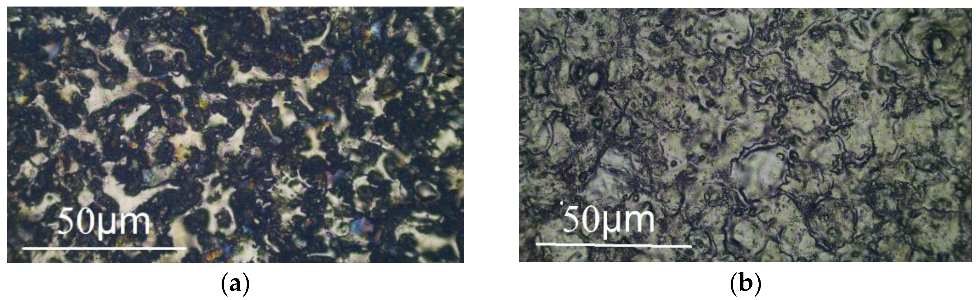
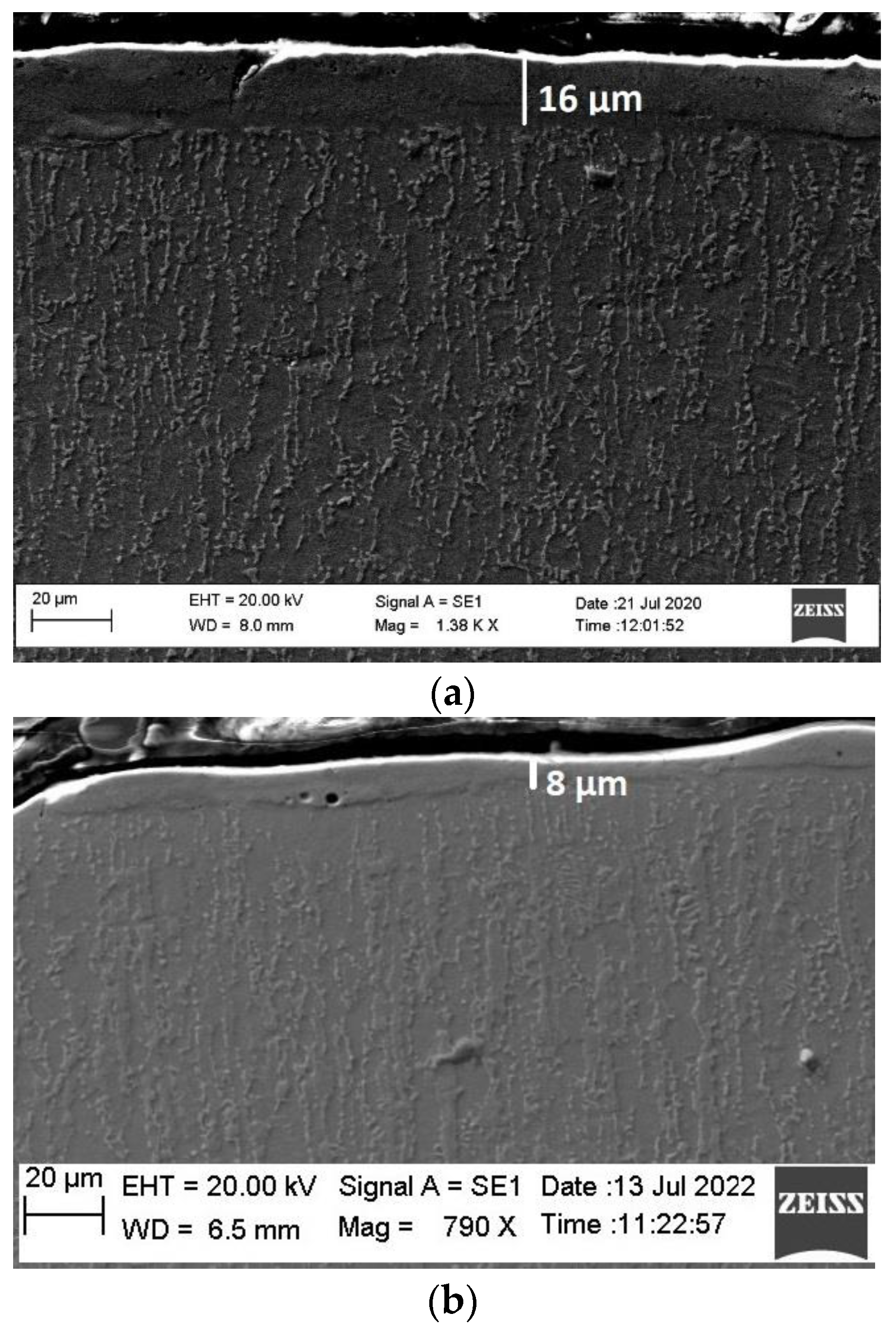
The morphology, topography and microstructural analysis of the ESD layers were examined with optical microscopy (Epytip 2, Carl Zeiss Jena) and scanning electron microscopy (SEM, EVO MA10 Carl Zeiss, Jena, ZEISS Microscopy, Deutschland GmbH).
-
The microhardness HV was measured on the surface of the coatings with a microhardness tester Zwick 4350 (ZwickRoell, GmbH & Co. KG, Ulm, Germany), according to ISO 6506-1: 2014, at a load of 2 N with a Vickers indenter diamond prism.
-
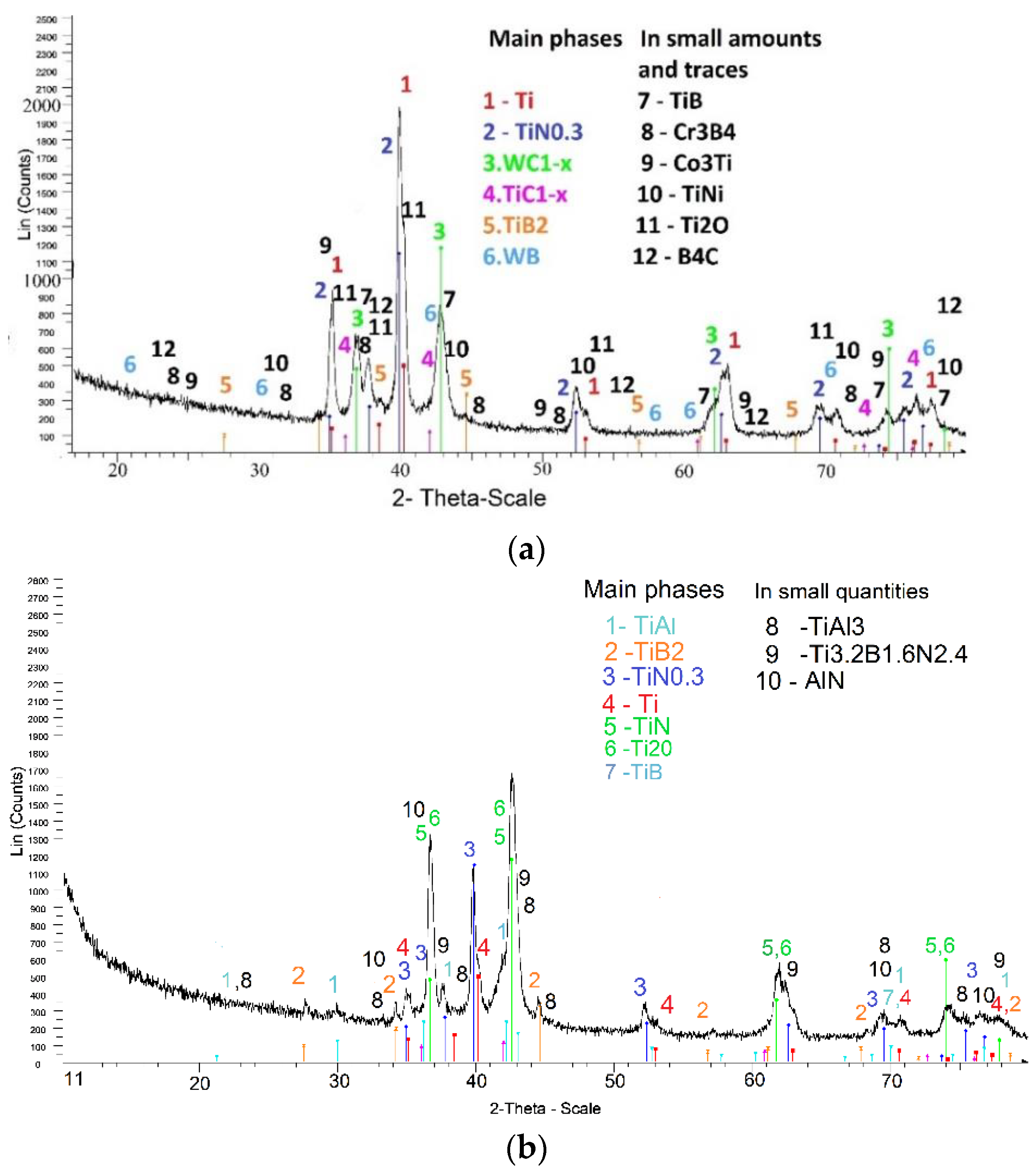
The phase identification was performed with an X-ray diffractometer Bruker D8 Advance (Bruker AXS, Karlsruhe, Germany) in “Cu Kά” radiation.

2.3. Tribological Studies

The scratch tests were performed with a CSM REVETEST Scratch Macrotester equipped with a Rockwell C diamond indenter with a 200 μm tip radius. Progressive load scratching mode with a normal force range of 0 N to 50 N was used at a speed of 10 N/mm. The scratch track was evaluated using optical methods as well as by means of digital-signal records of the coefficient of friction (μ) and tangential force (Ft). The light optical microscopy of the scratch tracks was performed using a Nikon microscope.
Abrasive wear—The abrasion properties and wear resistance of the coatings were investigated by comparative tests of friction with tribotester type “Thumb-on disk” according to the scheme used in [11,24,25] under dry surface friction with hard-fixed abrasive particles and at loads P 10N, Sliding speed–Vc = 0.8 m/s, Abrasive surface–Corund P 1000.
The following wear characteristics were calculated:
-
Mass wear—
m = m 0 m i ,   mg
-
Wear intensity—the amount of wear per unit of friction work:
W = m P L ,
where m is the wear of the solid for the test time, P—the normal load and L—the friction path passed.
-
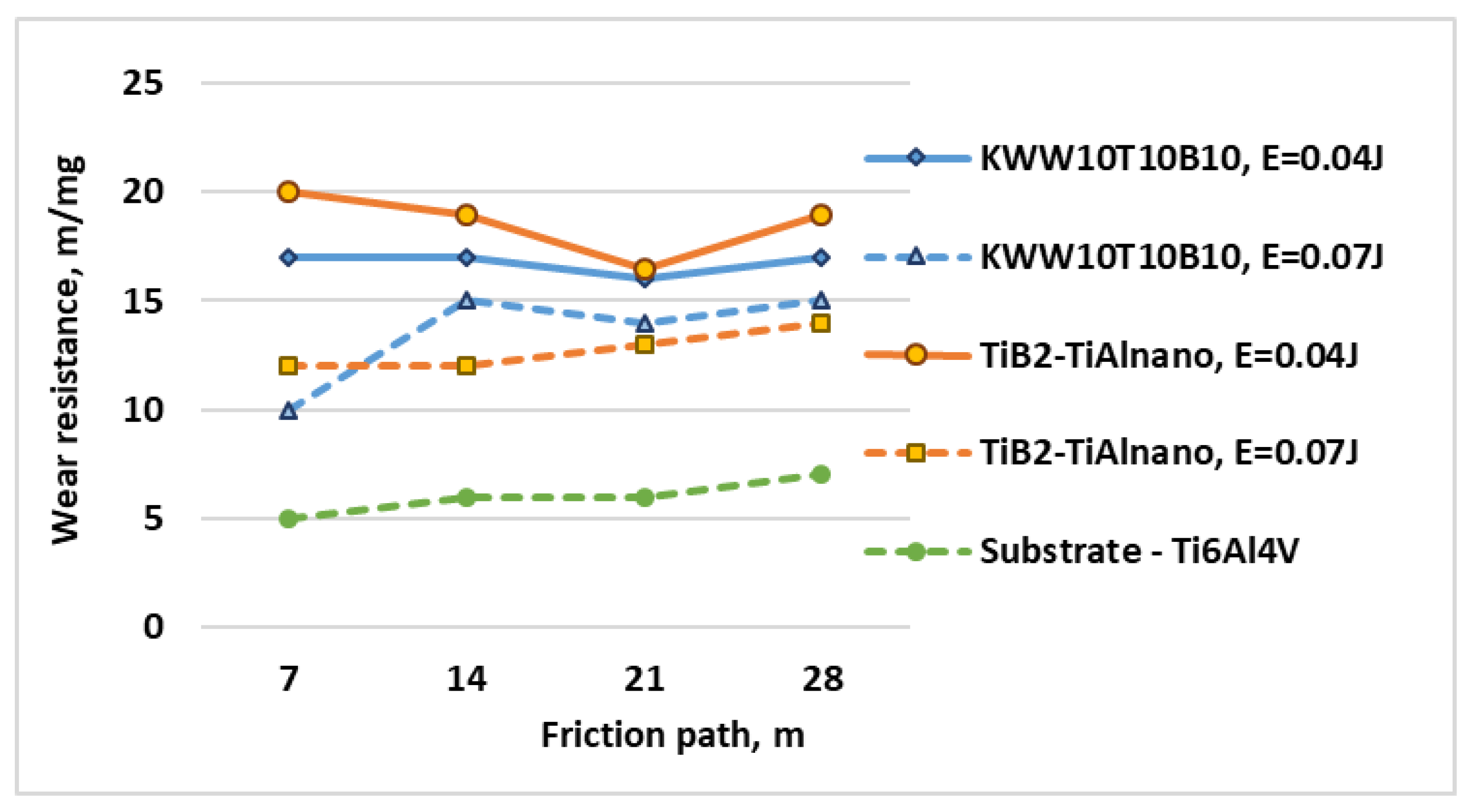
Wear resistance (Wr): Reciprocal value of the wear intensity.
Erosive wear tests—The erosive wear tests were carried out on a stand using a nozzle with an initial diameter of 6 mm according to the scheme used in [29]. The two-phase (solids particles-air) produced working stream was bumped at an angle of 90° into the surface of the test specimen.
The mass erosion wear me was defined as the difference in sample mass before and after the processing.
The mass flow rate m ˙ a of a given abrasive material with mass m a in the device was determined by measuring the time t a for the gravitational flowing out of the abrasive material:
m ˙ a = m a t a ,
The rate of erosion wear was determined by the formula:
m ˙ e = m e / t e ,
where t e is the time duration of the test. The erosion intensity was determined by the formula:
i ˙ e = m ˙ e / m ˙ a , .
The erosion wear resistance I e was defined as a reciprocal value of the erosion intensity.
The erosion parameters are: solid particles material- black corundum (Al2O3) with size—600 μm; air stream pressure—0.1 MPa; particles flow—166.67 g/min; distance between the sample and the nozzle—10 mm; test duration—5 min.
The mass of the samples before and after a given rubbing time was measured with an electronic balance WPS 180/C/2 with an accuracy of 0.1 mg.
The results of each of the above studies are the arithmetic mean of three parallel experiments. The number of measurements of the roughness and thickness of the coatings for each parallel experiment is 5. The number of microhardness measurements for each parallel experiment is 10.

3. Results and Discussion

3.1. Coating Characterization—Roughness, Thickness, Structure and Micro-Hardness

Figure 1 and Figure 2 show the general appearance of the KW10T10B10 and TiB2–TiAlnano electrode coatings. Figure 3 shows metallographic cross-sections. The electrode materials used produced similar coatings in structure but with different quality characteristics, composition and properties.
The results of the microscopic observations show that the surface layers are inhomogeneous, non-uniform, similar in shape and structure with acceptable repeatability of quality characteristics. Individual cracks and micropores are present in all layers amount increases with increasing pulse energy. In the coatings from both electrodes. Rod-shaped and dot-shaped formations are observed in coatings from both types of electrodes, as well as glass-like zones, grains with a complex asymmetrical shape and the typical ESD uneven relief.
It can be seen that the individual coating components of TiB2–TiAlnano electrodes have smaller dimensions and are more densely and uniformly distributed. The coatings are more homogeneous and uniform, which is manifestly due to the nano-sized additives in the composition of this electrode. It is also seen that the increase in pulse energy from 0.04 to 0.07 J leads to an increase in the dimensions of the individual structural components as well as to an increase in the non-uniformity of the coatings.
The average values of surface roughness parameters Ra, Rz, Rq, Rt (at EN ISO 13565-2:1996), the thickness δ and the microhardness HV of coatings obtained are shown in Table 1.
The thickness of the deposited coatings is in the range of 8 ÷ 18 μm, with roughness Ra = 2.3 ÷ 4.3 μm. The data presented in Table 1 indicate that as the pulse energy increases, the thickness of the coatings increases, but their roughness also increases, and their specific values are different for both types of electrodes. The coatings from the WC-based electrode (Figure 1a, Figure 2a and Figure 3a, Table 1) show a greater thickness and a rougher surface. The introduction of boron and boron carbide reduces the erosion resistance of the alloying electrode resulting in an increase in the amount of electrode material transported to the treated surface [11,18,24]. In ESD with TiB2–TiAlnano, the coatings are more uniform, with lower values of the roughness parameters, but also with less thickness. In terms of roughness, uniformity, homogeneity and presence of pores, it has been found that modes with pulse energies up to 0.04 J are more suitable, and in most cases, no further processing is required. The coatings from the “KW” electrodes, as well as those from the tungsten-free electrode obtained at pulse energy above 0.03 J, show a significant increase in all roughness parameters—Ra, Rq, Rt and Rz compared to their initial values.
It has been found (Table 1) that after ESD with the selected electrodes and process parameters, the surface microhardness increases 2 ÷ 4 times compared to that of the titanium matrix. Higher values were registered for the ESD with the KW10T10B10 electrode. As the pulse energy increase, due to the higher content of transferred solid phases from the electrode and the formation of new compounds in the coatings, there is also a tendency for the microhardness to increase. The different measured values of the microhardness HV vary in a very wide range of 8.8 ÷ 15.5 GPa, due to the presence of inhomogeneity in the structure of the applied coatings. According to the obtained profilometric and metallographic results in this work, it can be concluded that the surface of the ESD specimens is structured with wave-like morphology with micro-grabbing, transformation in the fusion zone, fragmentation of the structure and changes in the distribution of elements.

3.2. Phase Composition of Coatings

The main phases in the compositions of the “KW” coatings on Ti-GR2 are presented in Figure 4a. There are also registered in small quantities (traces) of newly formed wear-resistant compounds and intermetals such as Ti0.3N0.7, Si3N4, Ti(CN), CoB, Ni3Ti, Ni2Ti, Cr2B3, Cr3B4, CrNiW, Ti3Ni.
The presence of nitrides, borides, carbides and carbonitrides in relatively small quantities shows that in the process of the spark discharges, the components of the electrode material are partially decomposed, forming between each other and with the titanium from the substrate, and also with the oxygen and the nitrogen from the air, many new wear-resistance phases and intermetallic compounds.
The XRD models of the coatings deposited with different pulse energies are found to be different mainly in the intensity and width of the typical peaks of carbides, titanium and intermetallic phases. In ESD with TiB2–TiAlnano electrodes, the deposited layer contains a smaller number of phases: α-Ti, TiB2, TiB, TiAl, Ti2Al, TiAl3, TiN1-x, TiCxNy, Al2O3, and traces of AlB2, AlN, Ti2O, Ti4N3B2. Obviously, in ESD with the selected electrodes, the phase composition changes significantly, and the layer is not just an accumulation of electrode material but a new product synthesized from the chemical reactions between the electrode and the matrix and the surrounding elements in the molten contact micro-spot. The new phases formed in the spark-plasma discharges process imply stronger bonding to the substrate, higher microhardness, and, consequently, higher wear resistance. The results obtained from these studies show that by changing the ESD modes, it is possible to control the ratios between the individual phases, as well as to enable the targeted synthesis of certain new phases in the composition of the coatings, for example, such as TiCN, or Cr3B4, or AlN, which would be favorable in terms of wear resistance of the coated surfaces.
The widening of the diffraction peaks of the intermetallic phases and of Ti reflects the formation of both solid solutions and new compounds in the molten anode-cathode mixture obtained, as well as a decrease in the size of the crystallites. The crystallite sizes of the individual phases measured by X-ray phase analysis (Table 2) are in the range of 6–60 nm, which agrees with the results obtained by [15,16,28]. The extremely high cooling rate of the molten micro-areas- 105–106 °C/s [16,28] may be sufficient to create partial amorphous deposits, the presence of which can be judged by the broadened diffraction peaks of the X-ray images obtained during these studies—Figure 4—at an angle 2Θ ≈ 38, 42, 62, 70 and 78 degrees. As individual peaks are also present in the expanded zones, it is obvious that the rapidly solidified alloy forms not only an amorphous but also an ultrafine-grained crystalline structure. Therefore, it can be concluded that the coatings with both types of electrodes have a crystalline-amorphous structure.

3.3. Tribological Tests

-
Scratch tests—A comparison of the scratch test traces (Figure 5a,b) shows that for ESD with both types of electrodes, the traces are commensurate and increase with increasing load. Coatings from both electrodes show no loss of adhesion at loads up to 50 N.
For KW10T10B10 electrode coatings, no loss of cohesive strength was observed by the end of the test. This is an indication of good coating ductility. In TiB2–TiAlnano electrode coatings, fine cohesion cracks (Figure 5b) were observed in the analysis trace as early as the beginning of load application. Their size and amount increase with the increasing load. It has been found that the amount of fine cohesive cracks is higher in coatings with a pulse energy of 0.07 J. This is due to the lower ductility of these coatings as a result of the greater number of deposits from the brittle (incompletely molten) softened phase.
The coefficients of friction μ on the surface of the two samples have similar maximum values of around 0.4 at a load of 50 N (Figure 5c,d). In the same way, the measured Ft values at a maximum load are also close and slightly exceed 20 N. The coefficient of friction and the tangential force values for the uncoated specimens are µ = 0.55 and Ft = 18 N, respectively, indicating that ESD with the selected electrodes reduces the coefficient of friction by about 20%. The curves of variation of μ and Ft–Figure 5c,d have a similar character. The bigger fluctuations in the signals for the “KW” coatings at the beginning of the tests (at Fn < 20 N) are due to the non-uniform entering of the indenter with increasing load and the higher surface roughness, which is clearly visible on the topographic images in Figure 1 and Figure 2. On the other hand, the variation of μ and Ft with increasing Fn in TiB2–TiAl coatings is more smooth and uniform. At values for Fn > 20 N, the coefficient of friction in the coatings of both types of electrodes remains almost constant. Moreover, the coefficient and the friction force of the coatings from the “KW” electrode coatings show insignificantly higher values.
-
Abrasive wear of coatings—The experimental results for mass wear and friction wear resistance are presented in Figure 6 and Figure 7.
Wear comparison shows (Figure 6) that the coated specimens have 2 to 4 times lower wear than those of the titanium substrates. It was found that the coatings applied with the used electrodes increased the wear resistance of the titanium surfaces to a higher degree than those obtained with electrodes from pure TiB2 used in the works [18,23]. The analysis of the obtained results shows that the presence of B4C, TiB2 and WC in the composition of the “KW” electrodes, as well as the multi-metallic solder mass, is the main reason for the high wear resistance of these coatings. Obviously, the combination of TiB2 and B4C and WC allows us to take full advantage of each individual component and obtain higher wear resistance of the layered surfaces. From the mass wear kinetic curves in Figure 6, it can be seen that the coatings deposited at a pulse energy of 0.04 J, which have lower roughness parameters, have less wear.
The coating deposited with the TiB2-Tilnano electrode at a pulse energy of 0.07 J has the highest wear. The results show that despite the higher number of wear-resistant phases and the higher microhardness of the coatings at a pulse energy of 0.07 J, the coatings at a pulse energy of 0.04 J, even though with a relatively small difference, show lower wear. It was also found that the wear and wear resistance values of the coatings of the “KW” electrodes at both pulse energies are similar, while for the TiB2–TiAlnano electrodes, the wear at E = 0.07 J is about 20%–25% higher than those obtained at energy 0.04 J. At energy 0.07 J, many traces of “pitting” deposits from the brittle phase are visible on the surface of the coatings, which negatively affects the wear resistance. The mass wear kinetic curves of all coatings have a linear character. The higher wear (resp. lower wear resistance) at pulse energy E = 0.07 J is most likely due to the higher roughness and non-uniformity of these coatings and also to the higher amount of cracks and pores formed at this energy. The results obtained for abrasive wear of the coatings cannot be explained by their hardness, as no clear correlation between wear and hardness was observed (Table 1).
As can be seen from Figure 6, the effect of ESD differs according to different sliding distances. At the beginning of work, the differences in wear are smaller, and the differences in the durability of samples covered with different electrodes are smaller. As the time to reach a sliding distance of 28 m increases, the ESD effect increases to maximum peak values up to more than four times. With a further increase in the sliding distance, the coatings are gradually erased, and, as a result, the effect decreases monotonically to 3 ÷ 3.5 times. The highest values of the ESD effect are observed in the second part of the wear curve–after the initial smoothing of the rubbing surfaces.
The higher rate of wear of the coatings at the beginning of the friction process up to a friction path of 7 m is mainly due to the high tensile stresses in the surface layer, which are characteristic of all ESD coatings [10,11] and breaking and secession of unmelted electrode particles carried and clinged to the substrate, which act as an abrasive. After the removal of the uppermost uneven layer of the coating and of the formed abrasive particles from the friction zone, there occurs a period in which, thanks to the high microhardness of the carbide and boride phases and the strength of the metal matrix, with an increase in the friction time, the wear gradually increases linearly. Based on the obtained results, it can be concluded that the coatings from the used electrodes reduce the speed and intensity of wear, slow down its development over time and can be used to increase the durability of frictional titanium surfaces.
-
Erosive wear of coatings—The results obtained for erosive mass wear and erosion resistance for a stream to surface interaction angle of 90° are shown in Figure 8 and Figure 9.
The lowest wear obtained, respectively the highest wear resistance have the coatings of the “KW” electrodes up to five times higher than that of the uncoated titanium samples. The high erosion wear resistance is provided by the WC, TiB2 and B4C deposited on the substrate, by the fine-grained structure of the coatings, and also by the Co-, Ni- and Cr-based metal solder mass. On the one hand, the metals mass solders high-hard compounds WC, TiB2 and B4C and the phases newly formed in the ESD process into a strong metal matrix, and on the other hand, it forms intermetallic compounds with the titanium of the substrate. Thus it is provided a strong bond to the titanium substrate, which prevents the removing particles from the coated surface by the abrasive stream. The partial dissociation of B4C in the transfer process serves as a donor of B and C and contributes to the formation of new borides and carbides that lead to an improvement in the wear resistance of coatings.
The wear of TiB2–TiAlnano electrode coated surfaces is more than 40% higher, which means that KW10T10B10 electrode coatings are more suitable for applications in erosive wear conditions.

4. Conclusions

  • Amorphous-crystalline dense and uniform coatings with microhardness up to 14 GPa, metallurgically bonded to the substrate, were obtained by low-energy pulses ESD with KW10T10B10 carbide electrodes and TiB2–TiAlnano electrodes with nano-sized additives on the titanium surfaces.
  • The roughness and thickness of the coatings can be varied by changing the pulse energy in the range Ra = 2.3 ÷ 4.5 µm and δ = 8 ÷ 20 µm. More uniform and smooth coatings were obtained using TiB2–TiAlnano electrodes at pulse energy up to 0.04 J.
  • Using both types of electrodes, it has been found possibilities for the synthesis of new high-hard alloyed phases and intermetallic compounds and obtaining amorphous-crystalline structures favorable for the wear resistance of the coated surfaces.
  • The obtained coatings were found to reduce the coefficient of friction of the coated surfaces by ≈ 20%.
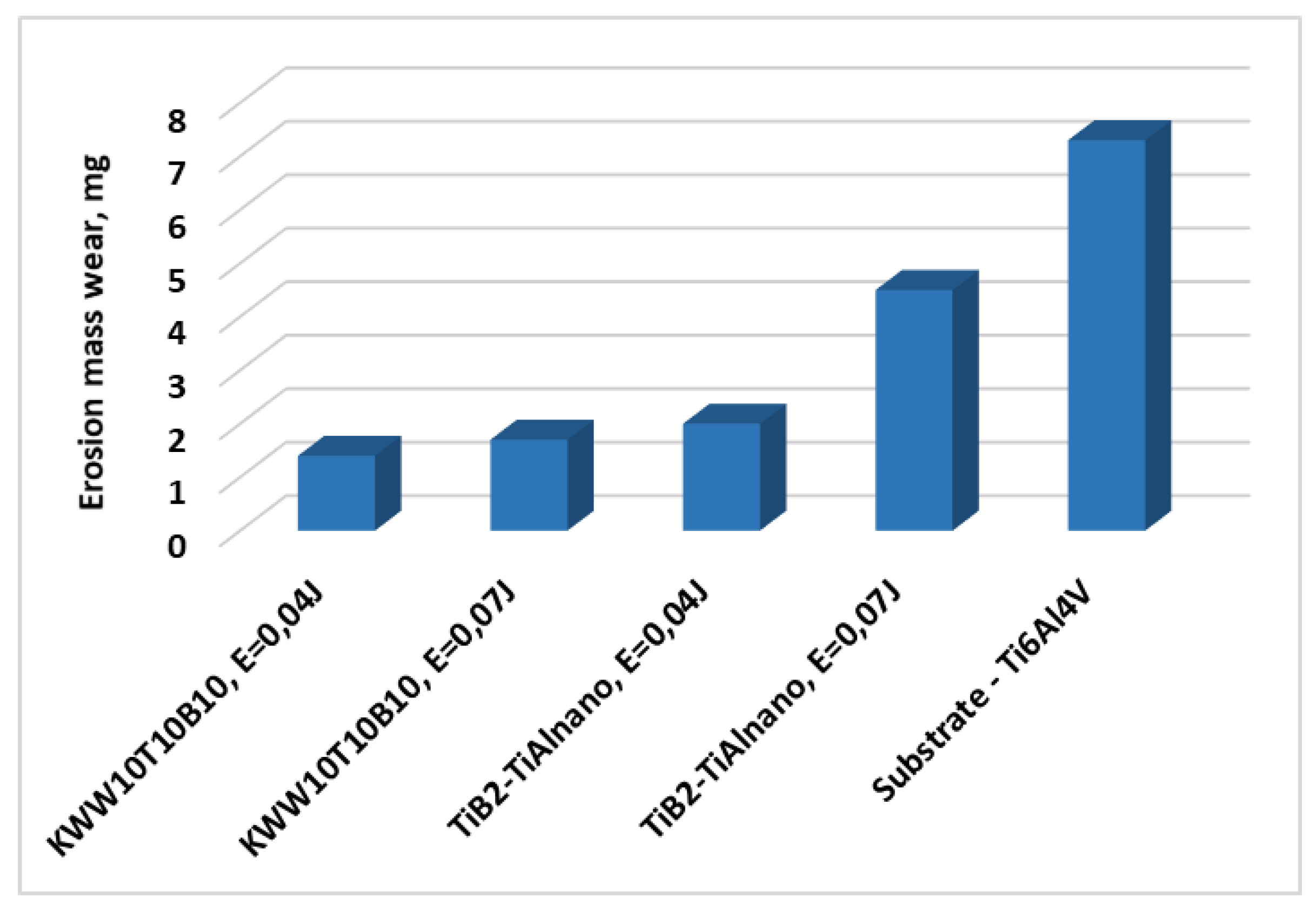
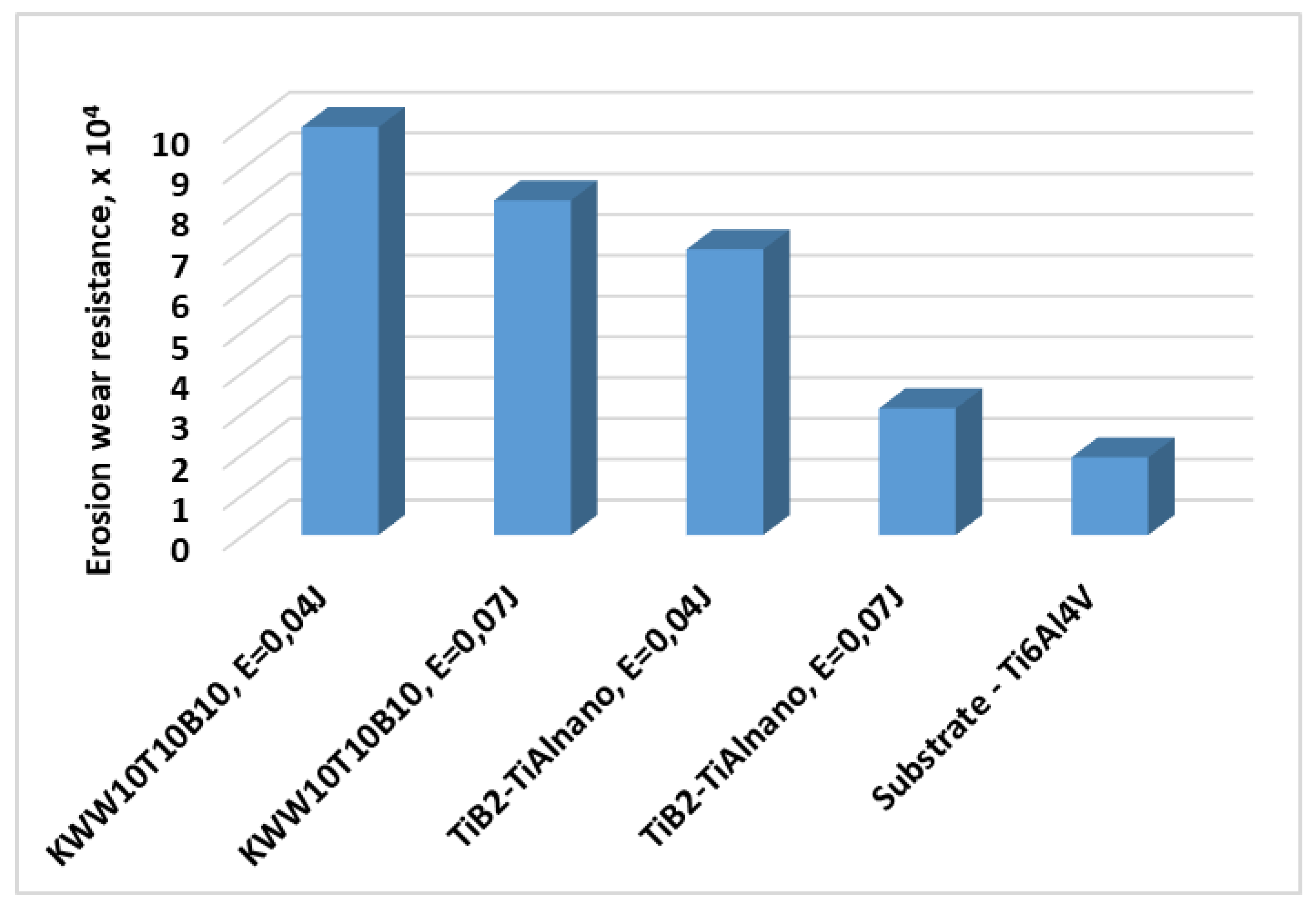
  • Coatings deposited with both types of electrodes at pulse energy 0.04 J were found to have up to four times higher abrasive wear resistance than that of uncoated titanium surfaces. The erosion wear resistance of KW10B10T10 electrode coatings at pulse energy up to 0.04 J is up to five times higher than that of uncoated titanium surfaces and 40% higher than that of TiB2–TiAlnano electrode coatings.
  • Coatings deposited at pulse energy up to 0.04 J from both types of electrodes are suitable for operation in dry abrasive friction conditions. KW10T10B10 electrode coatings are more suitable than TiB2–TiAlnano electrode coatings under erosive wear conditions with an interaction angle of 90°.

Author Contributions

Conceptualization, T.P. and G.K.; Methodology, T.P. and G.K.; Validation, V.K. and M.K.; Formal analysis, V.K. and R.D.; Experiments, V.K., A.N., M.K. and R.D.; Data curation, T.P. and G.K.; Writing—original draft preparation, T.P. and G.K.; Writing, T.P. and G.K.; Editing and translation, V.K. and R.D.; Visualization, T.P. and G.K.; Project administration, V.K. All authors have read and agreed to the published version of the manuscript.

Funding

This research was funded by the Bulgarian National Science Fund of the Ministry of Education and Science under the project No: KP-06-H37/19 “Technological features and regularities of creation of new high wear resistant composite coatings on titanium alloys by electrical spark deposition process”.

Institutional Review Board Statement

Not applicable.

Informed Consent Statement

Not applicable.

Data Availability Statement

Not applicable.

Conflicts of Interest

The authors declare no conflict of interest.

References

  1. Williams, J.C. Alternate materials choices—Some challenges to the increased use of titanium alloys. Mater. Sci. Eng. A 1999, 263, 107–111. [Google Scholar] [CrossRef]
  2. Dong, H. Tribological properties of titanium-based alloys. In Surface Engineering of Light Alloys; Series in Metals and Surface Engineering Cambridge; Woodhead Publishing: Sawston, UK, 2010; pp. 58–80. [Google Scholar]
  3. Garbacz, H.; Wiecinski, P.; Ossowski, M.; Ortore, G.; Wierzcho, T.; Kurzydłowski, K.J. Surface engineering techniques used for improving the mechanical and tribological properties of the Ti6A14V alloy. Surf. Coat. Technol. 2008, 202, 2453–2457. [Google Scholar] [CrossRef]
  4. Penyashki, T.; Kamburov, V.; Kostadinov, G.; Kandeva, M.; Dimitrova, R.; Nikolov, A. Some ways to increase the wear resistance of titanium alloys. J. Balk. Tribol. Assoc. 2021, 27, 1–20. [Google Scholar]
  5. Martini, C.; Ceschini, L. A comparative study of the tribological behaviour of PVD coatings on the Ti–6Al–4V alloy. Tribol. Int. 2011, 44, 297–308. [Google Scholar] [CrossRef]
  6. Anand, A.; Das, M.; Kundu, B.; Balla, V.K.; Bodhak, S.; Gangadharan, S. Plasma-sprayed Ti6Al4V alloy composite coatings reinforced with in situ formed TiB-TiN. J. Therm. Spray Technol. 2017, 26, 2013–2019. [Google Scholar] [CrossRef]
  7. Grabarczyk, J.; Batory, D.; Kaczorowski, W.; Niedzielski, P. Comparison of Different Thermo-Chemical Treatments Methods of Ti-6Al-4V Alloy in Terms of Tribological and Corrosion Properties. Materials 2020, 13, 5192. [Google Scholar] [CrossRef]
  8. Lisiecki, A.; Piwnik, J. Tribological characteristic of titanium alloy surface layers produced by diode laser gas nitriding. Arch. Metall. Mater. 2016, 61, 543–552. [Google Scholar] [CrossRef]
  9. Pohrelyuk, I.M.; Padgurskas, J.; Tkachuk, O.; Luk’yanenko, A.G.; Trush, V.S.; Lavrys, S.M. Influence of Oxynitriding on Antifriction Properties of BT6 Titanium Alloy. J. Frict. Wear 2020, 41, 457–463. [Google Scholar] [CrossRef]
  10. Zhang, Y.; Li, L.; Chang, Q. Research status and prospect of electro-spark deposition technology. Surf. Technol. 2021, 50, 150–161. [Google Scholar]
  11. Penyashki, T.; Kostadinov, G.; Kandeva, M.; Radev, D. Electro Spark and Gas Flame Layering Opportunities and Application; Roll Company Publishing House: Sofia, Bulgaria, 2020; p. 198. (In Bulgarian) [Google Scholar]
  12. Johnson, R.N.; Sheldon, G.L. Advances in the electrospark deposition coating process. J. Vac. Sci. Technol. A 1986, 4, 2740–2746. [Google Scholar] [CrossRef]
  13. Mikhailov, V.V.; Gitlevich, A.E.; Verkhoturov, A.D.; Mikhaylyuk, A.; Belyakovsky, A.V.; Konevtsov, L.A. Electrospark alloying of titanium and its alloys, physical and technological aspects and the possibility of practical use. Short review. Part I. Features of mass transfer, structural and phase transformations in surface layers, their wear and heat resistance. Electron. Mater. Process. 2013, 49, 21–44. [Google Scholar]
  14. Mikhailov, V.V.; Pasinkovsky, E.A.; Bachu, K.A.; Peretyatku, P.V. On the issue of electrospark alloying of titanium and its alloys. Surf. Eng. Appl. Electrochem. 2006, 3, 106–111. [Google Scholar]
  15. Wang, R.J.; Qian, Y.Y.; Liu, J. Structural and Interfacial Analysis of WC92-Co8 Coating Deposited on Titanium Alloy by Electrospark Deposition. Appl. Surf. Sci. 2004, 228, 405–409. [Google Scholar] [CrossRef]
  16. Levashov, E.A.; Zamulaeva, E.I.; Kudryashov, A.E.; Vakaev, P.V.; Petrzhik, M.I.; Sanz, A. Materials science and technological aspects of electrospark deposition of nanostructured WC-Co coatings onto titanium substrates. Plasma Process. Polym. 2007, 4, 293–300. [Google Scholar] [CrossRef]
  17. He, P.; Qian, Y.; Chang, Z.L.; Wang, R.J. Adhesion Behavior of WC Coating Deposited on Titanium Alloy by Electrospark Deposition. Solide State Phenom. 2007, 127, 325–330. [Google Scholar] [CrossRef]
  18. Paustovsky, A.V.; Tkachenko, Y.G.; Alfintseva, R.A.; Kirilenko, S.N.; Yurchenko, D.Z. Optimization of the composition, structure and properties of electrode materials and electrospark coatings during the strengthening and restoration of metal surfaces. Electron. Mater. Process. 2013, 49, 4–13. [Google Scholar]
  19. Kudryashov, A.E.; Eremeeva, Z.V.; Levashov, E.A.; Lopatin, V.Y.; Sevostyanova, A.V.; Zamulaeva, E.I. On Application of Carbon-Containing Electrode Materials in Technology of Electrospark Alloying: Part 1. Peculiarities of Coating Formation Using Electrospark Treatment of Titanium Alloy OT4-1. Surf. Eng. Appl. Electrochem. 2018, 54, 437–445. [Google Scholar] [CrossRef]
  20. Nikolenko, V.; Verkhoturov, A.D.; Syui, N.A. Generation and study of new electrode materials with self-fluxing additives to improve the efficiency of mechanical electrospark alloying. Surf. Eng. Appl. Electrochem. 2015, 51, 38–45. [Google Scholar] [CrossRef]
  21. Kandeva, M.; Penyashki, T.; Kostadinov, G.; Nikolova, M.; Grozdanova, T. Wear resistance of multi-component composite coatings applied by concentrating energy flows. In Proceedings of the Engineering Sciences-PES journal-16th International Conference on Tribology, Kragujevac, Serbia, 15–17 May 2019; Volume 1, pp. 197–207. [Google Scholar]
  22. Rukanskis, M.; Padgurskas, J.; Sabalius, A.; Michailov, V.; Kazak, N.; Zunda, A. Friction and Wear of Electrospark Coatings Made of Molybdenum, Bronze, and Combined (Ti+Al+C) Composition on Steel 45 in a Lubricant Medium. J. Frict. Wear 2021, 42, 56–62. [Google Scholar] [CrossRef]
  23. Kováčik, J.; Baksa, P.; Emmer, Š. Electro spark deposition of TiB2 layers on Ti6Al4V alloy. Acta Metall. Slovaca 2016, 22, 52–59. [Google Scholar] [CrossRef]
  24. Penyashki, T.; Radev, D.; Kandeva, M.; Kostadinov, G. Structural and tribological properties of wear resistant coatings obtained by electrospark deposition. In IOP Conference Series: Materials Science and Engineering; IOP Publishing: Bristol, UK, 2020; pp. 1–10. [Google Scholar]
  25. Penyashki, T.; Radev, D.; Kandeva, M.; Kostadinov, G. Structural and Tribological Properties of Multicomponent Coatings on 45 and 210Cr12 Steels Obtained by Electrospark Deposition with WC-B4C-TiB2-Ni-Cr-Co-B-Si Electrodes. Surf. Eng. Appl. Electrochem. 2019, 55, 638–650. [Google Scholar] [CrossRef]
  26. Penyashki, T.; Kostadinov, G.; Radev, D. Comparative studies of the tribological characteristics of carbon steels with gas flame coatings from new multi-component carbide composite materials. Oxid. Commun. 2019, 42, 74–89. [Google Scholar]
  27. Levashov, E.A.; Vakaev, P.V.; Zamulaeva, E.I.; Kudryashov, A.E.; Pogozhev, Y.S.; Shtansky, D.V.; Voevodin, A.A.; Sanz, Z. Nanoparticle dispersion-strengthened coatings and electrode materials for electrospark deposition. Thin Solid Film. 2006, 515, 1161–1165. [Google Scholar] [CrossRef]
  28. Levashov, E.A.; Kudryashov, A.E.; Pogozhev, Y.S.; Vakaev, P.V.; Zamulaeva, E.I.; Sviridova, T.A. Specific Features of Formation of Nanostructured Electrospark Protective Coatings on the OT4-1 Titanium Alloy with the Use of Electrode Materials of the TiC–Ti3AlC2 System Disperse Strengthened by Nanoparticles. Russ. J. Non-Ferr. Met. 2007, 48, 362–372. [Google Scholar] [CrossRef]
  29. Kandeva, M.; Penyashki, T.; Kostadinov, G.; Kalichin, Z. Abrasive and Erosion Wear of Composite NiCrSiB Coatings Inflicted with Subsonic Flammable Structure through a Cold Process. In IOP Conference Series: Materials Science and Engineering; IOP Publishing: Bristol, UK, 2020; Volume 724, p. 0120149. [Google Scholar]
Figure 1. Topography of the coated titanium surfaces at pulse energy 0.07 J. (a) Coating from KW10T10B10 electrode; (b) Coating from TiB2–TiAlnano electrode.
Coatings 13 00215 g001
Figure 2. The SEM topography of ESD coated titanium (Ti6Al4V) surface with different electrodes. (a) ESD with KW10T10B10 electrode, E = 0.07 J; (b) ESD with TiB2–TiAlnano electrode, E = 0.07 J; (c) ESD with KW10T10B10 electrode, E = 0.04 J; (d) ESD with TiB2–TiAlnano electrode, E = 0.04 J.
Coatings 13 00215 g002
Figure 3. Cross-section microphotographs of coatings, E = 0.04 J. (a) KW10T10B10; (b) TiB2–TiAlnano.
Coatings 13 00215 g003
Figure 4. XRD diffraction patterns of coatings from ”KW” and TiB2–TiAlnano electrodes on Ti-GR2, E = 0.04 J. (a) coating from KW10T10B10 electrode; (b) coating from TiB2–TiAlnano electrode.
Coatings 13 00215 g004
Figure 5. The scratch track, the coefficient of friction (μ), tangential force (Ft) of coatings from KW10T10B10 and TiB2–TiAlnano electrode, E = 0.07 J. (a) The scratch track of KW10T10B10 coating; (b) The scratch track of TiB2–TiAl coating; (c) Coating from KW10T10B10 electrode; (d) Coating from TiB2-Tilnaoo coating.
Coatings 13 00215 g005
Figure 6. Mass loss of the tested coatings (abrasive wear).
Coatings 13 00215 g006
Figure 7. Wear resistance of the tested coatings (abrasive wear).
Coatings 13 00215 g007
Figure 8. Mass loss of the tested coatings (erosive wear).
Coatings 13 00215 g008
Figure 9. Wear resistance of the tested coatings (erosive wear).
Coatings 13 00215 g009
Table 1. Roughness Ra, Rz, Rq, Rt, thickness δ and microhardness HV of coatings on Ti6Al4V substrates.
Coating ElectrodeRa, µmRz, µmRq, µmRt, µmδ, µmHV, GPa
0substrate Ti6Al4V2.26.262.137.1-3.75
1KW10T10B10, E = 0.04 J3.449.83.7910.8813.8511.85
2KW10T10B10, E = 0.07 J4.2511.954.3512.0516.8713.74
3TiB2–TiAlnano, E = 0.02 J2.296.472.36.547.779.67
4TiB2–TiAlnano, E = 0.04 J2.647.572.737.649.6311.53
5TiB2–TiAlnano, E = 0.07 J3.5610.433.8810.8412.8712.46
Table 2. Crystallite sizes of the main phases in the ESD coatings at pulse energy 0.03 J.
Phase/
Electrode
Crystal Lattice Parameters, A0Coatings from Electrode KW10T10B10Coatings from Electrode TiB2–TiAlnano
Average Crystallite Size, nm
α-Tia = 2.946 Å, c = 4.686 Å3236
TiN0.3a = 2.956 Å, c = 4.77 Å4333
TiN4.214 Å25-
TiC1-x4.38 Å10-
TiCxNy4.30–4.26 Å14traces
TiB-4235
TiB2a = 2.96 Å, c = 3.31 Å2821
TiAl33.976 Å3426
Al2O37.955 Å4754
TiO2,TiO tracestraces
WC1-x4.229 Å15-
Ti5Si3a = 7.445 Å, c = 5.153 Å12-
AlSi3Ti2a = 3.612 Å, b = 13.712 Å, c = 3.456 Å13-
Al0.9Ni1.12.8716 Å63-
Disclaimer/Publisher’s Note: The statements, opinions and data contained in all publications are solely those of the individual author(s) and contributor(s) and not of MDPI and/or the editor(s). MDPI and/or the editor(s) disclaim responsibility for any injury to people or property resulting from any ideas, methods, instructions or products referred to in the content.

