1. Introduction
It is well known that biological fouling (or biofouling) is a major concern, especially for the maritime industry. Indeed, biofouling organisms, ranging from bacteria to barnacles, cause numerous technical problems and incurs a heavy economic penalty [
1]. Therefore, a variety of methods have been investigated. The use of antifouling coatings is the most common means for the inhibition of micro- and macro-fouling.
However, most of these traditional coating solutions use organic biocides and toxic coatings, that may accumulate in the marine environment [
2]. Due to the risk of leaching into the aquatic environment and toxicity to aquatic organisms, “green” alternatives to toxic-based technologies are therefore required.
Several works highlight different materials to prevent this biofouling effect. Recently, zinc oxide (ZnO) has been widely reported as promising material for preventing the undesirable growth of micro- and macro-organisms [
1]. This material has several advantages such as chemical stability and biocompatibility [
3].
It is environmentally friendly, inexpensive, and easy to synthesize [
4]. In addition, it is a well-known photocatalyst [
5] that displays antibacterial [
6] and antifouling properties [
7]. Moreover, this material is a good candidate for oil-water separation [
8].
This metal oxide can exist in different forms and shapes, such as in zero dimensional 0D (nanoparticles) [
4], one dimensional 1D (nanorods) [
9], two dimensional 2D (thin films) [
10], or three dimensional 3D (nanoflowers [
11], nanosheets [
12], nanowalls [
13], nanoflakes [
14]).
Among these nanostructures, zinc oxide nanorods (ZnO NRs) have received widespread attention. These 1D nanostructures have highly active surfaces and large surface-to-volume ratios [
15], fewer grain boundaries and defects, and efficient charge transport along the nanorods axis. They also exhibit multiple semiconductor, piezoelectric and pyroelectric properties [
16]. Furthermore, ZnO NRs gained considerable interest for marine antifouling applications due to their antibacterial and antifouling activities [
7].
In the literature, Priyanka Sathe et al. successfully developed sunlight-responsive antifouling ZnO nanorods coated fishing nets that reduce the abundance of microfouling organisms by three-fold compared to uncoated nets (control) and nets painted with commercial biocidal coatings [
17]. Jiyeon Lee et al. [
18] reported that ZnO NRs are potentially useful as an adhesion resistant biomaterial. They showed that the cells adhered much more to a flat substrate than to the ZnO NRs.
Moreover, Al-Fori et al. [
19] showed that coatings containing ZnO NRs prevented marine micro and macrofouling in static conditions. They have reported that the anti-fouling effect was attributed to the reactive oxygen species produced by photocatalysis in the presence of sunlight.
In addition, Dobretsov et al. [
20] performed toxicity assays on ZnO NRs and spherical ZnO nanoparticles (ZnO NPs). They showed that the lowest toxicity was for ZnO NRs whereas the highest toxicity was observed for ZnO NPs.
Due to their excellent properties, a wide range of techniques have been presented to synthesize zinc oxide nanostructures. ZnO NRs have been synthesized by many techniques, such as electro-chemical deposition [
21], chemical vapor deposition (CVD) [
22], vapor–liquid–solid (VLS) growth [
23], etc. However, these methods generally operate at high temperatures (>100 °C) and sophisticated equipment is required. The hydrothermal method was presented as an alternative to preparing ZnO nanorods.
This simple method presents an inexpensive low-temperature process (<100 °C) with scalability and high yield [
24].
The other advantage is that this method can be applied on different types of surfaces. Depending on the intended application, ZnO nanorods were synthesized on soft and hard substrates, such as polymer [
24], fabrics, cotton [
25], glass [
26], and metal [
27].
Several studies have reported the advantages of applying ZnO NRs to stainless steels in the field of medical, food processing, automotive, aviation, and other applications. This product displays a high resistance to corrosion and heat, high durability, high hardness, and fabrication flexibility [
28].
The purpose of the present research is to study the hydrothermal deposition of ZnO NRs on stainless steel. A static field immersion test was conducted in a tropical coastal marine environment in Singapore to evaluate the material for its ability to prevent biofouling settlement. To the best of our knowledge, there are few papers reporting the impact of the ZnO seed layer deposited on stainless steel on the formation of vertically aligned nanorods in antifouling applications.
2. Experimental
2.1. Materials
Ethanol, acetone, and methanol Sodium hydroxide (98%), Zinc acetate dihydrate (98%), zinc nitrate hexahydrate (98%), and hexamethylenetetramine (99%), were supplied by Alfa Aesar. Octadecyltrimethoxysilane (ODS) was purchased from Sigma Aldrich. All chemicals used were of analytical grade. In our experiments, we used distilled water to clean surfaces and to prepare solutions.
2.2. Experimental Setup
In this work, we used stainless steel 430 Martensitic SS (X12Cr16) with 0.12% Carbon and 16% Chromium as a substrate in our experiments. These substrates were cleaned in three different baths, namely acetone, ethanol, and water (5 min each in an ultrasonic bath), then dried with N
2 gas. In order to prepare ZnO seed layer and ZnO NRs, we relied on the work of Ali et al. [
27] with some changes in the synthesis protocol.
Figure 1 at the top of the dashed line shows the ZnO seed preparation protocol. Zinc acetate (91 mmol/L) and sodium hydroxide (67 mmol/L) were added separately in methanol (stirring for 15 min). Zinc acetate was used as a source of zinc while sodium hydroxide was used as a source of hydroxyl ions. The solutions were stirred until all of the solids dissolved to give transparent solutions. Then, sodium hydroxide (NaOH) was added drop by drop onto the zinc acetate (Zn(CH
3CO
2)
2·2H
2O) at 60 °C, with a frequency of 60 drops per minute. The obtained solution was stirred for 3 h at 20 °C to form a stable and clear solution, preventing the agglomeration of ZnO nanoparticles.
For the deposition of the above solution prepared solution on substrates, the chemical bath deposition (CBD) method was applied as it is a simple and low-cost approach. The stainless-steel pieces were immersed in the solution for 5 min, then dried at 110 °C for 10 min to remove the solvent and increase the adhesion between the film and the substrate. To ensure good uniformity and to avoid the formation of discontinuous film, this process was repeated three times.
Finally, the ZnO thin film was subjected to annealing at 250 °C for 15 min to obtain ZnO nanocrystals. In the literature, M. Andrés-Vergés et al. [
29] reported that the decomposition temperature of zinc acetate is 240 °C, allowing the formation of ZnO nanocrystals, which will subsequently serve as nucleation sites for the growth of ZnO NRs.
Figure 1 at the bottom of the dashed line illustrates the ZnO NRs synthesis process. These nanorods were grown hydrothermally using two precursors dissolved in water. Indeed, aqueous solutions of zinc nitrate and hexamethylenetetramine (HMTA) at an equimolar concentration of 0.025 M were mixed separately under stirring for 15 min.
At the end of the stirring, the two solutions were mixed and stirred for 5 min. Then, the stainless-steel substrates coated with ZnO nanocrystal seeds were deposited vertically in a support and placed in a Teflon reactor. Finally, the solution was slowly poured over the substrates and the closed reactor was transferred to the furnace. In this work, the duration of hydrothermal growth varied from 3 to 24 h. However, the oven temperature was kept constant at 90 °C. At the end of growth, the surfaces were removed, rinsed with water, then dried with nitrogen.
2.3. Field Immersion Test
A static field immersion test was carried out in a tropical coastal marine environment located in Singapore (1°17.6′ N, 103°45.7′ E). Immersion tests to investigate biofouling settlement were carried out based on the rapid field assessment tests as described in Lim et al. Three types of samples: (1) ZnO NRs grown on stainless steel for 24 h, (2) ZnO NRs grown on stainless steel for 24 h modified with ODS, and 3) untreated stainless steel (control), were tested. Three replicates for each type were prepared. Samples measuring 75 × 25 mm were randomly arranged in a block design on a precut slide box holder (Heathrow Scientific, Cat Ref HS15994A) that allows seawater flow-through (
Figure S7). Box holders were secured using zip-ties onto plastic PVC frames and immersed at a depth of 0.5 m below the surface.
Fouling settlement was first documented after two weeks. After examination, the samples were re-immersed and examined again at four weeks. During assessment, the holders were raised and rinsed in surrounding seawater to remove loosely attached detritus. The samples were photographed with a digital camera (Canon Powershot G16). Biofouling assessment was carried out following ASTM D6990-05
Standard Practice for Evaluating Biofouling Resistance and Physical Performance of Marine Coating Systems [
30]. The digital images of the surfaces were cropped to remove 10% area along the edge, to remove bias due to settlement on edge effects. Only visible macrofouling organisms in the central part of the coupons were enumerated.
All analyses were conducted in R v.3.6.1 [
31]. Data were examined if they fulfilled the assumptions of normality (Shapiro–Wilk normality test) and homogeneity of variance (Bartlett’s test). One-way ANOVA was used to analyze the means of total organisms against sample type.
2.4. Characterization
The crystalline structure of the substrates was characterized by X-ray diffraction (XRD) using a Siemens D5000 diffractometer. This device operates with Cu Kα radiation (λ = 1.5406 Å), an accelerating voltage of 40 kV, an applied current of 40 mA and 2θ from 20 to 60°. The morphology of the ZnO seeds and ZnO NRs was characterized using a scanning electron microscopy (FEG–SEM, NEON 40 ZEISS) operating at 5 kV accelerating voltage. In addition, an atomic force microscope AFM Dimension 3100 was used for surface analyses. Experiments were carried out at T = 4 K using a Joule-Thomson STM/AFM (SPECS, Berlin, Germany) with a base pressure of 10−10 mbar. High-resolution transmission electron microscopy (HRTEM, JEOL JEM-2100F) was used to observe the microstructures of ZnO nanowire that have been detached from the substrate and dispersed by sonication in isopropanol.
A droplet of the solution was dropped on a copper grid with carbon mesh. The drop shape analyzer (DSA25S, Kruss, Hamburg, Germany) was used to measure the water contact angles at room temperature. The deposited drop (droplet of distillate water with volume about ~5 μL) was observed using an integrated camera (TIS DFK 37BUX273, Bremen, Germany) to trace the surface line and the drop shape line. An average of three experiments at three positions on the surfaces was performed to calculate the final angles.
3. Results and Discussions
Several studies incorporate a nucleation layer under their ZnO nanorods. Therefore, deposition of a ZnO seed layer as a nucleation site to assist the growth, is very important to obtain well-oriented nanorods. In this section, we have studied the influence of different parameters on the seed layer, such as the deposition method, growth temperature, seed layer annealing temperature, and so on.
3.1. Effect of Seed Deposition Method on the Growth of ZnO NRs
To study the effect of the seed deposition method on the growth of ZnO nanorods, two deposition techniques were tested.
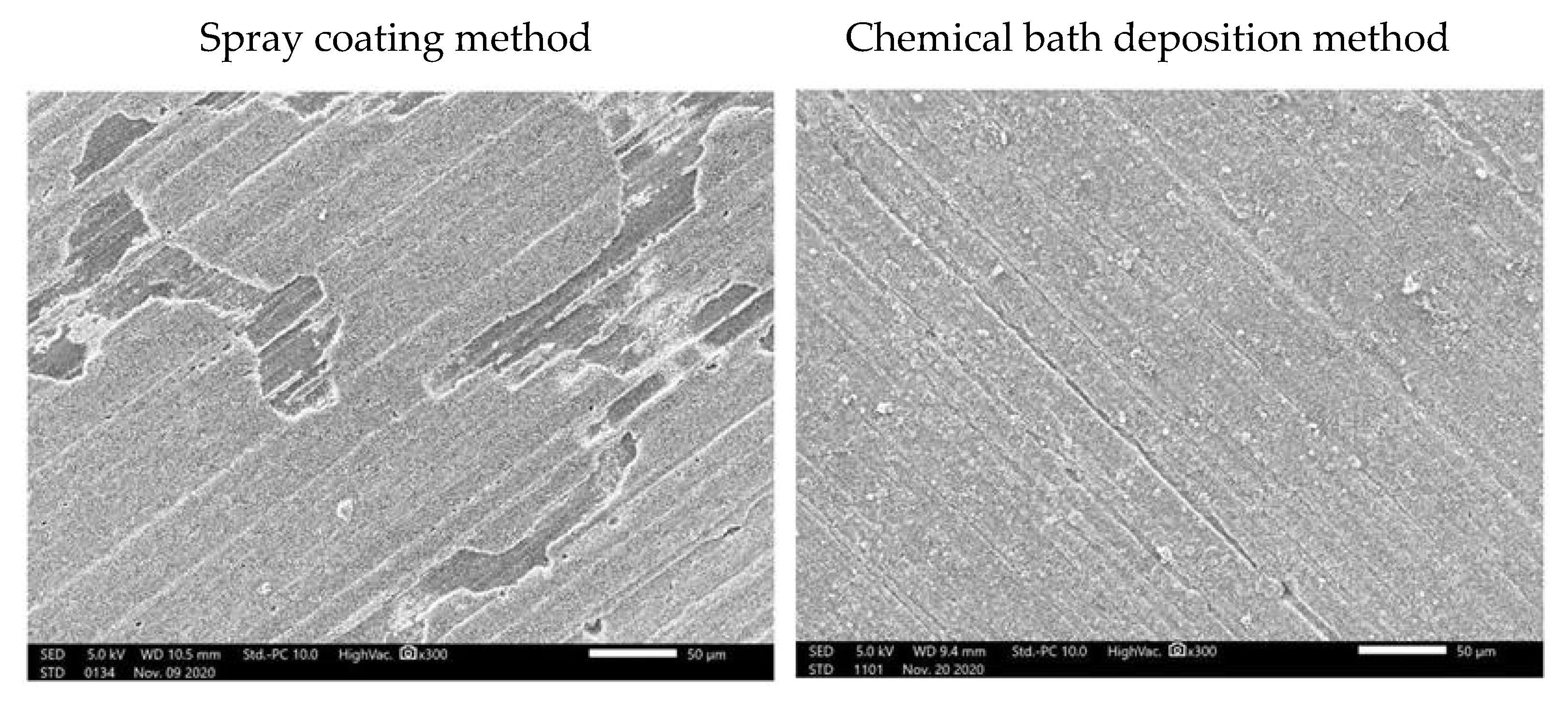
Figure 2 show SEM images at low magnification of the nanorods grown on a seed layer deposited by two different methods. The first one uses the spray coating technique to apply the seed solution on the stainless-steel substrate. After the growth of the nanorods on the seeded surface, we can clearly see from the image on the left that the growth was not homogeneous. However, the growth on the seeded surface deposited by chemical bath deposition presented homogeneous growth over the entire surface (image on the right). Therefore, for the rest of experiments, the seed layer was deposited using the chemical bath deposition technique.
3.2. Effect of Seed Layer Annealing Temperature
In order to study the effect of seed layer annealing temperature on the formation of ZnO nanorods, the growth was performed with and without annealing of the seed layer. Yang et al. [
32], have shown that zinc acetate begins to decompose into ZnO near 200 °C while the complete decomposition occurs before 300 °C. Moreover, Ohyama, M. et al. [
33] reported that the thermal decomposition temperature of zinc acetate is 240 °C. This study annealed the ZnO seed layer at 250 °C, which was sufficient to remove the solvent and organic substances produced by the decomposition and thus sufficient to allow crystallization of the film.
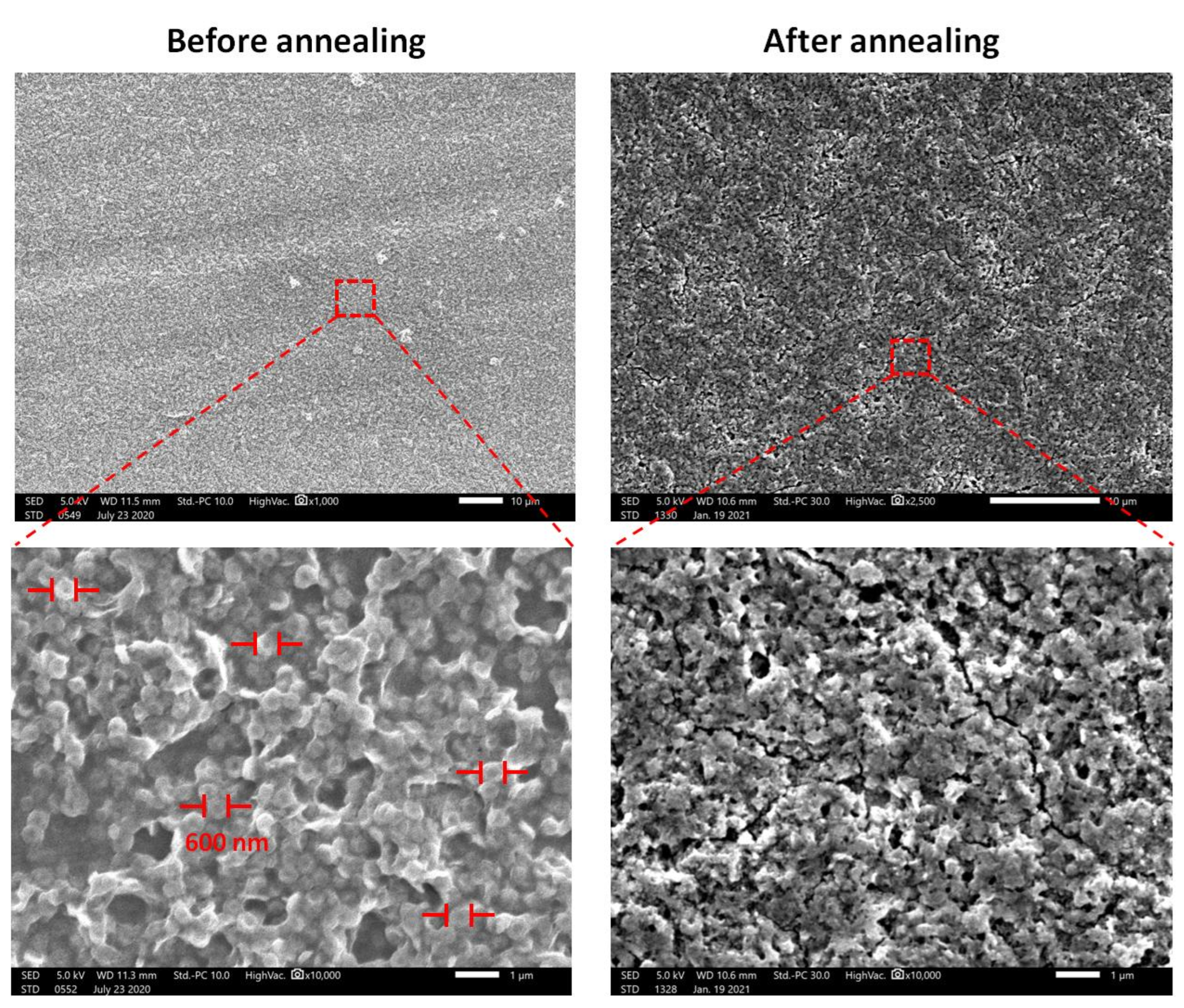
The morphology of the seeded layer before and after the thermal decomposition of zinc acetate is presented in the
Figure 3. It is clear from the SEM image on the left, corresponding to the seed layer before annealing, that the surface is formed by a ZnO nanodisk-like structure. The diameter of these nanodisks varied between 550 and 650 nm. It was observed that there is a porous structure with diameter of approximately 1 µm. However, the structure after annealing presented a different structure. As observed in the figure on the right, the nanodisk-like structure disappeared after annealing, revealing the appearance of seeds with diameters between 60 and 80 nm. In addition, the porosity on the surface has been reduced.
This result shows the importance of the annealing temperature to form ZnO nanoseeds rather than ZnO nanodisks. In the next section, we performed the growth of ZnO nanorods on seeded substrate before and after the annealing at 250 °C. This experiment will allow us to see the effect of annealing the seed layer before the growth on the formation of ZnO nanorods.
3.3. Effect of Annealing Temperature on the Seed Layer
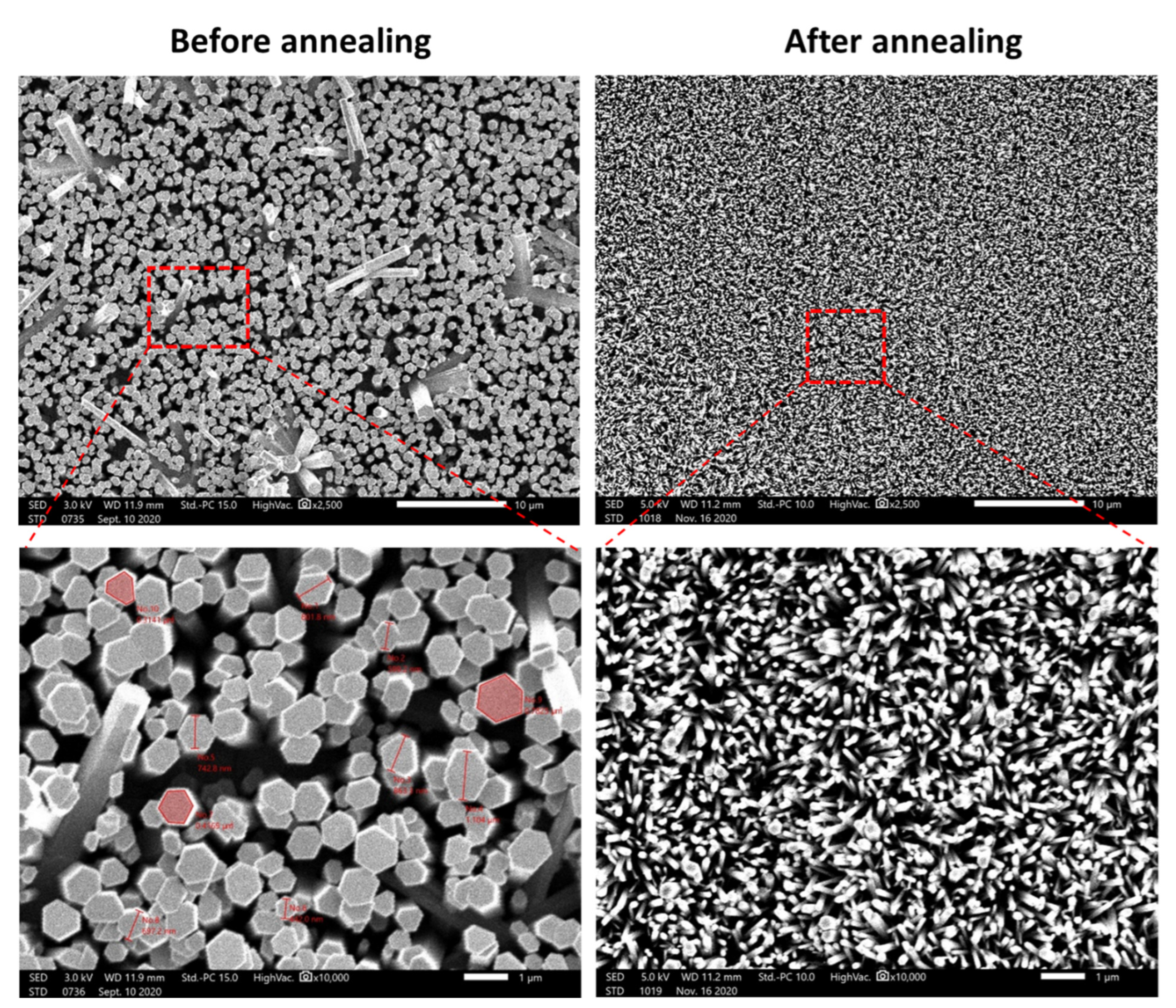
Figure 4 depicts the morphology of the annealed and non-annealed seed layer after 24 h of growth under hydrothermal conditions. We can clearly see that before the annealing, the diameters, density shapes, and length of the rods were different from those obtained after the annealing of the seed layer. It was found that the average diameter of nanorods strongly depends on the annealing temperature of the seed layer. For seed layer thickness of approximately 1000 nm, it was clearly observed that the ZnO diameter is 10 times lower (70 nm) than before annealing (700 nm).
Figure S1 shows a schematic corresponding to the growth mechanism on the seeded substrate before and after seed layer annealing temperature. This figure shows the effect of the annealing temperature to obtain either high-thickness and non-dense nanorods or fine and dense nanorods.
3.4. X-ray Diffraction Measurements (XRD)
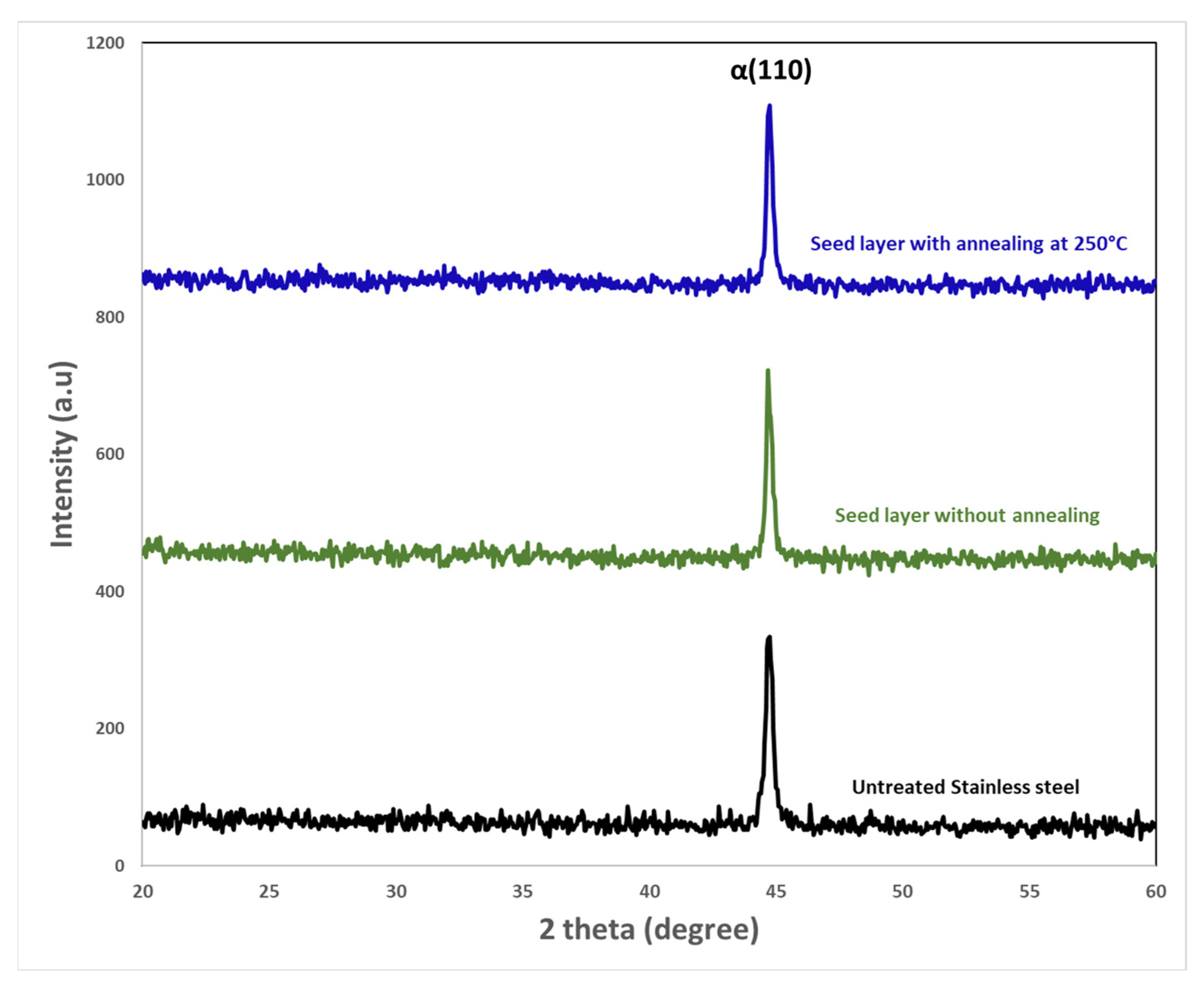
Figure 5 shows the X-ray diffraction patterns, before and after annealing at 250 °C, of untreated stainless steel and ZnO seeds deposited on this surface. We can see that no diffraction peak corresponding to zinc oxide was observed at any diffraction angle whether before annealing or after annealing at 250 °C. The XRD pattern exhibits only a strong diffraction at 2
θ = 44 − 44.5° which is coming from the substrate. This peak was ascribed to a single αFe (110) of the stainless steel 430 Martensitic SS (X12Cr16) [
34]. In the literature, there were similar observations. For example, Karim et al. [
35] did not show any intensity peak of ZnO on ZnO-coated SiO
2/Si substrate annealed at 350 °C for 30 min. Moreover, J. Bruncko et al. [
36] investigated the properties of amorphous undoped ZnO thin films prepared by pulsed laser deposition (PLD) under cryogenic conditions. They showed that the as deposited ZnO film on Silicon or Sapphire substrate exhibited an amorphous pattern. Therefore, after annealing at 200 °C, sapphire substrate had a more positive influence on ZnO recrystallization while ZnO deposited on silicon maintained the amorphous structure. In addition, Sea-Fue Wang et al. [
37] showed in their work that ZnO seed layers deposited on Si substrate using direct current reactive sputtering provides an amorphous-like film.
It is well known that the annealing temperature influenced the crystallographic properties of the ZnO seed layers. This study annealed the seed layer deposited on the substrate at 500 °C for 1 h in order to verify the existence of ZnO.
Figure S2 depicts the XRD patterns of untreated stainless steel and ZnO seed layer deposited on stainless steel substrate then annealed at 500 °C for 1 h. In
Figure S2, three weak peaks attributed to (100), (002), and (101) ZnO planes are observed. This result shows that the annealing allows the crystallization of the ZnO seeds.
3.5. Water Contact Angle (WCA)
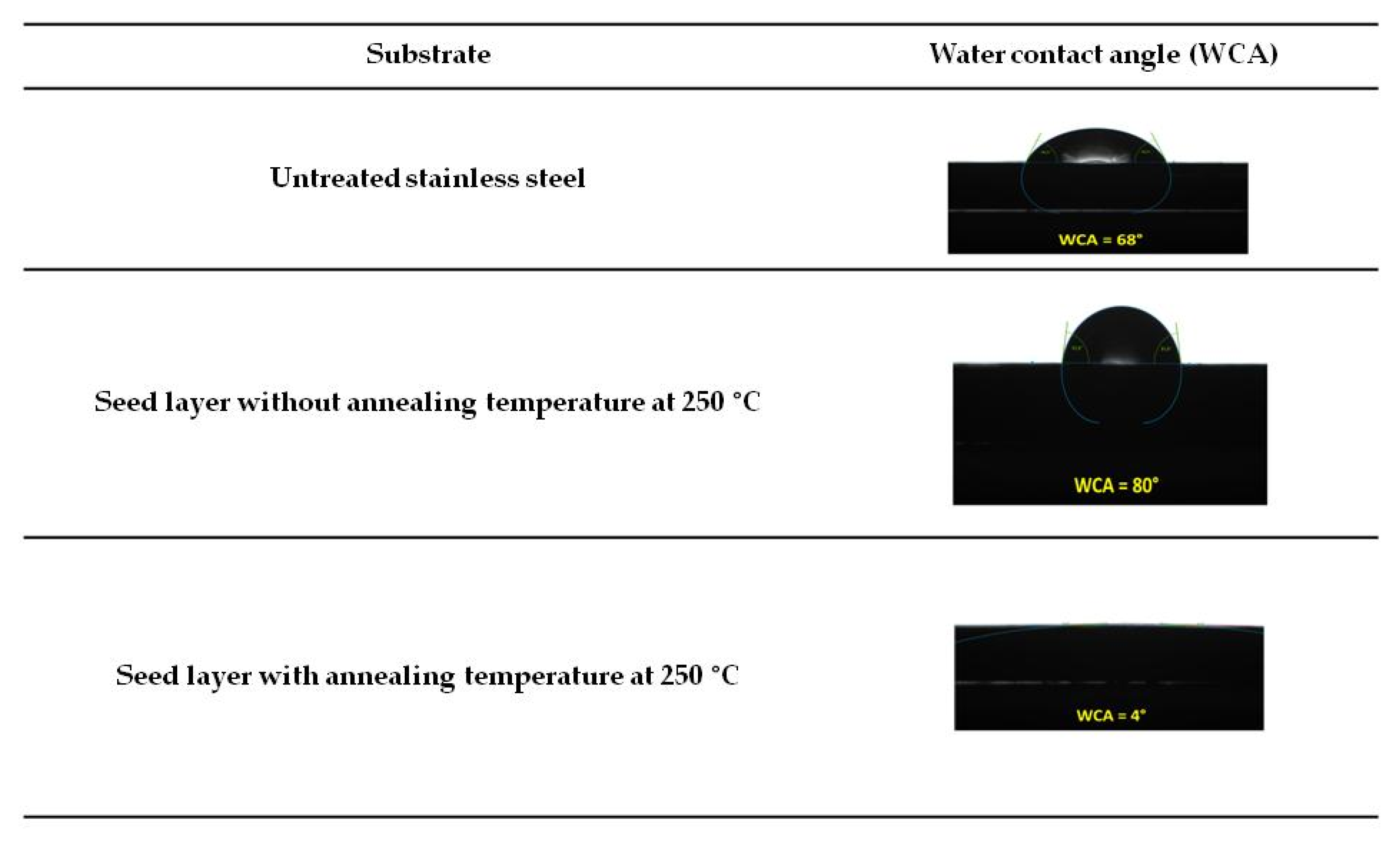
Surface wettability was examined by water contact angle measurement. The wetting behavior of the surfaces is shown in
Figure 6. The static contact angle of untreated stainless steel was found to be 68°. After depositing the seed layer without annealing at 250 °C, we notice the increase of the angle to 80°. As the surface of the seed layer has hydrophilic products such as Zn(OH)
2, it was expected to function as a hydrophilic surface. However, the surface presented pores, allowing the air to be trapped, and thus repelled water from the surface, which may explain the increase in the contact angle. In the literature, depending on the synthesis technique, deposition method, surface crystal structure, and surface roughness, authors have reported that the water contact angle of ZnO thin film can range from hydrophilic to hydrophobic [
38].
After annealing at 250 °C, it was found that the water contact angle decreased significantly to 4°, exhibiting a superhydrophilic behavior. This shows that the water droplets were absorbed and spread over the entire surface. It is well known that the hydrophilic properties can be improved by decreasing the surface roughness. In
Section 3.2, we showed that the roughness of the seed layer was decreased after annealing. Moreover, the obtained superhydrophilic surface could be attributed to the formation of oxygen vacancies on the surface of ZnO seed layer after annealing on air. These defect sites increase water adsorption on the surface [
39].
Figure S3 illustrates the average water contact angle on ZnO seed layer annealed in air at 500 °C. The measured contact angle was 0°. This superhydrophilic behavior is the same found for the annealing at 250 °C.
3.6. Effect of Growth Duration Time on the Formation of ZnO NRs
In this part, besides the growth time, the other parameters are kept constant in order to study the effect of the growth time on the morphology of the ZnO nanorods.
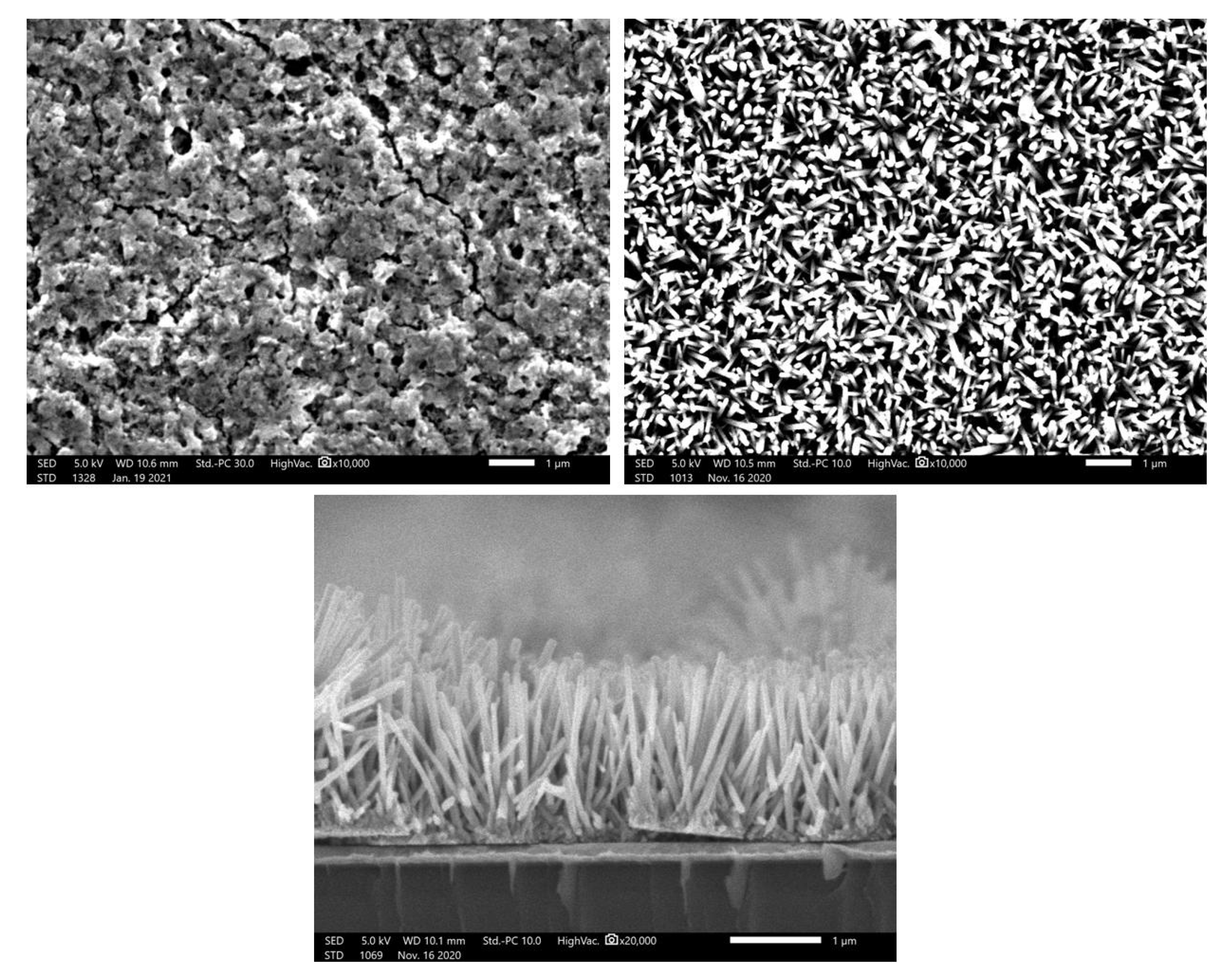
Figure 7 shows top-view SEM image of ZnO Seed layer and ZnO nanorods grown at 90 °C for 24 h on stainless steel substrate. It also shows the cross-sectional view of ZnO nanorods grown on silicon substrate for 24 h. The top-view SEM images of the different durations, 3 h, 6 h, and 12 h, are shown in
Figure S4.
Before the hydrothermal growth, we can clearly see that the seed layer displays a homogenous nanofilms with the presence of pores on the surface. After the hydrothermal growth, top view SEM images show that the nanorods were successfully grown homogeneously for the different duration times 3, 6, 12, and 24 h.
Figure 7 displays the top-view and cross-section view of the nanorods grown for 24 h.
As it was not possible to measure the length of the nanorods on stainless steel, ZnO seed layer was deposited on Au/Silicon as substrate which makes it easy to cleave the substrate and observe it in cross section.
Table 1 presents the average diameter and length of the samples grown at 90 °C for 3 h, 6 h, 12 h, and 24 h. It can be seen that the diameter size is almost constant for all the surfaces equal to ≈70 nm. The table also summarizes the average length of the nanorods. This shows that with the increase of the growth time, the length increases from 0.49 µm after 3 h of growth to 1.54 µm at 24 h of growth.
3.7. XRD Measurements as a Function of Growth Time
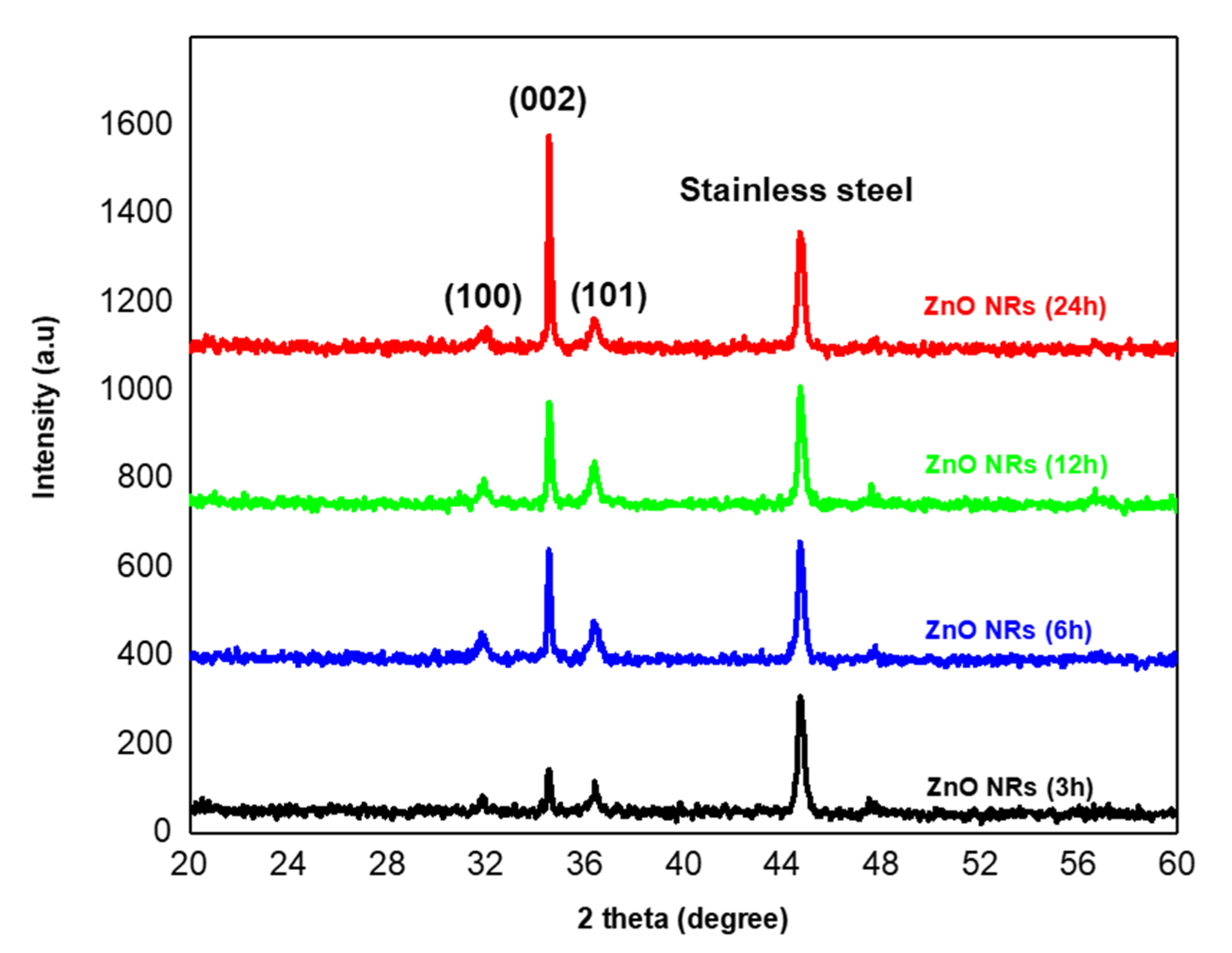
The crystallinity of ZnO nanorods was demonstrated using X-ray diffraction. The XRD pattern of ZnO NRs grown on seeded stainless steel at different durations is shown in
Figure 8. Unlike the X-ray diffraction of the seed layer (
Section 3.4), the XRD patterns show the appearance of a crystalline structure on the entire surface after 3 h, 6 h, 12 h, and 24 h of hydrothermal growth. Indeed, in addition to the peak coming from the substrate at 44.5° ascribed to the NiFe (111) plane, three other peaks were observed, a strong ZnO (002) diffraction peak at 2
θ = 34.8° and two weak diffraction peaks at 31.6 and 36.5°, corresponding to ZnO (100) and (101) planes respectively. As shown from SEM images, some nanorods were deposited randomly on the surface and others grown tilted, which could explain the polycrystalline structure of the sample. This result is consistent with the wurtzite structure of the grown ZnO nanorods (Joint Committee on Powder Diffraction Standards (JCPDS) Card No: 05-0664) [
40].
The dominant diffraction peak also reveals a preferential alignment of the nanorods in their c-axis orientation which is consistent with SEM observation. Moreover, the (002) peak was strong and narrow, demonstrating a high degree of crystallinity of the prepared nanorods. Additionally, there were no diffraction peaks of zinc or other impurities, which indicates the high purity of ZnO nanorods [
41].
As can be seen from the XRD data, the intensity of the peak (002) increases upon increasing the hydrothermal growth from 3 to 24 h. Apparently, the intensity of this dominant peak is proportional to the increase of the growth duration which signifies the enhanced crystalline quality. It is clearly observed that ZnO NRs grown after 24 h displays the highest intensity which demonstrates its high purity and crystallinity.
The calculated crystallite size and dislocation density of grown ZnO nanorods after 3 h, 6 h, 12 h, and 24 h are summarized in
Table 2.
The mean crystallite size,
D, was calculated according to the highest intensity peak, corresponding to the (002) diffraction plane using the Debye–Scherrer formula (Equation (1)) [
35]:
where
D = average crystallite size,
λ = X-ray wavelength
β = full width at half maximum (FWHM) of the 002 peak in radians, and
θ = Bragg angle.
According to the results shown in
Table 2, it can be seen that the calculated ZnO nanorods crystallite sizes were ranging from 30.5 nm until 52.68 nm. The
D value of grown ZnO nanorods after 12 h is the smallest compared to the other durations.
The dislocation density
δ was calculated from mean crystallite size
D using (Equation (2)) [
35], which is a measure of the number of dislocations in a unit volume of crystal.
Since the dislocation density is defined as the inverse square of the crystallite size, the δ value of grown ZnO nanorods after 12 h is the highest. This could be due to a large number of defects in the ZnO seed layer and hence in the ZnO nanorods.
3.8. Atomic Force Microscope (AFM) Measurements
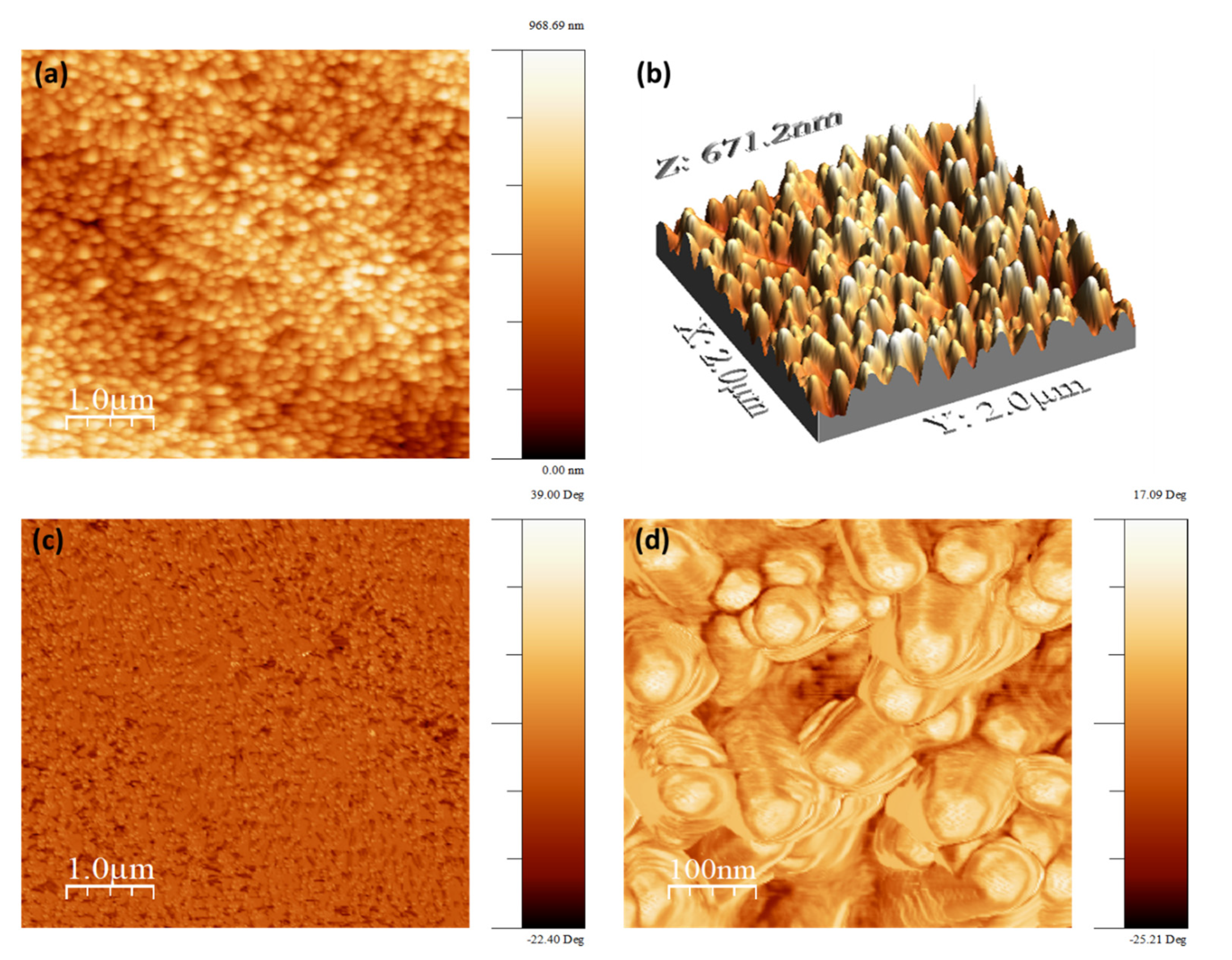
Figure 9 shows the topography and the phase of the ZnO nanorods surface grown on stainless steel substrate. It can be seen that the surface morphology of the nanorods is very dense, and ZnO NRs are vertical to the substrate. Here, the root mean square of the surface roughness is approximately 129 nm over an area of 5 µm × 5 μm. In addition, it can be seen, using the magnified AFM phase image, that the nanorods display hexagonal shape at the top end of ZnO. The AFM measurement confirms the SEM results obtained previously.
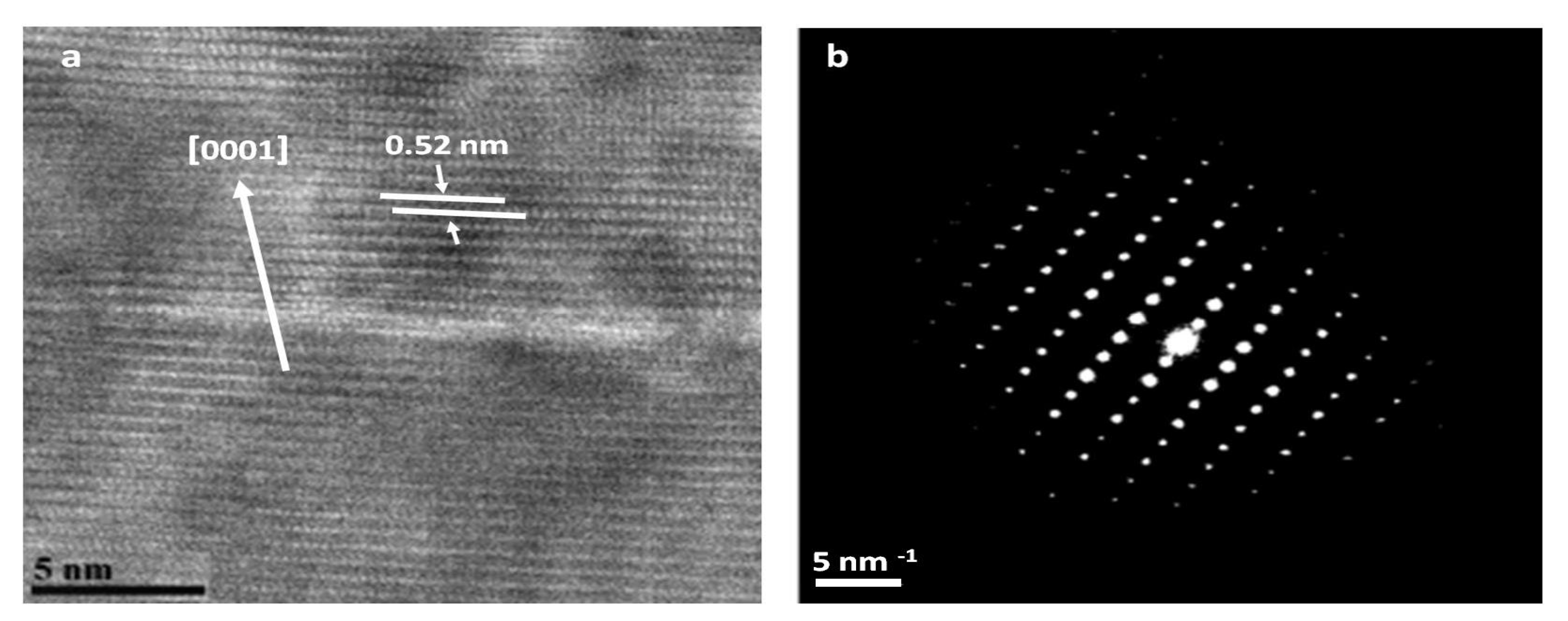
3.9. Transmission Electron Microscopy (TEM) Analysis
Figure 10 shows a HR-TEM image of ZnO nanowire after 24 h of hydrothermal growth on the left and selected area electron diffraction (SAED) pattern of the nanowire on the right. The crystallinity of ZnO nanowire was evidenced by high-resolution transmission electron microscopy and electron diffraction characterization.
From this figure, we can see that the d-spacing of the (0001) crystal planes is approximately 0.52 nm [
40]. This spacing shows that the ZnO nanorods have a perfect lattice structure and confirms that they grow along the c-axis. The selected area electron diffraction (SAED) analysis of the same nanowire is reported in
Figure 10 which shows the single crystalline nature of the material with (002) crystal planes along the growth direction.
3.10. Field Immersion Tests
It is well known that surface wettability plays an important role for biofouling prevention [
42]. Varied wettability ranging from superhydrophilic to superhydrophobic have been investigated. In this study, functionalized ZnO nanorods with ODS which is an alkyl silane was applied as a surface chemical modification [
43]. From
Figure S5, the sample before modification is superhydrophilic with WCA around 0°. After the chemical modification, the water contact angle increases from 0° to around 157°, making the surface superhydrophobic.
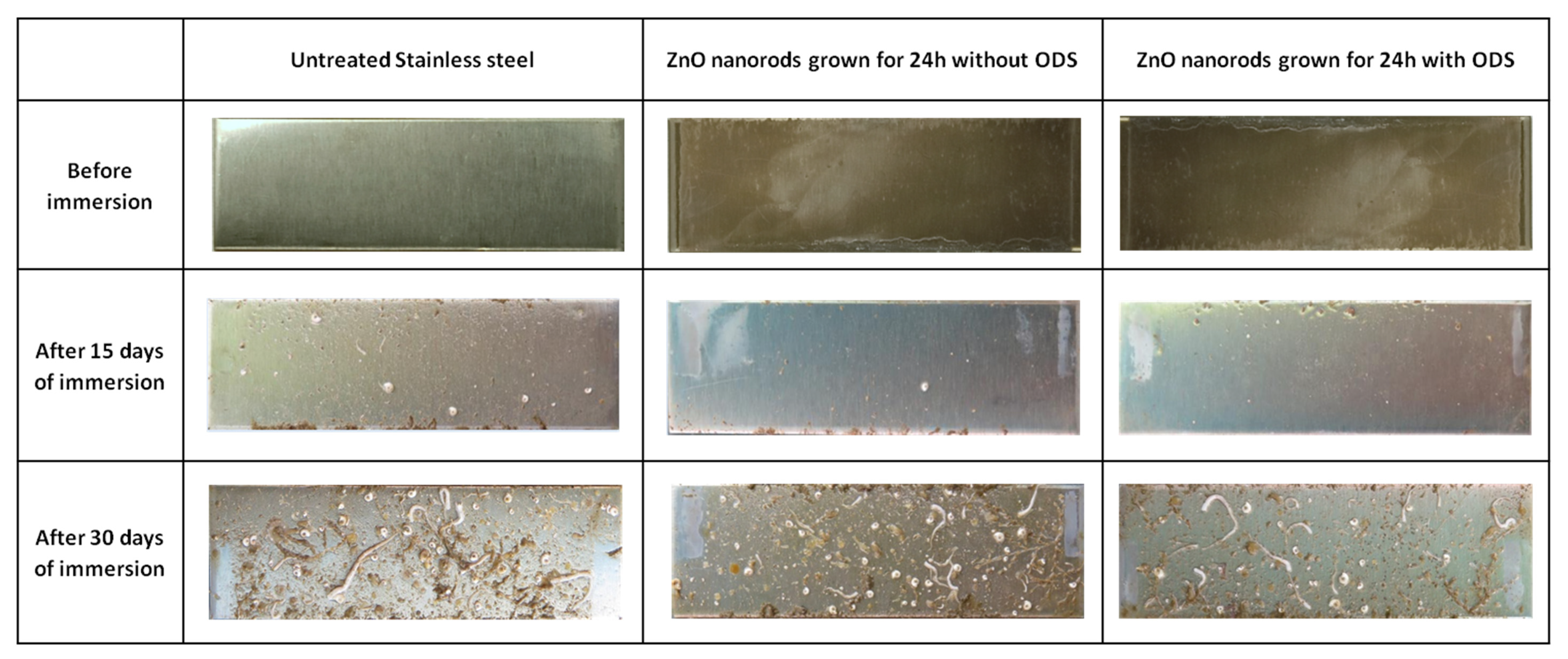
A field immersion test was conducted in a tropical coastal marine environment to investigate the surfaces immersed under natural seawater environment. Untreated stainless steel, ZnO nanorods grown for 24 h with and without ODS treatment were introduced into the sea water for different durations (
Figure 11).
Figure S6 shows the sample after one month of immersion in sea water, illustrating that the ZnO nanorods have not detached from the substrate, which confirms the good adhesion to the substrate.
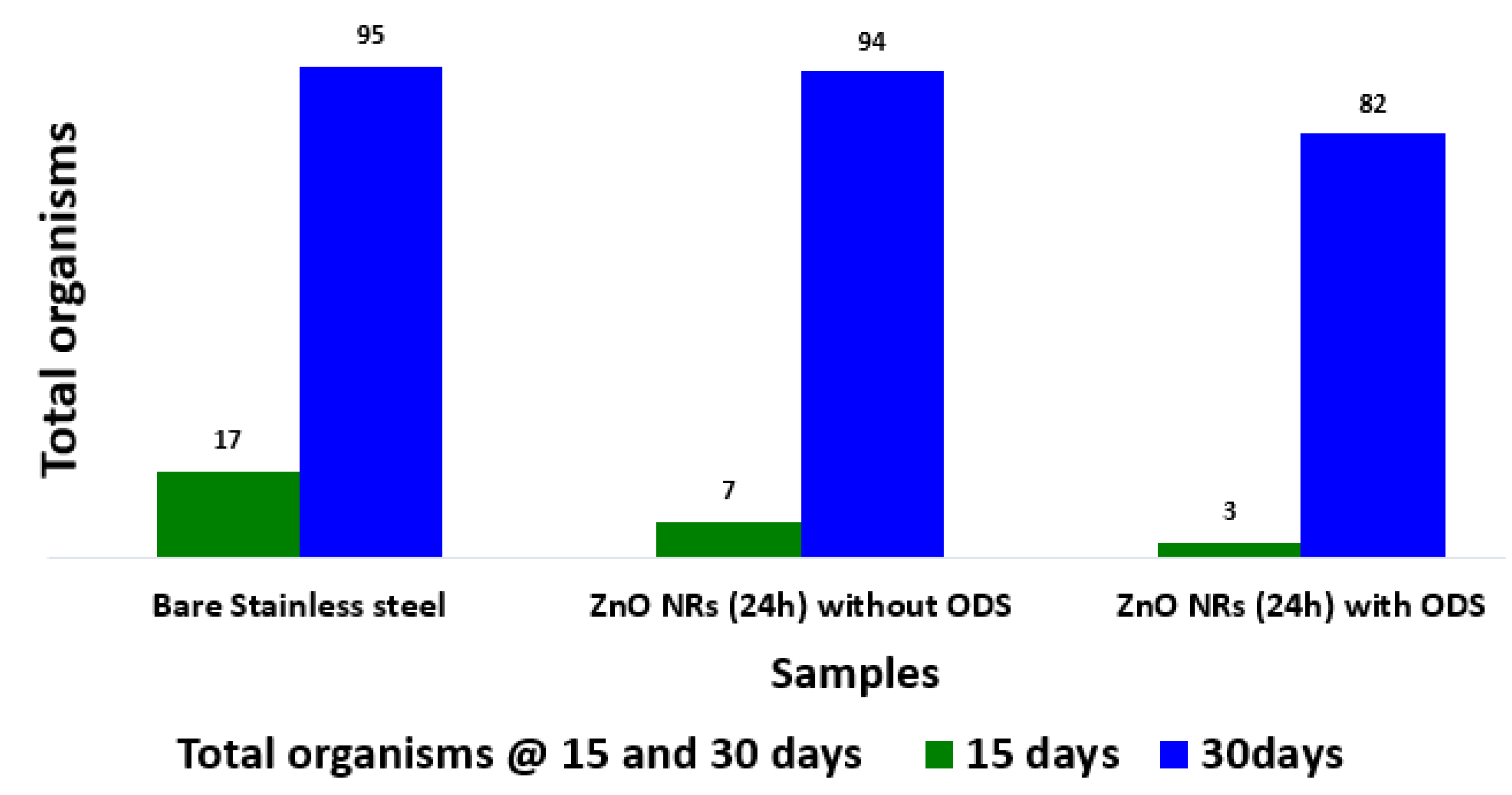
Figure 12 shows the total number of organisms on the surfaces after (1) 15 days, and (2) 30 days. The substrates with functionalized ZnO nanorods
with ODS generally had lower numbers of organisms on them compared to ZnO nanorods
without ODS and untreated stainless steel. However, the differences were not statistically significant after 30 days (F (2, 6) = 0.07,
p = 0.933). After 60 days of immersion, the entire substrate was stable against corrosion. This would be due to the steel itself, which has a protective layer, making it very resistant to corrosion and rust. The type of the organisms and their abundance on different substrates is summarized in
Supplementary Table S1. All the fouling settlements were counted, and thus the total number of organisms was analyzed.
4. Conclusions
To conclude, we successfully fabricated vertical aligned ZnO nanorods arrays (ZnO NRs) on conductive stainless-steel substrate using a low cost, low temperature, and eco-friendly hydrothermal approach. In this study, the effect of various parameters on the growth of dense and ZnO NRs has been investigated. We found that the annealing temperature influences the diameter of the ZnO seed layer and hence the diameter of the ZnO nanorods. Results also show that the diameter of the nanorods after annealing of the seed layer is 10 times lower (70 nm) than before annealing. We found that when the stainless-steel substrate was held vertically in the growth solution at 90 °C, only vertical aligned nanorods could be obtained, which avoids unwanted precipitation on the surface.
Moreover, ZnO nanorods were successfully grown homogeneously after 3, 6, 9, and 24 h and dense arrays of nanorods with uniform diameter were formed on all substrates. HR-TEM and XRD study confirmed the hexagonal wurtzite structure of ZnO nanorod arrays. The field immersion test indicates that the 1D nanomaterials functionalized with ODS attracted lower settlement of organisms, but the effect is not sustained. The future direction of this research activity is focusing on the replacement of the painting multilayered structure. We have investigated how a ZnO coating can be an alternative for sustainable development in the marine field. The main limitation is actually associated to the durability of the process.


 ,
, 


