
A Novel Low-Profile Self-Expanding Biodegradable Percutaneous Heart Valve Frame That Grows with a Child

 ,
,  ,
, 
Abstract
1. Introduction
2. Materials and Methods
2.1. Materials
2.2. Surface Treatments
2.2.1. Thermal Treatments
2.2.2. Ultra-Thin Polymer Coating
2.3. Degradation Test
2.4. Mechanical Testing
2.5. Computational Modeling
2.6. Prototype Fabrication
2.7. Biocompatibility Studies
3. Results
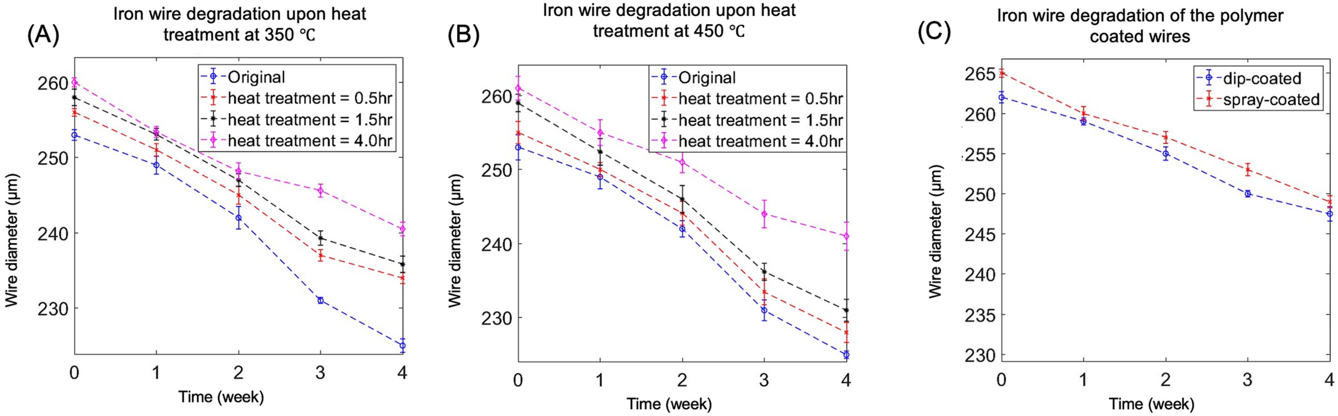
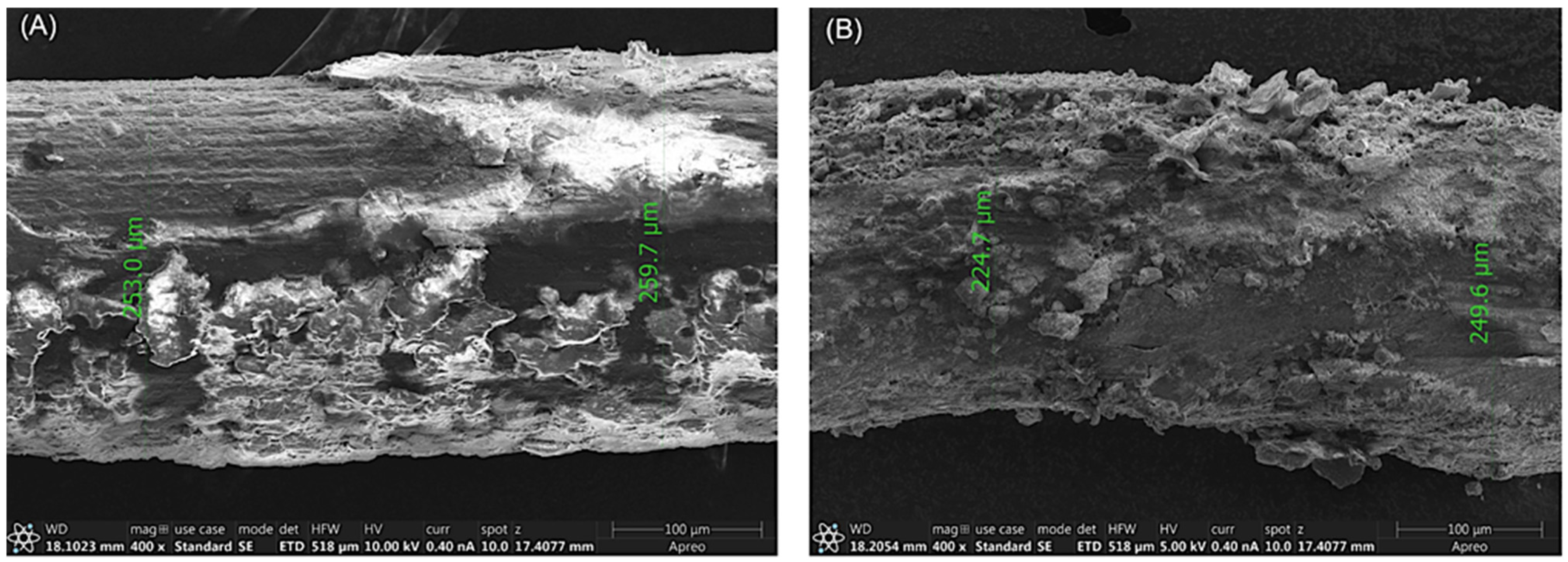
3.1. Degradation
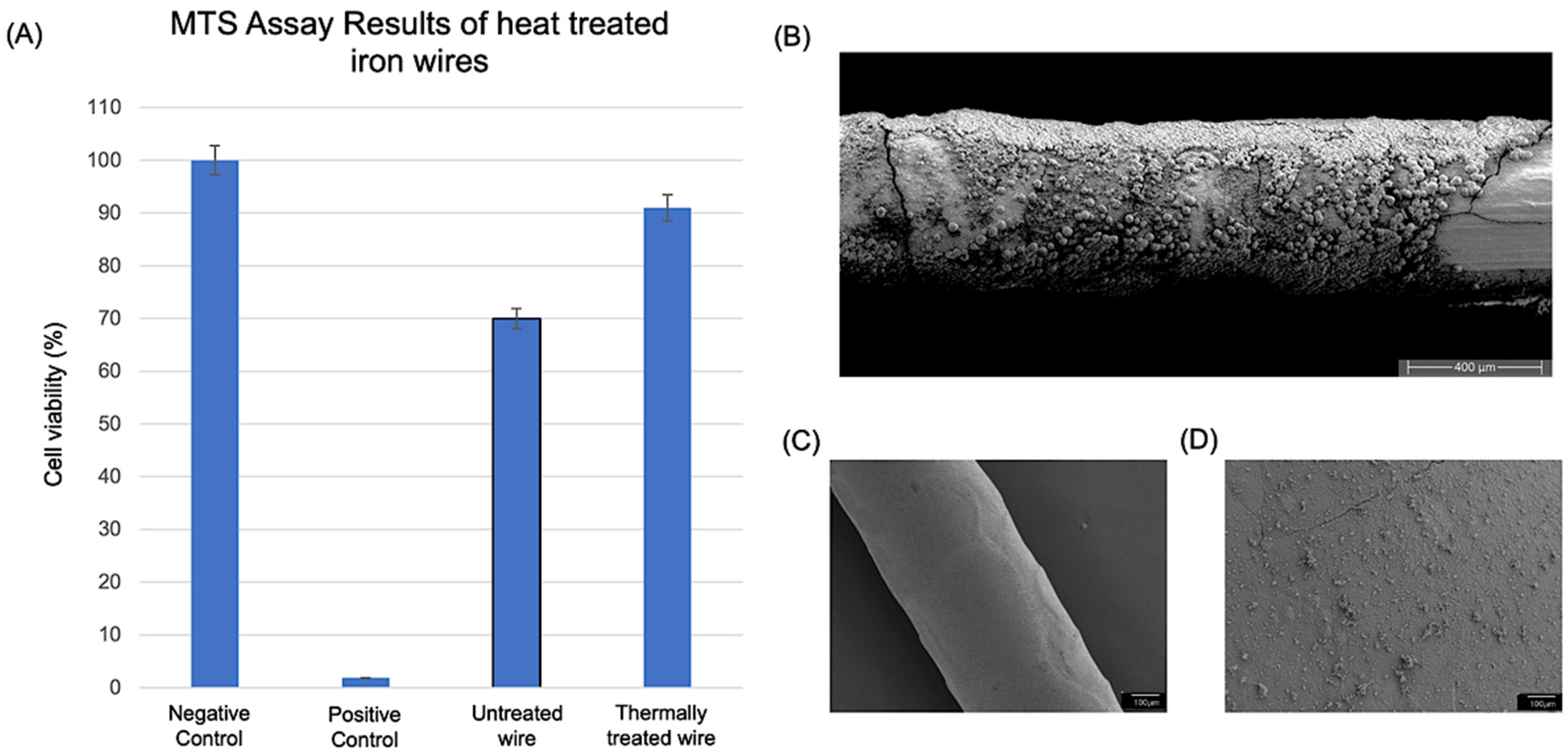
3.2. Biocompatibility Study Results
3.3. Prototype Fabrication
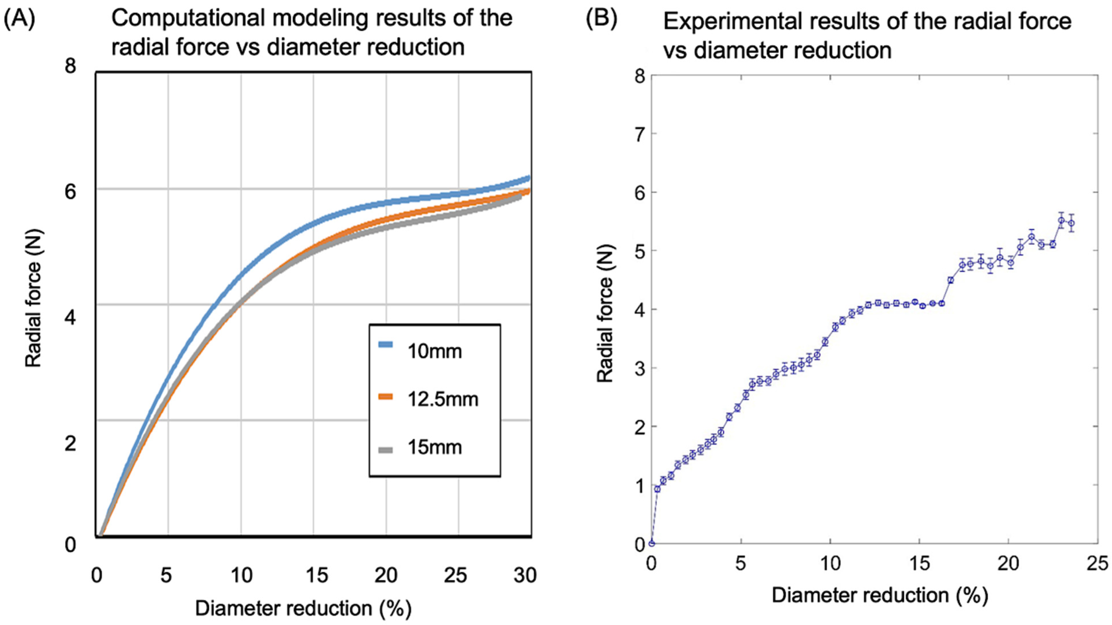
3.4. Radial Strength Analysis and Experimental Validation
3.4.1. Computational Modeling Results of the Stress vs. Strain of the Valve Frame
3.4.2. Comparison of Computational Modeling and Experimental Results on Radial Strength
4. Discussion
5. Conclusions
Author Contributions
Funding
Institutional Review Board Statement
Informed Consent Statement
Data Availability Statement
Conflicts of Interest
References
- Loffredo, C.A. Epidemiology of cardiovascular malformations: Prevalence and risk factors. Am. J. Med. Genet. 2000, 97, 319–325. [Google Scholar] [CrossRef] [PubMed]
- Friedewald, V.E.; Bonow, R.O.; Borer, J.S.; Carabello, B.A.; Kleine, P.P.; Akins, C.W.; Roberts, W.C. The editor’s roundtable: Cardiac valve surgery. Am. J. Cardiol. 2007, 99, 1269–1278. [Google Scholar] [CrossRef] [PubMed]
- Association, A.H. Heart Disease and Stroke Statistics—2004 Update; American Heart Association: Dallas, TX, USA, 2004. [Google Scholar]
- iData Research. Cardiac Surgery Market Size, Share, and COVID-19 Impact Analysis; iData Research: Burnaby, BC, Canada, 2020. [Google Scholar]
- Kidane, A.G.; Burriesci, G.; Cornejo, P.; Dooley, A.; Sarkar, S.; Bonhoeffer, P.; Edirisinghe, M.; Seifalian, A.M. Current developments and future prospects for heart valve replacement therapy. J. Biomed. Mater. Res. Part B Appl. Biomater. 2009, 88, 290–303. [Google Scholar] [CrossRef] [PubMed]
- Vongpatanasin, W.; Hillis, L.D.; Lange, R.A. Prosthetic heart valves. N. Engl. J. Med. 1996, 335, 407–416. [Google Scholar] [CrossRef] [PubMed]
- Cobanoglu, A.; Fessler, C.L.; Guvendik, L.; Grunkemeier, G.; Starr, A. Aortic valve replacement with the Starr-Edwards prosthesis: A comparison of the first and second decades of follow-up. Ann. Thorac. Surg. 1988, 45, 248–252. [Google Scholar] [CrossRef]
- Schoevaerdts, J.C.; Buche, M.; El Gariani, A.; Lichtsteiner, M.; Jaumin, P.; Ponlot, R.; Chalant, C. Twenty years’ experience with the Model 6120 Starr-Edwards valve in the mitral position. J. Thorac. Cardiovasc. Surg. 1987, 94, 375. [Google Scholar] [CrossRef]
- Head, S.J.; Çelik, M.; Kappetein, A.P. Mechanical versus bioprosthetic aortic valve replacement. Eur. Heart J. 2017, 38, 2183–2191. [Google Scholar] [CrossRef]
- Gallegos, R.P.; Rivard, A.L.; Suwan, P.T.; Black, S.; Bertog, S.; Steinseifer, U.; Armien, A.; Lahti, M.; Bianco, R.W. In-vivo experience with the Triflo trileaflet mechanical heart valve. J. Heart Valve Dis. 2006, 15, 791. [Google Scholar]
- Wu, Y.X.; Gregorio, R.; Renzulli, A.; Onorati, F.; De Feo, M.; Grunkemeier, G.; Cotrufo, M. Mechanical heart valves: Are two leaflets better than one? J. Thorac. Cardiovasc. Surg. 2004, 127, 1171–1179. [Google Scholar] [CrossRef]
- Lim, K.H.H.; Caputo, M.; Ascione, R.; Wild, J.; West, R.; Angelini, G.D.; Bryan, A.J.; Calafiore, S.; Maria, A. Prospective randomized comparison of CarboMedics and St Jude Medical bileaflet mechanical heart valve prostheses: An interim report. J. Thorac. Cardiovasc. Surg. 2002, 123, 21–32. [Google Scholar] [CrossRef]
- Gregoric, I.D.; Eya, K.; Tamez, D.; Cervera, R.; Byler, D.; Conger, J.; Tuzun, E.; Chee, H.K.; Clubb, F.J.; Kadipasaoglu, K. Preclinical hemodynamic assessment of a new trileaflet mechanical valve in the aortic position in a bovine model. J. Heart Valve Dis. 2004, 13, 254. [Google Scholar]
- Schoen, F.J.; Levy, R.J. Tissue heart valves: Current challenges and future research perspectives. J. Biomed. Mater. Res. 1999, 47, 439–465. [Google Scholar] [CrossRef]
- Wells, S.M.; Sellaro, T.; Sacks, M.S. Cyclic loading response of bioprosthetic heart valves: Effects of fixation stress state on the collagen fiber architecture. Biomaterials 2005, 26, 2611–2619. [Google Scholar] [CrossRef]
- Sacks, M.S.; Schoen, F.J. Collagen fiber disruption occurs independent of calcification in clinically explanted bioprosthetic heart valves. J. Biomed. Mater. Res. 2002, 62, 359–371. [Google Scholar] [CrossRef]
- Schoen, F.J.; Levy, R.J. Calcification of tissue heart valve substitutes: Progress toward understanding and prevention. Ann. Thorac. Surg. 2005, 79, 1072–1080. [Google Scholar] [CrossRef]
- Yacoub, M.; Rasmi, N.R.H.; Sundt, T.M.; Lund, O.; Boyland, E.; Radley-Smith, R.; Khaghani, A.; Mitchell, A. Fourteen-year experience with homovital homografts for aortic valve replacement. J. Thorac. Cardiovasc. Surg. 1995, 110, 186–194. [Google Scholar] [CrossRef]
- O’Brien, M.F.; Gregory Stafford, E.; Gardner, M.A.H.; Pohlner, P.G.; Tesar, P.J.; Cochrane, A.D.; Mau, T.K.; Gall, K.L.; Smith, S.E. Allograft aortic valve replacement: Long-term follow-up. Ann. Thorac. Surg. 1995, 60, S65–S70. [Google Scholar] [CrossRef]
- Bloomfield, P.; Wheatley, D.J.; Prescott, R.J.; Miller, H.C. Twelve-year comparison of a Bjork–Shiley mechanical heart valve with porcine bioprostheses. N. Engl. J. Med. 1991, 324, 573–579. [Google Scholar] [CrossRef]
- Busch, J.; Johnson, A.; Lee, C.; Stevenson, D. Shape-memory properties in Ni-Ti sputter-deposited film. J. Appl. Phys. 1990, 68, 6224–6228. [Google Scholar] [CrossRef]
- Szold, A. Nitinol: Shape-memory and super-elastic materials in surgery. Surg. Endosc. 2006, 20, 1493–1496. [Google Scholar] [CrossRef]
- Machado, L.; Savi, M. Medical applications of shape memory alloys. Braz. J. Med. Biol. Res. 2003, 36, 683–691. [Google Scholar] [CrossRef] [PubMed]
- Shabalovskaya, S.A. Surface, corrosion and biocompatibility aspects of Nitinol as an implant material. Bio-Med. Mater. Eng. 2002, 12, 69–109. [Google Scholar]
- Moravej, M.; Mantovani, D. Biodegradable metals for cardiovascular stent application: Interests and new opportunities. Int. J. Mol. Sci. 2011, 12, 4250–4270. [Google Scholar] [CrossRef] [PubMed]
- Peuster, M.; Hesse, C.; Schloo, T.; Fink, C.; Beerbaum, P.; von Schnakenburg, C. Long-term biocompatibility of a corrodible peripheral iron stent in the porcine descending aorta. Biomaterials 2006, 27, 4955–4962. [Google Scholar] [CrossRef]
- Batista, B.A.; Soares, R.B.; Lins, V.d.F.C.; Figueiredo, R.B.; Hohenwarter, A.; Matencio, T. Corrosion in hank’s solution and mechanical strength of ultrafine-grained pure iron. Adv. Eng. Mater. 2020, 22, 2000183. [Google Scholar] [CrossRef]
- Obayi, C.S.; Tolouei, R.; Mostavan, A.; Paternoster, C.; Turgeon, S.; Okorie, B.A.; Obikwelu, D.O.; Mantovani, D. Effect of grain sizes on mechanical properties and biodegradation behavior of pure iron for cardiovascular stent application. Biomatter 2016, 6, e959874. [Google Scholar] [CrossRef]
- Marciuš, M.; Ristić, M.; Ivanda, M.; Musić, S. Formation of iron oxides by surface oxidation of iron plate. Croat. Chem. Acta 2012, 85, 117–124. [Google Scholar] [CrossRef]
- Simmons, G.; Kellerman, E.; Leidheiser, H., Jr. The oxidation of iron as studied by conversion electron Mössbauer spectroscopy. Corrosion 1973, 29, 227. [Google Scholar] [CrossRef]
- Yan, R.; Gao, X.; He, W.; Guo, R.; Wu, R.; Zhao, Z.; Ma, H. A simple and convenient method to fabricate new types of phytic acid–metal conversion coatings with excellent anti-corrosion performance on the iron substrate. RSC Adv. 2017, 7, 41152–41162. [Google Scholar] [CrossRef]
- Gu, X.; Mao, Z.; Ye, S.-H.; Koo, Y.; Yun, Y.; Tiasha, T.R.; Shanov, V.; Wagner, W.R. Biodegradable, elastomeric coatings with controlled anti-proliferative agent release for magnesium-based cardiovascular stents. Colloids Surf. B Biointerfaces 2016, 144, 170–179. [Google Scholar] [CrossRef]
- Liu, L.; Ye, S.-H.; Gu, X.; Russell, T.; Xu, Z.; Sankar, J.; Wagner, W.R.; Lee, Y.-C.; Yun, Y. Comparison of endothelial cell attachment on surfaces of biodegradable polymer-coated magnesium alloys in a microfluidic environment. PLoS ONE 2018, 13, e0205611. [Google Scholar] [CrossRef]
- Wu, W.; Qi, M.; Liu, X.-P.; Yang, D.-Z.; Wang, W.-Q. Delivery and release of nitinol stent in carotid artery and their interactions: A finite element analysis. J. Biomech. 2007, 40, 3034–3040. [Google Scholar] [CrossRef]
- Kim, S.; Nowicki, K.W.; Ye, S.; Jang, K.; Elsisy, M.; Ibrahim, M.; Chun, Y.; Gross, B.A.; Friedlander, R.M.; Wagner, W.R. Bioabsorbable, elastomer-coated magnesium alloy coils for treating saccular cerebrovascular aneurysms. Biomaterials 2022, 290, 121857. [Google Scholar] [CrossRef]
- Ye, S.-H.; Arazawa, D.T.; Zhu, Y.; Shankarraman, V.; Malkin, A.D.; Kimmel, J.D.; Gamble, L.J.; Ishihara, K.; Federspiel, W.J.; Wagner, W.R. Hollow fiber membrane modification with functional zwitterionic macromolecules for improved thromboresistance in artificial lungs. Langmuir 2015, 31, 2463–2471. [Google Scholar] [CrossRef]
- Lutter, G.; Ardehali, R.; Cremer, J.; Bonhoeffer, P. Percutaneous valve replacement: Current state and future prospects. Ann. Thorac. Surg. 2004, 78, 2199–2206. [Google Scholar] [CrossRef]
- El-Omar, M.M.; Dangas, G.; Iakovou, I.; Mehran, R. Update on in-stent restenosis. Curr. Interv. Cardiol. Rep. 2001, 3, 296–305. [Google Scholar]
- Schömig, A.; Kastrati, A.; Mudra, H.; Blasini, R.; Schühlen, H.; Klauss, V.; Richardt, G.; Neumann, F.J. Four-year experience with Palmaz-Schatz stenting in coronary angioplasty complicated by dissection with threatened or present vessel closure. Circulation 1994, 90, 2716–2724. [Google Scholar] [CrossRef]
- Finotello, A.; Gorla, R.; Brambilla, N.; Bedogni, F.; Auricchio, F.; Morganti, S. Finite element analysis of transcatheter aortic valve implantation: Insights on the modelling of self-expandable devices. J. Mech. Behav. Biomed. Mater. 2021, 123, 104772. [Google Scholar] [CrossRef]
- Salemizadeh Parizi, F.; Mehrabi, R.; Karamooz-Ravari, M.R. Finite element analysis of NiTi self-expandable heart valve stent. Proc. Inst. Mech. Eng. Part H J. Eng. Med. 2019, 233, 1042–1050. [Google Scholar] [CrossRef]
- Elsisy, M.; Tillman, B.W.; Go, C.; Kuhn, J.; Cho, S.K.; Clark, W.W.; Park, J.; Chun, Y. Comprehensive assessment of mechanical behavior of an extremely long stent graft to control hemorrhage in torso. J. Biomed. Mater. Res. Part B Appl. Biomater. 2020, 108, 2192–2203. [Google Scholar] [CrossRef]
- Egron, S.; Fujita, B.; Gullón, L.; Pott, D.; Schmitz-Rode, T.; Ensminger, S.; Steinseifer, U. Radial force: An underestimated parameter in oversizing transcatheter aortic valve replacement prostheses: In vitro analysis with five commercialized valves. ASAIO J. 2018, 64, 536–543. [Google Scholar] [CrossRef]
- Elsisy, M.; Shayan, M.; Chen, Y.; Tillman, B.W.; Go, C.; Chun, Y. Assessment of mechanical and biocompatible performance of ultra-large nitinol endovascular devices fabricated via a low-energy laser joining process. J. Biomater. Appl. 2021, 36, 332–345. [Google Scholar] [CrossRef] [PubMed]
- MI, K.; Zhou, Y. Effects of welding parameters on the mechanical performance of laser welded nitinol. Mater. Trans. 2008, 49, 2702–2708. [Google Scholar]
- Deepan Bharathi Kannan, T.; Ramesh, T.; Sathiya, P. A review of similar and dissimilar micro-joining of nitinol. JOM 2016, 68, 1227–1245. [Google Scholar] [CrossRef]
- Moeri, L.; Lichtenberg, M.; Gnanapiragasam, S.; Barco, S.; Sebastian, T. Braided or laser-cut self-expanding nitinol stents for the common femoral vein in patients with post-thrombotic syndrome. J. Vasc. Surg. Venous Lymphat. Disord. 2021, 9, 760–769. [Google Scholar] [CrossRef]
- van Veenendaal, P.; Maingard, J.; Kok, H.K.; Ranatunga, D.; Buckenham, T.; Chandra, R.V.; Lee, M.J.; Brooks, D.M.; Asadi, H. Endovascular flow-diversion of visceral and renal artery aneurysms using dual-layer braided nitinol carotid stents. CVIR Endovasc. 2020, 3, 33. [Google Scholar] [CrossRef]
- Zheng, Q.; Mozafari, H.; Li, Z.; Gu, L.; An, M.; Han, X.; You, Z. Mechanical characterization of braided self-expanding stents: Impact of design parameters. J. Mech. Med. Biol. 2019, 19, 1950038. [Google Scholar] [CrossRef]


Disclaimer/Publisher’s Note: The statements, opinions and data contained in all publications are solely those of the individual author(s) and contributor(s) and not of MDPI and/or the editor(s). MDPI and/or the editor(s) disclaim responsibility for any injury to people or property resulting from any ideas, methods, instructions or products referred to in the content. |
© 2023 by the authors. Licensee MDPI, Basel, Switzerland. This article is an open access article distributed under the terms and conditions of the Creative Commons Attribution (CC BY) license (https://creativecommons.org/licenses/by/4.0/).
Share and Cite
Ibrahim, M.; Nghiem, K.X.; Chung, K.; Elsisy, M.; Gosai, U.J.; Kim, S.; Ye, S.; Wagner, W.R.; Chun, Y. A Novel Low-Profile Self-Expanding Biodegradable Percutaneous Heart Valve Frame That Grows with a Child. Coatings 2023, 13, 184. https://doi.org/10.3390/coatings13010184
Ibrahim M, Nghiem KX, Chung K, Elsisy M, Gosai UJ, Kim S, Ye S, Wagner WR, Chun Y. A Novel Low-Profile Self-Expanding Biodegradable Percutaneous Heart Valve Frame That Grows with a Child. Coatings. 2023; 13(1):184. https://doi.org/10.3390/coatings13010184
Chicago/Turabian StyleIbrahim, Mohamed, Kara X. Nghiem, Kaitlin Chung, Moataz Elsisy, Uma J. Gosai, Seungil Kim, Sangho Ye, William R. Wagner, and Youngjae Chun. 2023. "A Novel Low-Profile Self-Expanding Biodegradable Percutaneous Heart Valve Frame That Grows with a Child" Coatings 13, no. 1: 184. https://doi.org/10.3390/coatings13010184
APA StyleIbrahim, M., Nghiem, K. X., Chung, K., Elsisy, M., Gosai, U. J., Kim, S., Ye, S., Wagner, W. R., & Chun, Y. (2023). A Novel Low-Profile Self-Expanding Biodegradable Percutaneous Heart Valve Frame That Grows with a Child. Coatings, 13(1), 184. https://doi.org/10.3390/coatings13010184