Article

Electroless Ni-P-PTFE Composite Plating with Rapid Deposition and High PTFE Concentration through a Two-Step Process

1
Graduate School of Convergence Science, Pusan National University, Busan 462461, Korea
2
Business Support Division Analysis & Certification Center, Korea Institute of Ceramic Engineering & Technology, Jinju 52851, Korea
3
National Core Research Center for Hybrid Materials Solution and Global Frontier R&D Center for Hybrid Interface Materials, Pusan National University, Busan 462461, Korea
*
Author to whom correspondence should be addressed.
Coatings 2022, 12(8), 1199; https://doi.org/10.3390/coatings12081199
Submission received: 6 July 2022 / Revised: 4 August 2022 / Accepted: 8 August 2022 / Published: 17 August 2022
(This article belongs to the Special Issue Advances in Novel Coatings)

Abstract

:
Electroless composite plating enables uniform and thin surface treatment along with composite deposition using nanoparticles. Among such particles, polytetrafluoroethylene (PTFE) is capable of dry lubrication because of its self-lubricating properties. Specifically, the PTFE content in a plating layer increases with the concentration of PTFE in the plating bath. However, a high concentration of PTFE interferes with the co-deposition of Ni and P, thereby reducing the plating speed. Additionally, PTFE is unevenly deposited on the surface of the plating layer. Consequently, a method for increasing the PTFE content at low PTFE concentrations is required. Therefore, in this study, a stirring process in a low-PTFE-concentration plating bath and a process wherein PTFE precipitates on a specimen without stirring were combined. The PTFE content of the plated layer deposited on high carbon steel, plated layer deposition rate, average friction co-efficient, static contact angle, and surface energy were evaluated as 25.96%, 3.44 µm/40 min, 0.195, 141.9°, and 2.74 mN/m, respectively. This technique prevented the decrease in the deposition rate of the plating layer and led to high PTFE content in the plating layer. Notably, even a thin plating layer (5 μm or less in thickness) showed excellent surface characteristics.

1. Introduction

Superhydrophobic surfaces have varied and valuable impacts in industrial applications, as their high water repellency promotes self-cleaning and anti-icing mechanisms. For a material surface to be superhydrophobic (i.e., to have a water contact angle greater than 150°), the surface architecture and chemistry should be concurrently considered as two key aspects. A rough morphology and a waxy nonpolar coating, similar to those of lotus leaves, form hierarchical double layers and minimize the adhesion of water droplets to the surface. Consequently, various techniques have been developed to attain superhydrophobic properties on material surfaces by mimicking the lotus-leaf effect. Top-down approaches, including lithography, templating, and etching, remove materials from surfaces to produce an appropriate surface roughness, whereas bottom-up methods, such as chemical vapor deposition, electrochemical deposition, and sol-gel reactions deposit materials onto rough surfaces. Using nanotechnology, these techniques successfully produce elaborate fine nanostructures with superhydrophobicity even from hydrophilic materials. However, these morphology-focused techniques have limited use cases with respect to industrial applications, particularly regarding metal-based surfaces, because their delicate surface shapes entail high fabrication costs and are extremely vulnerable to abrasion [1,2,3,4].
In recent decades, electroless plating has been researched as an effective surface engineering tool to provide wear and corrosion resistance to various metallic materials [5,6]. The chemical reduction of metal ions in an aqueous solution containing reducing agents induces deposition with uniform thickness and composition, even when considering complex geometries. Furthermore, the coating properties can be readily tuned based on an appropriate choice of the solution composition, temperature, and pH. Another significant advantage of electroless plating compared with electroplating is its excellent compatibility with various materials such as steel, ceramics, carbon, and hydrophobic polymers, which facilitates composite coatings and imparts new surface properties. Notably, electroless deposition plating typically includes phosphorous or boron as derivatives from the reducing agent, and Ni-P alloys have been prevalently deposited owing to their high hardness, lubricity, and ductility. In addition, ceramics such as SiC and Al2O3 have been mixed with the Ni-P deposits to further enhance the hardness of the plating layer [7,8,9]. Moreover, the use of carbon nanotubes (CNTs) significantly improved corrosion resistance [10], and Gao et al. showed that the introduction of TiN nanoparticles provides corrosion resistance and electrical conductivity to the coatings [11].
Polytetrafluoroethylene (PTFE) provides low surface energy, imparting superhydrophobicity to Ni-P coatings. PTFE has been widely acknowledged as a material with exceptional non-stick properties; therefore, it has excellent potential as a dry lubricant. These properties of PTFE can improve dry lubrication and impart a low coefficient of friction, along with anti-fouling, anti-icing, anti-corrosion, and anti-contamination properties [12,13,14]. However, the addition of PTFE reduces the mechanical properties, which is a notable disadvantage. To solve this problem, Ni3P was precipitation-hardened at 300–350 °C to improve its mechanical properties [15].
Substantial research has already been conducted on Ni-P-PTFE plating, and the technique has been widely used in applications wherein self-lubrication and a low friction coefficient are required, such as in valves, train rails, and molds [16,17]. The Ni-P-PTFE plating layer shows outstanding performance, such as a low friction coefficient, excellent wear resistance, high contact angle, and low surface energy, as the content of PTFE increases [18,19,20]. To increase the PTFE content of the plating layer, a surfactant of an appropriate concentration is required to disperse the particles. Additionally, the concentration of PTFE must be increased in the plating bath. However, the content of solid particles in the plating bath also increases concurrently, causing several problems. The aggregation of high-concentration PTFE particles reduces the co-deposition rate of Ni-P and PTFE, interfering with uniform plating [21]; the size and outline of the particles also play an important role in the obtained plating layer [22]. To solve the aforementioned problem, a method to increase the PTFE content co-deposited at a low PTFE concentration level is required.
In this paper, a new electroless plating method is proposed to increase the PTFE content in the plating layer, prevent PTFE agglomeration, and increase the co-deposition rate even at low PTFE concentrations. In contrast to the existing plating method, an additional step was introduced in this method. The first step was to place the specimen on the floor, after which it was prepared for co-deposition based on the principle that solid particles settle without stirring. The second step was plating using the existing stirring method. Owing to the new plating method, excellent wear resistance and low surface energy can be expected even at low concentrations of PTFE. Additionally, various plating layer studies have been performed to research plating layers thicker than 10 μm [15]. If a thinner plating layer is applied, the precision of the product increases. In this study, an electroless composite plated layer comprising a Ni-P-PTFE thin film, expected to be less than 5 μm thick, on high-carbon steel, was analyzed.

2. Experimental

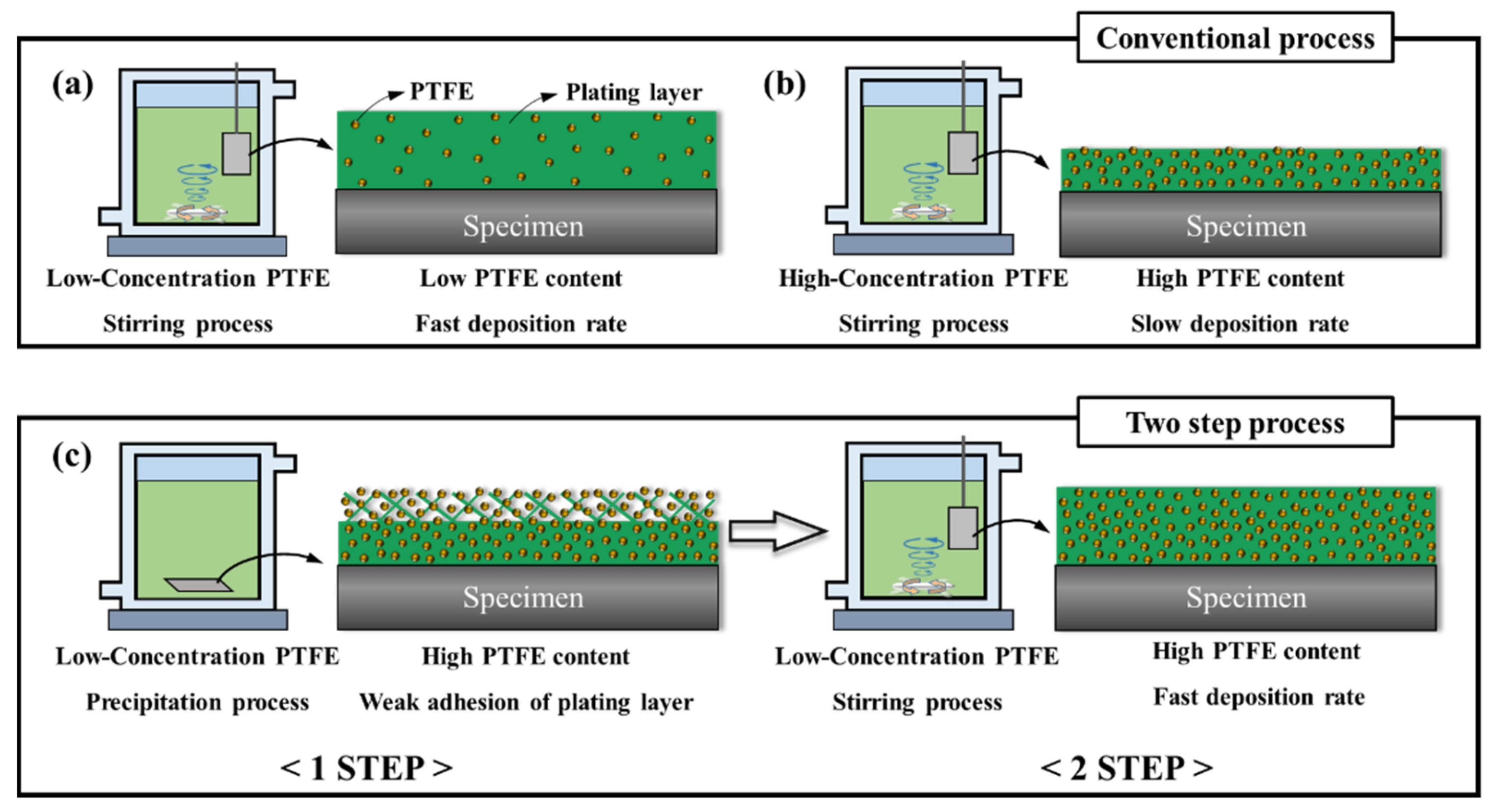
2.1. Conventional Process for Electroless Ni-P-PTFE Composite Plating

A 30 mm × 30 mm × 2 mm high-carbon steel, whose chemical composition is presented in Table 1, was used as the specimen for plating. First, the specimen was sonicated in a NaOH aqueous solution (10 wt.% and 40 °C) for 20 min to remove the surface-coated oils. Subsequently, acid activation was performed with HCl solution (6 M), followed by washing with deionized (DI) water. For the electroless plating process, an aqueous solution containing PTFE particles (NiSLIPTM 500; Surface Technology, Inc., Ewing Township, NJ, USA) was subjected to ultrasonic treatment at 40 °C for 1 h to prevent particle agglomeration and was then added to the Ni-P plating solution (Entech 512 HP-A; WYK Chemical Pte Ltd., Singapore), and the concentration of the particles was varied from 1 to 9 g/L. This Ni-P plating solution was composed of nickel acetate, sodium hypophosphite, and lactic acid and had a pH of 5. After the addition, the PTFE-mixed Ni-P solution was uniformly dispersed by stirring at 200 rpm for 1 h. The high-carbon steel specimen was then immersed in the resulting plating bath for 40 min while maintaining its temperature at 88 °C through a double-wall beaker.

2.2. Two-Step Process for Electroless Ni-P-PTFE Composite Plating

In this new technique, the electroless Ni-P-PTFE composite plating is realized by continuous precipitation and stirring steps, unlike the conventional approach. In the first step, the high-carbon steel specimen was placed in the same plating solution for 20 min, which induced excessive co-deposition of the PTFE particles onto the specimen surface. Next, while stirring the solution, the specimen was further coated by a nickel matrix with embedded PTFE particles (20 min), which significantly increased the degree of PTFE adhesion. This method is shown in Figure 1c. a and b are the conventional methods using only stirring at various concentrations.

2.3. Characterization

The size distribution of the PTFE particles was measured by laser diffraction analysis (LA-960, HORIBA, Kyoto, Japan). Field emission scanning electron microscopes (FESEM) (S-4800N, Hitachi, Tokyo, Japan) were used to examine the thickness of the plating layer and distribution of PTFE within the plating layer. X-ray diffraction (XRD) data were recorded on a Bruker D8 Discover (USA) with a scan speed of 0.2 s/step and a scan range of 10 to 90°. The friction coefficient was determined using a ball-on-disk apparatus (J&L TECH, Ansan-si, Korea), where the applied load was 1 N, sliding distance was 80 m, the SUS440C counterpart ball (7.9 mm) was used, and the rotation speed was 60 rpm. Wear track analysis was performed using an optical microscope (KH-8700, HIROX, Japan). The surface contact angles were measured by SmartDrop Plus_HS (FEMTOBIOMED, Seongnam-si, Korea); specifically, the static contact angle measurement method was employed with 3 μL droplets. The value of the static contact angle was obtained from the average of five measurements at random locations. The advancing contact angles were measured by averaging three measurement results, and the surface tension on the liquid–vapor interface was calculated using the pendant drop method.

3. Results and Discussion

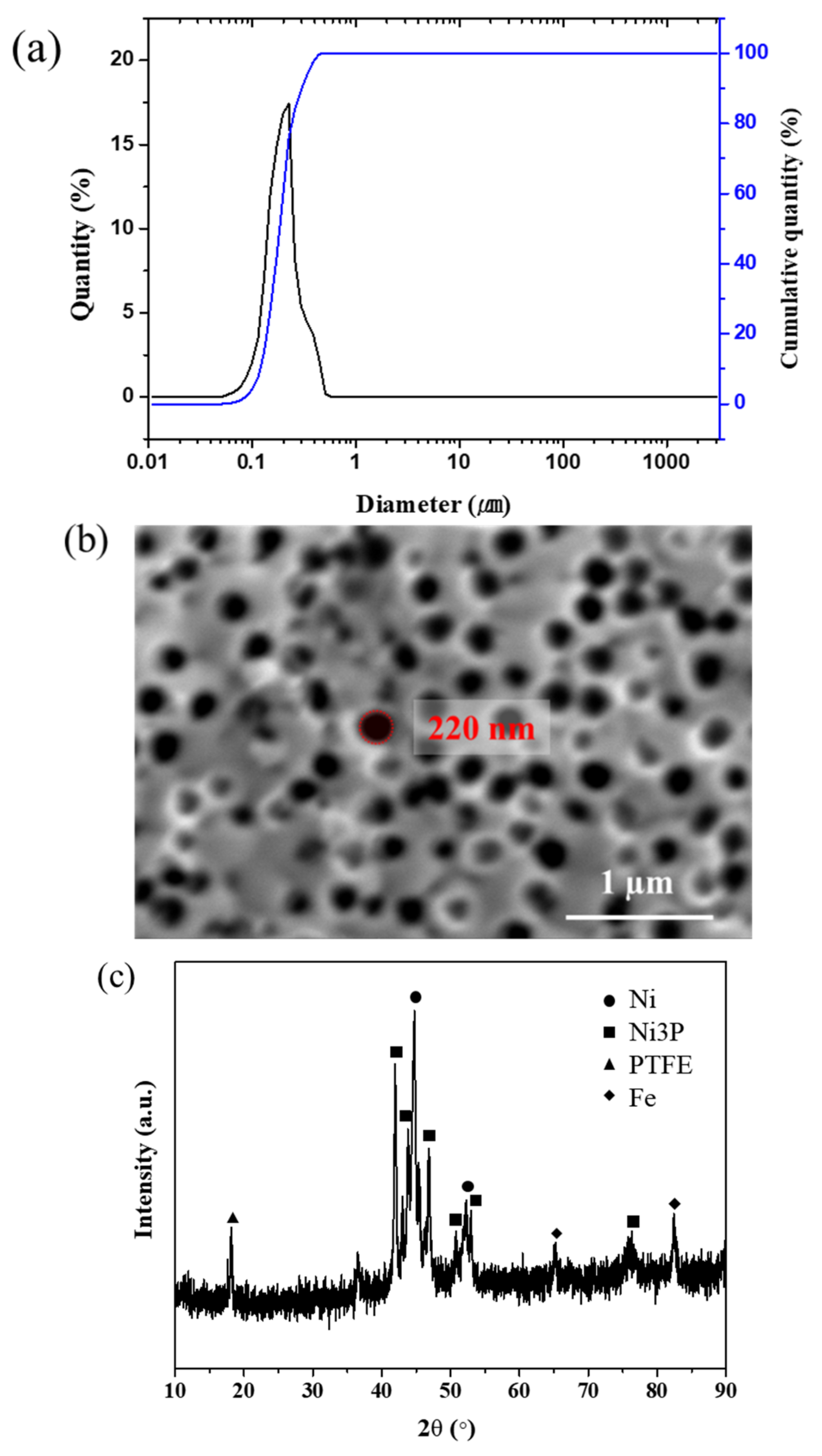
3.1. Size Distribution and Characteristics of PTFE Particles

The particle size distribution analysis of the PTFE aqueous solution was completed using the laser diffraction method. Notably, 17.45% of the particles exhibited a size of 226 nm. The second most common particle size was 197 nm, corresponding to 16.77% of the particles. Further, the particles exhibited a unimodal distribution. Figure 2b shows the surface image of the plating layer, obtained using an SEM. One should note that the diameter of the PTFE particles is uniform, approximately 200 nm. Moreover, these measurements are consistent with the laser-diffraction particle size analysis. Additionally, the PTFE is uniformly distributed in the plating layer. Figure 2c shows the result of an XRD analysis of the surface of the plating layer. It was confirmed that the PTFE was observed at 2θ = 18°, Ni diffraction peaks at 2θ = 44.5°, 51.8°, Ni3P diffraction peaks at 2θ = 40° to 58°, and Fe diffraction peaks at 2θ = 64.1° and 82.1° [15]. In composite plating, if the particle sizes of PTFE, SiC, and Al2O3 are not uniform, the agglomeration of particles occurs, hindering the uniform dispersion of PTFE in the plating bath. As a result, the particle concentration in the plating layer decreases, and the roughness of the surface is increased [20,23]. The size uniformity of the PTFE particles is essential to obtain an optimum Ni-P-PTFE plating layer.

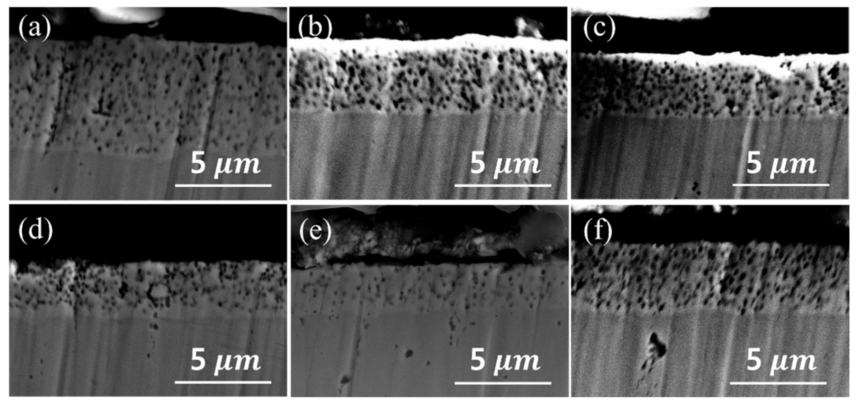
3.2. Precipitation Characterization of Ni–PTFE Composite Plating

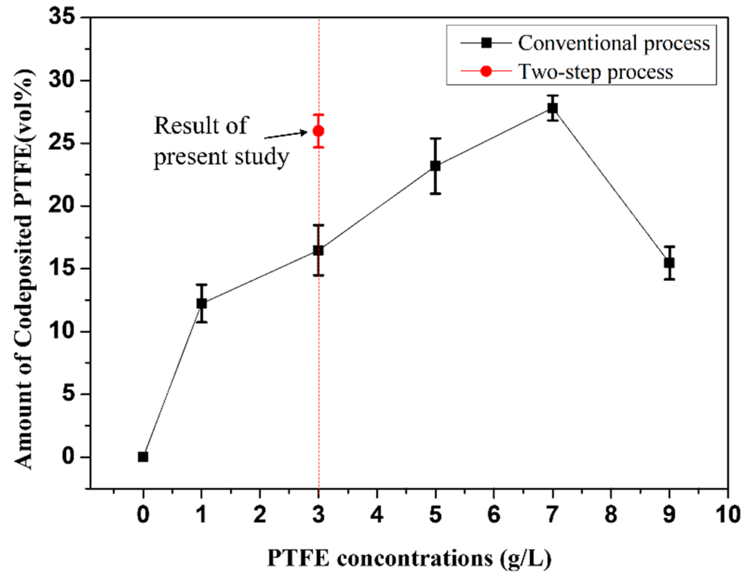
3.2.1. Plating Deposition Rate and PTFE Content of Plating Layer

When PTFE is added to the Ni-P plating layer, dry lubrication performance is improved. The greater the PTFE content in the plating layer, the better the dry lubrication performance. The PTFE co-deposition rate was further enhanced by increasing the PTFE concentration in the plating bath [24]. As shown in Figure 1a,b, the higher the concentration of PTFE in the plating bath, the greater the amount of PTFE in the plating layer. From Figure 3, it can be seen that the amount of co-deposited PTFE increased with the PTFE concentration in the plating bath. However, it decreased at 9 g/L of PTFE because the high concentration of particles hindered the co-deposition [21]. Figure 4 shows that the higher the PTFE concentration in the plating bath, the slower the deposition rate. These results are similar to those of the plating layer thickness in Figure 1a,b. In the experiments using stirring, the plating layer thickness was 5.68, 3.45, 3.11, 2.66, and 2.1 μm at 1, 3, 5, 7, and 9 g/L, respectively. From Figure 3 and Figure 4, when the concentration was 3 g/L, in the combined precipitation and stirring method, high PTFE content in the plating layer and a fast plating speed could be achieved. Figure 1c shows a similar result. When the precipitation and stirring processes were combined, there were small changes in the plating speed at the same concentration. At a 3 g/L concentration, the PTFE content in the plating layer was 25.96 vol%, and the plating thickness was 3.44 μm.

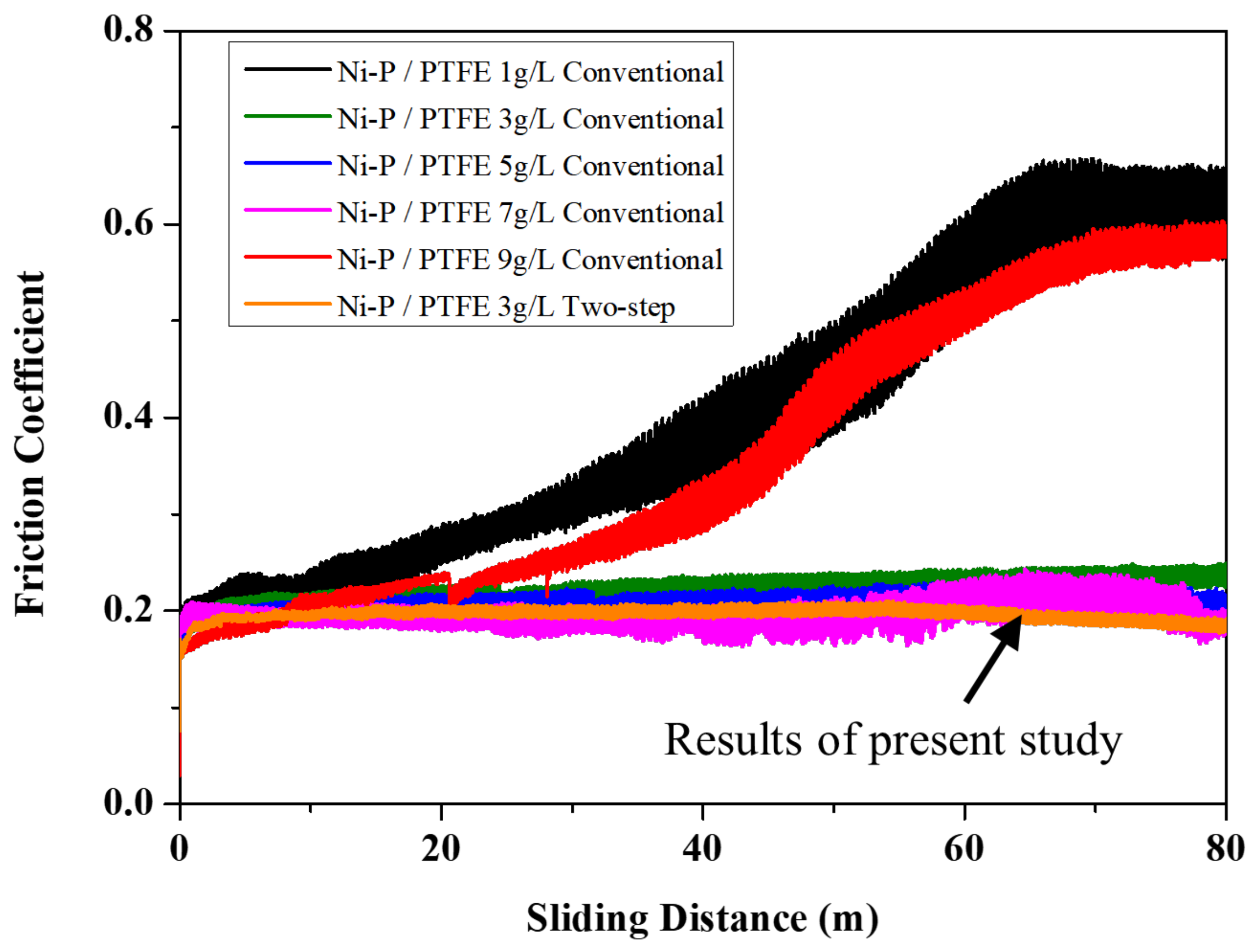
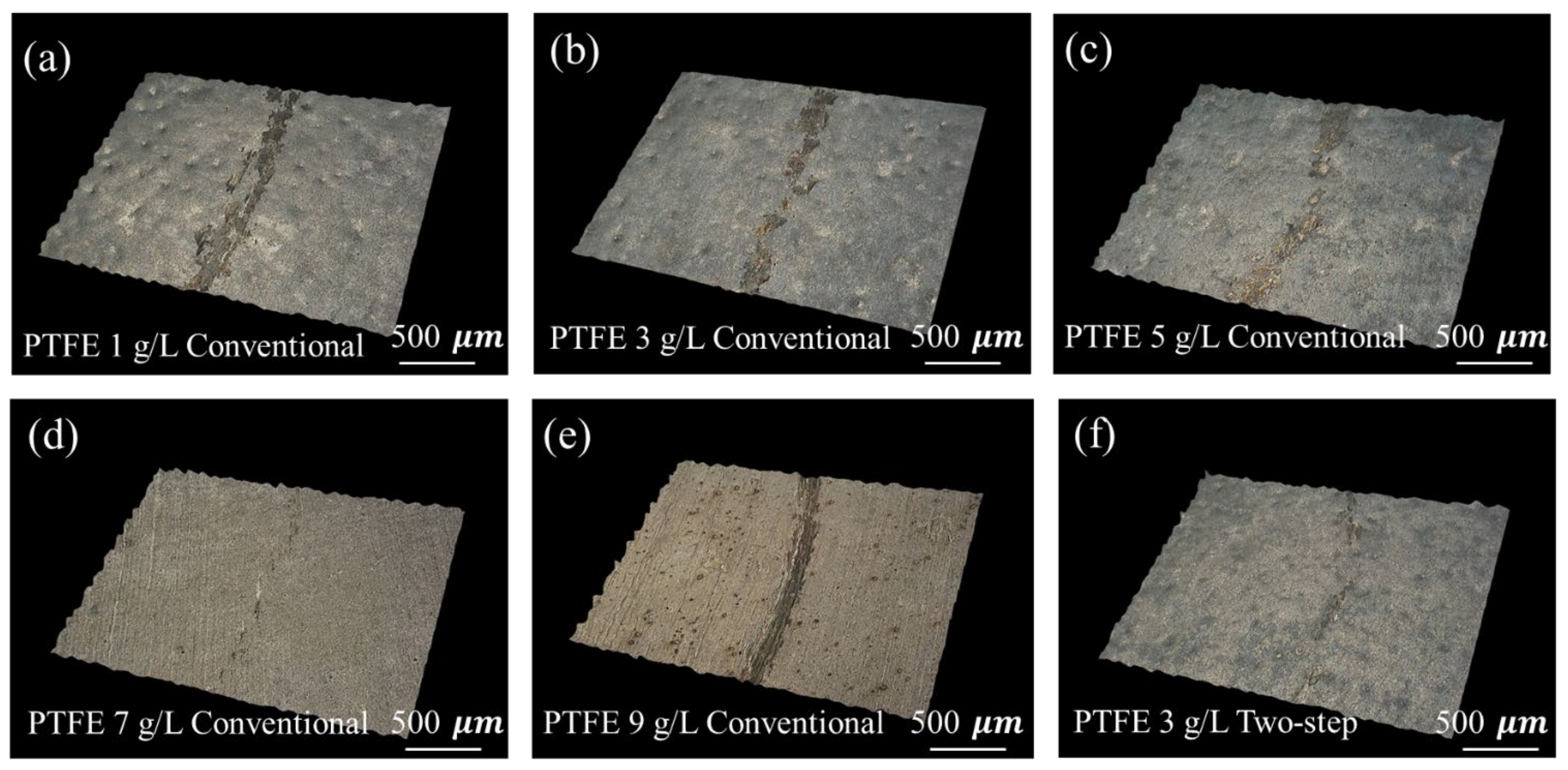
3.2.2. Friction Coefficient and Wear Resistance of Plating Layer

Figure 5 presents the coefficient of friction curve of the plating layer. The coefficient of friction of the plating layer was approximately 0.15 to 0.23, depending on the amount of PTFE. When the PTFE concentration was 1 and 9 g/L, the friction coefficient of the plated layer obtained using only stirring increased rapidly; this is because the PTFE plated layer started to wear at a sliding distance of approximately 10 m. At a 3 g/L concentration of PTFE, the friction coefficient of the plating layer obtained using only stirring was 0.201 at a sliding distance of 0 to 10 m and 0.232 at a sliding distance of 70 to 80 m. At a 5 g/L PTFE concentration, the coefficient of friction of the plating layer obtained using only stirring increased slightly to 0.195 at the sliding distance of 0 to 10 m and to 0.220 at a sliding distance of 70 to 80 m. When the PTFE concentration was 7 g/L, the friction coefficient of the plating layer obtained using only stirring was 0.16–0.23, exhibiting a wide range. This can be attributed to particle agglomeration and non-uniform plating at high concentrations. In the specimen obtained with combined precipitation and stirring at a PTFE concentration of 3 g/L, the average friction coefficient was the lowest, at 0.195. Specifically, the friction coefficients were 0.192 and 0.194 at sliding distances of 0–10 m and 70–80 m, respectively, with a small difference between the friction coefficients. The variation of the coefficient of friction was as small as 0.17–0.21, which indicates that the PTFE was uniformly plated without any agglomeration. Overall, as the content of PTFE increases, the coefficient of friction tends to decrease. The layer containing PTFE acts as a lubricant, reducing the coefficient of friction of the composite plating layer [25,26]. Typically, the wear resistance of plating is affected by the coefficient of friction and hardness [27]. When the coefficient of friction is low, the wear resistance performance is enhanced. Hence, the PTFE content in the plating layer is important.
Figure 6 shows the result of observing the worn surface with an optical microscope after measuring the PTFE concentration and the surface friction coefficient of the plating layers obtained according to the various plating methods. To improve the wear resistance, the surface hardness should be high, while the friction coefficient must be low [28]. The PTFE acts as a dry self-lubricant in the Ni-P-PTFE composite plating layer, and the lower friction improves the wear resistance. The plating layers obtained using only stirring at 7 g/L of PTFE and by the electroless composite plating method in which precipitation and stirring were combined at 3 g/L of PTFE showed almost no wear tracks. By contrast, in the electroless composite plating method using only stirring at 3 and 5 g/L of PTFE, the wear tracks confirmed that the Ni-P-PTFE plating layer was partially worn. These results show the changes observed upon the slight increase in the value of the coefficient of friction due to the wear of the plating layer in Figure 5. Further, in the electroless composite plating method using only stirring at 1 and 9 g/L of PTFE, the wear tracks confirmed that the Ni-P-PTFE plating layer was mostly worn. Based on these results, we notice that the PTFE content plays a crucial role in wear resistance [29].

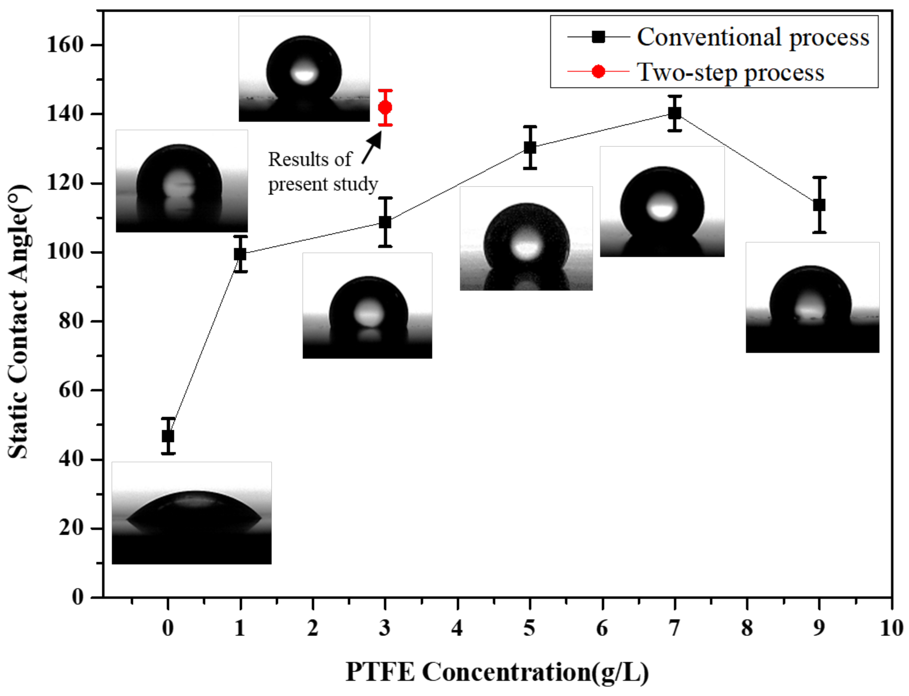
3.2.3. Static and Dynamic Contact Angle of Plating Layer

A notable characteristic of PTFE is its low surface energy. Adding PTFE particles to the Ni-P plating layer can improve its wetting properties. When the PTFE concentration in the plating bath was high, the PTFE content in the plating layer increased. The higher the PTFE concentration in the plating bath, the better the wetting characteristics and the superhydrophobicity [30]. Figure 7 presents the results of the static contact angle on the surface of the plating layer. The static contact angle of the Ni-P plating layer that did not contain PTFE was 46.8°. The experimental results show that the greater the PTFE content in the plating bath, the larger the contact angle, although when the PTFE concentration reached 9 g/L, the contact angle decreased. The co-deposition rate was reduced owing to the agglomeration of PTFE particles in the plating bath. The static contact angle of the layer plated by combined precipitation and stirring at a PTFE concentration of 3 g/L was 141.9°, which is substantially high. Notably, excellent hydrophobic properties were exhibited even when plating was performed in a low-PTFE-concentration plating bath. The relationship between the PTFE content in the plating layer and the contact angle can be confirmed by observing Figure 3 and Figure 7. Namely, the PTFE content in the plated layer and the static contact angle are proportional.
To determine the surface energy of the plating according to various PTFE concentrations and plating methods, the ambient temperature was measured at 27 °C, and the moisture was approximately 26%. The low surface energy of the plating plays a major role in properties such as low adhesion behavior and anti-icing [31]. The surface energy of the plating was calculated based on the following Young’s equation [32]:
cos θ Y = 1 + 2 γ SV γ LV e β γ LV γ SV 2   β = 0.0001247
where γLV is the liquid–vapor surface energy, γSV is the solid–vapor surface energy, γSL is the solid–liquid surface energy, θY is the advancing contact angle of the liquid on the solid, and β is a constant. The γLV measured by the pendant drop method was 70.51 (mN/m), which is different from the previously reported 72.8 (mN/m). This is because the water was not 100% pure. The γSV and γSL were calculated by combining Equations (1) and (2).
γ SV   =   γ SL   +   γ LV cos θ Y
Table 2 shows that the surface energy of the plating layer obtained by combined precipitation and stirring at a low concentration of PTFE (3 g/L) was 2.73 (mN/m). This is almost the same value as that obtained for plating fabricated at a high PTFE concentration of 7 g/L using stirring. Moreover, referring to Figure 3, the higher the PTFE content in the plating layer, the lower the surface energy. As a result, the PTFE content in the plating layer affects the surface energy.
In summary, as shown in Figure 8, when only the stirring process was used with low-concentration PTFE, the content of PTFE in the plating layer was low. When only stirring was used with high-concentration PTFE, the plating speed was lowered further, and the PTFE particles in the plating layer were agglomerated. However, if the precipitation and stirring processes were combined at a low PTFE concentration, high PTFE content was observed in the plating layer, along with a relatively high plating speed and prevention of particle agglomeration. As a result, high hydrophobicity, low coefficient of friction, excellent wear resistance, and uniform plating were achieved.

4. Conclusions

In this study, PTFE, which has low surface energy and can act as a self-lubricating material, was co-deposited with nickel and phosphorus on high-carbon steel. In Ni-P-PTFE electroless plating, the PTFE content in the plating layer increases with the PTFE content in the plating bath. However, when using the stirring method at the high concentration of 9 g/L, co-deposition was prevented owing to the agglomeration of particles. Furthermore, the plating speed was significantly reduced. A two-step process was used to increase the PTFE content in the plating layer by using Ni-P-PTFE electroless plating. This process involved the precipitation of PTFE and stirring of the plating solution. Using this method, the PTFE content in the plated layer was increased even at low concentrations of PTFE by using the precipitation phenomenon of PTFE. Upon using the two-step process, at a 3 g/L PTFE concentration, the PTFE content of the plating layer was 25.96 vol%, the average coefficient of friction was 0.196, the contact angle was 141.9°, and the surface energy of the plating was 2.73. The results demonstrated the excellent wear resistance and anti-fouling properties of the plating layer. This novel process can overcome the limitations of the existing electroless composite plating process by combining precipitation and stirring. It can further be applied in the field of functional surface treatment to increase the amount of co-deposition of particles.

Author Contributions

Conceptualization, M.L. and K.S.; methodology, J.P. and D.K.; validation, K.K. and M.K.; investigation, M.L. and J.P.; writing—original draft preparation, M.L. and K.S.; writing—review and editing, M.K.; supervision, M.K. and K.K.; project administration, M.L. and D.K. All authors have read and agreed to the published version of the manuscript.

Funding

This research was funded by the local industry promotion business linked with public institutions (Gyeongnam, Grant No. P0004798) funded by the Ministry of Trade, Industry and Energy (MOTIE, Korea).

Data Availability Statement

Not applicable.

Acknowledgments

This research was supported by the Global Frontier Program through the Global Frontier Hybrid Interface Materials (GFHIM) of the National Research Foundation of Korea (NRF) funded by the Ministry of Science and ICT (2013M3A6B1078874).

Conflicts of Interest

The authors declare no conflict of interest.

References

  1. Iacovetta, D.; Tam, J.; Erb, U. Synthesis, structure, and properties of superhydrophobic nickel–PTFE nanocomposite coatings made by electrodeposition. Surf. Coat. Technol. 2015, 279, 134–141. [Google Scholar] [CrossRef]
  2. Maghsoudi, K.; Vazirinasab, E.; Momen, G.; Jafari, R. Advances in the fabrication of superhydrophobic polymeric surfaces by polymer molding processes. Ind. Eng. Chem. Res. 2020, 59, 9343–9363. [Google Scholar] [CrossRef]
  3. Parvate, S.; Prakhar, D.; Chattopadhyay, S. Superhydrophobic surfaces: Insights from theory and experiment. J. Phys. Chem. B 2020, 124, 1323–1360. [Google Scholar] [CrossRef]
  4. Li, Q.; Liang, H.; Song, J.; Guo, C.; Tang, J. Preparation of transparent sandwich-like superhydrophobic coating on glass with high stability and self-cleaning properties. Coatings 2022, 12, 228. [Google Scholar] [CrossRef]
  5. Zhang, H.; Zou, J.; Lin, N.; Tang, B. Review on electroless plating Ni–P coatings for improving surface performance of steel. Surf. Rev. Lett. 2014, 21, 1430002. [Google Scholar] [CrossRef]
  6. Krishnan, K.H.; John, S.; Srinivasan, K.N.; Praveen, J.; Ganesan, M.; Kavimani, P.M. An overall aspect of electroless Ni-P depositions—A review article. Metall. Mater. Trans. A 2006, 37, 1917–1926. [Google Scholar] [CrossRef]
  7. Low, C.T.J.; Wills, R.G.A.; Walsh, F.C. Electrodeposition of composite coatings containing nanoparticles in a metal deposit. Surf. Coat. Technol. 2006, 201, 371–383. [Google Scholar] [CrossRef]
  8. de Hazan, Y.; Werner, D.; Z’graggen, M.; Groteklaes, M.; Graule, T. Homogeneous Ni-P/Al2O3 nanocomposite coatings from stable dispersions in electroless nickel baths. J. Colloid Interface Sci. 2008, 328, 103–109. [Google Scholar] [CrossRef]
  9. Chang, C.-S.; Hou, K.-S.; Ger, M.-D.; Chung, C.-K.; Lin, J.-F. Effects of annealing temperature on microstructure, surface roughness, mechanical and tribological properties of Ni–P and Ni–P/SiC films. Surf. Coat. Technol. 2016, 288, 135–143. [Google Scholar] [CrossRef]
  10. Lee, C.-K. Comparative corrosion resistance of electroless Ni-P/nano-TiO2 and Ni-P/nano-CNT composite coatings on 5083 aluminum alloy. Int. J. Electrochem. Sci. 2012, 7, 12941–12954. [Google Scholar]
  11. Gao, P.; Xie, Z.; Ouyang, C.; Tao, T.; Wu, X.; Huang, Q. Electrochemical characteristics and interfacial contact resistance of Ni-P/TiN/PTFE coatings on Ti bipolar plates. J. Solid State Electrochem. 2018, 22, 1971–1981. [Google Scholar] [CrossRef]
  12. Sharma, A.; Singh, A.K. Corrosion and wear resistance study of Ni-P and Ni-P-PTFE nanocomposite coatings. Cent. Eur. J. Eng. 2011, 1, 234–243. [Google Scholar]
  13. Ger, M.D.; Hou, K.H.; Wang, L.M.; Hwang, B.J. The friction and wear of Ni–P–PTFE composite deposits under water lubrication. Mater. Chem. Phys. 2002, 77, 755–764. [Google Scholar] [CrossRef]
  14. Ren, L.; Cheng, Y.; Wang, Q.; Yang, J. Study on the properties of Ni-W-P coating with PTFE co-deposition. Surf. Topogr. Metrol. Prop. 2019, 7, 045009. [Google Scholar] [CrossRef]
  15. Sheu, H.-H.; Jian, S.-Y.; Lin, M.-H.; Hsu, C.-I.; Hou, K.-H.; Ger, M.-D. Electroless Ni-P/PTFE self-lubricating composite thin films applied for medium-carbon steel substrate. Int. J. Electrochem. Sci. 2017, 12, 5464–5482. [Google Scholar] [CrossRef]
  16. Boakye, G.O.; Ormsdóttir, A.M.; Gunnarsson, B.G.; Irukuvarghula, S.; Khan, R.; Karlsdóttir, S.N. The effect of polytetrafluoroethylene (PTFE) particles on microstructural and tribological properties of electroless Ni-P+ PTFE puplex coatings developed for geothermal applications. Coatings 2021, 11, 670. [Google Scholar] [CrossRef]
  17. Sharma, A.; Singh, A.K. Electroless Ni-P-PTFE-Al2O3 dispersion nanocomposite coating for corrosion and wear resistance. J. Mater. Eng. Perform. 2014, 23, 142–151. [Google Scholar] [CrossRef]
  18. Karaguiozova, Z.K. Characterisation of electroless Ni-P and electroless composite coatings Ni-P/Ni-PTFE. Int. J. Surf. Sci. Eng. 2018, 12, 496–506. Available online: https://pubs.rsc.org/en/content/articlelanding/2016/ta/c6ta01133k-fn1 (accessed on 18 December 2018). [CrossRef]
  19. Wan, Y.; Yu, Y.; Cao, L.; Zhang, M.; Gao, J.; Qi, C. Corrosion and tribological performance of PTFE-coated electroless nickel boron coatings. Surf. Coat. Technol. 2016, 307, 316–323. Available online: https://pubs.rsc.org/en/content/articlelanding/2013/cc/c3cc46034g-fn1 (accessed on 15 December 2016). [CrossRef]
  20. Mafi, I.R.; Dehghanian, C. Comparison of the coating properties and corrosion rates in electroless Ni–P/PTFE composites prepared by different types of surfactants. Appl. Surf. Sci. 2011, 257, 8653–8658. [Google Scholar] [CrossRef]
  21. Hu, R.; Su, Y.; Liu, Y.; Liu, H.; Chen, Y.; Cao, C.; Ni, H. Deposition process and properties of electroless Ni-P-Al2O3 composite coatings on magnesium alloy. Nanoscale Res. Lett. 2018, 13, 198. [Google Scholar] [CrossRef]
  22. Sharma, V.; Chotia, C.; Tarachand; Ganesan, V.; Okram, G.S. Influence of particle size and dielectric environment on the dispersion behaviour and surface plasmon in nickel nanoparticles. Phys. Chem. Chem. Phys. 2017, 19, 14096–14106. [Google Scholar] [CrossRef]
  23. Zhao, Q.; Liu, Y.; Müller-Steinhagen, H.; Liu, G. Graded Ni–P–PTFE coatings and their potential applications. Surf. Coat. Technol. 2002, 155, 279–284. [Google Scholar] [CrossRef]
  24. Srinivasan, K.N.; John, S. Studies on electroless nickel–PTFE composite coatings. Surf. Eng. 2005, 21, 156–160. [Google Scholar] [CrossRef]
  25. Sawyer, W.G.; Freudenberg, K.D.; Bhimaraj, P.; Schadler, L.S. A study on the friction and wear behavior of PTFE filled with alumina nanoparticles. Wear 2003, 254, 573–580. [Google Scholar] [CrossRef]
  26. Biswas, S.K.; Kalyani Vijayan, K. Friction and wear of PTFE—A review. Wear 1992, 158, 193–211. [Google Scholar] [CrossRef]
  27. Liang, Y.; Li, Y.-S.; Yu, Q.-Y.; Zhang, Y.-X.; Zhao, W.-J.; Zeng, Z.-X. Structure and wear resistance of high hardness Ni-B coatings as alternative for Cr coatings. Surf. Coat. Technol. 2015, 264, 80–86. [Google Scholar] [CrossRef]
  28. Zeng, Z.; Wang, L.; Liang, A.; Chen, L.; Zhang, J. Fabrication of a nanocrystalline Cr-C layer with excellent anti-wear performance. Mater. Lett. 2007, 61, 4107–4109. [Google Scholar] [CrossRef]
  29. Lee, J.-Y.; Lim, D.-S. Tribological behavior of PTFE film with nanodiamond. Surf. Coat. Technol. 2004, 188, 534–538. [Google Scholar] [CrossRef]
  30. Tsai, S.-Y.; Lin, C.-H.; Jian, Y.-J.; Hou, K.-H.; Ger, M.-D. The fabrication and characteristics of electroless nickel and immersion Au-polytetrafluoroethylene composite coating on aluminum alloy 5052 as bipolar plate. Surf. Coat. Technol. 2017, 313, 151–157. [Google Scholar] [CrossRef]
  31. Ragesh, P.; Ganesh, V.A.; Nair, S.V.; Nair, A.S. A review on ‘self-cleaning and multifunctional materials’. J. Mater. Chem. A 2014, 2, 14773–14797. [Google Scholar] [CrossRef]
  32. Li, D.; Neumann, A.W. Contact angles on hydrophobic solid surfaces and their interpretation. J. Colloid Interface Sci. 1992, 148, 190–200. [Google Scholar] [CrossRef]
Figure 1. Electroless composite plating layers according to PTFE concentration and plating process: (a) plating layer using stirring process at low concentration; (b) plating layer using stirring process at high concentration; (c) plating layer obtained by combining precipitation and stirring at low concentration.
Coatings 12 01199 g001
Figure 2. (a) Laser diffraction particle size analysis of the PTFE particles; (b) SEM image; and (c) XRD pattern of the Ni-P-PTFE plating layer.
Coatings 12 01199 g002
Figure 3. PTFE content in the Ni-P-PTFE plating layer for various PTFE concentrations and the two processes compared herein.
Coatings 12 01199 g003
Figure 4. Plating thicknesses for various PTFE concentrations and methods: conventional process; (a) 1 g/L, 5.68 μm, (b) 3 g/L, 3.45 μm, (c) 5 g/L, 3.11 μm, (d) 7 g/L, 2.66 μm, (e) 9 g/L, 2.13 μm, two-step process; (f) 3 g/L, 3.44 μm.
Coatings 12 01199 g004
Figure 5. Friction coefficient of Ni-P-PTFE plating layer under various PTFE concentrations and processes.
Coatings 12 01199 g005
Figure 6. Wear resistance test results for the Ni-P-PTFE plating layer in conventional and two-step processes.
Coatings 12 01199 g006
Figure 7. Static contact angle after PTFE precipitation and at different concentrations of PTFE.
Coatings 12 01199 g007
Figure 8. Effect of combined precipitation and stirring process at low PTFE concentration compared to the result of plating using only stirring.
Coatings 12 01199 g008
Table 1. Chemical composition of the high-carbon steel.
ElementHigh-Carbon Steel
(wt.%)
C0.70–0.80
Si0.25–0.50
Mn0.60–0.80
P≤0.030
S≤0.030
Cr0.30–0.40
Table 2. Surface energies of the Ni-P-PTFE plating layers for different PTFE concentrations and processes.
Plating ProcessPTFE ConcentrationAdvancing Contact Angle γ LV   ( mN / m ) γ SV   ( mN / m ) γSL (mN/m)
Conventional Process1 g/L98.4270.5122.7133.03
Conventional Process3 g/L107.570.5117.4138.62
Conventional Process5 g/L133.470.515.0353.48
Conventional Process7 g/L140.170.512.9857.07
Conventional Process9 g/L116.570.5112.5143.97
Two-step Process3 g/L 141.170.512.7357.60
Publisher’s Note: MDPI stays neutral with regard to jurisdictional claims in published maps and institutional affiliations.

