Article

Morphology and Structure of Al2O3 + Graphene Low-Friction Composite Coatings

by
Sebastian Miszczak
* and
Bożena Pietrzyk
Institute of Materials Science and Engineering, Faculty of Mechanical Engineering, Lodz University of Technology, Stefanowskiego Str. 1/15, 90-537 Lodz, Poland
*
Author to whom correspondence should be addressed.
Coatings 2022, 12(8), 1153; https://doi.org/10.3390/coatings12081153
Submission received: 6 July 2022 / Revised: 1 August 2022 / Accepted: 8 August 2022 / Published: 10 August 2022
(This article belongs to the Special Issue Functional Ceramic Coatings II)

Abstract

:
Recently, graphene and its derivatives have been of particular interest as a solid lubricant to reduce friction. The aim of this study was to investigate the morphology and structure of low-friction Al2O3 coatings containing reduced graphene oxide (rGO). Using two types of rGO, alumina coatings were produced by the sol–gel dip-coating method and characterized in terms of morphology and structure using SEM and AFM microscopy and Raman spectroscopy. It was found that composite Al2O3 + rGO coatings had diversified morphology depending on the type of graphene used. The dip-coating method used for deposition had a large impact on the morphology and contributed to the orderly arrangement of rGO nanoplates in the coating matrices. It was also shown that there is a correlation between the shape and spatial orientation of nanoplates and the tribological properties of coatings. The structural studies showed differences in the number of graphene defects in the coatings, which may indicate the chemical bonding of graphene with the alumina matrices. These differences may also be responsible for divergences in the tribological properties of the coatings depending on the type of graphene. All our findings indicate the key role of an appropriate balance between the parameters of composite coating production in terms of the desired tribological properties.

1. Introduction

In engineering, friction is in most cases considered an unfavorable phenomenon because it can lead to the damage and wear of the surfaces of interacting parts or components. In addition to the use of external lubrication with greases or lubricating suspensions, one of the ways to reduce the intensity of friction is the use of solid lubricants, including [1]: structurally active substances (e.g., graphite, MoS2, WS2, h-BN, (CFx)n); chemically triboreactive substances (e.g., hydroxides and phosphates—Ca(OH)2, Mn2P2O7, Fe2P2O7, Zn2P2O7); and physicomechanically active substances (e.g., thin coatings of Au, Ag, Cu; sulfides (ZnS, PbS, CdS); oxides (PbO, ZnO, Sb2O3); polymers (PTFE, PA, PET); waxes; soaps). Of these, the most commonly used are polytetrafluoroethylene (PTFE), graphite, and molybdenum disulfide (MoS2), which make up approx. 75% of all currently used solid lubricants [2].
Recently, graphene and its derivatives (such as graphene oxide and reduced graphene oxide) have been of particular interest as substances that reduce friction and wear [3,4]. Graphene and graphene derivatives can be used as an additive to lubricants and lubricating liquids, wherein due to their two-dimensional structure they can create an adsorption film and tribolayer on the surface of the friction interface [5,6]. Thus, they contribute to a significant improvement in the load-carrying capacity and increase in the wear resistance of the friction pairs in frictional contact [7,8].
The use of graphene as a solid lubricant is based on a different friction-reducing mechanism, which takes advantage of the extremely easy glide between graphene flakes during incommensurate interface contact [6,9,10,11] by the formation of multiple transferred graphene nanoflakes on the asperities of sliding surfaces [12]. As the self-lubricating mechanisms of graphene operate independently of the presence of external lubricants, graphene can be used as a component of both bulk materials [13,14] and coatings [15,16,17,18,19,20,21,22,23,24]. The latter solution seems to be particularly promising, because graphene used as an additive in coatings displays various other characteristics, e.g., anticorrosive [25,26] or biologically active properties [27,28], allowing the achievement of a synergic effect with a properly selected matrix material. Examples of the tribological properties of various coatings with the addition of graphene (graphene nanoplatelets (GNPs)) and its derivatives (graphene oxide (GO) and reduced graphene oxide (rGO)) are summarized in Table 1.
Oxide coatings have a potentially wide range of applications. The introduction of graphene to oxide coatings allows for a reduction in their friction coefficients: e.g., for Cr2O3 coatings from 0.6 to 0.51 [18] and for Al2O3 from 0.8 to 0.38–0.11 [15,16,19,20]. However, the tribological properties of coatings depend not only on the type of matrix, but also on the method and parameters of coating production and on the content of graphene [11,12]. Other studies [9,10,29,30] have also demonstrated the importance of the arrangement of graphene flakes in terms of the slip mechanism and reduction in the friction coefficients. However, the literature lacks a detailed description of the influence of coating morphology, e.g., the size, shape, and arrangement of graphene particles, on the tribological properties of coatings.
In this work, nanocomposite coatings consisting of a sol-derived Al2O3 matrix and graphene were manufactured by the sol–gel method using two types of rGO with different particle sizes and shapes. The produced coatings were investigated in terms of their morphology and structure. The aim of the work was to determine the influence of the liquid phase deposition technique, the type of the graphene used, and the sol–gel method parameters on the morphology and spatial arrangement of the graphene inside the coatings’ matrices as well as the impact of these factors on the tribological properties (coefficient of friction) of the manufactured coatings.

2. Materials and Methods

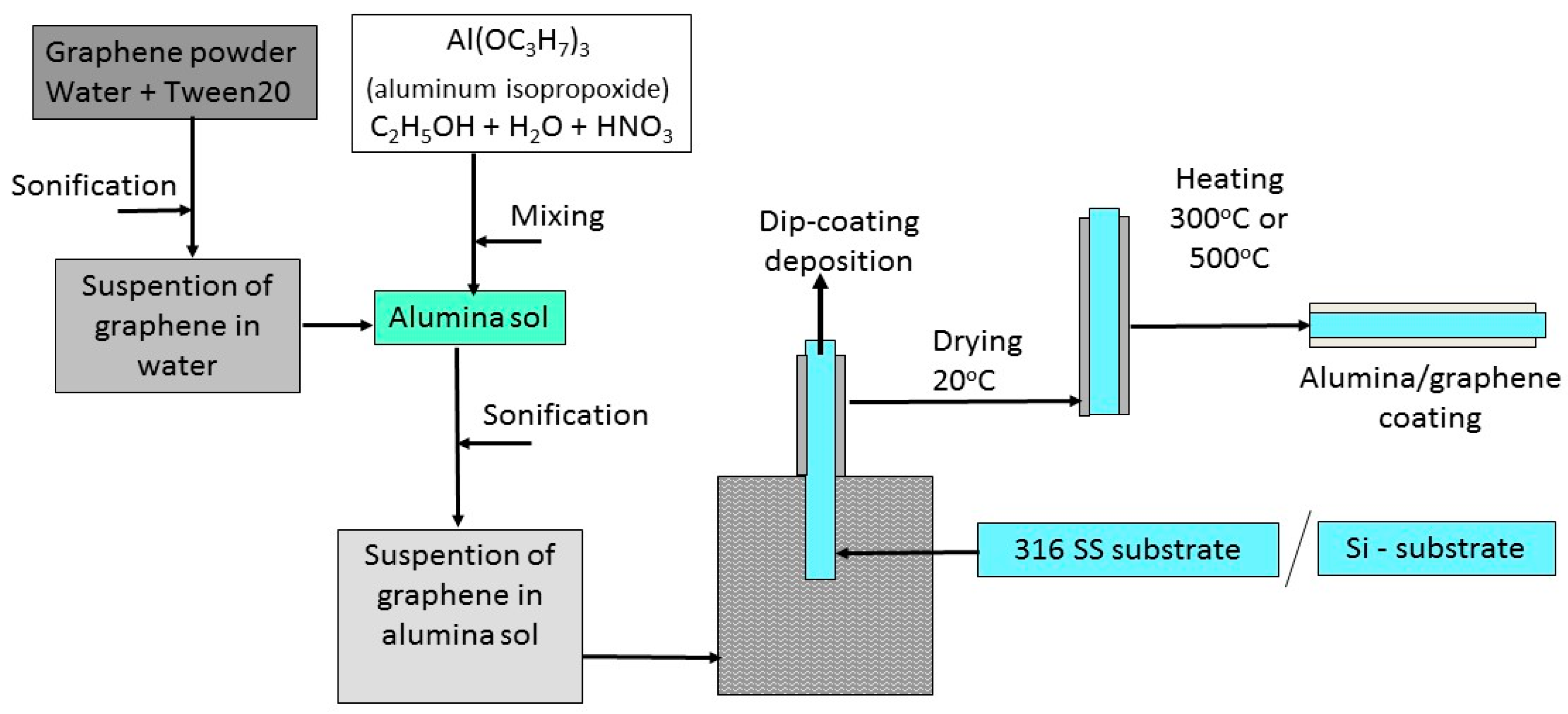
2.1. Deposition of Coatings

Alumina/graphene nanocomposite coatings were manufactured by the sol–gel method using a suspension of reduced graphene oxide (rGO) powder in alumina sol. Aluminum isopropoxide (Sigma-Aldrich, >98%, Steinheim, Germany) was used as a precursor for the preparation of the sol. The precursor was added to water at a temperature higher than 95 °C, acidified with nitric acid. The concentration of precursor in the sol was 0.7 mol/L.
Two kinds of reduced graphene oxide (rGO) in the form of graphene nanoplates (GNPs) were used for preparing composite coatings:
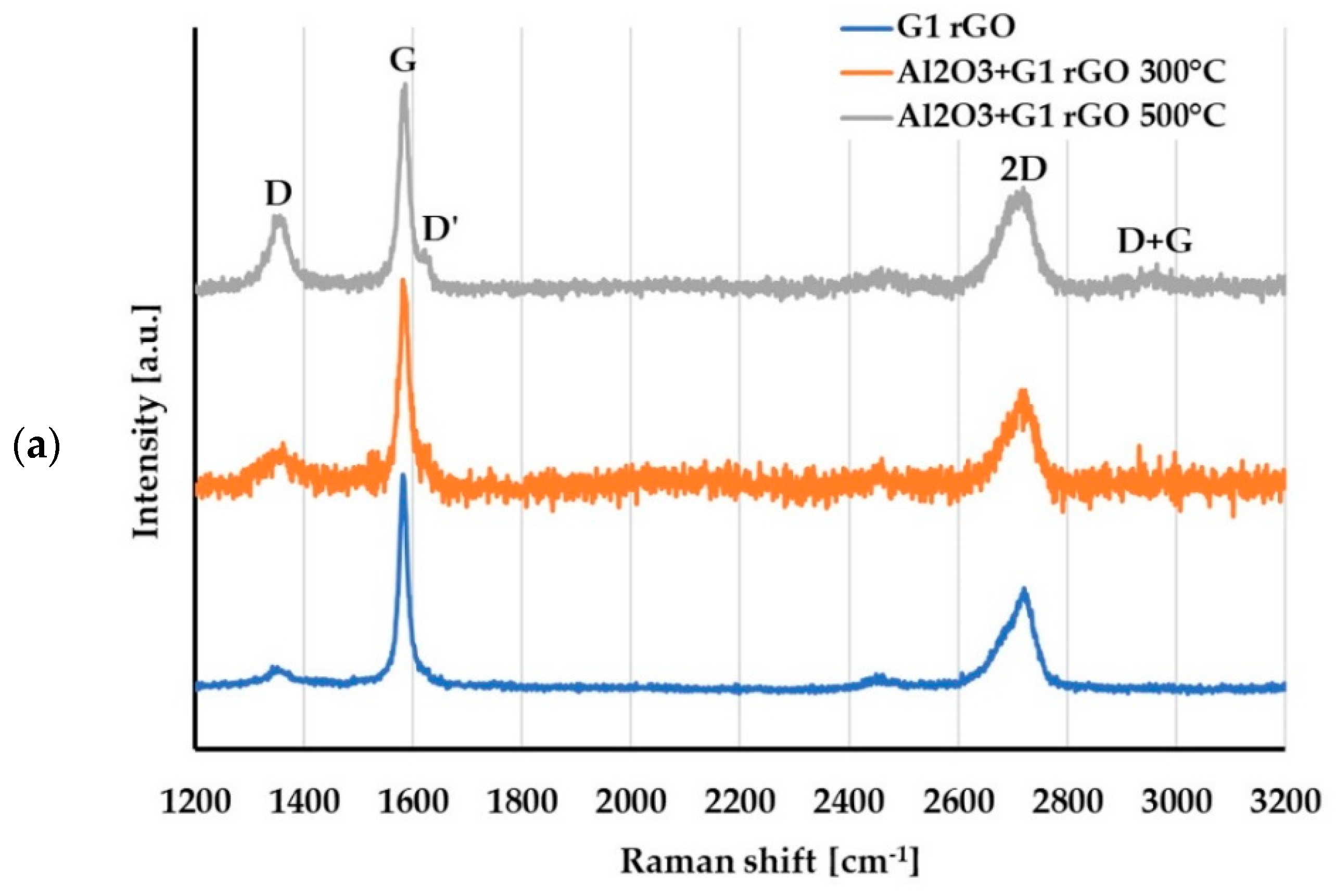
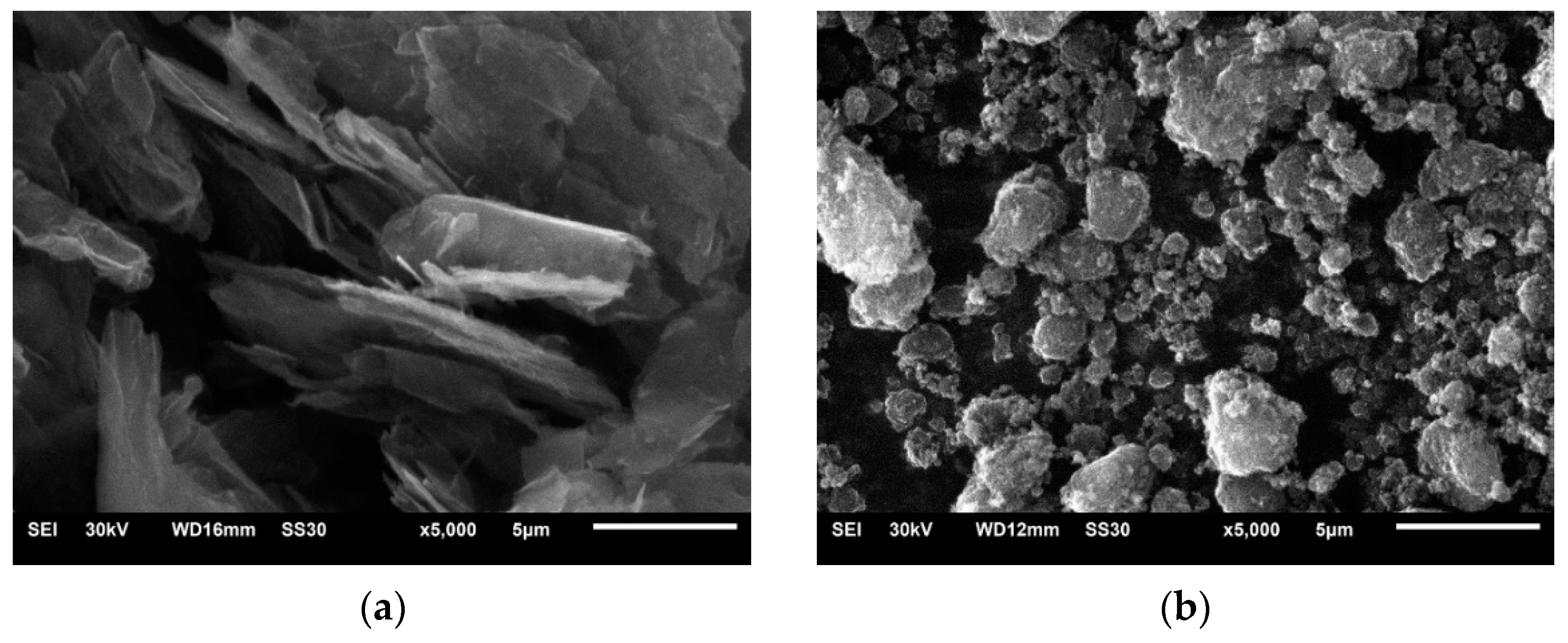
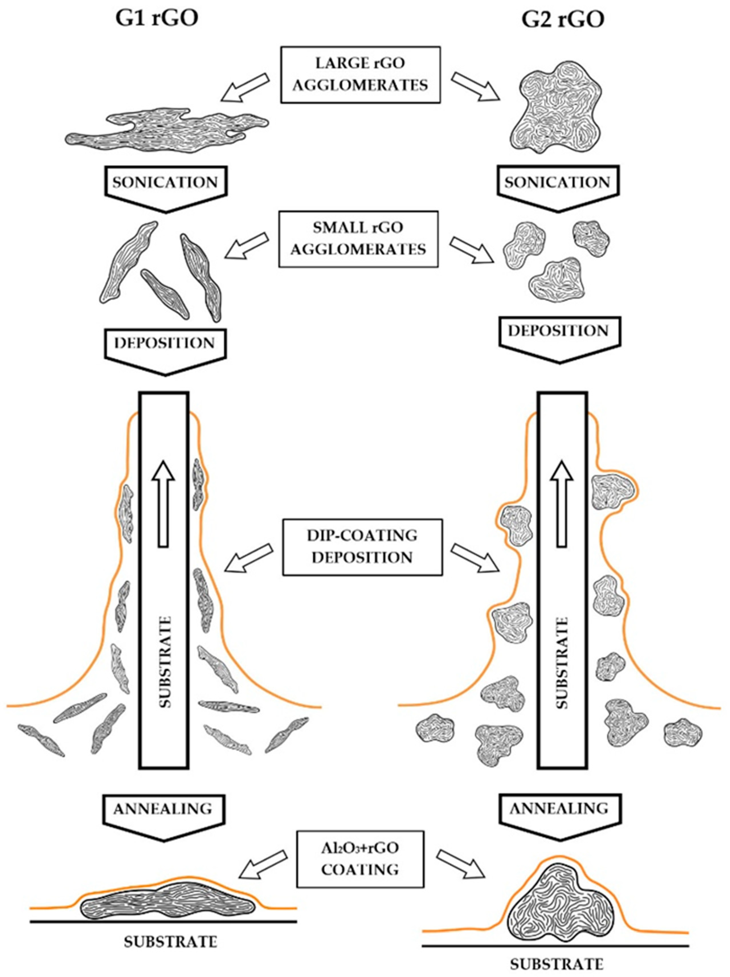
  • G1 rGO (AO-3, Graphene Laboratories Inc., New York City, NY, USA), with an average GNP thickness of 12 nm and an average lateral size 4500 nm;
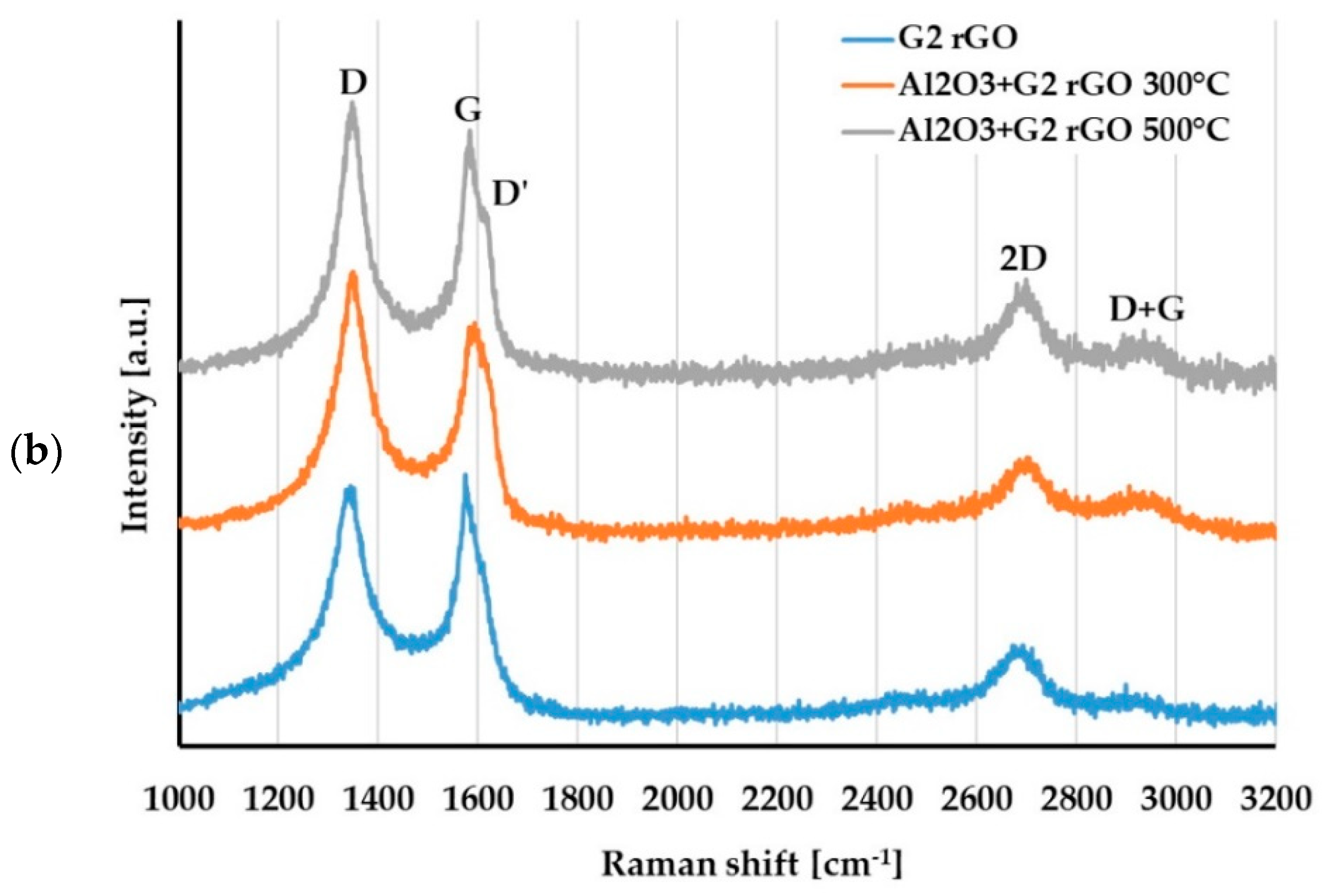
  • G2 rGO (0540DX, SkySpring Nanomaterials, Inc., Houston, TX, USA), with an average GNP thickness of 1–5 nm and an average lateral size of less than 2000 nm.
The suspension of rGO nanoplates in alumina sol was prepared in two stages. In the first step, graphene powder was suspended in water. The appropriate amount of graphene powder was added to 50 mL of water with 0.2 mL of surfactant (Tween 20, Sigma-Aldrich, ≥40%, Steinheim, Germany) to obtain a 4% by weight concentration of graphene. This mixture was sonicated with a Sonics VCX-130 (Sonics, Newtown, CT, USA) sonicator at a frequency of 20 kHz for 8 min divided into 2 min segments. In the next step, the same volumes of the prepared graphene suspension and the alumina sol were mixed and sonicated in the same way for another 8 min. As a result, the Al2O3 + rGO suspension (sol) was obtained. The final concentration of rGO was 2 wt%, and the final concentration of alumina precursor in the Al2O3 + rGO sol was about 0.35 mol/L. For the deposition of Al2O3 coatings without rGO, pure alumina sol was diluted using distilled water to precursor concentration of 0.35 mol/L in order to maintain the same deposition conditions as for the rest of the coatings. For the homogeneity of the suspensions, a 1 min sonication of the Al2O3 + graphene sol was carried out directly before each deposition process.
The Al2O3 and Al2O3 + rGO coatings were deposited on substrates by the dip-coating method. Monocrystalline silicon wafers (100) and discs of 316 stainless steel with a diameter of 12 mm and height of about 5 mm were used as substrates. The surface of the stainless-steel substrates was ground on 800–2000 grade abrasive paper. Before the deposition, substrates (both silicon and stainless steel) were washed in isopropanol for 15 min using an ultrasonic cleaner and dried in compressed air.
The laboratory dip coater, model TLO 0.1 (MTI Corporation, Richmond, CA, USA), was used for the deposition of coatings. The substrates were immersed in prepared suspensions and withdrawn at a controlled constant speed of 120 mm/min. After deposition, coatings were dried at ambient temperature in air for 30 min and annealed in the furnace under air atmosphere at a temperature of 300 °C or 500 °C for 15 min.
The scheme for manufacturing the coatings is shown in Figure 1.

2.2. Characterization of Coatings

The morphology of the prepared coatings deposited on both silicon and stainless steel was investigated using a Hitachi S-3000M scanning electron microscope (SEM) (Hitachi, Tokyo, Japan) working in secondary electron imaging mode.
The surface topography of the coatings deposited on silicon substrates was measured using a multimode atomic force microscope (Bruker Corporation, Billerica, MA, USA) working in tapping mode. Image acquisition was performed using Nanoscope 7.3 software, and further image processing was carried out using Nanoscope Analysis 1.5 software (Bruker Corporation, Billerica, MA, USA). For each sample, a randomly chosen area of about 50 µm × 50 µm was scanned with 512 linear scans (surface profiles). In this area, 3–4 linear scans of the largest agglomerates of graphene nanoplates were additionally performed in order to determine their protruding height relative to the coating surface. For each sample, the topography of the remaining area (RA) not containing the largest agglomerates was also analyzed. The height of protruding particles and agglomerates in these regions (RA) was also determined. Based on the analysis of the topography of the RAs, with sizes of about 20 µm × 20 µm, the commonly used parameters of the surface roughness of coatings, such as Ra and Rmax, were determined.
The structure of both the G1 and G2 rGO powders used for the preparation of the coatings and the structure of the G1 and G2 particles inside the Al2O3 + rGO coatings deposited on the silicon substrates were investigated using a Renishaw inVia Raman spectroscope equipped with a 532 nm laser. The laser power was 0.4 mW. Raman spectra were collected in the range from 1000 cm−1 to 3200 cm−1 for at least 5 points. All measurements were carried out under air atmosphere at room temperature.

3. Results and Discussion
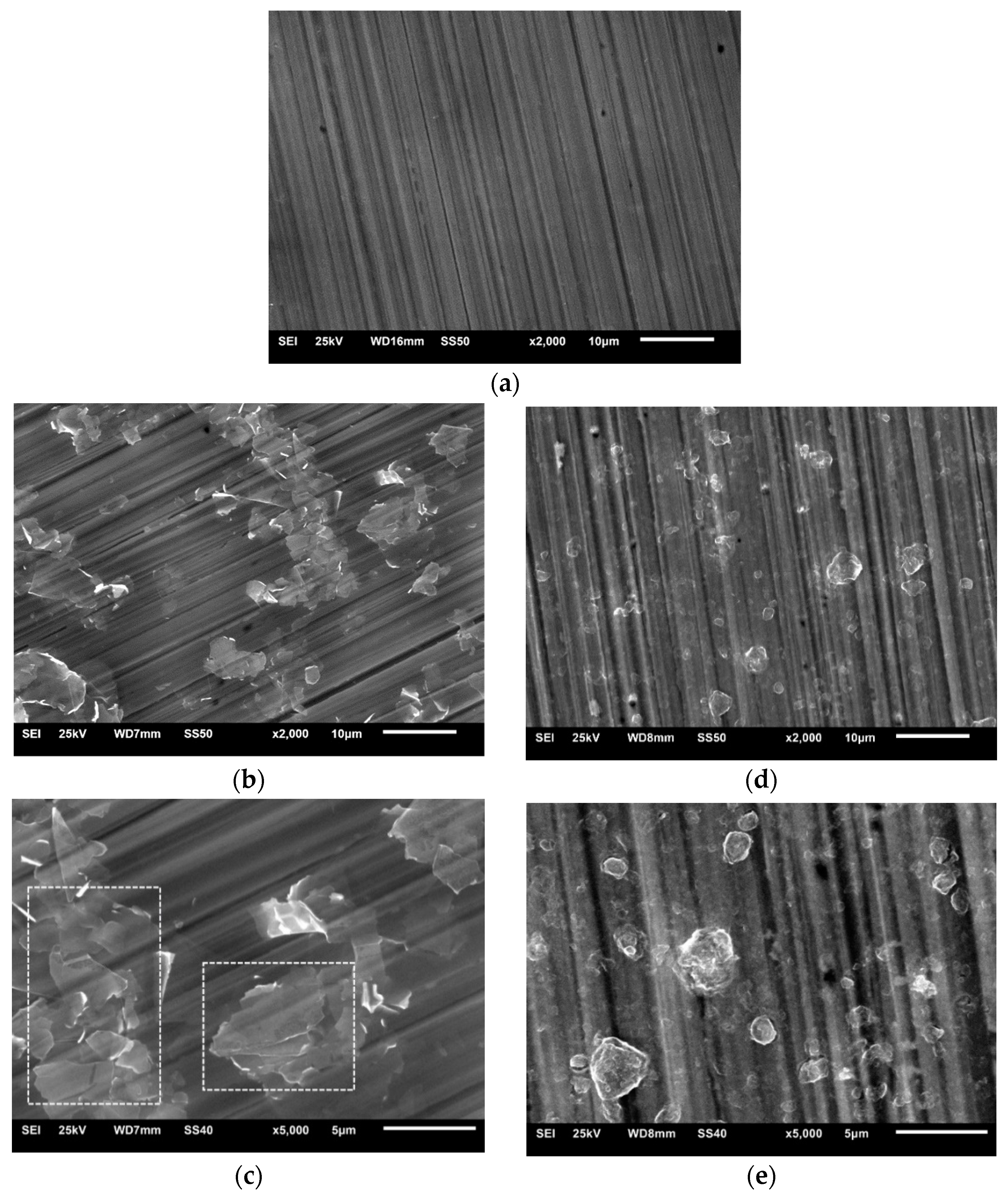
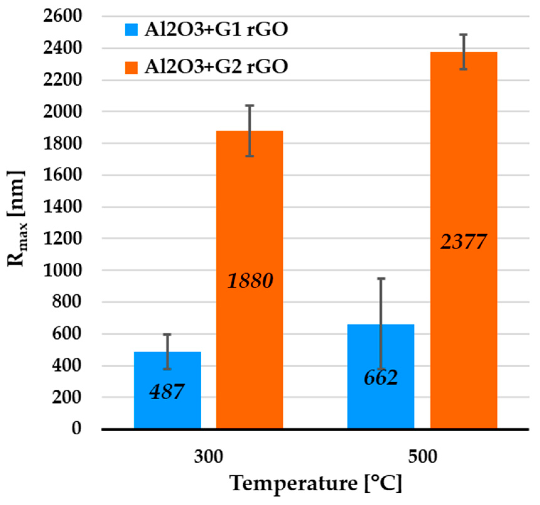
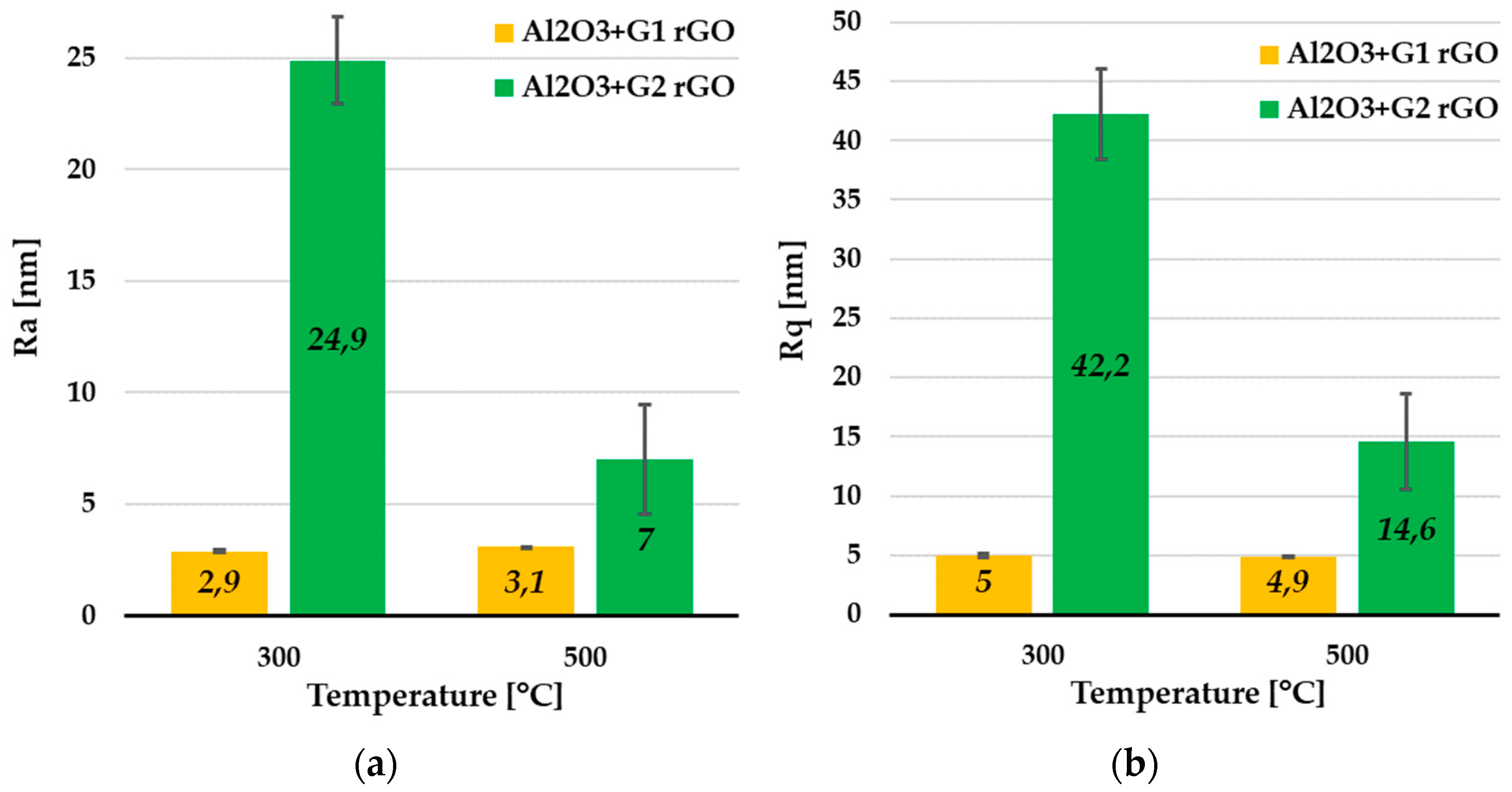
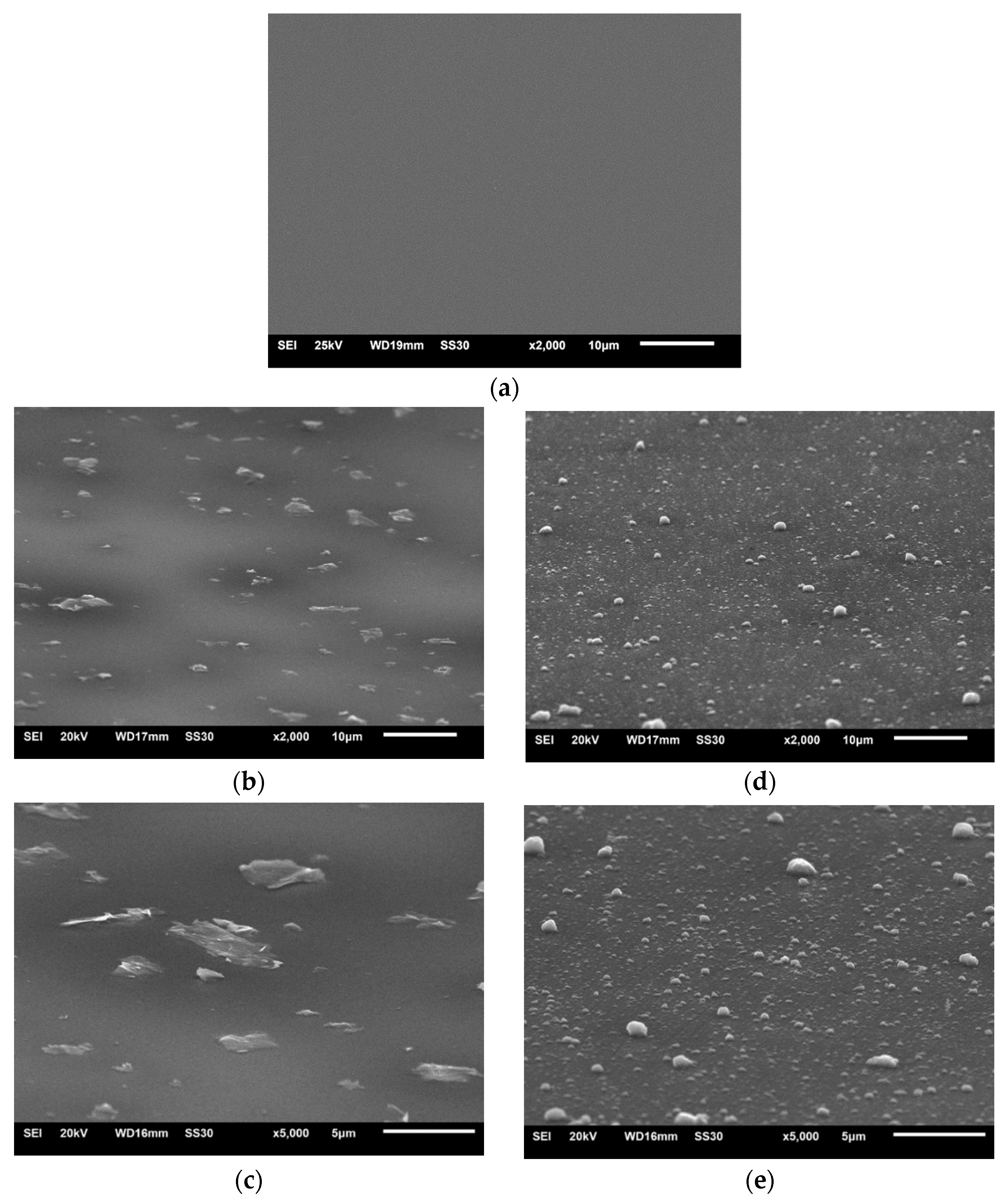
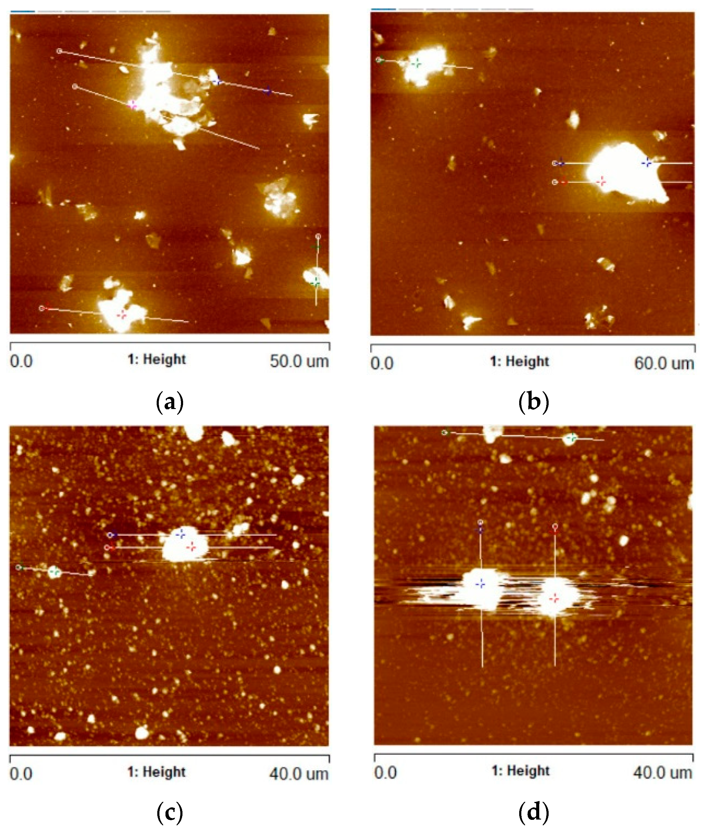
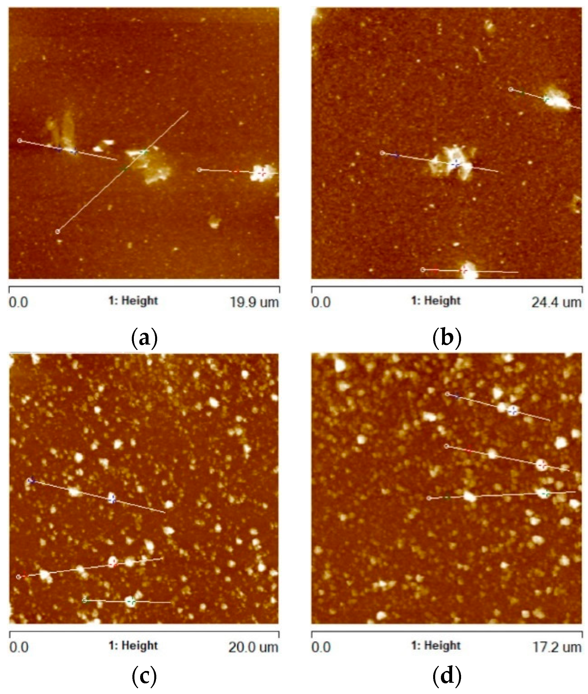
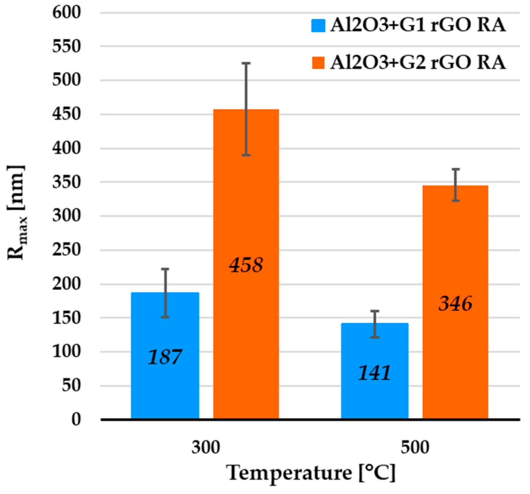
3.1. Morphology

In order to produce the composite coatings, two types of reduced graphene oxide (rGO) powders were used: AO-3, with a larger lateral size, labeled G1; and 0540DX, with a smaller lateral size, labeled G2. Figure 2 shows SEM images of the powders of both types of rGO.
In Figure 2a, it can be observed that the G1 rGO was in the form of stacked nanoplates with lateral sizes from 1 to 10 μm and different thicknesses. Due to the multi-layer arrangement of mutually shifted rGO nanoplates, the lateral sizes of the stacks were larger than the manufacturer claimed (~4500 nm). The G2 rGO powder, shown in Figure 2b, had a different morphology. The powder particles were in the form of spherical agglomerates, the size of which rarely exceeded the dimensions claimed by the manufacturer (~2000 nm). Unlike the G1 rGO, the shape of the G2 rGO agglomerates did not demonstrate an ordered multilayer morphology.
Both types of rGO powder were used to make alumina + rGO colloidal suspensions (sols), which were then used for the deposition of coatings on the substrates using the dip-coating method. SEM images of the surfaces of the Al2O3 coating and the Al2O3 coatings containing G1 rGO and G2 rGO, deposited on Si substrates, are shown in Figure 3.
The surfaces of the coatings deposited on the silicon substrates were free from cracks and discontinuities. Both the G1 and G2 rGO particles were evenly distributed, with shapes similar to the morphologies shown in Figure 2, while their average sizes were significantly smaller. The reduction in the size of the rGO particles in the Al2O3 + G1 and Al2O3 + G2 coatings as compared to the size of the particles in the powders was caused by their ultrasonic dispersion during the preparation of the alumina + rGO suspensions. The SEM images in Figure 2 and Figure 3 show that the ultrasonic dispersion of the graphene particles in the sol did not change their shape but only reduced their size.
Figure 4 shows images of the Al2O3 + rGO coatings deposited on 316 steel substrates. In the case of the Al2O3 + G1 coating (Figure 4b,c), a tendency towards the coagulation of the G1 rGO can be observed. The visible clusters of G1 rGO nanoplates, marked in Figure 4c, clearly indicate their spatial arrangement in a plane parallel to the surface of the substrate, which was also noticeable (although to a lesser extent) in the SEM images of the Al2O3 + G1 coatings produced on silicon substrates (Figure 3b,c). Such an anisotropy of the spatial arrangement was not observed in the SEM images of the Al2O3 + G2 coatings (Figure 3e and Figure 4e).
In both types of Al2O3 + rGO coating, SEM studies revealed a tendency to break up relatively large rGO powder particles into small nanoplates agglomerates of different shapes and arrangements. The G1 rGO agglomerates were in the form of flat nanoplate stacks arranged parallel to the surface of the substrate, while the G2 rGO agglomerates had a more globular shape and their distribution in the coating matrix did not show a clear pattern.
The anisotropic spatial arrangement of rGO nanoplates observed during the SEM research was also analyzed using atomic force microscopy (AFM). In the places where the largest rGO nanoplate agglomerates were found, linear scans (profiles) were conducted, registering the Rmax parameter (the greatest height of unevenness along the measurement line). Example AFM images of these areas are shown in Figure 5, while the collected Rmax data for all variants of the coatings are shown in Figure 6.
The profiles were calculated in order to determine the height of the protruding rGO particles and agglomerates. For the Al2O3 + G1 coatings annealed at 300 °C and 500 °C, the average Rmax values were 487 nm and 662 nm, respectively (Figure 6). In the case of the Al2O3 + G2 coatings, the respective average Rmax values were 1880 nm and 2377 nm. Despite the identical coating deposition parameters, the average Rmax was over 3.5 times higher for the Al2O3 coatings with the addition of G2 rGO.
In addition to the areas containing rGO agglomerates, the surface morphology of the remaining areas of the Al2O3 + G1 and Al2O3 + G2 coatings was also subjected to observation and analysis. Example AFM images of these remaining areas (RAs) of the coatings are shown in Figure 7.
The surface morphology of the two types of alumina + rGO coating differed. In the coatings with the addition of G1 rGO, much larger but relatively few rGO nanoplates could be seen, while in the coatings with the addition of G2 rGO, there were more numerous but smaller nanoplates. The average value of the greatest protrusions (Rmax) was much lower for the Al2O3 + G1 coatings than for the Al2O3 + G2 coatings, showing the same tendency as in the areas containing rGO agglomerates (see Figure 5), but to a lesser extent (Rmax ~2.45 times higher for G2 rGO). The summarized data of the average Rmax values collected for the coatings’ remaining areas (RAs) are shown in Figure 8.
From the coatings’ remaining areas, which were devoid of rGO agglomerates, it was possible to estimate the basic roughness parameters. The average values of the Ra and Rq parameters determined for these areas are summarized in Figure 9.
The average Ra (Figure 9a) and Rq (Figure 9b) roughness parameter values were about 8 times lower for the Al2O3 coatings with G1 rGO addition compared to the Al2O3 + G2 rGO coatings annealed at the same temperature (300 °C). For the same types of coating annealed at 500 °C, these differences were noticeably smaller (about 2.5 times), but the trend was maintained—the roughness of the Al2O3 + G1 coatings was much lower than that of the Al2O3 + G2 coatings. The differences in the roughness parameters of the Al2O3 + G1 and Al2O3 + G2 coatings were therefore similar to the differences observed in the previously analyzed Rmax parameters, for both the areas rich in agglomerates and those without any. Despite the much larger lateral size, the agglomerates of the G1 nanoplates showed much a smaller protruding height (above the surface) compared to the coatings with G2 agglomerates.
The AFM surface geometry analysis confirmed the anisotropic arrangement of rGO in the Al2O3 + G1 coatings, which showed G1 agglomerates with a much lower height protruding above the surface of the coatings and a roughness many times lower compared to the Al2O3 + G2 coatings. This may have been a consequence of the preferred longitudinal arrangement of G1 nanoplates on the surface of the substrates, while the more spherical (equiaxed) G2 agglomerates were arranged more randomly. A proposed scheme for the formation of this arrangement during the dip-coating deposition of the Al2O3 + rGO suspensions is shown in Figure 10. The orderly arrangement of G1 rGO was a consequence of the dip-coating method used to produce the coatings: during the deposition stage, the flat agglomerates of the G1 nanoplates became organized as the substrate was pulled out of the liquid Al2O3 + G1 rGO suspension.
Taking into account the morphology of the G1 rGO powder (Figure 2a), its tendency towards an anisotropic spatial orientation during the dip-coating deposition of the suspension on the substrate may translate onto the tribological properties of the coatings. These properties were previously investigated [15] in terms of the coefficients of friction (COF) and distances to failure on the friction path. Selected results for the obtained COF values and the lengths of the friction paths to the failure/loss of the antifriction properties of the Al2O3 coatings containing 2% rGO and deposited on 316 steel are presented in Table 2.
The average coefficients of friction (COF) and durability of the Al2O3 + G1 coatings were much better than those of the Al2O3 + G2 coatings. Regardless of their annealing temperature, the COFs of the Al2O3 + G1 coatings were in the range of 0.11–0.13 and were maintained over the entire testing distances. On the other hand, significantly higher COFs (0.17 for the coating annealed at 300 °C and 0.51 for the coating annealed at 500 °C) and a lower durability (especially for the coating annealed at 500 °C) were observed in the Al2O3 + G2 coatings, leading to their easier destruction. The comparison of these results with the structural observations and the analysis of the surface geometry allowed us to assign a correlation between the surface morphology of the Al2O3 + rGO coatings and their tribological properties. The Al2O3 + G1 coatings, characterized by the parallel arrangement of rGO nanoplate stacks, a lower Rmax, and a low roughness, consistently showed the best tribological properties in terms of COFs and durability. The Al2O3 + G2 coatings, characterized by the random arrangement of roughly spherical G2 rGO agglomerates, a higher Rmax, and a higher roughness, had far worse antifriction properties and even a tendency towards accelerated failure. The much lower surface roughness of the Al2O3 + G1 coatings as well as the lower height of the protruding G1 rGO stacks (indicated by the Rmax parameter) could substantially contribute to the effective use of the sliding mechanism between graphene nanoplates proposed in our previous work [15] and other studies [11,31]. In addition to the appropriate spatial arrangement of the graphene nanoplates in relation to the substrate and the friction plane, another condition for the optimal use of this mechanism is the maintenance of the parallel arrangement of the nanoplates during sliding, which seems to be possible only on surface areas with a sufficiently high smoothness. After sliding is triggered, the much smoother surfaces of the Al2O3 + G1 coatings are conducive to retaining the parallelism between the moving nanoplates and maintaining the ultra-thin tribofilm, which has been shown to be key for this mechanism [11]. In the case of the Al2O3 + G2 coatings, which are characterized by a much higher roughness and the random spatial arrangement of G2 rGO agglomerates, the activation of the slip mechanism and its continuous maintenance may be largely limited due to the small number of rGO nanoplates arranged parallel to the friction plane and their significant deformation during movement as a consequence of the large irregularities on the rougher surface of the coating. This can lead to the faster depletion of the self-lubricating abilities, a large increase in the coefficient of friction, and progressive intensive wear and failure of the Al2O3 + G2 rGO coating.

3.2. Structure

For the evaluation of changes in the structure of the G1 and G2 rGO powders introduced inside the Al2O3 matrix, Raman spectroscopy was used. The representative spectra of the G1 and G2 rGO powders as well as the Al2O3 + rGO coatings are presented in Figure 11.
The Raman spectrum of graphene contained the characteristic bands G (~1580 cm−1) and 2D (~2700 cm−1), with the G peak representing sp2-hybridized carbon networks and the 2D peak reflecting the number of graphene layers. The I2D/IG ratio can provide information on the layered structure of the GNPs [32,33]. The Raman spectra of the graphene derivatives (GO and rGO) were characterized by additional bands: D (~1350 cm−1), D’ (~1620 cm−1), and D + G (~2940 cm−1) [32,34]. The presence, intensity, and width of these bands depends on the type and number of defects in the graphene structure. As the amount of disorder in the graphene increases, the Raman intensity increases for these three separate disorder peaks: D, D’, and D + G [32]. The parameter indicating the structural disorder of graphene materials is the ID/IG ratio.
A comparison of the Raman spectra in Figure 11a,b reveals that the spectra of the G1 and G2 powders differed, especially in the range of the D and G bands. In the spectrum of the G1 powder, narrow bands with a low ID/IG ratio = 0.1 could be observed, while the spectrum of the G2 powder had wide bands and an ID/IG ratio close to 0.9. This meant that there were more imperfections in the structure of the G2 powder: defects in the carbon lattice as well as functional groups attached to carbon atoms with sp3 hybridization.
For both types of rGO, the Raman spectra of the alumina + rGO coatings showed similar changes compared to the spectra of the G1 and G2 powders. In the spectra of the Al2O3 + rGO coatings, the ID/IG ratio increased (Table 3) as a result of the increase in the intensity of the D band, and the D and D + G bands appeared. These changes indicated an increase in the number of defects in both types of graphene and may have resulted from chemical bonding with the Al2O3 matrix of the coatings as well as the processes of graphene oxidation at the elevated temperature during annealing. The intensity of both the D’ and D + G bands was much greater in the spectra of the Al2O3 + G2 coatings than in those of the Al2O3 + G1 coatings, which proved that there were more imperfections in the G2 rGO structure. A higher number of G2 rGO structure defects may have been the reason for the higher friction coefficient values for the Al2O3 + G2 coatings when compared to the Al2O3 + G1 coatings.
Unlike the other bands, the width and intensity of the 2D band and the I2D/IG ratio differed only slightly between all spectra (Table 3). Therefore, it can be assumed that the number of graphene layers in the rGO nanoplates did not change as a result of the preparation of the graphene suspensions and the production of the coatings. Thus, the fragmentation of the graphene particles visible in the SEM images of the investigated coatings was the result of the destruction of the rGO agglomerates. This fragmentation did not change the structure of the rGO nanoplates, particularly the number of graphene layers in the nanoplates.

4. Summary and Conclusions

Composite coatings consisting of an Al2O3 matrix and the addition of two different types of reduced graphene oxide were successfully produced using the dip-coating sol–gel method. The coatings showed a diversified morphology depending on the type of rGO additive used and its dispersion in the coating matrix.
The coating manufacturing process did not change the original shape of the graphene particles, but only their sizes. The particles were divided into smaller particles by ultrasonic dispersion in the liquid phase, but no “straightening” of the flakes was observed. A similar particle disintegration mechanism may also apply to other 2D materials.
It was found that the dip-coating technique used for the deposition of Al2O3 + rGO coatings from liquid suspensions allows the realization of a favorable morphology due to the ability to spatially arrange the triboactive particles. Differences in the shape and spatial orientation of the rGO agglomerates and the roughness of the Al2O3 + rGO coatings were found to be correlated with their tribological properties. Significantly lower friction coefficients were obtained for coatings containing lamellar nanoplates parallel to the substrate G1 rGO particles. The arrangement of the G1 rGO stacks parallel to the surface of the coatings allowed the use of the slip mechanism between the graphene nanoplates to obtain the lowest friction coefficients. The use of this mechanism in the case of the Al2O3 + G2 coatings was very limited, because the spatial orientation and arrangement of the nanoplates in the G2 rGO agglomerates was probably very chaotic. As a result, these coatings showed significantly worse tribological properties (much higher friction coefficients and poorer durability). This result is an important guideline for the design of low-friction coatings.
In terms of structure, differences in the number of G1 and G2 graphene defects in the coatings and powders were noticed. The number of defects in both types of graphene was noticeably higher when they were contained in the coatings, which may indicate chemical bonding and the oxidation of rGO inside the alumina matrices during the annealing of the coatings. In addition, a greater number of graphene defects were observed in the Al2O3 + G2 coatings compared to those containing G1 graphene. In addition to the varied shapes and spatial arrangements of the rGO agglomerates, the difference in the number of defects may also have contributed to the higher coefficients of friction and worse tribological properties of the coatings containing G2 graphene.

Author Contributions

Conceptualization, S.M. and B.P.; methodology, B.P.; investigation, S.M. and B.P.; writing—original draft preparation, S.M. and B.P.; writing—review and editing, S.M.; visualization, S.M. and B.P. All authors have read and agreed to the published version of the manuscript.

Funding

This research received no external funding.

Institutional Review Board Statement

Not applicable.

Informed Consent Statement

Not applicable.

Data Availability Statement

Data sharing is not applicable to this article.

Acknowledgments

The authors acknowledge Mariusz Dudek for recording Raman spectra and Łukasz Kołodziejczyk for AFM data.

Conflicts of Interest

The authors declare no conflict of interest.

References

  1. Mang, T. (Ed.) Encyclopedia of Lubricants and Lubrication; Springer: Berlin/Heidelberg, Germany, 2014. [Google Scholar]
  2. Erdemir, A. Solid Lubricants and Self-Lubricating Films. In Modern Tribology Handbook; CRC Press LLC: Boca Raton, FL, USA, 2001; Volume 2. [Google Scholar]
  3. Sun, J.; Du, S. Application of Graphene Derivatives and Their Nanocomposites in Tribology and Lubrication: A Review. RSC Adv. 2019, 9, 40642–40661. [Google Scholar] [CrossRef] [PubMed] [Green Version]
  4. Liu, L.; Zhou, M.; Jin, L.; Li, L.; Mo, Y.; Su, G.; Li, X.; Zhu, H.; Tian, Y. Recent Advances in Friction and Lubrication of Graphene and Other 2D Materials: Mechanisms and Applications. Friction 2019, 7, 199–216. [Google Scholar] [CrossRef] [Green Version]
  5. Chouhan, A.; Mungse, H.P.; Khatri, O.P. Surface Chemistry of Graphene and Graphene Oxide: A Versatile Route for Their Dispersion and Tribological Applications. Adv. Colloid Interface Sci. 2020, 283, 102215. [Google Scholar] [CrossRef] [PubMed]
  6. Liu, Y.; Ge, X.; Li, J. Graphene Lubrication. Appl. Mater. Today 2020, 20, 100662. [Google Scholar] [CrossRef]
  7. Kasar, A.K.; Menezes, P.L. Synthesis and Recent Advances in Tribological Applications of Graphene. Int. J. Adv. Manuf. Technol. 2018, 97, 3999–4019. [Google Scholar] [CrossRef]
  8. Srivyas, P.D.; Charoo, M.S. Graphene: An Effective Lubricant for Tribological Applications. In Advances in Engineering Design; Prasad, A., Gupta, S.S., Tyagi, R.K., Eds.; Springer: Singapore, 2019; pp. 239–258. [Google Scholar]
  9. Feng, X.; Kwon, S.; Park, J.Y.; Salmeron, M. Superlubric Sliding of Graphene Nanoflakes on Graphene. ACS Nano 2013, 7, 1718–1724. [Google Scholar] [CrossRef]
  10. Li, J.; Li, J.; Luo, J. Superlubricity of Graphite Sliding against Graphene Nanoflake under Ultrahigh Contact Pressure. Adv. Sci. 2018, 5, 1800810. [Google Scholar] [CrossRef] [PubMed]
  11. Kumar, P.; Wani, M.F. Synthesis and Tribological Properties of Graphene: A Review. J. Tribol. 2017, 13, 36–71. [Google Scholar]
  12. Sarno, M.; Scarpa, D.; Senatore, A.; Ahmed Abdalglil Mustafa, W. RGO/GO Nanosheets in Tribology: From the State of the Art to the Future Prospective. Lubricants 2020, 8, 31. [Google Scholar] [CrossRef] [Green Version]
  13. Paul, G.; Hirani, H.; Kuila, T.; Murmu, N.C. Nanolubricants Dispersed with Graphene and Its Derivatives: An Assessment and Review of the Tribological Performance. Nanoscale 2019, 11, 3458–3483. [Google Scholar] [CrossRef]
  14. Manu, B.R.; Gupta, A.; Jayatissa, A.H. Tribological Properties of 2D Materials and Composites—A Review of Recent Advances. Materials 2021, 14, 1630. [Google Scholar] [CrossRef]
  15. Pietrzyk, B.; Miszczak, S.; Sun, Y.; Szymański, M. Al2O3 + Graphene Low-Friction Composite Coatings Prepared By Sol–Gel Method. Coatings 2020, 10, 858. [Google Scholar] [CrossRef]
  16. Hentour, K.; Turq, V.; Weibel, A.; Ansart, F.; Sobrino, J.-M.; Garcia, J.; Cardey, P.-F.; Laurent, C. Dispersion of Graphite Flakes into Boehmite Sols for the Preparation of Bi-Layer-Graphene/Alumina Coatings on Stainless Steel for Tribological Applications. J. Eur. Ceram. Soc. 2019, 39, 1304–1315. [Google Scholar] [CrossRef] [Green Version]
  17. Zhang, S.A.; Gong, X.F.; Yu, R.P.; Xing, Q.X.; Ling, P.; Wang, Z.X. Self-Lubrication and Wear-Resistance Mechanism of Graphene-Modified Coatings. Ceram. Int. 2020, 46, 15915–15924. [Google Scholar] [CrossRef]
  18. Venturi, F.; Pulsford, J.; Hussain, T. A Novel Approach to Incorporate Graphene Nanoplatelets to Cr2O3 for Low-Wear Coatings. Mater. Lett. 2020, 276, 128283. [Google Scholar] [CrossRef]
  19. Liu, C.; Sun, J.; Venturi, F.; Romero, A.R.; Hussain, T. Microstructure and Wear Performance of Alumina/Graphene Coating on Textured Al2O3/TiC Substrate Composites. J. Eur. Ceram. Soc. 2021, 41, 1438–1451. [Google Scholar] [CrossRef]
  20. Da, B.; Rongli, X.; Yongxin, G.; Yaxuan, L.; Aradhyula, T.V.; Yongwu, Z.; Yongguang, W. Tribological Behavior of Graphene Reinforced Chemically Bonded Ceramic Coatings. Ceram. Int. 2020, 46, 4526–4531. [Google Scholar] [CrossRef]
  21. Li, X.; Shen, Q.; Zhang, Y.; Wang, L.; Nie, C. Wear Behavior of Electrodeposited Nickel/Graphene Composite Coating. Diam. Relat. Mater. 2021, 119, 108589. [Google Scholar] [CrossRef]
  22. Zhang, Y.; Chen, F.; Zhang, Y.; Liu, Z.; Wang, X.; Du, C. Influence of Graphene Oxide on the Antiwear and Antifriction Performance of MAO Coating Fabricated on MgLi Alloy. Surf. Coat. Technol. 2019, 364, 144–156. [Google Scholar] [CrossRef]
  23. Mai, Y.J.; Zhou, M.P.; Ling, H.J.; Chen, F.X.; Lian, W.Q.; Jie, X.H. Surfactant-Free Electrodeposition of Reduced Graphene Oxide/Copper Composite Coatings with Enhanced Wear Resistance. Appl. Surf. Sci. 2018, 433, 232–239. [Google Scholar] [CrossRef]
  24. Shen, G.; Zhang, L.; Gu, Z.; Zheng, Z.; Liu, Y.; Tan, G.; Jie, X. Zinc Aluminum-Layered Double Hydroxide(LDH)-Graphene Oxide(GO) Lubricating and Corrosion-Resistant Composite Coating on the Surface of Magnesium Alloy. Surf. Coat. Technol. 2022, 437, 128354. [Google Scholar] [CrossRef]
  25. Zhang, R.; Yu, X.; Yang, Q.; Cui, G.; Li, Z. The Role of Graphene in Anti-Corrosion Coatings: A Review. Constr. Build. Mater. 2021, 294, 123613. [Google Scholar] [CrossRef]
  26. Ding, J.; Zhao, H.; Yu, H. Superior and Durable Graphene-Based Composite Coatings by Bioinspired Interfaces and Alignment. Compos. Sci. Technol. 2021, 214, 108967. [Google Scholar] [CrossRef]
  27. Qin, W.; Ma, J.; Liang, Q.; Li, J.; Tang, B. Tribological, Cytotoxicity and Antibacterial Properties of Graphene Oxide/Carbon Fibers/Polyetheretherketone Composite Coatings on Ti–6Al–4V Alloy as Orthopedic/Dental Implants. J. Mech. Behav. Biomed. Mater. 2021, 122, 104659. [Google Scholar] [CrossRef] [PubMed]
  28. Han, W.; Wu, Z.; Li, Y.; Wang, Y. Graphene Family Nanomaterials (GFNs)—Promising Materials for Antimicrobial Coating and Film: A Review. Chem. Eng. J. 2019, 358, 1022–1037. [Google Scholar] [CrossRef]
  29. Berman, D.; Erdemir, A.; Sumant, A.V. Few Layer Graphene to Reduce Wear and Friction on Sliding Steel Surfaces. Carbon 2013, 54, 454–459. [Google Scholar] [CrossRef]
  30. Liang, H.; Bu, Y.; Zhang, J. Graphene Oxide Film as Solid Lubricant. ACS Appl. Mater. Interfaces 2013, 5, 6369–6375. [Google Scholar] [CrossRef]
  31. Cheng, Z.; Andy, N.; Arvind, A. Ultrathin Graphene Tribofilm Formation during Wear of Al2O3–Graphene Composites. Nanomater. Energy 2016, 5, 1–9. [Google Scholar]
  32. Childres, I.; Jauregui, L.A.; Park, W.; Cao, H.; Chen, Y.P. Raman Spectroscopy of Graphene and Related Materials. In New Developments in Photon and Materials Research; Physics Research and Technology; Nova Science Publishers: New York, NY, USA, 2013; Volume 1, pp. 403–418. ISBN 978-1-62618-339-1. [Google Scholar]
  33. Gupta, A.; Chen, G.; Joshi, P.; Tadigadapa, S.; Eklund, P.C. Raman Scattering from High-Frequency Phonons in Supported n-Graphene Layer Films. Nano Lett. 2006, 6, 2667–2673. [Google Scholar] [CrossRef] [Green Version]
  34. Zhao, J.; Lizhao, L.; Fen, L. Graphene Oxide: Physics and Applications; Springer Briefs in Physics; Springer Heidelberg: New York, NY, USA, 2015; ISBN 978-3-662-44829-8. [Google Scholar]
Figure 1. The scheme for manufacturing Al2O3 + rGO coatings.
Coatings 12 01153 g001
Figure 2. SEM images of both types of rGO powder: (a) G1 and (b) G2. Magnification 5000×.
Coatings 12 01153 g002
Figure 3. SEM images of Al2O3 composite coatings deposited on Si substrates: (a) pure Al2O3; (b,c) Al2O3 + G1 rGO; (d,e) Al2O3 + G2 rGO. Magnifications 2000× and 5000×.
Coatings 12 01153 g003
Figure 4. SEM images of Al2O3 composite coatings deposited on steel substrates: (a) pure Al2O3; (b,c) Al2O3 + G1 rGO; (d,e) Al2O3 + G2 rGO. Magnifications 2000× and 5000×. Flat graphene flakes parallel to the substrate are highlighted in Figure 4c.
Coatings 12 01153 g004
Figure 5. AFM images of Al2O3 coatings containing (a) G1 rGO powder (annealed at 300 °C), (b) G1 rGO powder (annealed at 500 °C), (c) G2 rGO powder (annealed at 300 °C), (d) G2 rGO powder (annealed at 500 °C). All coatings were deposited on Si substrates.
Coatings 12 01153 g005
Figure 6. Average Rmax values collected from AFM profiles of rGO agglomerate areas of Al2O3 coatings containing G1 rGO and G2 rGO, annealed at 300 °C and 500 °C. Coatings were deposited on Si substrates.
Coatings 12 01153 g006
Figure 7. AFM images of Al2O3 coating remaining areas (RAs) containing (a) G1 rGO powder (annealed at 300 °C), (b) G1 rGO powder (annealed at 500 °C), (c) G2 rGO powder (annealed at 300 °C), (d) G2 rGO powder (annealed at 500 °C). All coatings were deposited on Si substrates.
Coatings 12 01153 g007
Figure 8. Average Rmax values from AFM profiles collected for remaining areas (RAs) of Al2O3 coatings containing G1 rGO and G2 rGO, annealed at 300 °C and 500 °C. Coatings were deposited on Si substrates.
Coatings 12 01153 g008
Figure 9. Average Ra (a) and Rq (b) values collected from remaining areas (RAs) of Al2O3 coatings containing G1 rGO and G2 rGO, annealed at 300 °C and 500 °C. Coatings were deposited on Si substrates.
Coatings 12 01153 g009
Figure 10. Schematic representation of the formation of G1 and G2 rGO nanoplate agglomerate arrangement during dip-coating deposition. Sizes of agglomerates not to scale.
Coatings 12 01153 g010
Figure 11. Raman spectra of: (a) G1 rGO powder and Al2O3 + G1 rGO coatings annealed at 300 °C and 500 °C; (b) G2 rGO powder and Al2O3 + G2 rGO coatings annealed at 300 °C and 500 °C.
Coatings 12 01153 g011aCoatings 12 01153 g011b
Table 1. Average coefficients of friction (COF) and testing distances of various composite coatings containing graphene [15,16,17,18,19,20,21,22,23,24].
Type of CoatingSubstrateDeposition MethodAverage COFTesting Distance (m)
Al2O3 + rGO [15]316 steelSol–gel dip coating0.11>100
Al2O3 + GNP [16]304L steelSol–gel dip coating0.14>250
WC-Co + GO [17]316 steelPlasma spraying0.30-
Cr2O3 + GNP [18]304 steelThermal spraying0.51>67
Al2O3 + GNP [19]Al2O3/TiCThermal spraying0.38>35
Al2O3/ZnO/AP + GNP [20]A3 steelAerosol spraying0.37-
Ni + EGNP [21]304 steelElectrodeposition0.16>150
MgO/SiO + GO [22]Mg-Li alloyMicro-arc oxidation0.15>63
Cu + rGO [23]Cu-Zn alloyElectrodeposition0.25>63
ZnAl-LDH + GO [24]Mg-Al-Zn alloyCold spraying/electrostatic deposition0.20>75
Table 2. Average coefficients of friction (COF) and distances to failure/loss of antifriction properties of Al2O3 and Al2O3 + 2%rGO coatings deposited on 316 steel [15].
Type of CoatingAnnealing Temperature (°C)Average COFDistance to Failure (m)
Uncoated steel substrate-0.88 ± 0.005-
Al2O33000.87 ± 0.086~18
5000.77 ± 0.078~27
Al2O3 + G1 rGO3000.13 ± 0.004>100
5000.11 ± 0.006>100
Al2O3 + G2 rGO3000.17 ± 0.005>100
5000.51 ± 0.22~65
Table 3. ID/IG and I2D/IG ratios determined from Raman spectra of rGO powders and Al2O3 + rGO coatings annealed at 300 °C and 500 °C.
Type of Powder/CoatingAnnealing Temperature (°C)ID/IGI2D/IG
G1 rGO powder0.10 ± 0.080.36 ± 0.06
Al2O3 + G1 rGO3000.22 ± 0.120.38 ± 0.09
Al2O3 + G1 rGO5000.24 ± 0.110.39 ± 0.08
G2 rGO powder0.90 ± 0.050.34 ± 0.04
Al2O3 + G2 rGO3001.26 ± 0.090.37 ± 0.12
Al2O3 + G2 rGO5001.17 ± 0.100.35 ± 0.08
Publisher’s Note: MDPI stays neutral with regard to jurisdictional claims in published maps and institutional affiliations.

