Article

Design and Analysis of Biomedical Scaffolds Using TPMS-Based Porous Structures Inspired from Additive Manufacturing

1
Biomechanics Lab, School of Biomedical Engineering, Indian Institute of Technology (BHU), Varanasi 221005, India
2
Department of Biomedical Engineering, National Institute of Technology, Raipur 492010, India
3
Department of Mechanical Engineering, GLA University, Mathura 281406, India
4
State Key Laboratory of Mechanical System and Vibration, School of Mechanical Engineering, Shanghai Jiao Tong University, Shanghai 200240, China
*
Authors to whom correspondence should be addressed.
Coatings 2022, 12(6), 839; https://doi.org/10.3390/coatings12060839
Submission received: 29 April 2022 / Revised: 10 June 2022 / Accepted: 12 June 2022 / Published: 15 June 2022

Abstract

:
Gyroid (G) and primitive (P) porous structures have multiple application areas, ranging from thermal to mechanical, and fall in the complex triply periodic minimal surface (TPMS) category. Such intricate bioinspired constructs are gaining attention because they meet both biological and mechanical requirements for osseous reconstruction. The study aimed to develop G and P structures with varying porosity levels from 40% to 80% by modulating the strut thickness to proportionally resemble the stiffness of host tissue. The performance characteristics were evaluated using Ti6Al4V and important relationships between feature dimension, strut thickness, porosity, and stiffness were established. Numerical results showed that the studied porous structures could decrease stiffness from 107 GPa (stiffness of Ti6Al4V) to the range between 4.21 GPa to 29.63 GPa of varying porosities, which matches the human bone stiffness range. Furthermore, using this foundation, a subject-specific scaffold (made of P unit cells with an 80% porosity) was developed to reconstruct segmental bone defect (SBD) of the human femur, demonstrating a significant decrease in the stress shielding effect. Stress transfer on the bone surrounded by a P scaffold was compared with a solid implant which showed a net increase of stress transfer of 76% with the use of P scaffold. In the conclusion, future concerns and recommendations are suggested.

1. Introduction

A segmental bone defect (SBD) caused by tumor, trauma, or osteoarthritis is presently an exigent and expensive issue in the orthopedic field. Segmental bone defects are characterized as defects that do not repair on their own and are commonly classified as gaps greater than double the thickness of the long bone diaphysis [1]. In most conditions of trauma or excision owing to malignant, diseased, or defective bone tissue, SBD presents a significant reconstruction challenge [2,3,4]. Possible alternatives for reconstruction surgery of SBD consist of bone grafts (autografts, allografts, and xenografts), intercalary endoprostheses (segmental prostheses), segmental transport, and cemented bone spacers [5,6,7,8]. The segmental bone prosthesis technique is preferred due to the benefits of early stability, rapid weight-bearing, and faster recovery [9,10], despite concerns, such as aseptic loosening, periprosthetic fracture, and low survival rates, particularly in generally young patients [11,12]. Therefore, segmental defects must be repaired with a scaffold sustaining effective load-bearing capability, while also enhancing a healing process at the defect site, resulting in a sustainable bone-implant interface with spontaneous regeneration.
Three-dimensional porous scaffolds are a versatile solution for SBD as they can be used for osseous reconstruction to reinstate the functionality of bone. Due to their lightweight construction, appropriate load-bearing capability, permeability to essential body fluids, improved bone integrity, and ability to regenerate bone throughout the implant, porous scaffolds are preferred over conventional solid implants [8,13,14,15,16]. However, TPMS-based scaffolds have emerged to be an ideal candidate for the reconstruction of segmental defects, because of their biomorphic and bio-mimicking properties [17,18,19,20,21]. To improve the integrity of the bone-implant interface, these TPMS-based porous scaffolds offer essential support and assist in cell adhesion, proliferation, and differentiation. This increases biomechanical compatibility and durability, while significantly reducing the risk of bone resorption caused by the stress shielding effect. Both numerical and experimental analyses of the TPMS scaffolds are presented extensively in the literature that illustrates their multifunctional behavior [22,23,24,25].
Human bone tissue is classified into two main categories: the outer cortical (compact) bone and the extremely porous and spongy inner trabecular (cancellous) bone. Cortical bone generally has an elastic modulus of 15–19 GPa, volume fractions of 0.5–0.95, and size of pore ranging from 50–110 μm, whereas cancellous bone has Young’s modulus of 0.5–5 GPa, volume fractions in the range of 0.05–0.4, and pore diameters of 550–1500 μm [26,27,28]. The morphological characteristics and complexity of human bone are efficiently mimicked by TPMS-based bone scaffolds.
TPMS maintain a mean curvature that remains zero at each point and is comparable to the mean curvature of trabecular bone [29,30]. They are perfect for osseous restoration because they have a porous structure that is smooth and continuous, having no jagged corners or edges, and divide the area into two or more interconnected, non-superimposed, infinite regions that can be replicated over three perpendicular directions [31,32,33,34]. These are nature-inspired materials that are found to exist naturally in soap films and butterfly wings (Cyanophrys, specifically Teinopalpus imperialis and Parides sesostris) that consist of many differently orientated, 3D single G geometrical structures [35,36,37,38]. Schwarz P and Diamond (D), Schoen’s G, Schoen’s I-WP, Neovius, the Fischer–Koch S, and F-RD are a family of TPMS that are commonly used to develop lightweight models for a variety of applications [39,40,41]. Among all the members of the TPMS family, the P surface and G surface have been widely used in the application of osseous reconstruction [42,43,44]. Schwarz P surface has the maximum pore size, due to its pore shape, and allows the highest fluid permeability compared to other members of the TPMS family. It possesses a high porosity which allows cells to diffuse and proliferate well and, hence, Schwarz P scaffolds are considered to have the highest structural stability [45,46,47,48]. Schoen’s G surfaces have proved to provide high specific strength [22,49,50,51] and present excellent load-bearing capacity, making them appropriate for reconstruction of bone defects [20,52].
To construct bone-mimicking scaffolds with better bone regeneration ability, control over porosity, pore size, surface area, and permeability, as well as manipulation of strength and stiffness, are essential. Optimization of pore size and porosity has been the major concern of researchers, as it directly affects osseous regeneration [53,54,55,56]. Porosity can be varied by altering the thickness of the surface or struts, such that they are suitable for trabecular or cortical bone replacement (50%–90% porosity) [57,58]. Also, porosity and volume fraction influence the bone density and vary according to the anatomical location of the bone. Hence, it is essential to consider these variations while designing the scaffold for a particular site [59,60,61]. The pore shape (type of TPMS), unit cell size, and porosity collectively control the pore size of a TPMS scaffold structure [56,62].
To efficiently minimize the stress shielding, the scaffold design should concentrate on the site-specific anatomical variations in stiffness. As compared to standard solid implants, the use of porous scaffolds can significantly reduce the stress shielding effect [20,63,64]. By minimizing the difference between implant stiffness to that of bone, implant stability and durability improve [65,66,67]. Therefore, porosity plays an essential role in reducing Young’s modulus, and the stress shielding effect can be reduced to a significant level [68,69,70].
Moreover, orthopedic surgeons continue to face difficulties in repairing significant bone abnormalities. Therefore, the main objective to produce a subject-specific SBD scaffold with intricate patterns and structures may be accomplished by using the simplest possible design and advanced manufacturing techniques. TPMS-based porous scaffolds can, therefore, be modeled using a mathematical or manual computer-aided design (CAD) approach and the fabrication of these complex models by advanced 3-D printing techniques ensures dimensional accuracy, precisely lower defect rate, and improved mechanical characteristics [71]. Among a vast range of available biocompatible metals, titanium and its alloys (Ti6Al4V) are considered to be best for additive manufacturing (selective laser sintering (SLS), selective laser melting (SLM), electron beam melting (EBM)) of bone implants with enhanced corrosion resistance properties [65,72,73].
For treating large SBD, TPMS-based porous scaffolds are designed and mapped on the solid bone model using Boolean operations, resulting in a porous scaffold structure, ensuring application at various anatomical sites for bridging bone gaps [74,75,76,77]. The bone mapping method is patient-specific, and the customized modeling methodology demonstrates the efficacy of the design criterion to develop a proficient bone scaffold architecture for generating patient-specific implants with adequate mechanical characteristics [74,78,79,80].
This paper focuses on the evaluation of mechanical properties of sheet G- and P-based open-pore lattices developed from a biocompatible Ti6Al4V alloy with varying relative densities. G and P samples were developed using a CAD-based modeling technique and analyzed by using the finite element method to evaluate the stiffness and strength of the lattices. The reduction of stress shielding effect on bone was demonstrated by developing and analyzing an SBD scaffold based on the above P lattice structures.

2. Materials and Methods

2.1. Mathematical Description and Generation of TPMS Unit Cells

Methodologies, such as the image-based method [21,81], implicit function-based surface generation [82,83], space fitting curve [84], and CAD-based approach [85,86,87,88], are used to construct TPMS-based structures. In this work, implicit function-based surface generation was employed to generate P and G surfaces.
TPMS is expressed by using Enneper-Weierstrass representation parametrically, in which nodal coordinates of the TPMS analytical surface may be calculated by computing the integral function of the Weierstrass equation [89]. They are represented by the Equations (1)–(3) as follows:
x = Re   ( e i θ ω o ω ( 1 τ 2 )   R ( τ )   d τ )
y = Re   ( e i θ ω o ω i ( 1 + τ 2 )   R ( τ )   d τ )
z = Re   ( e i θ ω o ω   2 τ R ( τ )   d τ )
where; i2 = −1, θ is the bonnet angle, τ represents a complex variable (τ = τa + iτb), R(τ) represents the Weierstauss function, which changes depending on the surface. For the P and G TPMS structures, R(τ) can be formulated as Equation (4):
R   ( τ ) = 1 1 + λ τ 4 + τ 8  
where λ = −14. The associated TPMS architecture can be obtained by varying the bonnet angle (θ). For P surface, θ = π/2 (90°), and for G surface, θ = 38.0147°.
Compared with the above parametrized TPMS, the P and G surfaces can be generated by combining trigonometric functions with implicit functions of the first order of approximation, as expressed in Equations (5) and (6) [90].
  • P surface (Schwarz P);
ϕ   ( x ,   y ,   z ) = cos ( ω x x ) + cos ( ω y y ) + cos ( ω z z ) = c
  • G surface (Schoen’s G);
ϕ   ( x ,   y ,   z ) = sin ( ω z z ) cos ( ω y y ) + sin ( ω z z ) cos ( ω x x ) + sin ( ω y y ) cos ( ω z z ) = c
where ωx, ωy, ωz is the periodicity of P and G expressions and can also be expressed as Equation (7):
ω i = 2 π n i l i   ( Where ,   i   = x ,   y ,   z )
where, ni is the number of cell repetitions in x, y, z coordinates, li represents the absolute sizes in those directions, and c denotes the ISO value (the level set constant) that determines a specific surface with geometry comparable to that of a minimal surface. If the value of c is zero, the obtained minimal surface divides the region into sub-regions of equal volume. The thickness varies as the magnitude of level constant (c) is increased or decreased. Therefore, this is an essential parameter used as a control constraint.
We triangulated the parametric surface of P and G by using the marching cubes (MC) algorithm, which directly calculates the coordinates of the point in a 3D data field on the surface, using a previously determined level constant (c) [91]. The intersecting points, as well as hexahedral sides of the iso-surface, are linked together specifically in the MC approach, and the resulting iso-surface has been approximated such that it reveals the implicit surface. Therefore, using the trigonometric equation and MC algorithm, two TPMS surface unit cells of 1 × 1 × 1 mm3 were rendered and conveniently converted in stereolithographic (STL) format by the STLWRITE command in MATLAB, which contains information about the triangular surface of a particular TPMS. Two distinct P and G open and closed surfaces are visualized in Figure 1.

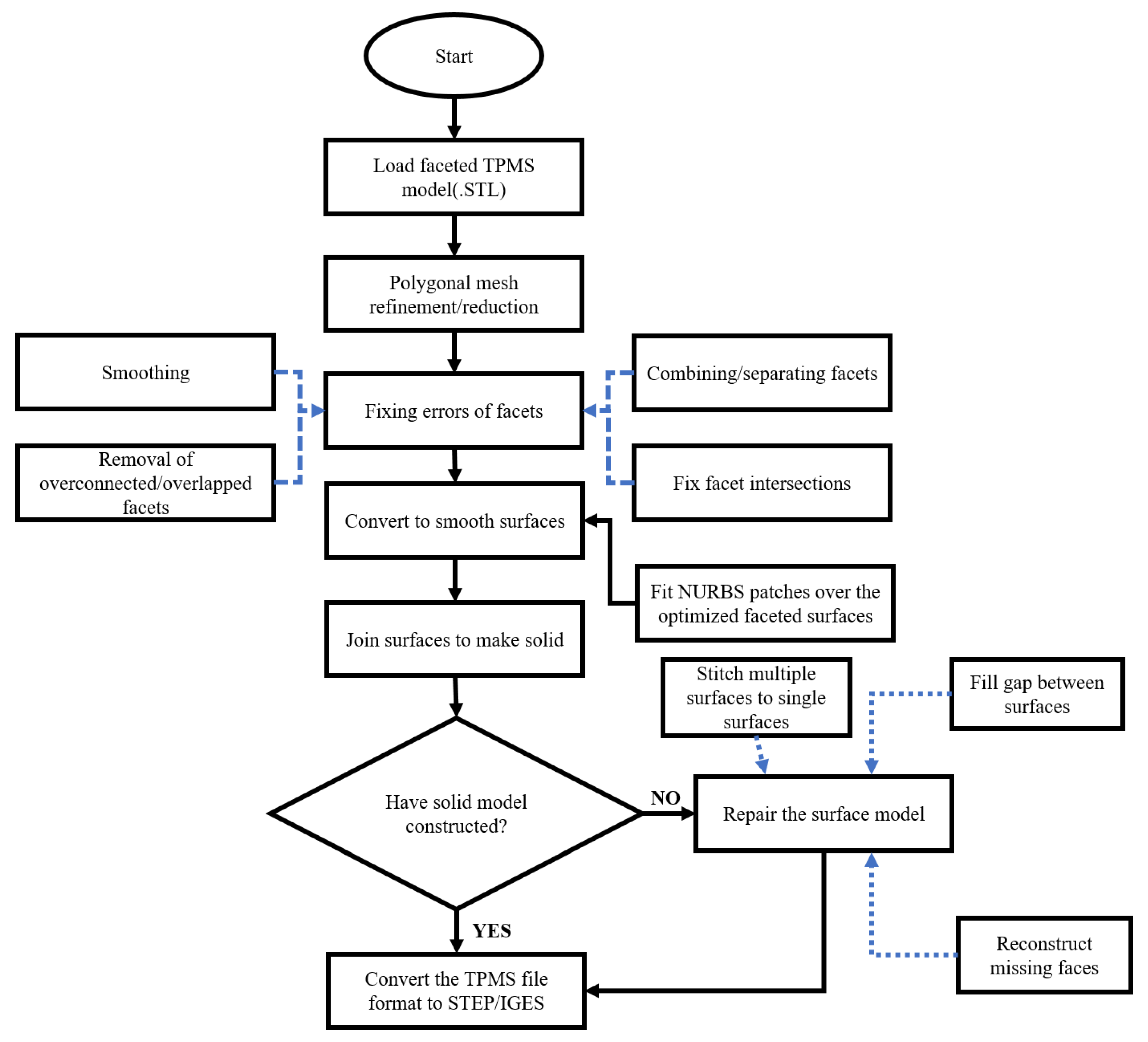
2.2. STL to Solid Multiscale Design Conversion Protocol of TPMS

Since STL models are tessellated triangular (faceted) meshes that employ points and edges to construct spatial triangles to approximate the 3D surface (entirely hollow inside) and cannot be modified, they are not suitable for finite element analysis (FEA), as they do not have any CAD model attributes, such as virtual solid volume. However, due to the fundamental difference between surface mesh and 3D finite element mesh, STL mesh data cannot be directly utilized in FEA. It is necessary to transform the STL into a solid body that preserves the overall surface and volume data information to employ 3D elements, such as tetrahedral or hexahedral elements. In light of these issues, an efficient method for converting STL to a solid body was proposed and used with outstanding defeaturing, repair and cleanup capabilities, which is shown by a flow diagram in Figure 2.

2.3. Generating Large TPMS Structures as Lattices

To evaluate the biomechanical responses of TPMS structure-based lattice, such as compressive strength and elastic modulus, we generated five volume fractions (Vf) of 20%, 30%, 40%, 50% and 60% corresponding to porosity (p) of 80%, 70%, 60%, 50% and 40%, respectively, of TPMS model (P and G), by using the methods described in the above Section 2.1 and Section 2.2. As shown in the first and third rows of Figure 3, a total of ten models of the representative unit cell of corresponding structures were constructed and patterned along the x, y, and z axes of the global Cartesian coordinate system to generate the 2 × 2 × 2 mm3 lattice structure shown in the second and fourth rows of Figure 3. By altering the thickness (t) from 0.085 mm to 0.256 mm for the P surface and 0.0644 mm to 0.193 mm for the G surface, a library of scaffolds, with different volume fractions (Vf) ranging from 20% to 60%, was created. Figure 3 clearly shows that increasing the strut thickness increased the scaffold volume and, conversely, decreased the porosity (p) of the lattice from 80% to 40%, respectively, as represented by arrow lines. The following Equation (8) was used to calculate the porosity of a given scaffold [53]:
Porosity   ( p ) = 1   ( V P V S )
where VP is the volume of scaffold material and Vs is the total volume of the scaffold.

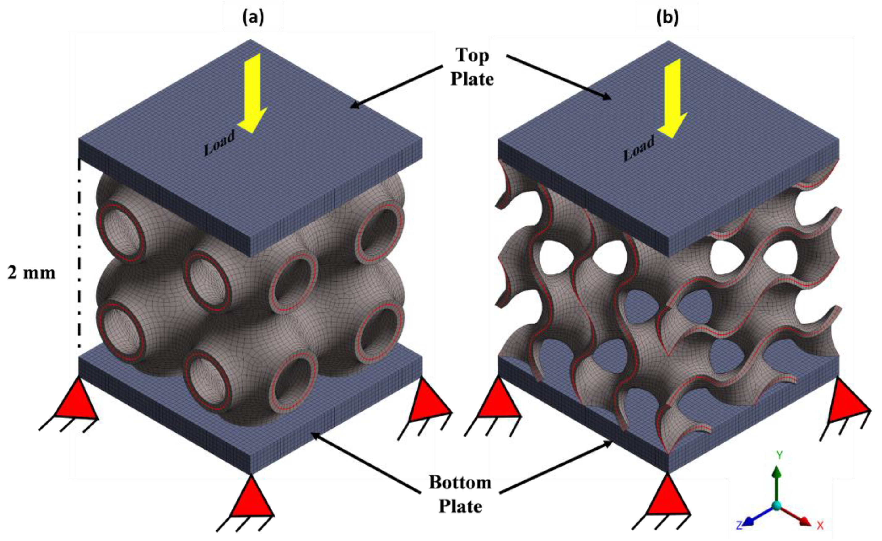
2.4. Simulation Procedure

The finite element simulation was performed on all lattices in ANSYS 2021R1 to predict the mechanical behavior. It is worth mentioning here that the lattice size used here was 2 × 2 × 2 mm3, as previous studies have suggested that the size of the lattice influences the variation of numerical outcomes. In this context, selecting a higher-order lattice size does not influence mechanical characteristics, rather it will result in a larger number of output files and a higher computational cost and memory. In lower-order lattice size, higher strains can reduce the true elastic modulus by 15% [92]. Owing to the above-mentioned issue, we selected a 2 × 2 × 2 mm3 lattice size for all the ten models in this study.
All ten scaffold models were imported into the Ansys workbench, where meshing was performed with a higher-order 3D-20-node hexahedral element (SOLID186 Element), as illustrated in Figure A1. Additionally, mesh convergence study was carried out to avoid variations in the finite element results. The mesh element size of 0.04 mm was selected for all 10 scaffold units to reduce discretization errors and maintain a balance between computational costs and outcome results. Material properties were modeled by using ANSYS material library for an elastic-plastic material model of additively manufactured Ti6Al4V with an elastic modulus of 107 GPa and Poisson’s ratio of 0.323. To capture the non-linear plastic deformation behavior, the material model contained a bilinear stress-strain diagram with isotropic hardening. The uniaxial vertical compressive load was applied to the top of the scaffold model, and the bottom was constrained, as shown in Figure A1. All ten models were compressed at a strain rate of 5%. The elastic modulus and compressive strength were evaluated by the linear region of the stress-strain diagram, and the yield strength was calculated at a 2% offset line of the linear region patterned in the x-coordinate of the stress-strain diagram.

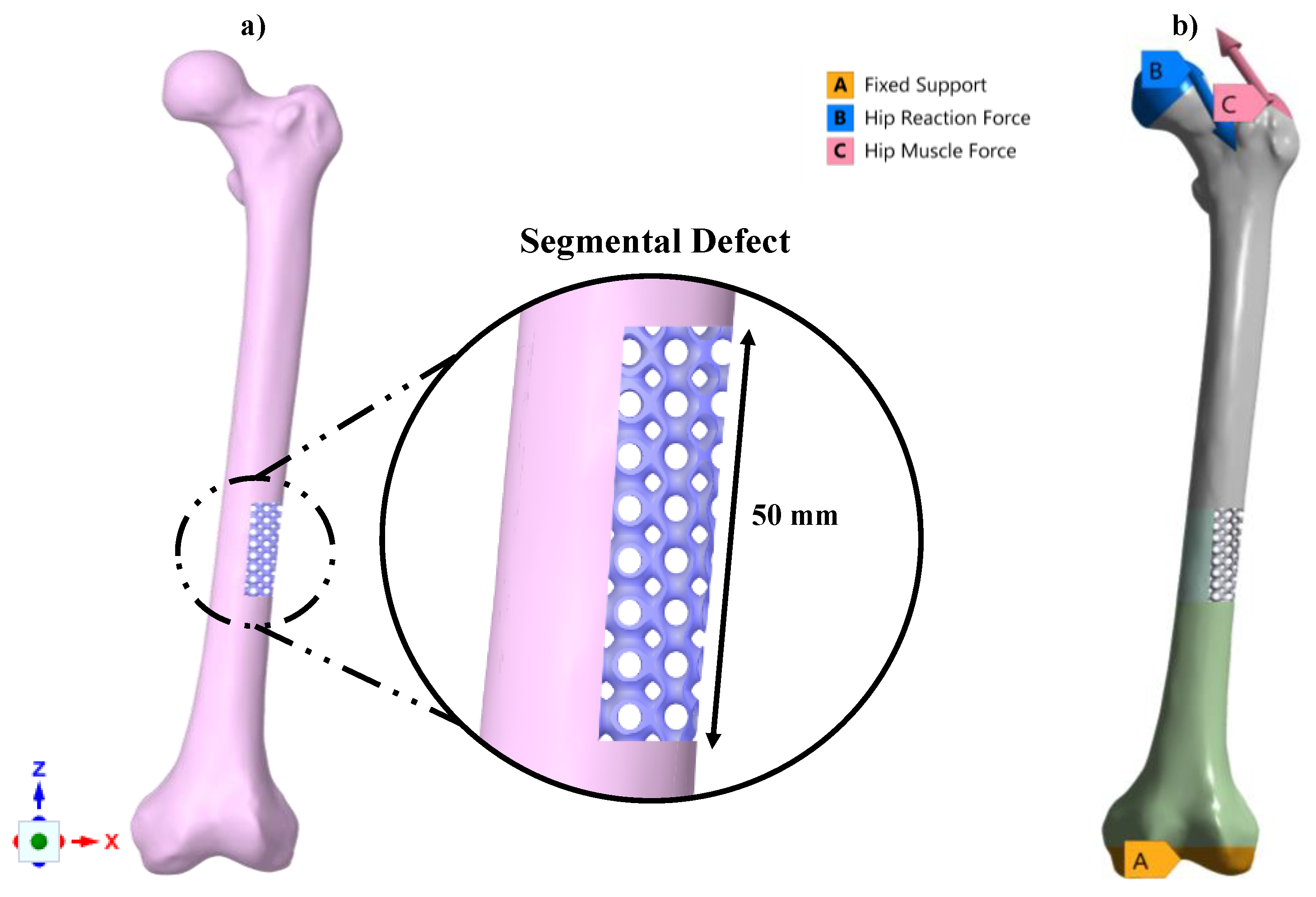
2.5. Functionality Assessment of Scaffold under Biomechanical Loading

Besides compression testing, the patient-specific scaffold was designed and placed under physiological loading conditions to assess its functionality. In addition, the purpose of the study was to demonstrate the biomechanical performance of porous implants over solid implants under physiological loading conditions.
Therefore, the constructed unit cell was used to develop patient-specific implants for critical-size femur defects of 50 mm and studied to determine their behavior in the biomechanical environment. A standard CT scan procedure was followed to obtain cross-sectional images of femur anatomical locations from the subject to generate a femur solid model, after written informed consent, followed by guidelines approved by the Ethical Committee of the Institute of Medical Sciences, Banaras Hindu University, on the use of computed tomography (CT) images. To develop a three-dimensional (3D) reconstruction of the femur bone, Materialise MIMICS 18.0 (Materialise, Leuven, Belgium) software was utilized. A semi-automatic algorithm, known as region-grow, was applied with a Hounsfield threshold range of 230 to 1883 HU, that adequately captured the cortical and cancellous range to extract the bony part of the femur. Figure A2 (left) depicts cross-sectional views of the femur in various orientations, whereas Figure A2 (right) depicts the 3D model. The model was exported in STL format to the FreeCAD software package and a similar procedure discussed in Section 2.2 was employed to convert femur STL to Solid Initial Graphics Exchange Specification (IGES) format.
In the next step, the solid femur was imported to the SpaceClaim workspace (2021 R1, SpaceClaim Corp., Concord, MA, USA) and a section cut on the femur bone was performed to surgically create the segmental bone defect. However, it should be highlighted that the segments representing critical defects were chosen at random and did not reflect a real-world problem against which the implant attempts to intervene in clinical practice.
The unit cell recruited for this study was P with 80% porosity and was scaled from 1 × 1 × 1 mm3 to 6.28 × 6.28 × 6.28 mm3 on the same porosity of 80% to reduce significant computational cost (both time and memory), irrespective of utilizing the studied unit cell of 1 × 1 × 1 under compressive loading conditions. The scaffold unit was created by linear patterning of the unit cell in x, y, and z global coordinates, and was kept larger than the created femur defect. The anatomically matched porous scaffold was constructed using the Boolean intersection [74,75,76,77] of the defected bone with the patterned large scaffold unit, as shown in Figure 4a.
The assembled model was imported into ANSYS for mechanical analysis. The femur geometry meshed with higher-order 3D, 10 node tetrahedral elements (SOLID 187) with an edge length of 2 mm to adequately discretize the strut cross-sections, whereas the scaffold unit was meshed with a tiny edge length of 0.3 mm. Table A1 shows the number of nodes and elements for each component of the model.
The material properties of the femur, which were linear orthotropic and assigned uniformly to the femur bone, were adopted from [93] and summarized in Table A2. The material model for the scaffold was the same Ti6Al4V alloy that was assigned during the evaluation of the mechanical properties of lattices on compressive loading.
Additionally, to identify the difference in stress transfer between porous and solid scaffolds to the surrounding bone, the porous scaffold was replaced with an anatomically comparable solid scaffold and examined under the same physiological loading conditions.
Finally, the model was subjected to loading and boundary conditions for a single leg stance case adopted from the literature [94], for which the distal section of the femur was fixed, and hip reaction forces and muscle forces were applied to the model via a selection of the surface of the femur on the locations, as shown in Figure 4b, and values were tabulated in Table A3. A bonded contact was used to avoid sliding between the femur bone scaffold interfaces.

3. Results and Discussion

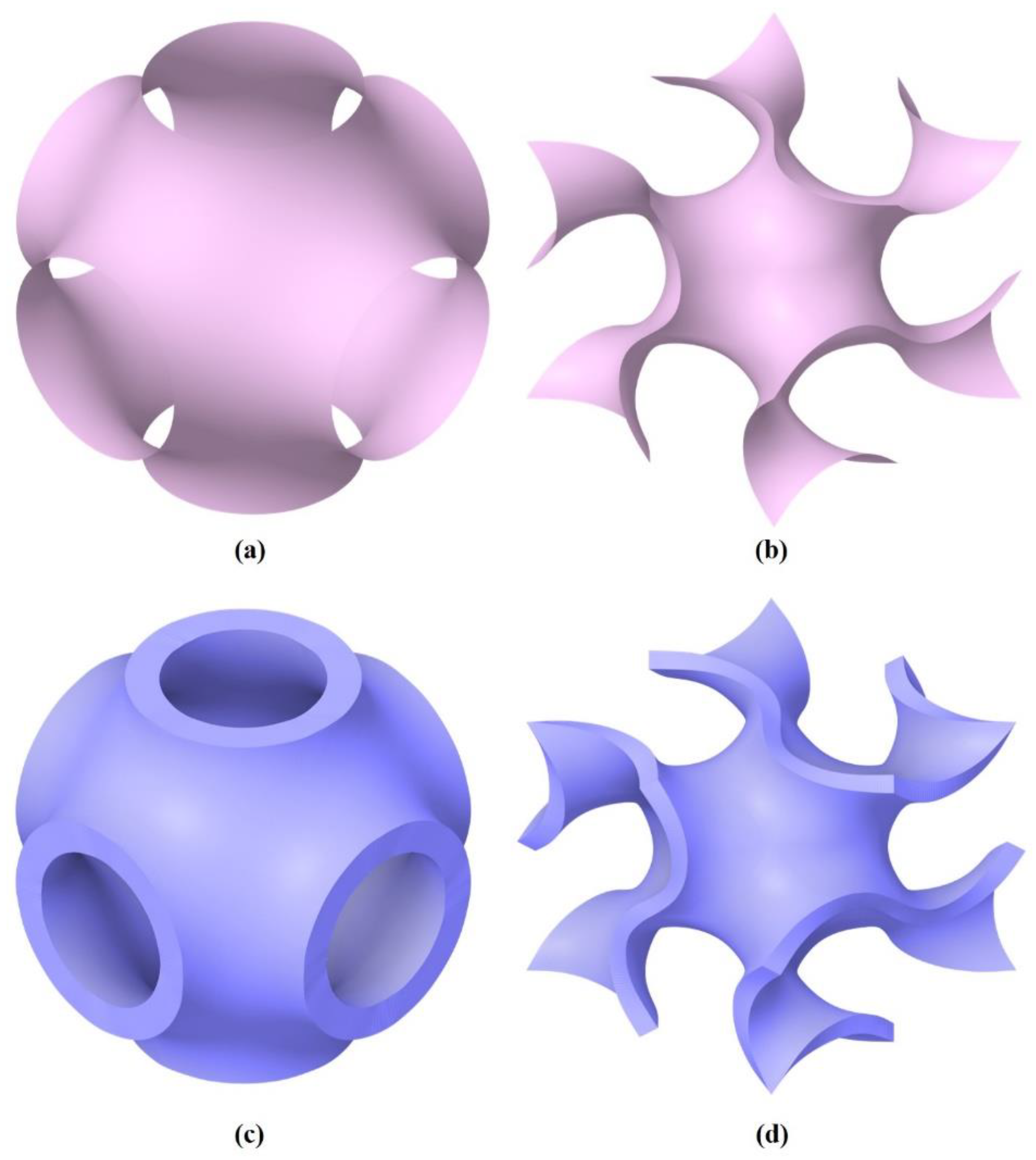
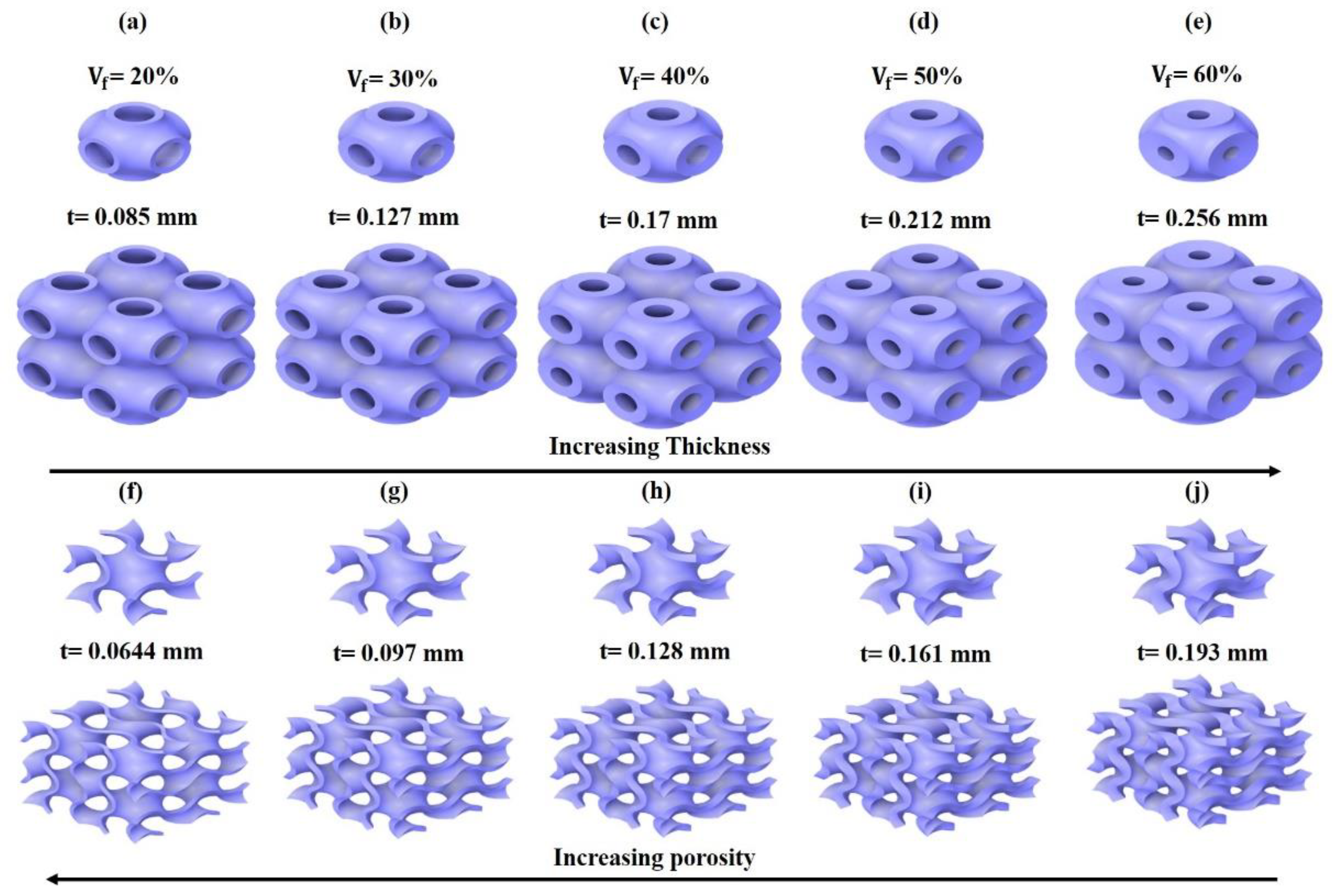
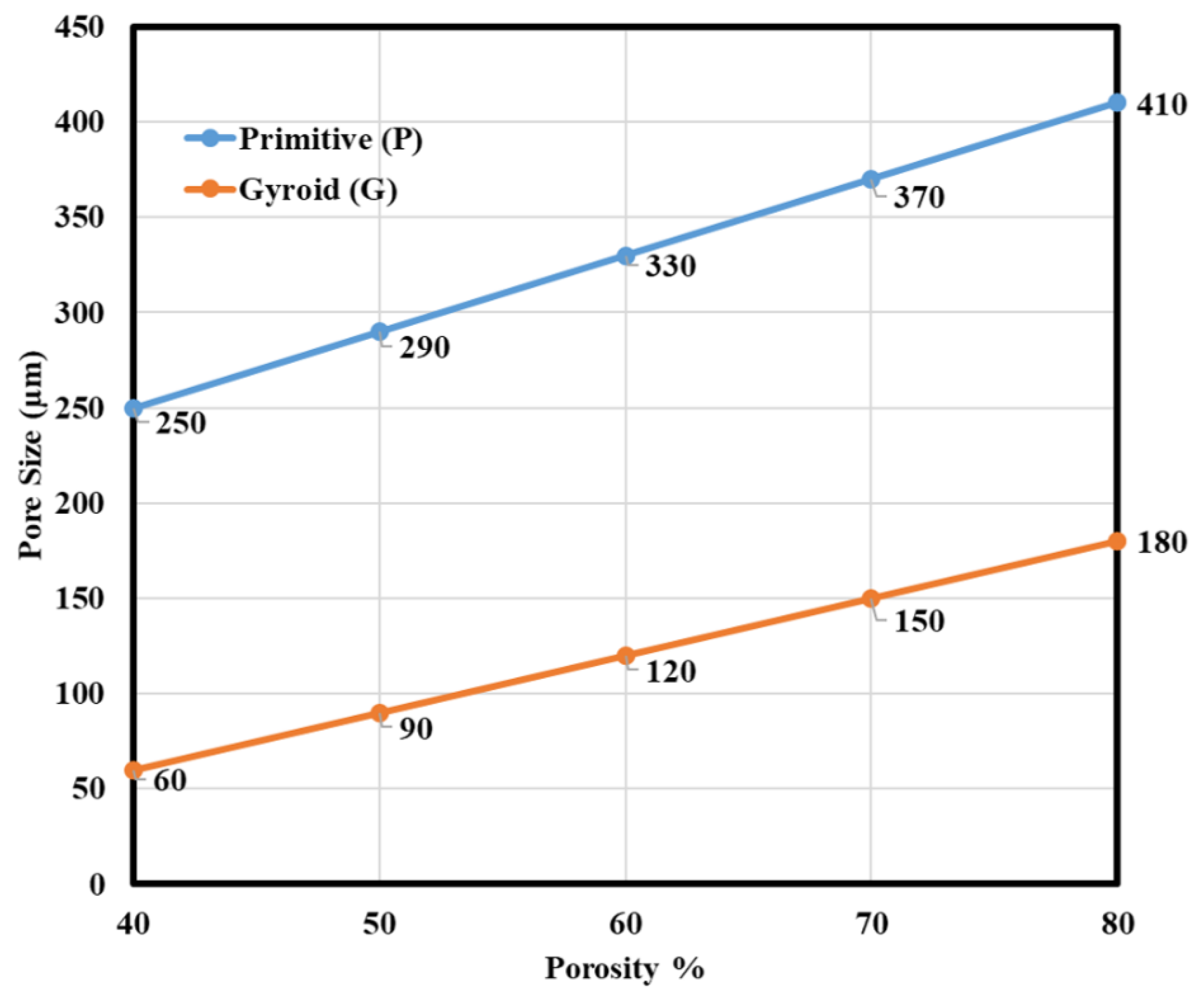
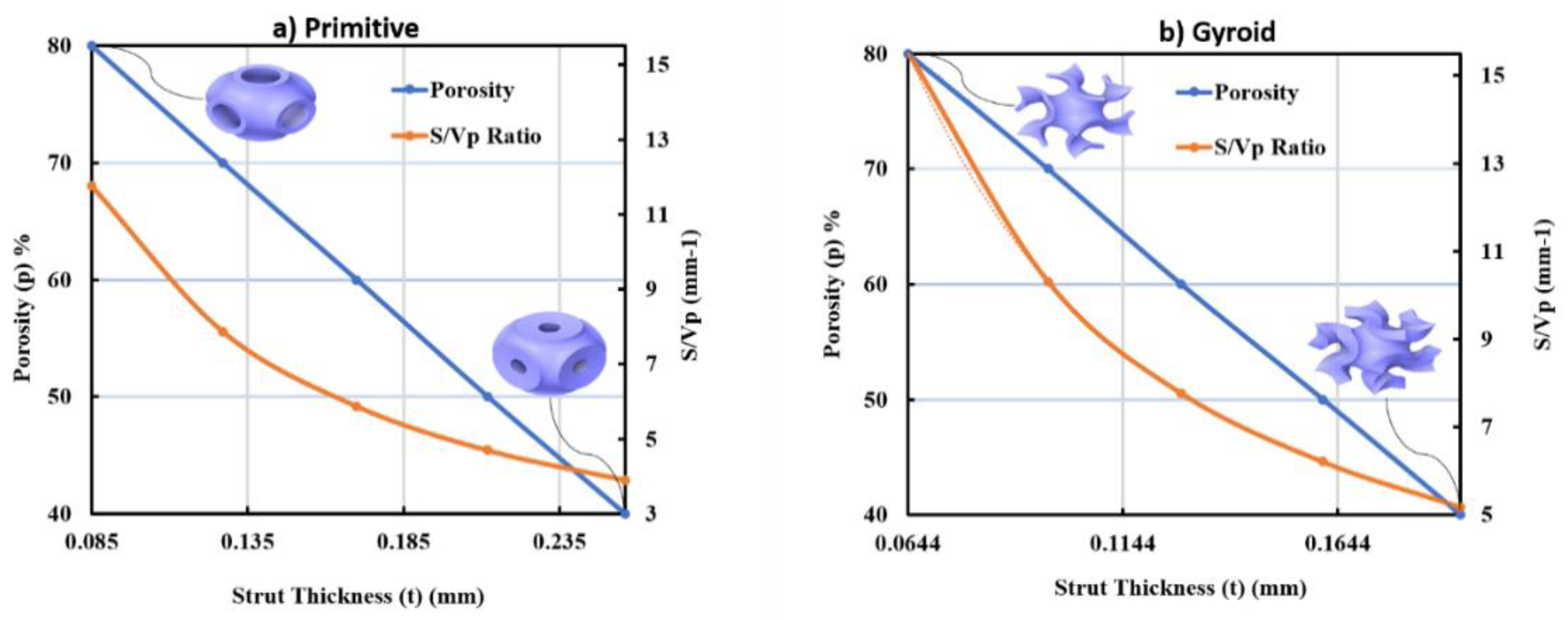
3.1. Morphological Results Obtained from the Developed TPMS Cells

A variation in pore size and strut thickness was achieved by simultaneously controlling the level set constant (c) of Equations (5) and (6) to achieve varying porosities of unit cells. Due to the periodic nature of TPMS in all directions, the pore sizes were the same for both P and G unit cells. Figure 5 compares the key morphological parameters between P and G structures in porosity and pore sizes. It was observed from the results that the pore size of P unit cells was higher in comparison to G for all the porosity levels. For the increase in the porosity level there was a linear increase in pore sizes for both P and G unit cells. Open systems having pore sizes above 100 µm were found suitable for cell integration as well as vessel regeneration [95,96]. From Figure 5, P unit cells with porosities ranging from 40% to 80% were confirmed to have pore sizes larger than 100 µm, while G unit cells, which possessed only the unit cell having porosities in the range 60% to 80%, showed pore size greater than 100 µm.
Surface area to volume ratio (S/VP) is an important parameter when designing a scaffold with porous unit cells. Previous research on these geometrical aspects claimed that a larger surface area improves cell adhesion and bone ingrowth, as well as promotes cell proliferation metrics [97]. The volume and surface of each unit cell were calculated by CAD measuring features. The surface area increased with the increase of porosity and, contrarily, it decreased as the thickness of cells increased and vice versa. Figure 6a,b are the graphs for strut thickness (t) versus scaffold porosity and surface to volume ratio (S/VP) for P and G structures. Based on the data obtained from the measurement of geometrical parameters, a relationship was developed using a polynomial fit ( R 2 = 1 ) between the thickness parameter (t), scaffold porosity (p), and S/VP ratio. Established Equations (9)–(16) are listed below.
  • For the P unit cell:
U = 10409 t 4     8747 . 8 t 3 + 2853 . 2 t 2     450 . 32 t + 34 . 256
p = 27 . 637 t 2     243 . 6 t + 100 . 51
t = 2 × 10 6 p 2     0 . 0045 p + 0 . 4335
t = 0 . 0001 ( U ) 4     0 . 0043 ( U ) 3 + 0 . 0544 ( U ) 2     0 . 324 ( U ) + 0 . 92
  • For the G unit cell:
U = 30234 t 4     20734 t 3 + 5510 . 9 t 2     705 . 08 t + 43 . 097
p = 81173 t 4 + 42299 t 3     7876 t 2 + 304 . 38 t + 83 . 161
t = 5   ×   10 8 p 3 + 1   ×   10 5 p 2     0 . 0038 p + 0 . 3331
t = 2   ×   10 5 ( U ) 4     0 . 0008   ( U ) 3 + 0 . 0151   ( U ) 2     0 . 1375   ( U ) + 0 . 5989
where (U) represents the surface area to volume ratio (S/VP), (p) is the corresponding unit cell porosity, and (t) is the strut thickness of the corresponding unit cell.
These equations can be used directly to parametrize both P- and G-based unit cells and can be directly modeled and manufactured for specific needs. From Figure 6a,b, it is evident that a high surface area to volume ratio maximized the structural porosity, thereby increasing the permeability and decreasing the elastic modulus and strength. A parametric relationship could also be obtained between p, S/VP, and the elastic modulus of these structures. These correlations may be beneficial for the characterization, as well as the manufacture, of optimized implants in osseous reconstruction to improve bone ingrowth, cell adhesion, and promote osseointegration.

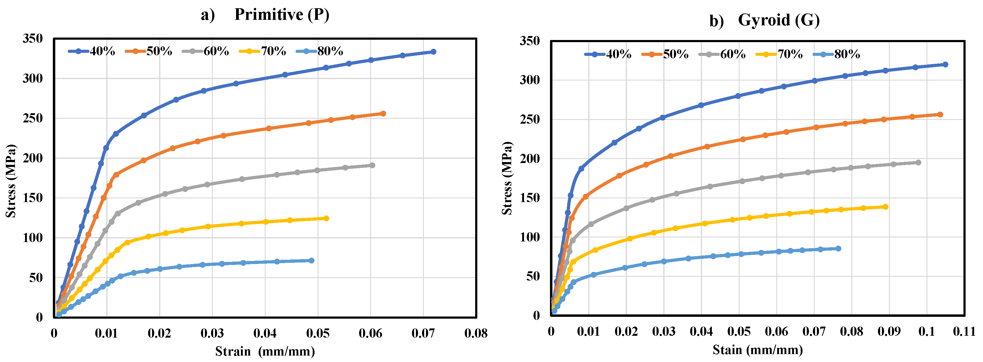
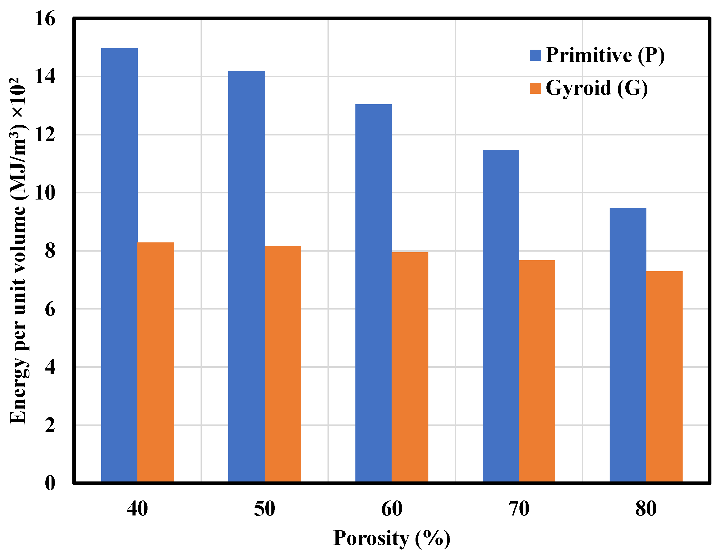
3.2. Mechanical Properties of the P and G TPMS Lattice

Mechanical properties of developed P and G lattices were characterized by numerical finite element analysis with varying porosities by the method mentioned in Section 2.4. Figure 7a,b depict a typical stress-strain curve of P and G lattice structures with porosities ranging from 40% to 80%.
Observing the stress-strain plot of P and G on similar porosities revealed a slightly distinct behavior. The G exhibited a typical brittle behavior as plastic deformation occurred at small strains, whereas the P exhibited a typical ductile behavior as plastic deformation began at a slightly higher strain.

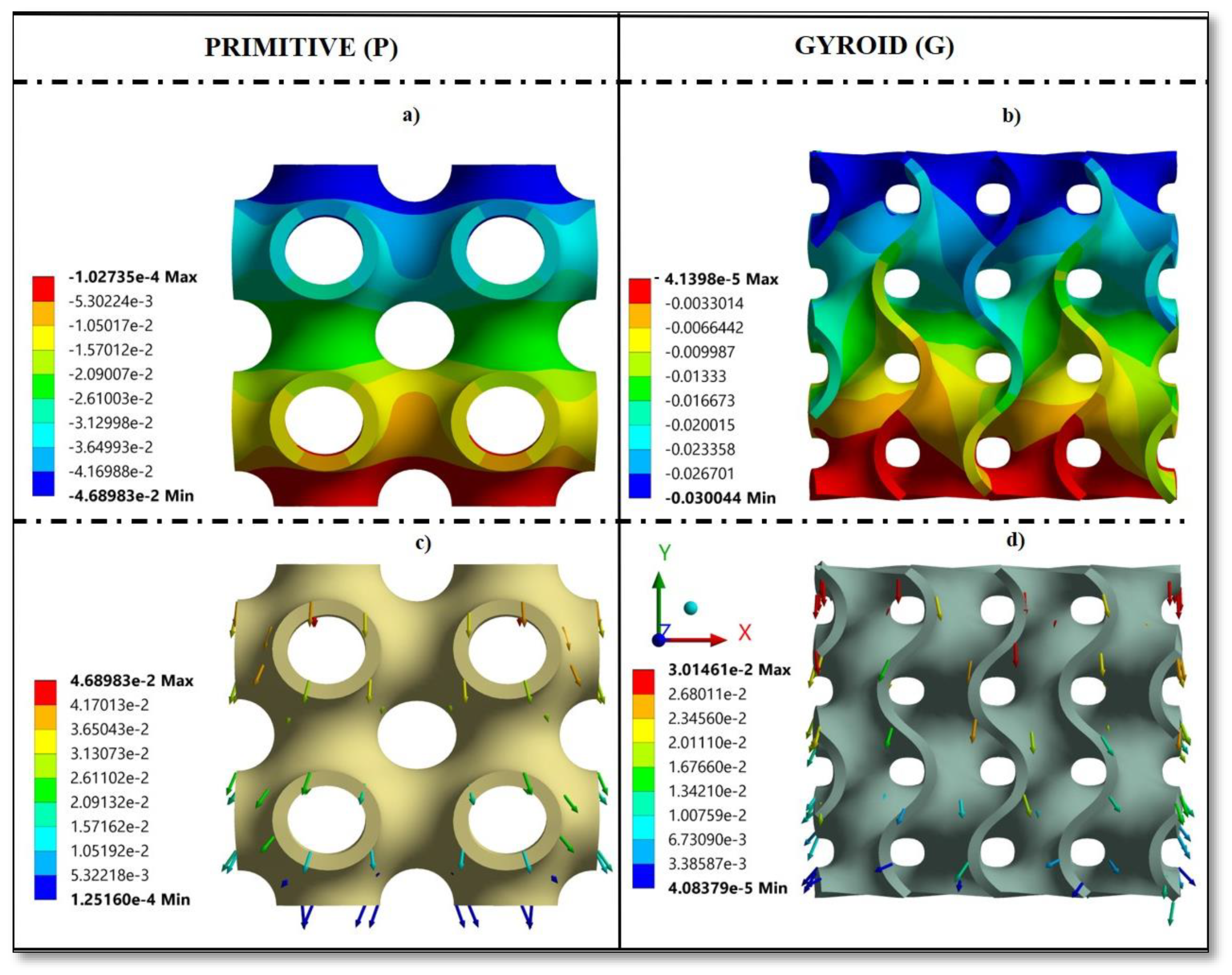
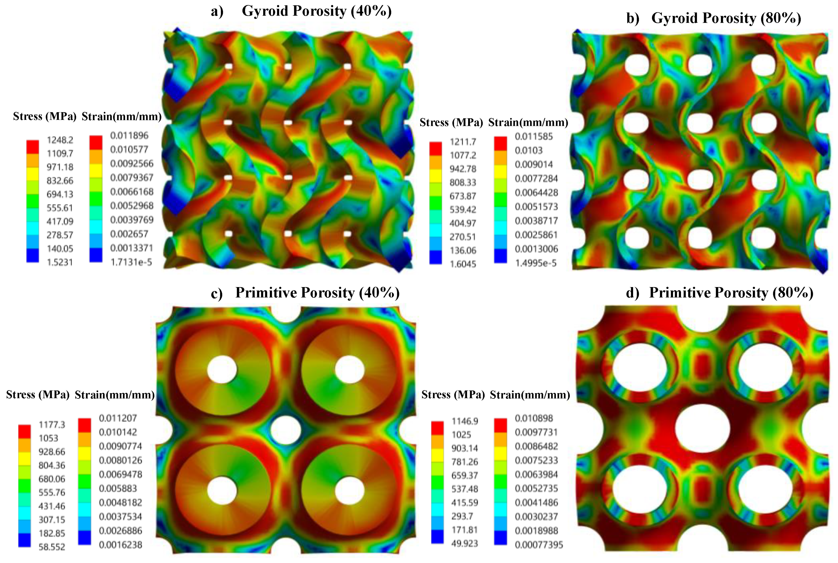
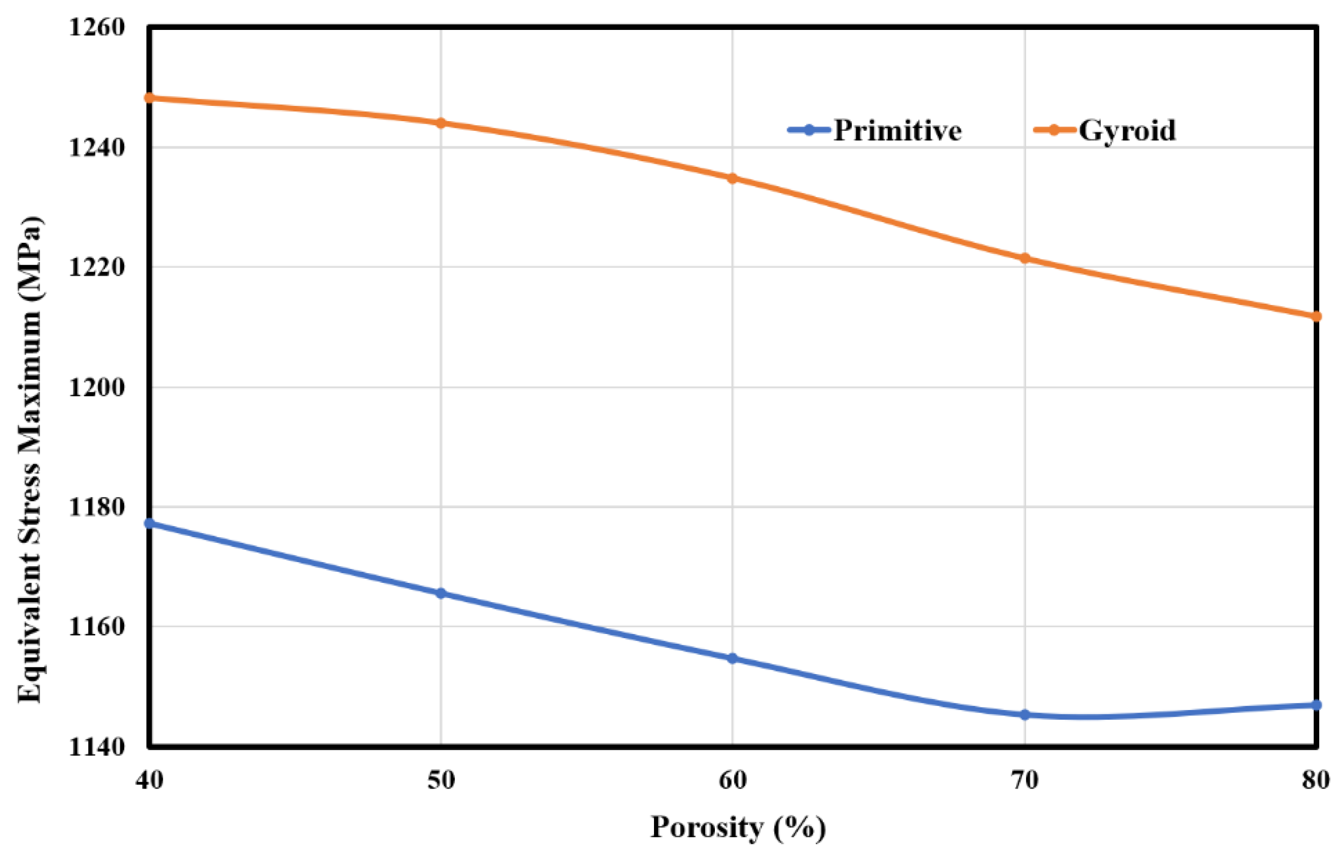
3.3. Stress and Strain Pattern

The stress and strain patterns for P and G are shown in Figure 8. Contour plots are only presented for 40% and 80% porosity for both P and G. From Figure 8, it can be observed that the distribution pattern of stress and strain on the structure was exactly similar for particular porosities of each structure. From Figure 8a,b, it can be noticed that the stresses and strains were lowest at the open edges of the struts (two struts at the left and right in Figure 8a,b), which implies that there was no force transmission at these locations. This suggests that while designing the scaffolds based on G lattice structures, these struts must be avoided. Additionally, these struts would only contribute to scaffolds with sharp edges and corners which could compromise critical safety features [98].
Also, from Figure 8a,b, it can be noticed that there were less stress and strain concentrations at the edges as compared to the neck regions that connect each unit cell. The higher stress and strain at the neck region signified that upon loading, the deformations would first occur at these sites.
To investigate the stress level for varying porosities, an equivalent Von Mises stress maximum was plotted against the porosity level for both P and G and is demonstrated in Figure 9. The overall stress for each porosity level was always lower in P when compared to G. Figure 9 clearly shows that there was a gradual decrease in stress when porosity was increased. There was an obvious pattern of a gradual decrease in stiffness, which can be seen in Table 1. G lattice at 40% porosity exhibited the highest stress of 1248.2 MPa, whereas it was lowest at 80% porosity of 1211.7 MPa. The P lattice had a comparatively lower range of maximum stress in comparison to the G lattice, among which P, with 40% porosity, exhibited the highest stress of 1177.3 MPa, whereas 70% porosity had the lowest value of 1145.3 MPa.
Figure A3 illustrates the directional deformation and total deformation vector of P and G lattice structures with similar porosity of 80% on the compressive strain of 0.04. P exhibited higher deformation in comparison to the G lattice structure, as shown in Figure A3a,b. Observing the directional deformation of P, Figure A3a illustrates that high concentrations at the bottom region were normal to the loading direction and Figure A3c shows that total deformation vector directions on four pores, excluding the central pore, were aligned towards the loading direction and exhibited P’s stretching dominant behavior. Observing the directional deformation of G, amongst the central struts (three continuous struts in the core region) and the lateral struts in Figure A3b, the central struts had higher strain concentrations and were aligned in a parallel loading direction. Also, the total deformation vectors from Figure A3d show that the strut deformation vectors were slightly diverted from the vertical direction, indicating bending dominant behavior.
Table 1 summarizes the effective Young’s modulus and compressive yield strength of the P and G lattice structures on porosities ranging from 40% to 80%. Young’s modulus and strength decreased with increase in porosity of the lattice structures. The effective modulus for a P lattice with 80% porosity was 4.21 GPa, which was approximately 80% lower than that of the P lattice with a porosity of 40%. The compressive yield strength for a P lattice with 80% porosity was 56 MPa, which was approximately 76% lower than that of the G lattice having a porosity of 40%. Similar trends were observed in the G lattice: effective Young’s modulus for 40% porosity was 29.63 GPa and for 80% porosity was 7.16 GPa, which confirmed a decrease of approximately 75%. Also, compressive yield strength had a reduction ratio of approximately 74%, from 40% to 80%. However, this behavior was expected, due to the variation in measured Vp. Comparing the effective Young’s modulus between P and G lattice structures among all the porosity levels, P always showed a decreasing trend. It is noteworthy that compressive yield strength showed an increasing trend in G as compared to P in all porosities.
Besides implants used for the treatment of bone defects, it is important to have mechanical characteristics of implants comparable to the natural bone to minimize bone resorption, which leads to the stress shielding phenomena [99]. Also, the compressive property of bone is an essential mechanical characteristic that varies from one anatomical site to another and also has a substantial age dependency. As a result of this study, accounting for the reduced modulus (effective elastic modulus) and compressive yield strength would be a possible option for designing a scaffold that resembles the property of bone at anatomical sites where the scaffold would be placed.
The energy absorption property of porous scaffolds is an important performance index, as they can transmit energy, which aids in propagating stress over the porous scaffold and may act as an impact resistance for bones [100]. The energy absorption capacity of both P and G was determined by Equation (17) with varying porosities, and is demonstrated in Figure A4. The specific energy absorbed (SEA) by the lattice structure was defined as the energy absorbed per structural weight under compression. It was obvious from Figure A4, that stretching dominant structures (P Lattice) had a higher potential for energy absorption than the bending dominant (G Lattice) structures. Therefore, P structures had much higher SEA than G lattice structures as they could bear more compressive strains in actual practice. On the contrary, considering specific energies of both P and G, the value ranged between 7.2 and 14.9 MJ/m3, which is considerably higher compared to the other porous structures [101]. However, energy absorption application requires energy absorbed per unit volume and the corresponding maximum stress of the structure. More specifically, when considering porous structures, they should absorb most of the energy on the maximum permitted stress [102].
SEA = Energy   absorbed   by   the   scaffold Structural   weight   of   the   scaffold

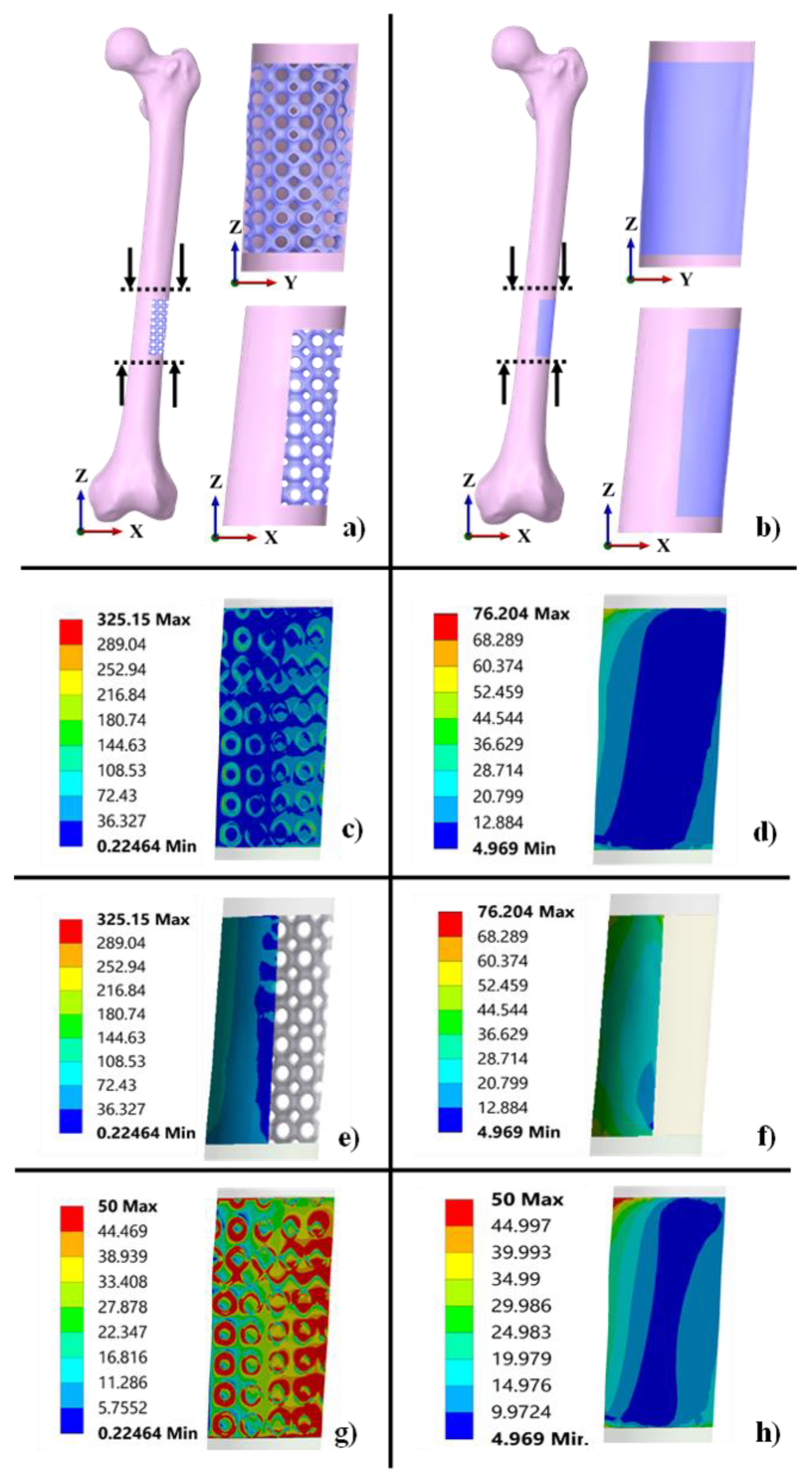
3.4. Functionality Assessment of Scaffold under Biomechanical Loading

The 3D models of P-based scaffold and solid scaffold mimicking the treatment of critical size bone defects were developed from the method mentioned in Section 2.5. The models were analyzed under physiological loading conditions. Equivalent Von mises stress patterns are shown in Figure 10c–f. From Figure 10c–e it can be observed that the stress transmission through the bone was 325 MPa when using a porous scaffold. Whereas from Figure 10d–f, it can be observed that stress transmission was reduced to 76.204 MPa i.e., a net reduction of approx. 76%, which implied that there was a notable modulus mismatch between the surrounding bone and the solid scaffold. However, using a porous scaffold gives a prominent modulus match between surrounding bone and porous scaffold which leads to more transfer of stresses on the surrounding bone. As a result, when comparing the stress transfer characteristics of porous and solid scaffolds, it is observed that using porous scaffolds provides a promising mechanical stimulus to the bone. The implant interface induces bone tissue regeneration and also subsequent increase in interface strength which promotes restrictions to stress shielding following bone resorption and implant loosening. Furthermore, to demonstrate the stress concentration on the bone which leads to the stress shielding phenomenon, we adjusted the upper value to 50 MPa of stress on both the models, as shown in Figure 10g,h. From the results obtained, as shown in Figure 10h, stress concentration was observed in the top left area (red-colored region) which signified that the stress shielding effect was very high when using a solid scaffold. On the contrary, from Figure 10g, it could be observed that when a porous scaffold was used, stress concentration was not at particular locations, instead it was equally distributed to the area of bone and scaffold interface. However, due to manufacturing errors that substantially cause a reduction in mechanical properties, the FEA of scaffolds approximates the mechanical properties of additively produced scaffolds. According to previous studies, surface roughness can cause a 66 percent increase in finite element analysis findings [103]. As a result, it is always essential to obtain the relation between constructed scaffold parameters and overall mechanical properties for each scaffold, as well as additive manufacturing features, for the purpose of confirmed validation and referencing for scaffold functionality, especially in patient-specific scenarios.

4. Conclusions

The structural design and analysis of the TPMS-based porous scaffold is an important factor for determining the pre-clinical performance of the implant to treat segmental bone defects. The morphological properties (pore shape and size, strut thickness, and porosity) of porous scaffolds are the basic controlling parameters that greatly influence their overall performance. However, an optimum balance between the structural-mechanical properties to obtain complex porous structures and their integrity at specific locations is challenging.
In contribution to this, the present study proposed the development of 3D porous scaffolds of P and G TPMS structures with porosities ranging from 40% to 80%. An efficient approach for converting STL models into solid models (in STEP or IGES format) was proposed to reduce the redundancy of STL models used in the FEA process. Morphological analysis was performed to evaluate the mechanical behavior. The results revealed the correlation of porosity with pore size and strut thickness and developed a relationship in which any level of porous structures can be conveniently modeled on the following strut thickness. TPMS-based P and G porous structures modeled by Ti6Al4V material exhibited low effective modulus, coordinating with Young’s modulus range of human cortical and cancellous bone. The results revealed that P demonstrated superior properties, in terms of compressive strength and SEA characteristics, and G demonstrated superior properties, in terms of effective elastic modulus, and, therefore, both could be used for patient-specific scaffolds, depending on the parameters favorable for the anatomical locations of bone.
In comparison to the solid scaffolds, the porous P-based TPMS structures effectively reduced the stress shielding phenomenon which suggests that TPMS-based porous structures have the potential to reduce the stiffness mismatch between the bone-implant interface. A further extensive study will illustrate the full potential of the suggested TPMS-based (P and G) scaffolds on the grounds of experimental investigation to study the strength and failure mechanisms at various modes of loading, computational and experimental investigations for permeability analysis, and clinical validation for assessing real scenarios of biocompatibility and tissue responses.

Author Contributions

Conceptualization, N.K.S., S.K.R. and R.V.; methodology, R.V. and J.K.; validation, N.K.S., K.K.S. and S.K.R.; formal analysis, R.V. and J.K.; investigation, N.K.S. and R.V.; writing—original draft preparation, N.K.S. and J.K.; writing—review and editing, N.K.S. and J.X.; project administration, N.K.S. and J.X.; funding acquisition, K.K.S. All authors have read and agreed to the published version of the manuscript.

Funding

This research received no external funding.

Institutional Review Board Statement

The study was conducted in accordance with the Declaration of Helsinki, and approved by the Ethics Committee of Institute of Medical Sciences, Banaras Hindu University (IMS BHU) (No. Dean/2015-16/EC/1680; 19 March 2016).

Informed Consent Statement

Stated clearly in Section 2.5.

Data Availability Statement

Not applicable.

Acknowledgments

The authors would like to acknowledge the Department of Radio diagnosis Imaging, Institute of Medical Sciences, Banaras Hindu University, Varanasi, India for providing patient data.

Conflicts of Interest

The authors declare no conflict of interest.

Appendix A

Figure A1. Representative boundary condition and hexahedral meshing (a) P, 80% Porosity (b) G, 80% Porosity.
Coatings 12 00839 g0a1
Figure A2. (Left): The cross−sectional images of the femur in axial, coronal, and sagittal views show the threshold of the bony area. (Right): Generated 3D solid model of femur used in the study.
Coatings 12 00839 g0a2
Table A1. Number of elements and nodes generated in each component of the model for finite element analysis.
ComponentElement SizeTotal No. of ElementsTotal No. of Nodes
Femur without scaffold2 mm1,074,8301,612,424
P Scaffold0.3 mm662,6581,164,054
Solid Scaffold2 mm275214,790
Table A2. Adopted orthotropic material properties for finite element femur construct.
PropertyValue
Density1.8 × 10−6 kg·mm−3
Engineering Constants
E111.5 GPa
E211.5 GPa
E317.0 GPa
G123.6 GPa
G133.28 GPa
G233.28 GPa
ν120.58
ν130.31
ν230.31
ν210.58
ν310.46
ν320.46
Table A3. Applied Loads on the model.
LocationDirectional Coordinates
XYZ
Hip Reaction Force (N)1492−915−2925
Hip Muscle Force (N)−13428322055
Figure A3. State of deformation along Y-axis (a,b), and total deformation vector display (c,d), of lattice structures at 80% porosity.
Coatings 12 00839 g0a3
Figure A4. Summary of SEA results for P and G lattice structures based on different porosities ranging from 40% to 80%.
Coatings 12 00839 g0a4

References

  1. Reichert, J.C.; Saifzadeh, S.; Wullschleger, M.E.; Epari, D.R.; Schütz, M.A.; Duda, G.N.; Schell, H.; Van, G.M.; Redl, H.; Hutmacher, D.W. The challenge of establishing preclinical models for segmental bone defect research. Biomaterials 2009, 30, 2149–2163. [Google Scholar] [CrossRef] [PubMed] [Green Version]
  2. Dekker, T.J.; Steele, J.R.; Federer, A.E.; Hamid, K.S.; Adams, S.B., Jr. Use of patient-specific 3D-printed titanium implants for complex foot and ankle limb salvage, deformity correction, and arthrodesis procedures. Foot Ankle Int. 2018, 39, 916–921. [Google Scholar] [CrossRef] [PubMed]
  3. Wong, K.C.; Kumta, S.M.; Geel, N.V.; Demol, J. One-step reconstruction with a 3D-printed, biomechanically evaluated custom implant after complex pelvic tumor resection. Comput. Aided Surg. 2015, 20, 14–23. [Google Scholar] [CrossRef] [PubMed]
  4. Wong, K.C.; Kumta, S.M. Joint-preserving tumor resection and reconstruction using image-guided computer navigation. Clin. Orthop. Relat. Res. 2013, 471, 762–773. [Google Scholar] [CrossRef] [Green Version]
  5. Zekry, K.M.; Yamamoto, N.; Hayashi, K.; Takeuchi, A.; Alkhooly, A.Z.; Abd-Elfattah, A.S.; Elsaid, A.N.; Ahmed, A.R.; Tsuchiya, H. Reconstruction of intercalary bone defect after resection of malignant bone tumor. J. Orthop. Surg. Res. 2019, 27, 1–9. [Google Scholar] [CrossRef] [Green Version]
  6. Kumta, S.M.; Leung, P.C.; Yip, K.; Hung, L.K.; Panozzo, A.; Kew, J. Vascularized Bone Grafts in the Treatment of Juxta-Articular Giant-Cell Tumors of the Bone. J. Reconstr. Microsurg. 1998, 14, 185–190. [Google Scholar] [CrossRef]
  7. Kumta, S.M.; Leung, P.C.; Griffith, J.F.; Roebuck, D.J.; Chow, L.T.; Li, C.K. A technique for enhancing union of allograft to host bone. J. Bone Jt. Surg. Br. Vol. 1998, 80, 994–998. [Google Scholar] [CrossRef]
  8. Mauffrey, C.; Barlow, B.T.; Smith, W. Management of segmental bone defects. J. Am. Acad. Orthop. Surg. 2015, 23, 143–153. [Google Scholar] [CrossRef]
  9. Mavrogenis, A.F.; Sakellariou, V.I.; Tsibidakis, H.; Papagelopoulos, P.J. Adamantinoma of the tibia treated with a new intramedullary diaphyseal segmental defect implant. J. Int. Med. Res. 2009, 37, 1238–1245. [Google Scholar] [CrossRef]
  10. Healey, J.H.; Morris, C.D.; Athanasian, E.A.; Boland, P.J. Compress® knee arthroplasty has 80% 10-year survivorship and novel forms of bone failure. Clin. Orthop. Relat. Res. 2013, 471, 774–783. [Google Scholar] [CrossRef] [Green Version]
  11. Ruggieri, P.; Mavrogenis, A.F.; Bianchi, G.; Sakellariou, V.I.; Mercuri, M.; Papagelopoulos, P.J. Outcome of the intramedullary diaphyseal segmental defect fixation system for bone tumors. Journal of Surgical Oncology. J. Surg. Oncol. 2011, 104, 83–90. [Google Scholar] [CrossRef] [PubMed]
  12. Hanna, S.A.; Sewell, M.D.; Aston, W.J.; Pollock, R.C.; Skinner, J.A.; Cannon, S.R.; Briggs, T.W. Femoral diaphyseal endoprosthetic reconstruction after segmental resection of primary bone tumours. J. Bone Jt. Surg. Br. Vol. 2010, 92, 867–874. [Google Scholar] [CrossRef] [PubMed] [Green Version]
  13. Qin, Z.; Jung, G.S.; Kang, M.J.; Buehler, M.J. The mechanics and design of a lightweight three-dimensional graphene assembly. Sci. Adv. 2017, 3, 1–8. [Google Scholar] [CrossRef] [Green Version]
  14. Matassi, F.; Botti, A.; Sirleo, L.; Carulli, C.; Innocenti, M. Porous metal for orthopedics implants. Clin. Cases Miner. Bone Metab. 2013, 10, 111–115. [Google Scholar] [CrossRef] [PubMed]
  15. Dabrowski, B.; Swieszkowski, W.; Godlinski, D.; Kurzydlowski, K.J. Highly porous titanium scaffolds for orthopaedic applications. J. Biomed. Mater. Res. Part B Appl. Biomater. 2010, 95, 53–61. [Google Scholar] [CrossRef] [PubMed]
  16. Pałka, K.; Pokrowiecki, R. Porous titanium implants: A review. Adv. Eng. Mater. 2018, 20, 1700648. [Google Scholar] [CrossRef]
  17. Rati, V.; Singh, N.; Rai, S.; Kumta, S. Triply periodic minimal surface-based porous scaffold design and analysis subjected to hard tissue reconstruction. In Advances in Computational Methods in Manufacturing; Narayanan, R.G., Joshi, S.N., Dixit, U.S., Eds.; Springer: Singapore, 2019; pp. 955–966. [Google Scholar] [CrossRef]
  18. Al-Ketan, O.; Abu Al-Rub, R.K. Multifunctional mechanical metamaterials based on triply periodic minimal surface lattices. Adv. Eng. Mater. 2019, 21, 1900524. [Google Scholar] [CrossRef]
  19. Afshar, M.; Anaraki, A.P.; Montazerian, H.; Kadkhodapour, J. Additive manufacturing and mechanical characterization of graded porosity scaffolds designed based on triply periodic minimal surface architectures. J. Mech. Behav. Biomed. Mater. 2016, 62, 481–494. [Google Scholar] [CrossRef]
  20. Yánez, A.; Cuadrado, A.; Martel, O.; Afonso, H.; Monopoli, D. Gyroid porous titanium structures: A versatile solution to be used as scaffolds in bone defect reconstruction. Mater. Des. 2018, 140, 21–29. [Google Scholar] [CrossRef]
  21. Yoo, D.J. Recent trends and challenges in computer-aided design of additive manufacturing-based biomimetic scaffolds and bioartificial organs. Int. J. Precis. Eng. Manuf. 2014, 15, 2205–2217. [Google Scholar] [CrossRef]
  22. Abueidda, D.W.; Elhebeary, M.; Shiang, C.S.; Pang, S.; Al-Rub, R.K.; Jasiuk, I.M. Mechanical properties of 3D printed polymeric Gyroid cellular structures: Experimental and finite element study. Mater. Des. 2019, 165, 107597. [Google Scholar] [CrossRef]
  23. Herrera, A.; Yánez, A.; Martel, O.; Afonso, H.; Monopoli, D. Computational study and experimental validation of porous structures fabricated by electron beam melting: A challenge to avoid stress shielding. Mater. Sci. Eng. C 2014, 45, 89–93. [Google Scholar] [CrossRef] [PubMed]
  24. Wieding, J.; Wolf, A.; Bader, R. Numerical optimization of open-porous bone scaffold structures to match the elastic properties of human cortical bone. J. Mech. Behav. Biomed. Mater. 2014, 37, 56–68. [Google Scholar] [CrossRef] [PubMed]
  25. Maskery, I.; Sturm, L.; Aremu, A.O.; Panesar, A.; Williams, C.B.; Tuck, C.J.; Wildman, R.D.; Ashcroft, I.A.; Hague, R.J. Insights into the mechanical properties of several triply periodic minimal surface lattice structures made by polymer additive manufacturing. Polymer 2018, 152, 62–71. [Google Scholar] [CrossRef]
  26. Karageorgiou, V.; Kaplan, D. Porosity of 3D biomaterial scaffolds and osteogenesis. Biomaterials 2005, 26, 5474–5491. [Google Scholar] [CrossRef]
  27. An, Y.H.; Draughn, R.A. Mechanical Testing of Bone and the Bone-Implant Interface, 1st ed.; CRC Press: Boca Raton, FL, USA, 1999. [Google Scholar]
  28. Kapat, K.; Srivas, P.K.; Rameshbabu, A.P.; Maity, P.P.; Jana, S.; Dutta, J.; Majumdar, P.; Chakrabarti, D.; Dhara, S. Influence of porosity and pore-size distribution in Ti6Al4 V foam on physicomechanical properties, osteogenesis, and quantitative validation of bone ingrowth by micro-computed tomography. ACS Appl. Mater. Interfaces 2017, 9, 39235–39248. [Google Scholar] [CrossRef]
  29. Jinnai, H.; Watashiba, H.; Kajihara, T.; Nishikawa, Y.; Takahashi, M.; Ito, M. Surface curvatures of trabecular bone microarchitecture. Bone 2002, 30, 191–194. [Google Scholar] [CrossRef]
  30. Rammohan, A.V.; Lee, T.; Tan, V.B. A novel morphological model of trabecular bone based on the gyroid. Int. J. Appl. Mech. 2015, 7, 321–331. [Google Scholar] [CrossRef]
  31. Karcher, H. The triply periodic minimal surfaces of Alan Schoen and their constant mean curvature companions. Manuscr. Math. 1989, 64, 291–357. [Google Scholar] [CrossRef]
  32. Góźdź, W.T.; Hołyst, R. Triply periodic surfaces and multiply continuous structures from the Landau model of microemulsions. Phys. Rev. E 1996, 54, 5012. [Google Scholar] [CrossRef] [Green Version]
  33. Bobbert, F.S.; Lietaert, K.; Eftekhari, A.A.; Pouran, B.; Ahmadi, S.M.; Weinans, H.; Zadpoor, A.A. Additively manufactured metallic porous biomaterials based on minimal surfaces: A unique combination of topological, mechanical, and mass transport properties. Acta Biomater. 2017, 53, 572–584. [Google Scholar] [CrossRef] [Green Version]
  34. Yoo, D. New paradigms in hierarchical porous scaffold design for tissue engineering. Mater. Sci. Eng. C 2013, 33, 1759–1772. [Google Scholar] [CrossRef] [PubMed]
  35. Schoen, A.H. Infinite Periodic Minimal Surfaces without Self-Intersections; National Aeronautics and Space Administration: Washington, DC, USA, 1970. [Google Scholar]
  36. Michielsen, K.; Stavenga, D.G. Gyroid cuticular structures in butterfly wing scales: Biological photonic crystals. J. R. Soc. Interface 2008, 5, 85–94. [Google Scholar] [CrossRef] [PubMed] [Green Version]
  37. Pouya, C.; Overvelde, J.T.; Kolle, M.; Aizenberg, J.; Bertoldi, K.; Weaver, J.C.; Vukusic, P. Characterization of a mechanically tunable gyroid photonic crystal inspired by the butterfly parides sesostris. Adv. Opt. Mater. 2016, 4, 99–105. [Google Scholar] [CrossRef] [Green Version]
  38. Corkery, R.W.; Tyrode, E.C. On the colour of wing scales in butterflies: Iridescence and preferred orientation of single gyroid photonic crystals. Interface Focus 2017, 7, 20160154. [Google Scholar] [CrossRef] [Green Version]
  39. Ahmadi, S.M.; Yavari, S.A.; Wauthle, R.; Pouran, B.; Schrooten, J.; Weinans, H.; Zadpoor, A.A. Additively manufactured open-cell porous biomaterials made from six different space-filling unit cells: The mechanical and morphological properties. Materials 2015, 8, 1871–1896. [Google Scholar] [CrossRef] [Green Version]
  40. Yan, C.; Hao, L.; Hussein, A.; Young, P.; Raymont, D. Advanced lightweight 316L stainless steel cellular lattice structures fabricated via selective laser melting. Mater. Des. 2014, 55, 533–541. [Google Scholar] [CrossRef] [Green Version]
  41. Rajagopalan, S.; Robb, R.A. Schwarz meets Schwann: Design and fabrication of biomorphic and durataxic tissue engineering scaffolds. Med. Image Anal. 2006, 10, 693–712. [Google Scholar] [CrossRef]
  42. Kapfer, S.C.; Hyde, S.T.; Mecke, K.; Arns, C.H.; Schröder-Turk, G.E. Minimal surface scaffold designs for tissue engineering. Biomaterials 2011, 32, 6875–6882. [Google Scholar] [CrossRef]
  43. Mohammed, M.I.; Badwal, P.S.; Gibson, I. Design and fabrication considerations for three-dimensional scaffold structures. KnE Eng. 2017, 2, 120–126. [Google Scholar] [CrossRef] [Green Version]
  44. Montazerian, H.; Davoodi, E.; Asadi-Eydivand, M.; Kadkhodapour, J.; Solati-Hashjin, M. Porous scaffold internal architecture design based on minimal surfaces: A compromise between permeability and elastic properties. Mater. Des. 2017, 126, 98–114. [Google Scholar] [CrossRef]
  45. Shin, J.; Kim, S.; Jeong, D.; Lee, H.G.; Lee, D.; Lim, J.Y.; Kim, J. Finite element analysis of Schwarz P surface pore geometries for tissue-engineered scaffolds. Math. Probl. Eng. 2012, 2012, 694194. [Google Scholar] [CrossRef] [Green Version]
  46. Ambu, R.; Morabito, A.E. Design and analysis of tissue engineering scaffolds based on open porous non-stochastic cells. In Advances on Mechanics, Design Engineering and Manufacturing; Eynard, B., Nigrelli, V., Oliveri, S.M., Peris-Fajarnes, G., Rizzuti, S., Eds.; Springer: Cham, Switzerland, 2017; pp. 777–787. [Google Scholar] [CrossRef]
  47. Jung, Y.; Torquato, S. Fluid permeabilities of triply periodic minimal surfaces. Phys. Rev. E 2005, 72, 056319. [Google Scholar] [CrossRef] [PubMed] [Green Version]
  48. Soro, N.; Attar, H.; Wu, X.; Dargusch, M.S. Investigation of the structure and mechanical properties of additively manufactured Ti-6Al-4V biomedical scaffolds designed with a Schwartz primitive unit-cell. Mater. Sci. Eng. A 2019, 745, 195–202. [Google Scholar] [CrossRef]
  49. Yánez, A.; Herrera, A.; Martel, O.; Monopoli, D.; Afonso, H. Compressive behaviour of gyroid lattice structures for human cancellous bone implant applications. Mater. Sci. Eng. C 2016, 68, 445–448. [Google Scholar] [CrossRef]
  50. Yang, L.; Yan, C.; Fan, H.; Li, Z.; Cai, C.; Chen, P.; Shi, Y.; Yang, S. Investigation on the orientation dependence of elastic response in Gyroid cellular structures. J. Mech. Behav. Biomed. Mater. 2019, 90, 73–85. [Google Scholar] [CrossRef]
  51. Khaderi, S.N.; Deshpande, V.S.; Fleck, N.A. The stiffness and strength of the gyroid lattice. Int. J. Solids Struct. 2014, 51, 3866–3877. [Google Scholar] [CrossRef] [Green Version]
  52. Ataee, A.; Li, Y.; Fraser, D.; Song, G.; Wen, C. Anisotropic Ti-6Al-4V gyroid scaffolds manufactured by electron beam melting (EBM) for bone implant applications. Mater. Des. 2018, 137, 345–354. [Google Scholar] [CrossRef]
  53. Cai, Z.; Liu, Z.; Hu, X.; Kuang, H.; Zhai, J. The effect of porosity on the mechanical properties of 3D-printed triply periodic minimal surface (TPMS) bio scaffold. Bio-Des. Manuf. 2019, 2, 242–255. [Google Scholar] [CrossRef]
  54. O’Brien, F.J.; Harley, B.A.; Waller, M.A.; Yannas, I.V.; Gibson, L.J.; Prendergast, P.J. The effect of pore size on permeability and cell attachment in collagen scaffolds for tissue engineering. Technol. Health Care 2007, 15, 3–17. [Google Scholar] [CrossRef]
  55. Dias, M.R.; Guedes, J.M.; Flanagan, C.L.; Hollister, S.J.; Fernandes, P.R. Optimization of scaffold design for bone tissue engineering: A computational and experimental study. Med. Eng. Phys. 2014, 36, 448–457. [Google Scholar] [CrossRef] [PubMed]
  56. Yavari, S.A.; Ahmadi, S.M.; Wauthle, R.; Pouran, B.; Schrooten, J.; Weinans, H.; Zadpoor, A.A. Relationship between unit cell type and porosity and the fatigue behavior of selective laser melted meta-biomaterials. J. Mech. Behav. Biomed. Mater. 2015, 43, 91–100. [Google Scholar] [CrossRef] [PubMed]
  57. Samuel, S.P.; Baran, G.R.; Wei, Y.; Davis, B.L. Biomechanics-Part II. In Bone Pathology, 2nd ed.; Khurana, J.S., Ed.; Humana: Totowa, NJ, USA, 2009; pp. 69–77. [Google Scholar]
  58. Wall, A.; Board, T. The compressive behaviour of bone as a two-phase porous structure. J. Bone Jt. Surg. 1977, 59, 954–962. [Google Scholar]
  59. Maskery, I.; Aremu, A.O.; Parry, L.; Wildman, R.D.; Tuck, C.J.; Ashcroft, I.A. Effective design and simulation of surface-based lattice structures featuring volume fraction and cell type grading. Mater. Des. 2018, 155, 220–232. [Google Scholar] [CrossRef]
  60. Yang, L.; Mertens, R.; Ferrucci, M.; Yan, C.; Shi, Y.; Yang, S. Continuous graded Gyroid cellular structures fabricated by selective laser melting: Design, manufacturing and mechanical properties. Mater. Des. 2019, 162, 394–404. [Google Scholar] [CrossRef]
  61. Günther, F.; Wagner, M.; Pilz, S.; Gebert, A.; Zimmermann, M. Design procedure for triply periodic minimal surface based biomimetic scaffolds. J. Mech. Behav. Biomed. Mater. 2022, 126, 104871. [Google Scholar] [CrossRef]
  62. Al-Ketan, O.; Rowshan, R.; Al-Rub, R.K. Topology-mechanical property relationship of 3D printed strut, skeletal, and sheet based periodic metallic cellular materials. Addit. Manuf. 2018, 19, 167–183. [Google Scholar] [CrossRef]
  63. Robertson, D.M.; St. Pierre, L.; Chahal, R. Preliminary observations of bone ingrowth into porous materials. J. Biomed. Mater. Res. 1976, 10, 335–344. [Google Scholar] [CrossRef]
  64. Gómez, S.; Vlad, M.D.; López, J.; Fernández, E. Design and properties of 3D scaffolds for bone tissue engineering. Acta Biomater. 2016, 42, 341–350. [Google Scholar] [CrossRef]
  65. Heinl, P.; Müller, L.; Körner, C.; Singer, R.F.; Müller, F.A. Cellular Ti–6Al–4V structures with interconnected macro porosity for bone implants fabricated by selective electron beam melting. Acta Biomater. 2008, 4, 1536–1544. [Google Scholar] [CrossRef]
  66. Lee, D.W.; Khan, K.A.; Al-Rub, R.K. Stiffness and yield strength of architectured foams based on the Schwarz Primitive triply periodic minimal surface. Int. J. Plast. 2017, 95, 1–20. [Google Scholar] [CrossRef]
  67. Ghouse, S.; Reznikov, N.; Boughton, O.R.; Babu, S.; Ng, K.G.; Blunn, G.; Cobb, J.P.; Stevens, M.M.; Jeffers, J.R. The design and in vivo testing of a locally stiffness-matched porous scaffold. Appl. Mater. Today 2019, 15, 377–388. [Google Scholar] [CrossRef] [PubMed]
  68. Yan, C.; Hao, L.; Hussein, A.; Young, P. Ti–6Al–4V triply periodic minimal surface structures for bone implants fabricated via selective laser melting. J. Mech. Behav. Biomed. Mater. 2015, 51, 61–73. [Google Scholar] [CrossRef] [PubMed] [Green Version]
  69. Krishna, B.V.; Bose, S.; Bandyopadhyay, A. Low stiffness porous Ti structures for load-bearing implants. Acta Biomater. 2007, 3, 997–1006. [Google Scholar] [CrossRef]
  70. Abd Malek, N.M.; Mohamed, S.R.; Ghani, S.C.; Harun, W.W. Critical evaluation on structural stiffness of porous cellular structure of cobalt chromium alloy. In IOP Conference Series: Materials Science and Engineering; IOP Publishing: Kuantan, Pahang, Malaysia, 2015. [Google Scholar] [CrossRef] [Green Version]
  71. Yuan, L.; Ding, S.; Wen, C. Additive manufacturing technology for porous metal implant applications and triple minimal surface structures: A review. Bioact. Mater. 2019, 4, 56–70. [Google Scholar] [CrossRef]
  72. Al-Tamimi, A.A.; Peach, C.; Fernandes, P.R.; Cseke, A.; Bartolo, P.J. Topology optimization to reduce the stress shielding effect for orthopedic applications. Procedia CIRP 2017, 65, 202–206. [Google Scholar] [CrossRef]
  73. Li, X.; Wang, C.; Zhang, W.; Li, Y. Fabrication and characterization of porous Ti6Al4V parts for biomedical applications using electron beam melting process. Mater. Lett. 2009, 63, 403–405. [Google Scholar] [CrossRef]
  74. Ma, S.; Song, K.; Lan, J.; Ma, L. Biological and mechanical property analysis for designed heterogeneous porous scaffolds based on the refined TPMS. J. Mech. Behav Biomed. Mater. 2020, 107, 103727. [Google Scholar] [CrossRef]
  75. Papazetis, G.; Vosniakos, G.C. Direct porous structure generation of tissue engineering scaffolds for layer-based additive manufacturing. J. Adv. Manuf. Technol. 2016, 86, 871–883. [Google Scholar] [CrossRef]
  76. Sapkal, P.S.; Kuthe, A.M.; Kashyap, R.S.; Nayak, A.R.; Kuthe, S.A.; Kawle, A.P. Indirect casting of patient-specific tricalcium phosphate zirconia scaffolds for bone tissue regeneration using rapid prototyping methodology. J. Porous Mater. 2017, 24, 1013–1023. [Google Scholar] [CrossRef]
  77. Xia, Y.; Feng, C.; Xiong, Y.; Luo, Y.; Li, X. Mechanical properties of porous titanium alloy scaffold fabricated using additive manufacturing technology. Int. J. Appl. Electromagn. 2019, 59, 1087–1095. [Google Scholar] [CrossRef]
  78. Wang, L.; Kang, J.; Sun, C.; Li, D.; Cao, Y.; Jin, Z. Mapping porous microstructures to yield desired mechanical properties for application in 3D printed bone scaffolds and orthopaedic implants. Mater. Des. 2017, 133, 62–68. [Google Scholar] [CrossRef]
  79. Guo, Y.; Liu, K.; Yu, Z. Tetrahedron-based porous scaffold design for 3D printing. Designs 2019, 3, 16. [Google Scholar] [CrossRef] [Green Version]
  80. Wong, K.C. 3D-printed patient-specific applications in orthopedics. Orthop. Res. Rev. 2016, 8, 57–66. [Google Scholar] [CrossRef] [PubMed] [Green Version]
  81. Liu, F.; Mao, Z.; Zhang, P.; Zhang, D.Z.; Jiang, J.; Ma, Z. Functionally graded porous scaffolds in multiple patterns: New design method, physical and mechanical properties. Mater. Des. 2018, 160, 849–860. [Google Scholar] [CrossRef]
  82. Savio, G.; Meneghello, R.; Concheri, G. Design of variable thickness triply periodic surfaces for additive manufacturing. Prog. Addit. Manuf. 2019, 4, 281–290. [Google Scholar] [CrossRef]
  83. Yang, N.; Wang, S.; Gao, L.; Men, Y.; Zhang, C. Building implicit-surface-based composite porous architectures. Compos. Struct. 2017, 173, 35–43. [Google Scholar] [CrossRef]
  84. Abueidda, D.W.; Al-Rub, R.K.; Dalaq, A.S.; Lee, D.W.; Khan, K.A.; Jasiuk, I. Effective conductivities and elastic moduli of novel foams with triply periodic minimal surfaces. Mech. Mater. 2016, 95, 102–115. [Google Scholar] [CrossRef]
  85. Yoo, D.J. Computer-aided porous scaffold design for tissue engineering using triply periodic minimal surfaces. Int. J. Precis. Eng. Manuf. 2011, 12, 61–71. [Google Scholar] [CrossRef]
  86. Yoo, D.J. New paradigms in cellular material design and fabrication. Int. J. Precis. Eng. Manuf. 2015, 16, 2577–2589. [Google Scholar] [CrossRef]
  87. Yang, N.; Quan, Z.; Zhang, D.; Tian, Y. Multi-morphology transition hybridization CAD design of minimal surface porous structures for use in tissue engineering. Comput.-Aided Des. 2014, 56, 11–21. [Google Scholar] [CrossRef]
  88. Yang, N.; Zhou, K. Effective method for multi-scale gradient porous scaffold design and fabrication. Mater. Sci. Eng. C 2014, 43, 502–505. [Google Scholar] [CrossRef] [PubMed]
  89. Gandy, P.J.; Bardhan, S.; Mackay, A.L.; Klinowski, J. Nodal surface approximations to the P, G, D and I-WP triply periodic minimal surfaces. Chem. Phys. Lett. 2001, 336, 187–195. [Google Scholar] [CrossRef]
  90. Shi, J.; Zhu, L.; Li, L.; Li, Z.; Yang, J.; Wang, X. A TPMS-based method for modeling porous scaffolds for bionic bone tissue engineering. Sci. Rep. 2018, 8, 7395. [Google Scholar] [CrossRef] [Green Version]
  91. Yoo, D.J. Porous scaffold design using the distance field and triply periodic minimal surface models. Biomaterials 2011, 32, 7741–7754. [Google Scholar] [CrossRef]
  92. Smith, M.; Guan, Z.; Cantwell, W.J. Finite element modelling of the compressive response of lattice structures manufactured using the selective laser melting technique. Int. J. Mech. Sci. 2013, 67, 28–41. [Google Scholar] [CrossRef]
  93. Reilly, D.T.; Burstein, A.H. The elastic and ultimate properties of compact bone tissue. J. Biomech. 1975, 8, 393–405. [Google Scholar] [CrossRef]
  94. Mann, K.A.; Bartel, D.L.; Wright, T.M.; Burstein, A.H. Coulomb frictional interfaces in modeling cemented total hip replacements: A more realistic model. J. Biomech. 1995, 28, 1067–1078. [Google Scholar] [CrossRef]
  95. Schliephake, H.; Neukam, F.W.; Klosa, D. Influence of pore dimensions on bone ingrowth into porous hydroxylapatite blocks used as bone graft substitutes: A histometric study. Int. J. Oral Maxillofac. Surg. 1991, 20, 53–58. [Google Scholar] [CrossRef]
  96. De Groot, K. Macropore tissue ingrowth-a quantitative and qualitative study on hydroxyapatite ceramic. Biomaterials 1986, 7, 137–143. [Google Scholar]
  97. Vijayavenkataraman, S.; Zhang, L.; Zhang, S.; His, F.J.Y.; Lu, W.F. Triply periodic minimal surfaces sheet scaffolds for tissue engineering applications: An optimization approach toward biomimetic scaffold design. ACS Appl. Bio Mater. 2018, 1, 259–269. [Google Scholar] [CrossRef] [PubMed]
  98. Langton, D.J.; Sidaginamale, R.; Lord, J.K.; Nargol, A.V.; Joyce, T.J. Taper junction failure in large-diameter metal-on-metal bearings. Bone Jt. Res. 2012, 1, 56–63. [Google Scholar] [CrossRef] [PubMed]
  99. Niinomi, M. Mechanical biocompatibilities of titanium alloys for biomedical applications. J. Mech. Behav. Biomed. Mater. 2008, 1, 30–42. [Google Scholar] [CrossRef] [PubMed]
  100. Zhang, L.; Feih, S.; Daynes, S.; Chang, S.; Wang, M.Y.; Wei, J.; Lu, W.F. Energy absorption characteristics of metallic triply periodic minimal surface sheet structures under compressive loading. Addit. Manuf. 2018, 23, 505–515. [Google Scholar] [CrossRef]
  101. Maskery, I.; Aboulkhair, N.T.; Aremu, A.O.; Tuck, C.J.; Ashcroft, I.A.; Wildman, R.D.; Hague, R.J. A mechanical property evaluation of graded density Al-Si10-Mg lattice structures manufactured by selective laser melting. Mater. Sci. Eng. A 2016, 670, 264–274. [Google Scholar] [CrossRef] [Green Version]
  102. Gibson, L.J.; Ashby, M.F. Cellular Solids: Structure and Properties, 2nd ed.; Cambridge University Press: Cambridge, UK, 1997. [Google Scholar]
  103. Cahill, S.; Lohfeld, P.E. McHugh, Finite element predictions compared to experimental results for the effective modulus of bone tissue engineering scaffolds fabri-cated by selective laser sintering. J. Mater. Sci. Mater. Med. 2009, 20, 1255–1262. [Google Scholar] [CrossRef]
  104. Solomin, L.; Slongo, T. Long bone defect classification: What it should be? J. Bone Rep. Recomm. 2016, 2, 1–2. [Google Scholar] [CrossRef]
Figure 1. Illustrations of open and closed implicit TPMS unit cells: (a) Open Primitive (P) surface, (b) Open Gyroid (G) surface, (c) Closed Primitive (P) surface, (d) Closed Gyroid (G) surface.
Coatings 12 00839 g001
Figure 2. Process flow diagram for the conversion of TPMS STL data to multiscale CAD design.
Coatings 12 00839 g002
Figure 3. View of the generated unit cell of 1 × 1 × 1 mm3 and corresponding 2 × 2 × 2 mm3 lattice cells. (ae) P unit cells in the first row and their corresponding lattice structure in the second row (fj) G unit cells in the third row and their corresponding lattice structure in the fourth row. Represented with an arrow line; the increasing porosity from right to left i.e., 40%, 50%, 60%, 70%, 80%, and from left to right the strut thickness increase for both P and G architectures.
Coatings 12 00839 g003
Figure 4. Typical views of construct (a) Femur critical size defect replaced with anatomically matched scaffold (b) Loading and boundary conditions on the construct.
Coatings 12 00839 g004
Figure 5. Pore sizes for P and G unit cells for five different porosities ranging from 40% to 80%.
Coatings 12 00839 g005
Figure 6. Porosity (p) and surface to volume ratio (S/VP) versus strut thickness (t) for the respective unit cells (a) P (b) G.
Coatings 12 00839 g006
Figure 7. G Stress-strain diagram for 2 × 2 × 2 lattice size of porosities ranging from 40% to 80% (a) P lattice (b) G lattice.
Coatings 12 00839 g007
Figure 8. Resulting Von Mises stress and strain distributions of (a,b) G and (c,d) P, at end compression value of 5%.
Coatings 12 00839 g008
Figure 9. Maximum Von Mises stress at 5% strain rate for P and G with the porosities ranging from 40% to 80%.
Coatings 12 00839 g009
Figure 10. Biomechanical setup of the critical size bone defect with solid and porous scaffolds on femur bone to demonstrate the stress transfer patterns (a). The femur bone defect replaced with P lattice structures with 80% porosity (top right shows the enlarged lateral view and bottom right shows the front view illustrating the defect where bone fragments have contact [104]. (b) The femur bone defect replaced with solid scaffold. (c) Stress transmission pattern on the bone at P scaffold and bone interfaces after removing scaffold. (d) Stress transmission pattern on the bone at solid scaffold and bone interfaces after removing solid scaffold. (e) Von Mises stress patterns of bone with porous scaffold (Front view). (f) Von Mises stress patterns of bone with porous scaffold (Front view). A threshold of the maximum value of 50 MPa was set to visualize the stress concentration in the (g) Model with P scaffold and (h) Model with a solid scaffold.
Coatings 12 00839 g010
Table 1. Effective Young’s modulus and compressive strength obtained from the compressive loading on P and G lattice structures with varying porosities.
LatticeMechanical PropertiesPorosity
40%50%60%70%80%
PEffective Young’s modulus (GPa)21.6616.0211.247.264.21
Compressive Yield stress (MPa)2371851399756
GEffective Young’s modulus (GPa)29.6322.7716.7311.627.16
Compressive Yield stress (MPa)1871481097748
Publisher’s Note: MDPI stays neutral with regard to jurisdictional claims in published maps and institutional affiliations.

