
Cutting Performance of Multicomponent AlTiZrN-Coated Cemented Carbide (YG8) Tools during Milling of High-Chromium Cast Iron

Abstract
:1. Introduction
2. Experimental Methods
3. Results and Discussion
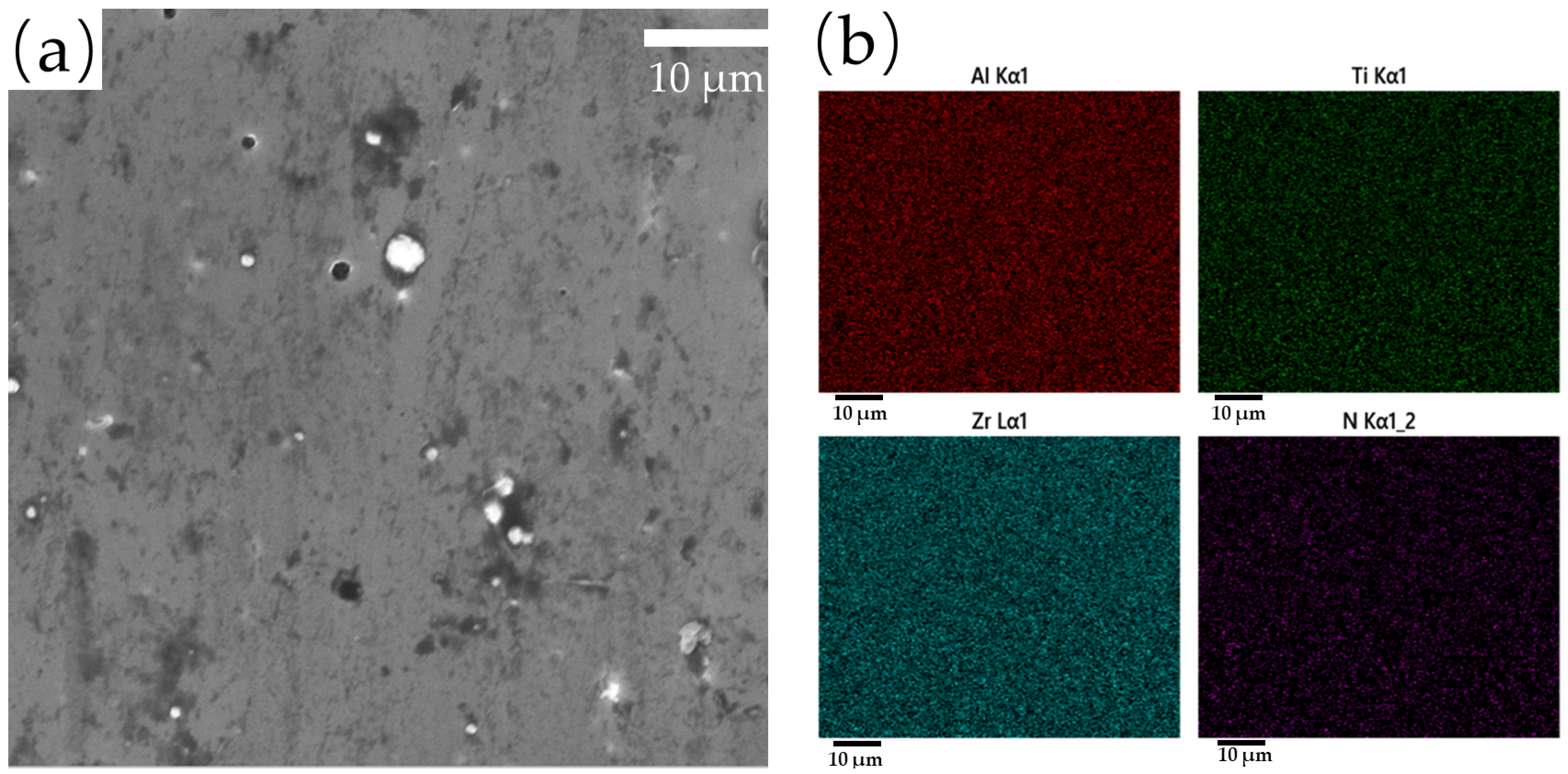
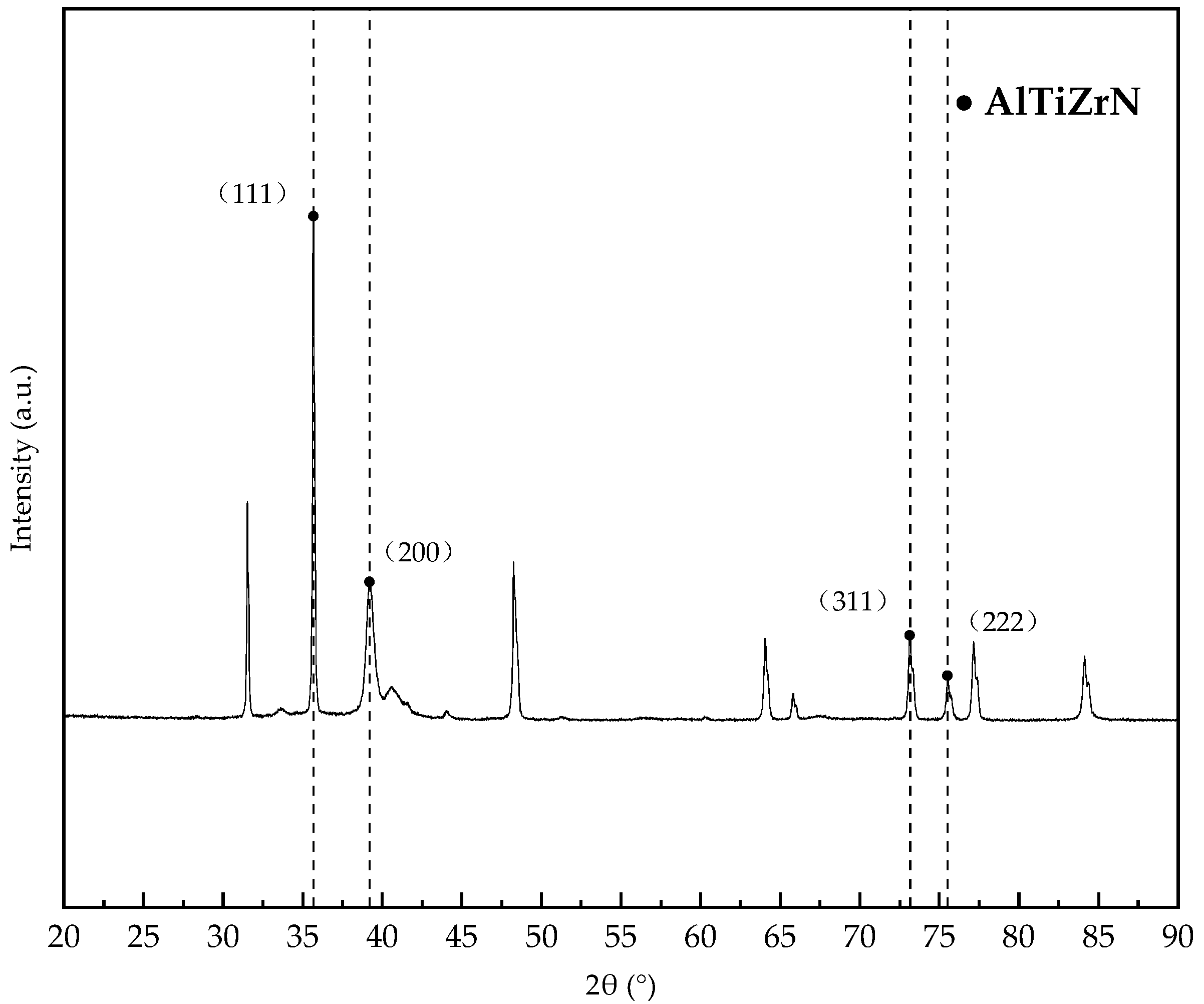
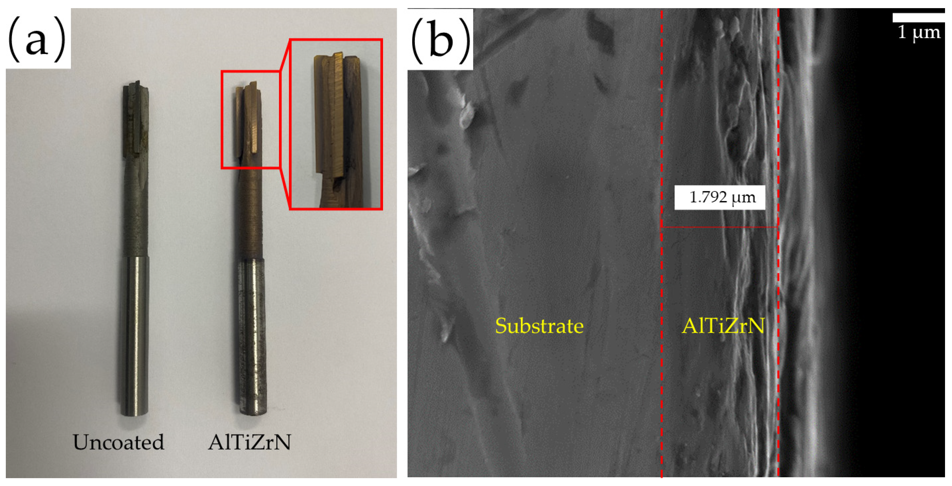
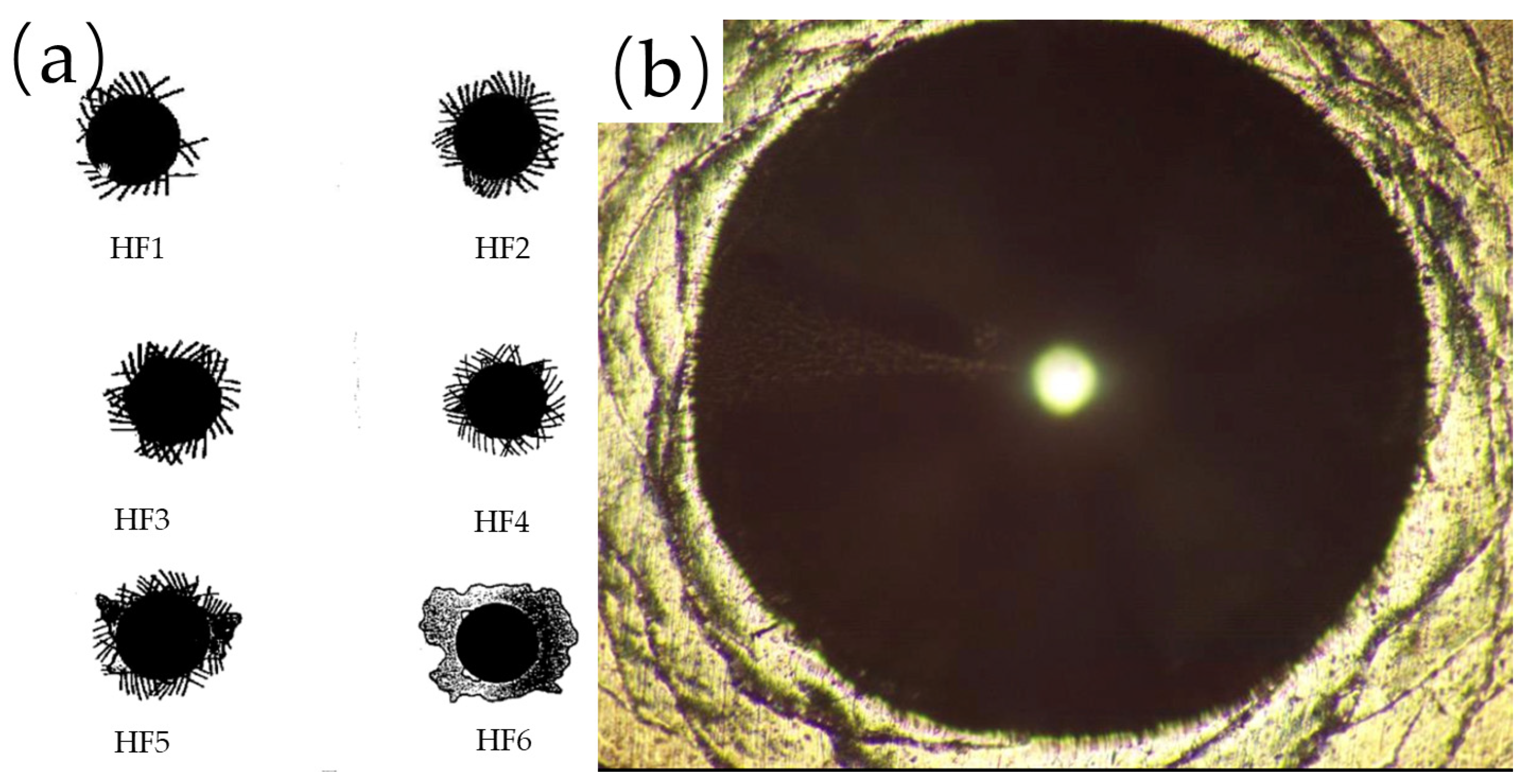
3.1. Microstructure and Mechanical Properties
3.2. Cutting Performance
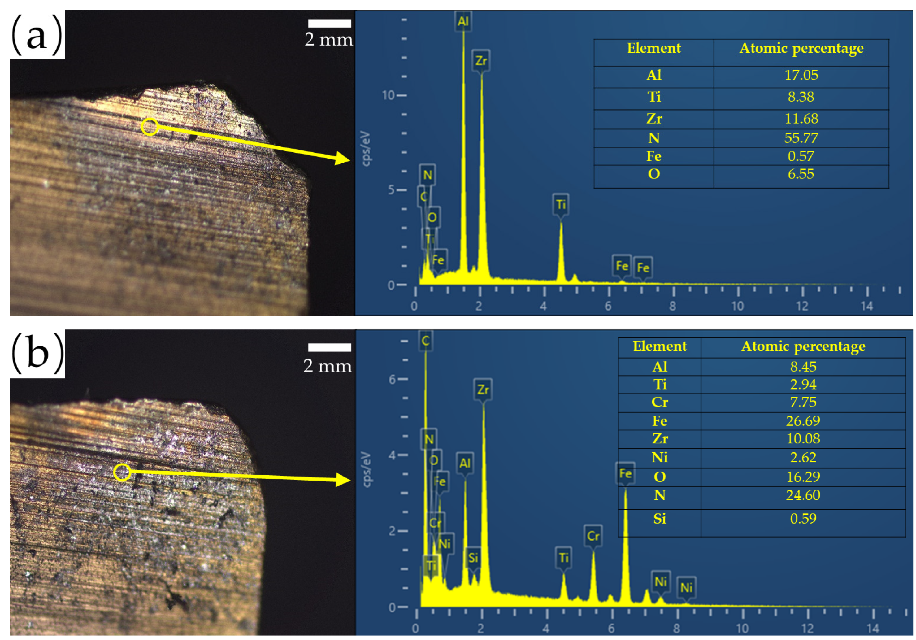
3.3. Wear Mechanism
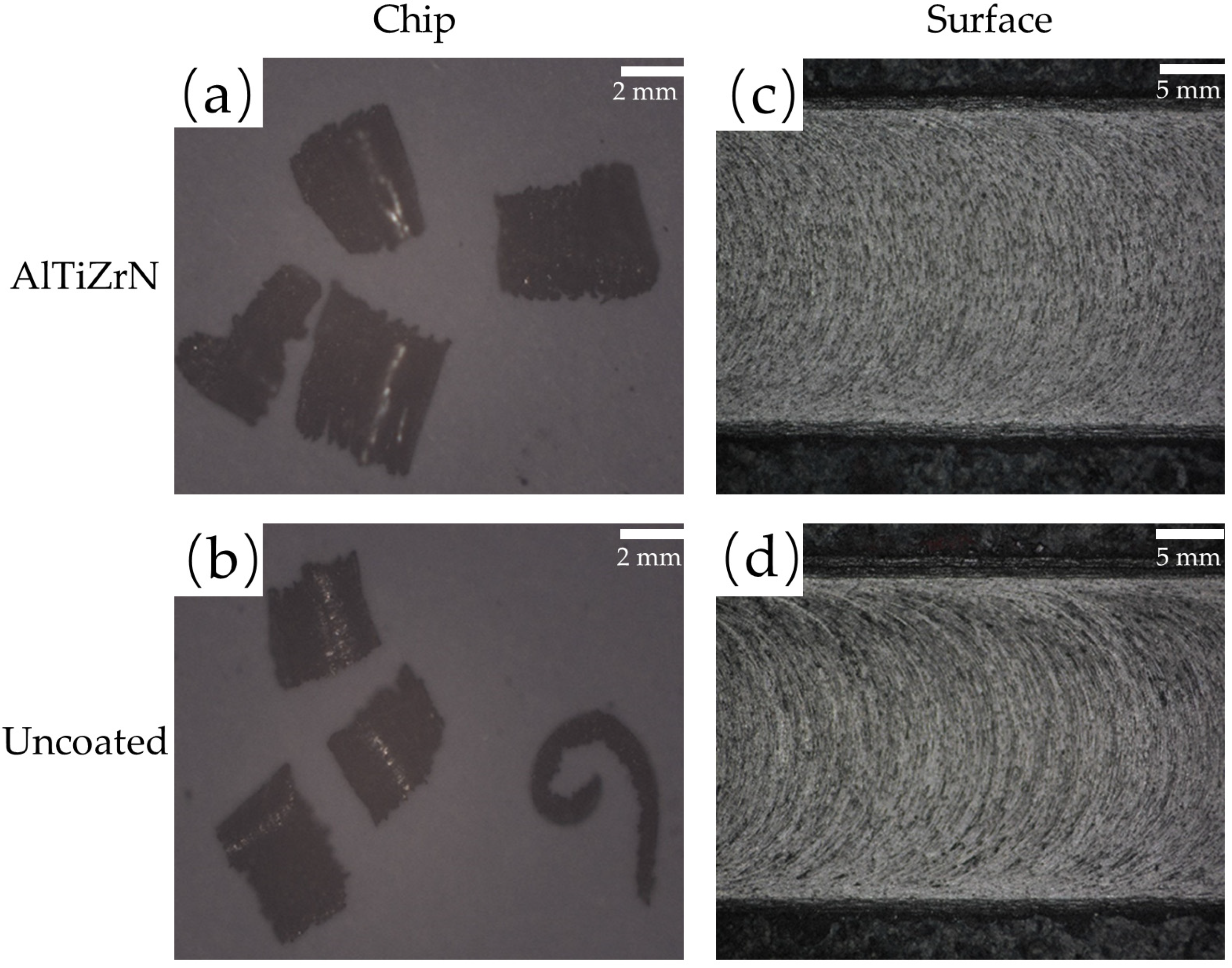
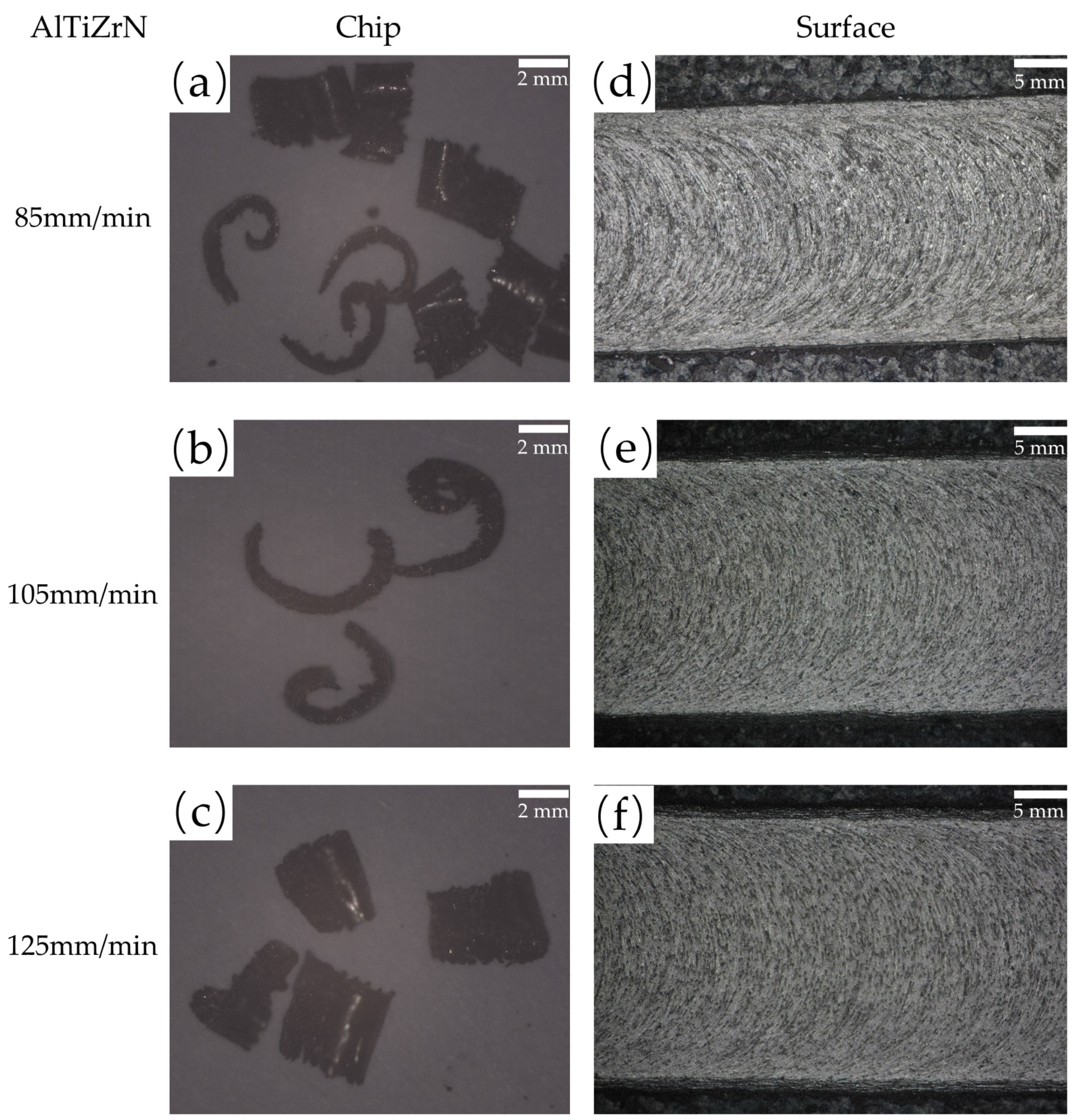
3.4. Chip Formation
4. Conclusions
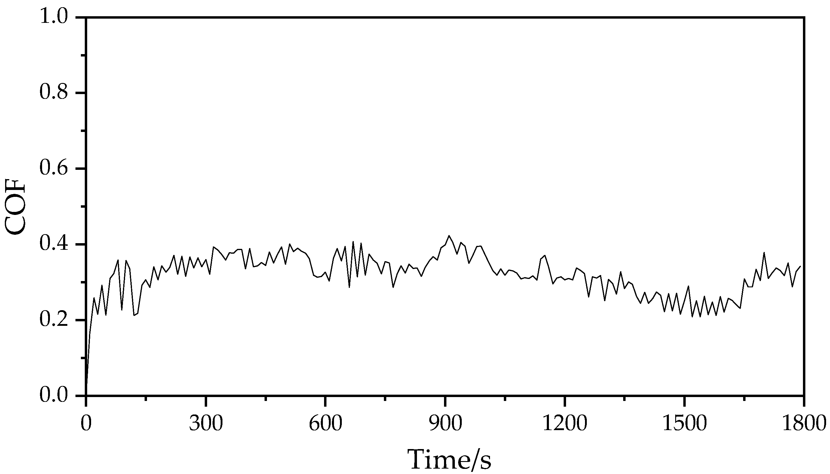
- The AlTiZrN coating presents the fcc structure of TiN; The average microhardness is 3887 HV0.05. Compared with the traditional high hardness AlTiN coating, the hardness is increased by at least 17.8%. Higher hardness will improve the wear resistance of the tool. The bonding strength between the coating and the substrate meets the standard HF3 and is up to the requirements. The COF of the coating is about 0.32. Compared with AlTiN, AlCrN, and other coatings, the COF is smaller, and the cutting performance is better.
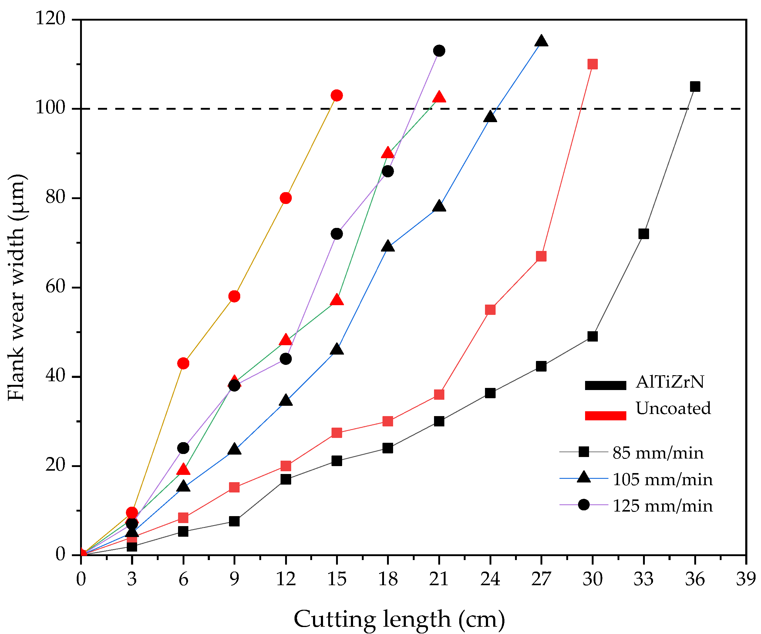
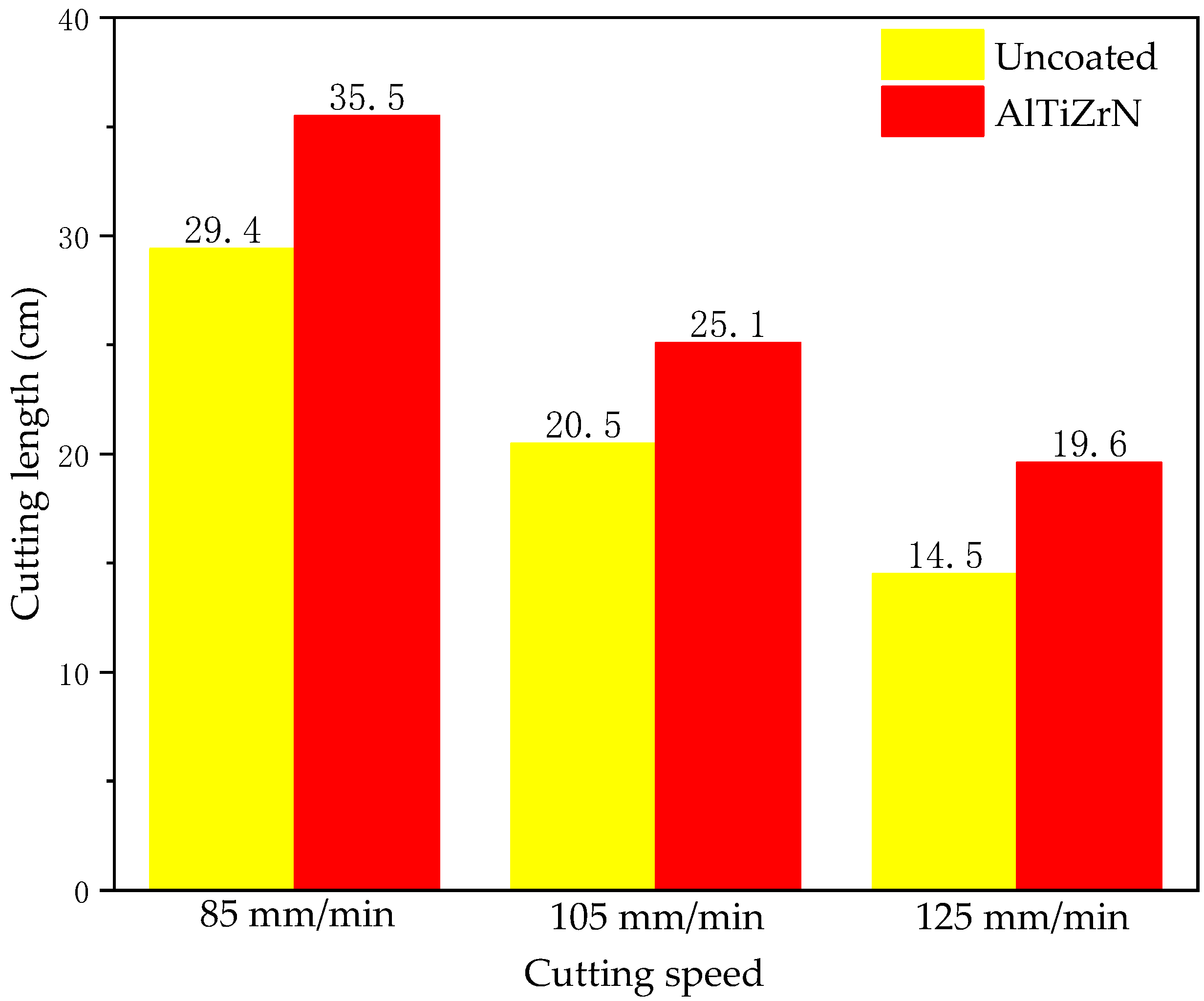
- The AlTiZrN coating can significantly improve the life of the cemented-carbide tool. At the cutting speeds of 85, 105, and 125 mm/min, the lives of the AlTiZrN-coated tools are increased by 20.7%, 22.4%, and 35.2%, respectively, compared with uncoated tools. Under the same cutting condition, AlTiZrN-coated tools have better cutting and chip-breaking performance than uncoated tools. With the increase in cutting speed, the workpiece chips produced by the AlTiZrN-coated tools are smaller and more uniform, and the scratches on the machined surface are smoother. Therefore, at a higher cutting speed, the AlTiZrN-coated tools have more advantages in the life and cutting performance than that of the uncoated tools.
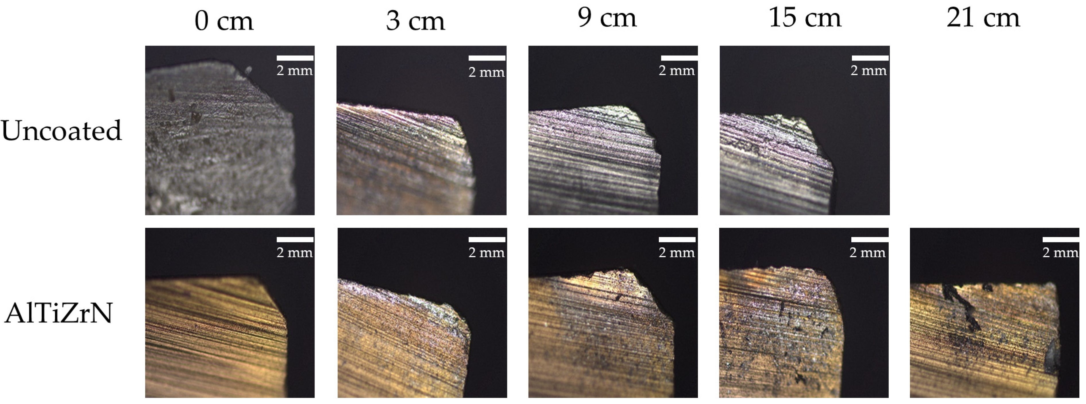
- During the cutting process, the wear mechanisms of the AlTiZrN-coated tools mainly include friction, oxidation, and bonding, while oxidation and bonding wear are the main wear mechanisms in the later stage of wear. The main wear mechanisms of the AlTiN- and TiAlSiN-coated tools include bonding, diffusion, oxidation, and cracks. In contrast, the AlTiZrN-coated tools have more advantages in terms of wear.
Author Contributions
Funding
Institutional Review Board Statement
Informed Consent Statement
Data Availability Statement
Conflicts of Interest
References
- Fortini, A.; Suman, A.; Vulpio, A.; Merlin, M.; Pinelli, M. Microstructural and Erosive Wear Characteristics of a High Chromium Cast Iron. Coatings 2021, 11, 490. [Google Scholar] [CrossRef]
- Deng, J.; Zhou, J.; Zhang, H.; Pei, Y. Wear mechanisms of cemented carbide tools in dry cutting of precipitation hardening semi-austenitic stainless steels. Wear 2011, 270, 520–527. [Google Scholar] [CrossRef]
- Fan, Y.; Hao, Z.; Zheng, M. Wear characteristics of cemented carbide tool in dry-machining Ti-6Al-4V. Mach. Sci. Technol. 2016, 20, 249–261. [Google Scholar] [CrossRef]
- Huang, Y.; Chou, Y.K.; Liang, S.Y. CBN tool wear in hard turning: A survey on research progresses. Int. J. Adv. Manuf. Technol. 2007, 35, 443–453. [Google Scholar] [CrossRef]
- Wang, Z.; Rahman, M.; Wong, Y. Tool wear characteristics of binderless CBN tools used in high-speed milling of titanium alloys. Wear 2005, 258, 752–758. [Google Scholar] [CrossRef]
- Kumar, P.; Chauhan, S.R.; Pruncu, C.I.; Gupta, M.K.; Pimenov, D.Y.; Mia, M.; Gill, H.J. Influence of Different Grades of CBN Inserts on Cutting Force and Surface Roughness of AISI H13 Die Tool Steel during Hard Turning Operation. Materials 2019, 12, 177. [Google Scholar] [CrossRef] [PubMed] [Green Version]
- Guo, C.; Wang, A.; Wang, Z.; Chen, H. Study on Optimization of cutting tools and cutting parameters in cutting high chromium cast iron. Mod. Manuf. Eng. 2009, 10, 69–71. [Google Scholar] [CrossRef]
- Fan, Q.; Lin, J.; Wang, T. Latest research progress of tool coating materials. Surf. Technol. 2022, 51, 1–19. [Google Scholar] [CrossRef]
- Qin, Z.; Xian, G.; Zhao, H.; Zheng, Y.; Fan, H.; Wang, J. Research status and future development of TiCN coatings deposited on cutting tools. Surf. Technol. 2016, 45, 125–133. [Google Scholar] [CrossRef]
- Shen, T.; Zhu, L. Comparison of microstructure and properties between TiN/TiCN/Al2O3/TiN and TiN/TiCN/Al2O3/TiCNO multilayer coatings. Surf. Technol. 2020, 49, 141–148. [Google Scholar] [CrossRef]
- Li, Y.; Chen, X.; Xu, Y.; Lin, J.; Gao, Y.; Wen, G. Research on growth way of Al2O3 and TiCN coating on cemented carbide. Cem. Carbide 2015, 32, 147–154. [Google Scholar]
- Alamgir, A.; Bogatov, A.; Jõgiaas, T.; Viljus, M.; Raadik, T.; Kübarsepp, J.; Sergejev, F.; Lümkemann, A.; Kluson, J.; Podgursky, V. High-Temperature Oxidation Resistance and Tribological Properties of Al2O3/ta-C. Coat. Coat. 2022, 12, 547. [Google Scholar] [CrossRef]
- Wei, S.; Lu, P.; Lin, R. Surface coating tools of TiAlN technology application to machining. Eng. J. Wuhan Univ. 2014, 47, 703–706. [Google Scholar]
- Claver, A.; Randulfe, J.J.; Palacio, J.F.; Fernández de Ara, J.; Almandoz, E.; Montalá, F.; Colominas, C.; Cot, V.; Garcia, J.A. Improved Adhesion and Tribological Properties of AlTiN-TiSiN Coatings Deposited by DCMS and HiPIMS on Nitrided Tool Steels. Coatings 2021, 11, 1175. [Google Scholar] [CrossRef]
- Gil, D.; Veiga, F.; Pereira, O.; Lopez De Lacalle, L.N. Threading Performance of Different Coatings for High Speed Steel Tapping. Coatings 2020, 10, 464. [Google Scholar] [CrossRef]
- Chowdhury, S.; Bose, B.; Yamamoto, K.; Veldhuis, S.C. Effect of Interlayer Thickness on Nano-Multilayer Coating Performance during High Speed Dry Milling of H13 Tool Steel. Coatings 2019, 9, 737. [Google Scholar] [CrossRef] [Green Version]
- Wang, R.; Yang, H.; Guo, Z.; Wei, S.; Lin, R. Study on the Cutting Performance of CrN/AlCrN-Coated Carbide PCB Milling Cutter. Coatings 2022, 12, 556. [Google Scholar] [CrossRef]
- De Almeida, E.A.S.; Milan, J.C.G.; da Costa, C.E.; Binder, C.; de Mello, J.D.B.; Costa, H.L. Combined Use of Surface Texturing, Plasma Nitriding and DLC Coating on Tool Steel. Coatings 2021, 11, 201. [Google Scholar] [CrossRef]
- Grigoriev, S.N.; Volosova, M.A.; Fedorov, S.V.; Migranov, M.S.; Mosyanov, M.; Gusev, A.; Okunkova, A.A. The Effectiveness of Diamond-like Carbon a-C:H:Si Coatings in Increasing the Cutting Capability of Radius End Mills When Machining Heat-Resistant Nickel Alloys. Coatings 2022, 12, 206. [Google Scholar] [CrossRef]
- Zheng, S.; Sun, D. Experimental study on cutting performance and wear resistance of DLC coated milling cutter. J. Chongqing Univ. Sci. Technol. 2021, 23, 50–53. [Google Scholar] [CrossRef]
- Ekroth, M.; Frykholm, R.; Lindholm, M.; Andrén, H.-O.; Ågren, J. Gradient zones in WC-Ti(C,N)-Co-based cemented carbides: Experimental study and computer simulations. Acta. Mater. 2000, 48, 2177–2185. [Google Scholar] [CrossRef]
- Vereschaka, A.; Milovich, F.; Andreev, N.; Sitnikov, N.; Alexandrov, I.; Muranov, A.; Mikhailov, M.; Tatarkanov, A. Efficiency of Application of (Mo, Al)N-Based Coatings with Inclusion of Ti, Zr or Cr during the Turning of Steel of Nickel-Based Alloy. Coatings 2021, 11, 1271. [Google Scholar] [CrossRef]
- Wu, J.; Li, Z.; Peng, L.; Yong, Y.; Zhang, J. Effect of nitrogen partial pressure on the structure and color of ZrN films. Vacuum 2021, 58, 57–62. [Google Scholar] [CrossRef]
- Zhang, J.; Peng, L.; Wang, X.; Liu, D.; Wang, N. Effects of Zr/(Zr+Ti) Molar Ratio on the Phase Structure and Hardness of TixZr1−xN Films. Coatings 2021, 11, 1342. [Google Scholar] [CrossRef]
- Yan, X.; Zhang, J.; Yu, Y. Deposition Process and Properties of TiN and ZrN Films Coated on Stainless Steel Root Canal Files. Surf. Technol. 2019, 48, 294–301. [Google Scholar] [CrossRef]
- Wei, Y.; Hou, J.; Jiang, Z.; Tian, X. Research status of removal methods for macroparticles defects in arc ion plating process. Hot Work. Technol. 2016, 45, 28–32. [Google Scholar] [CrossRef]
- Wei, Y.Q.; Li, C.W.; Gong, C.Z.; Tian, X.-B.; Yang, S.-Q. Microstructure and mechanical properties of TiN/TiAlN multilayer coatings deposited by arc ion plating with separate targets. Trans. Nonferrous Met. Soc. China 2011, 21, 1068–1073. [Google Scholar] [CrossRef]
- Dong, X.; Zhang, Z.; Liang, H.; Bian, C.; Huang, N.; Huang, X. Research on reducing macroparticles during arc ion plating. Heat Treat. Met. 2012, 37, 125–127. [Google Scholar] [CrossRef]
- Rui, W.; Mei, H.-J.; Li, R.-S.; Zhang, Q.; Zhang, T.-F.; Wang, Q.-M. Friction and wear behavior of AlTiN-Coated carbide balls against SKD11 hardened steel at elevated temperatures. Acta Metall. Sin. 2018, 31, 1073–1083. [Google Scholar] [CrossRef] [Green Version]
- Wu, Y.; Wang, L.; Chen, Q.; Huang, B.; Zhang, E.; Zhou, Q.; Zheng, G. Properties and milling performance of AlTiN and TiAlSiN coatings prepared by cathodic arc. China Ceram. 2019, 55, 29–35. [Google Scholar] [CrossRef]
- Liu, J.; Zhu, S.-S.; Deng, X.; Liu, J.-Y.; Wang, Z.-P.; Qu, Z. Cutting performance and wear behavior of AITiN-and TiAlSiN-Coated carbide tools during dry milling of Ti-6Al-4V. Acta Metall. Sin. 2020, 33, 459–470. [Google Scholar] [CrossRef] [Green Version]
- Zhang, C. Investigation on Influence Factors and Distribution Law of Hardness of TiAlZrN Film System. Master’s Thesis, Shenyang University, Shenyang, China, 2021. [Google Scholar]
- Li, C.; Holec, D.; Du, Y.; Mayrhofer, P.H. Influence of Zr on structure, mechanical and thermal properties of Ti-Al-N. Thin Solid Film. 2011, 519, 5503–5510. [Google Scholar] [CrossRef] [Green Version]
- Warcholinski, B.; Gilewicz, A.; Myslinski, P.; Dobruchowska, E.; Murzynski, D. Structure and properties of AlCrN coatings deposited using cathodic arc evaporation. Coatings 2020, 10, 793. [Google Scholar] [CrossRef]
- Al-Bukhaiti, M.A.; Al-Hatab, K.A.; Tillmann, W.; Hoffman, F.; Sprute, T. Tribological and mechanical properties of Ti/TiAlN/TiAlCN nanoscale multilayer PVD coatings deposited on AISI H11 hot work tool steel. Appl. Surf. Sci. 2014, 318, 180–190. [Google Scholar] [CrossRef]
- Liu, H.; Wang, M.; Liu, X. Research on wear performance of composite coating tool drilling Inconel 718. Agric. Equip. Veh. Eng. 2022, 60, 65–69. [Google Scholar]


| Brand | Chemical Composition | |
|---|---|---|
| WC | Co | |
| YG8 | 92 | 8 |
| Brand | Physical and Mechanical Properties | ||||
|---|---|---|---|---|---|
| Hardness (HRA) | Flexural Strength/MPa | Compressive Strength/MPa | Modulus of Elasticity/GPa | Thermal Conductivity/(W/mK) | |
| YG8 | 89 | 1500 | 4470 | 600~610 | 75.36 |
| Brand | C | Mn | Si | Ni | Cr | Mo | Cu | P | S |
|---|---|---|---|---|---|---|---|---|---|
| KmTBCr12 | 2.0–3.3 | ≤2.0 | ≤1.5 | ≤2.5 | 11.0–14.0 | ≤3.0 | ≤1.2 | ≤0.10 | ≤0.06 |
| Parameters | Values |
|---|---|
| Tool diameter (mm) | 8 |
| Milling flute number | 4 |
| Milling method | Forward milling |
| Cutting speed (mm/min) | 85, 105, 125 |
| Feed rate (mm/r) | 0.2 |
| Depth of cut (mm) | 0.2 |
| Cutting fluid | None |
| Diffraction Peak | 2θ | FWHM | Lattice Size (Å) |
|---|---|---|---|
| (111) | 35.669° | 0.157 | 687 |
| (220) | 39.167° | 0.542 | 158 |
| (311) | 73.147° | 0.234 | 467 |
| (222) | 75.530° | 0.246 | 446 |
| Coating | Chemical Composition (at.%) | Thickness (μm) | Hardness (HV0.05) | COF | |||
|---|---|---|---|---|---|---|---|
| Al | Ti | Zr | N | ||||
| AlTiZrN | 18.55 | 11.28 | 23.17 | 47.00 | 1.792 | 3887 | 0.32 |
Publisher’s Note: MDPI stays neutral with regard to jurisdictional claims in published maps and institutional affiliations. |
© 2022 by the authors. Licensee MDPI, Basel, Switzerland. This article is an open access article distributed under the terms and conditions of the Creative Commons Attribution (CC BY) license (https://creativecommons.org/licenses/by/4.0/).
Share and Cite
Yang, H.; Wang, R.; Guo, Z.; Lin, R.; Wei, S.; Weng, J. Cutting Performance of Multicomponent AlTiZrN-Coated Cemented Carbide (YG8) Tools during Milling of High-Chromium Cast Iron. Coatings 2022, 12, 686. https://doi.org/10.3390/coatings12050686
Yang H, Wang R, Guo Z, Lin R, Wei S, Weng J. Cutting Performance of Multicomponent AlTiZrN-Coated Cemented Carbide (YG8) Tools during Milling of High-Chromium Cast Iron. Coatings. 2022; 12(5):686. https://doi.org/10.3390/coatings12050686
Chicago/Turabian StyleYang, Hu, Renxin Wang, Ziming Guo, Rongchuan Lin, Shasha Wei, and Jianchun Weng. 2022. "Cutting Performance of Multicomponent AlTiZrN-Coated Cemented Carbide (YG8) Tools during Milling of High-Chromium Cast Iron" Coatings 12, no. 5: 686. https://doi.org/10.3390/coatings12050686
APA StyleYang, H., Wang, R., Guo, Z., Lin, R., Wei, S., & Weng, J. (2022). Cutting Performance of Multicomponent AlTiZrN-Coated Cemented Carbide (YG8) Tools during Milling of High-Chromium Cast Iron. Coatings, 12(5), 686. https://doi.org/10.3390/coatings12050686