
Uses of Scanning Electrochemical Microscopy (SECM) for the Characterization with Spatial and Chemical Resolution of Thin Surface Layers and Coating Systems Applied on Metals: A Review


Abstract
1. Introduction
2. Experimental Design for SECM Operation
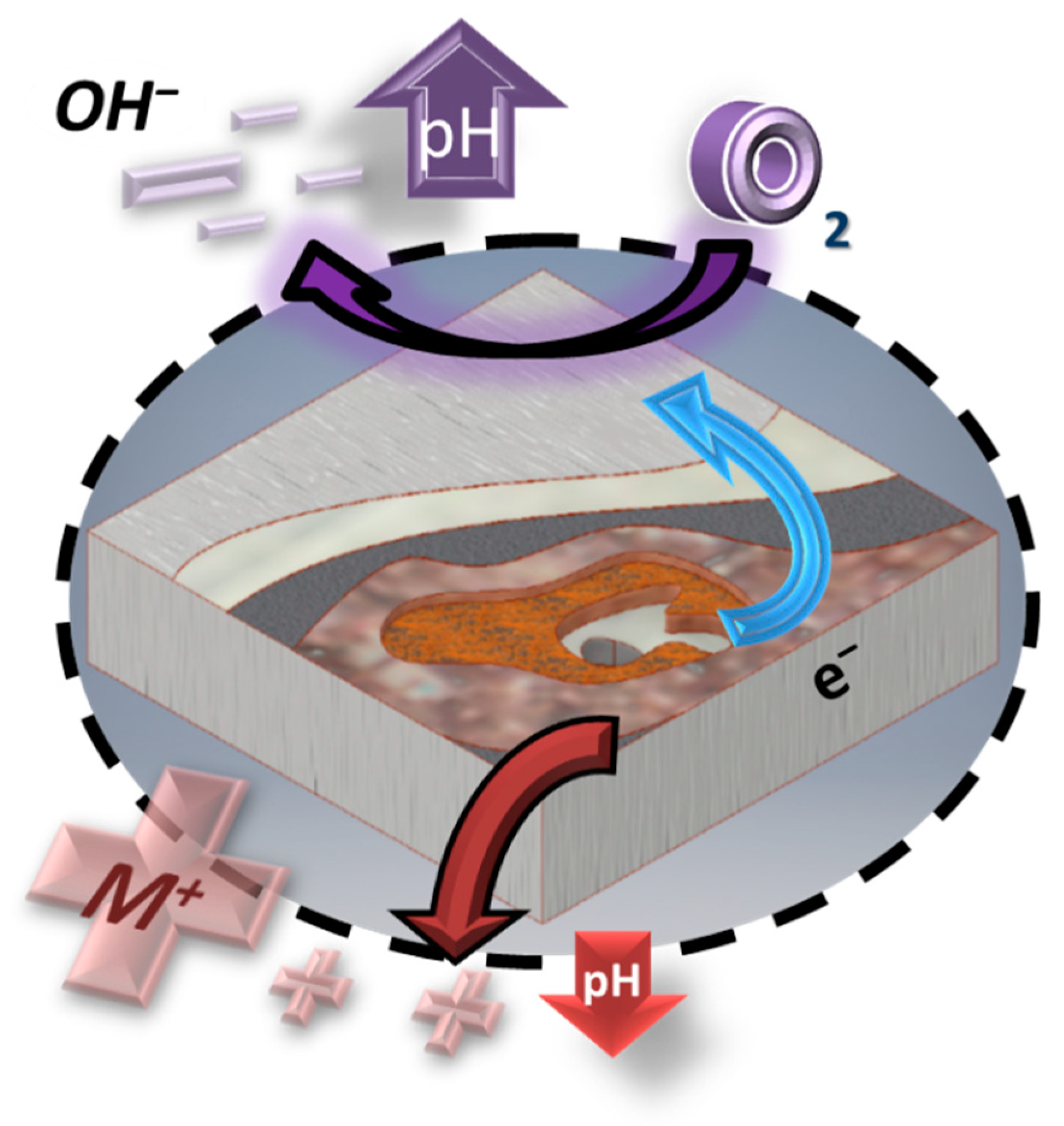
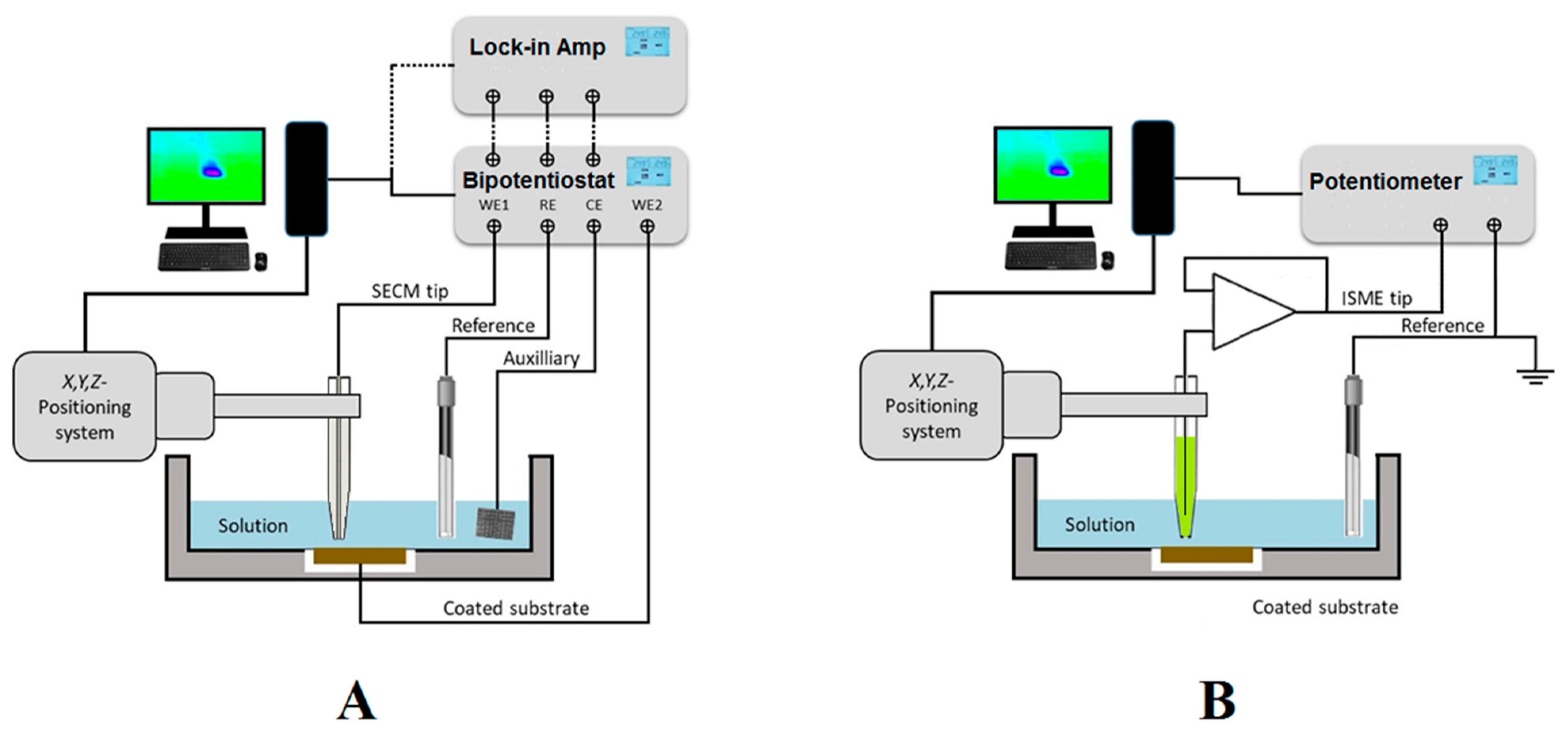
2.1. SECM Instrumentation
2.2. Tips Used for Amperometric Operation
2.3. Redox Mediators
- The nature of the sample studied;
- The nature of the mediator (chemical stability, redox potential, photostability, toxicity, thermal stability, and solubility in the solution to be tested); and
- The mode of operation to use in SECM.
2.4. Tips Used for Potentiometric Operation
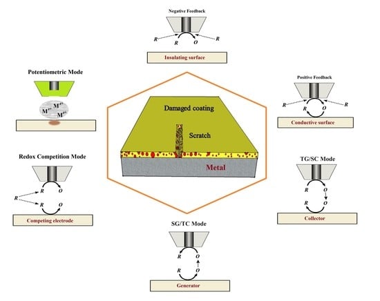
3. Operation Modes
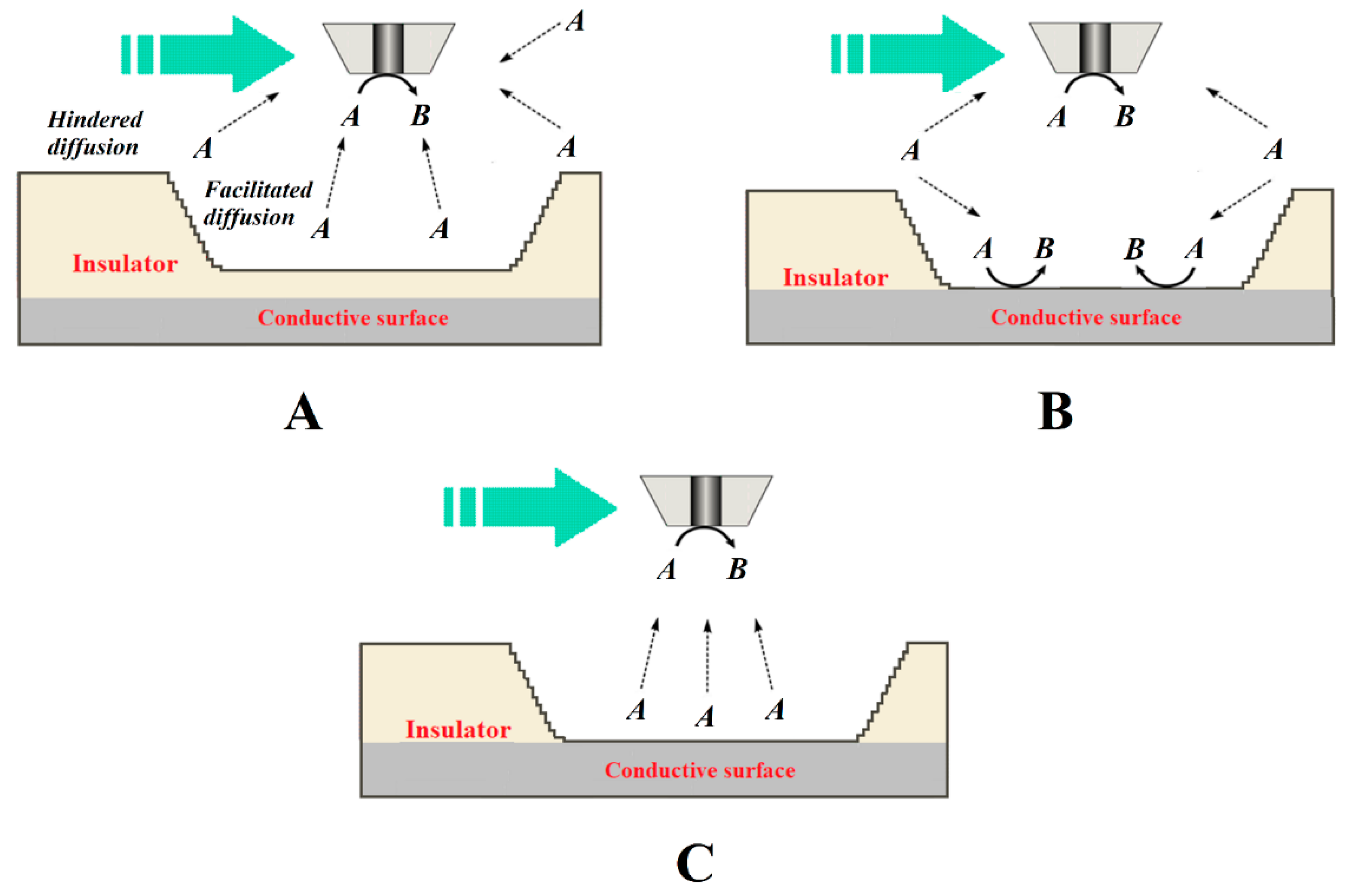
3.1. Feedback Modes
3.2. Generation-Collection Modes
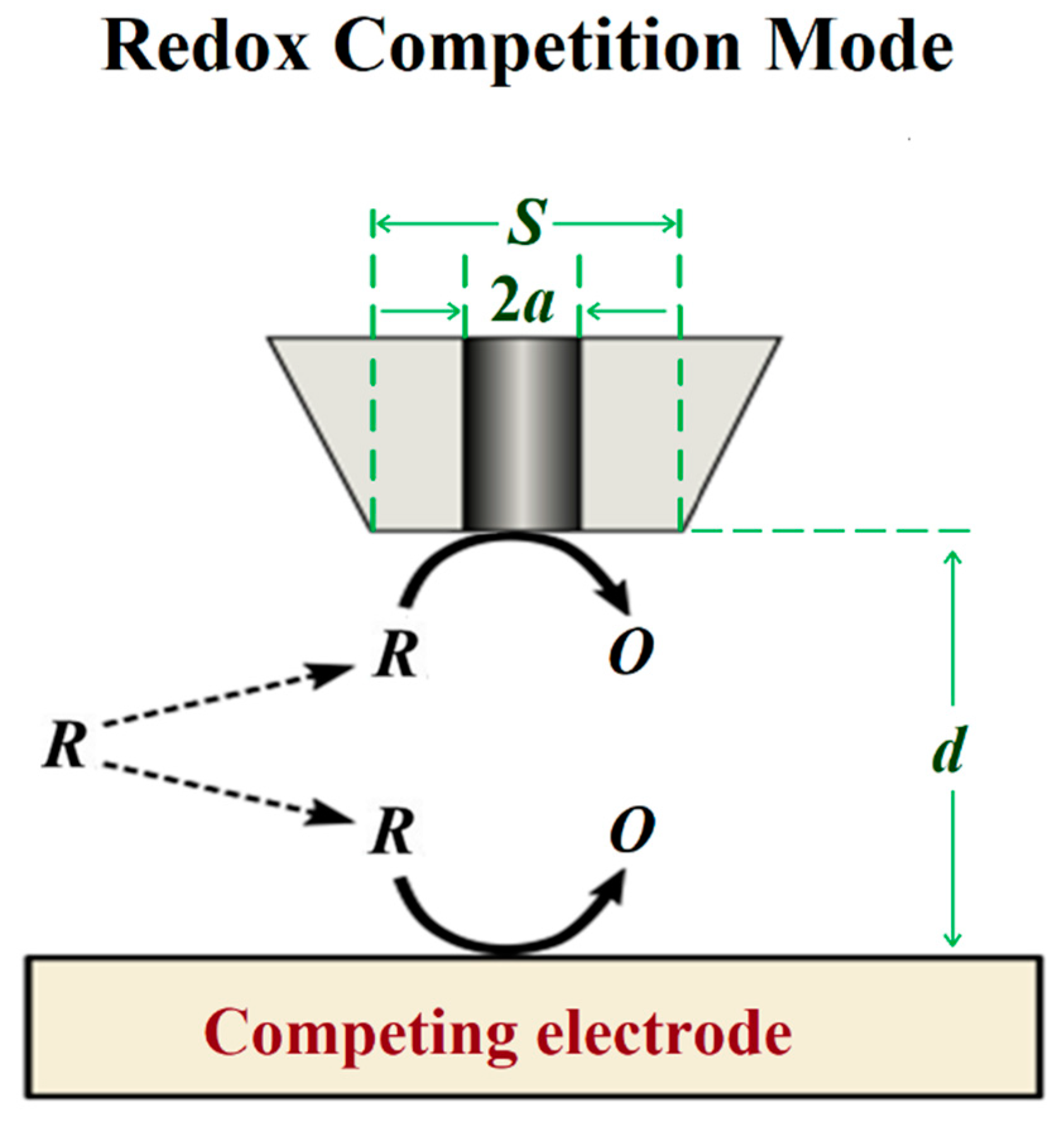
3.3. Redox Competition Mode
3.4. Combined Operation Modes
4. Concluding Remarks
Author Contributions
Funding
Institutional Review Board Statement
Informed Consent Statement
Data Availability Statement
Acknowledgments
Conflicts of Interest
References
- González-García, Y.; Santana, J.J.; González-Guzmán, J.; Izquierdo, J.; González, S.; Souto, R.M. Scanning electrochemical microscopy for the investigation of localized degradation processes in coated metals. Prog. Org. Coat. 2010, 69, 110–117. [Google Scholar] [CrossRef]
- Blaiszik, B.J.; Kramer, S.L.B.; Olugebefola, S.C.; Moore, J.S.; Sottos, N.R.; White, S.R. Self-healing polymers and composites. Annu. Rev. Mater. 2010, 40, 179–211. [Google Scholar] [CrossRef]
- Stankiewicz, A.; Szczygieł, I.; Szczygieł, B. Self-healing coatings in anti-corrosion applications. J. Mater. Sci. 2013, 48, 8041–8051. [Google Scholar] [CrossRef]
- Montemor, M.F. Functional and smart coatings for corrosion protection: A review of recent advances. Surf. Coat. Technol. 2014, 258, 17–37. [Google Scholar] [CrossRef]
- Pistorius, P.C.; Burstein, G.T. Metastable pitting corrosion of stainless steel and the transition to stability. Phil. Trans. Roy. Soc. London A 1992, 341, 531–559. [Google Scholar]
- Tan, Y. Sensing localised corrosion by means of electrochemical noise detection and analysis. Sens. Actuator B-Chem. 2010, 139, 688–698. [Google Scholar] [CrossRef]
- Suter, T.; Böhni, H. A new microelectrochemical method to study pit initiation on stainless steels. Electrochim. Acta 1997, 42, 3275–3280. [Google Scholar] [CrossRef]
- Gupta, R.K.; Sukiman, N.L.; Cavanaugh, M.K.; Hinton, B.R.W.; Hutchinson, C.R.; Birbilis, N. Metastable pitting characteristics of aluminium alloys measured using current transients during potentiostatic polarisation. Electrochim. Acta 2012, 66, 245–254. [Google Scholar] [CrossRef]
- Martin, F.A.; Bataillon, C.; Cousty, J. In situ AFM detection of pit onset location on a 304L stainless steel. Corros. Sci. 2008, 50, 84–92. [Google Scholar] [CrossRef]
- Birbilis, N.; Meyer, K.; Muddle, B.C.; Lynch, S.P. In situ measurement of corrosion on the nanoscale. Corros. Sci. 2009, 51, 1569–1572. [Google Scholar] [CrossRef]
- Maurice, V.; Marcus, P. Passive films at the nanoscale. Electrochim. Acta 2012, 84, 129–138. [Google Scholar] [CrossRef]
- Lillard, R.S. Scanning electrode techniques for investigating near-surface solution current densities. In Analytical Methods in Corrosion Science and Engineering; Marcus, P., Mansfeld, F., Eds.; CRC Press: Boca Raton, FL, USA, 2006; pp. 571–604. [Google Scholar]
- Jensen, M.B.; Tallman, D.E. Application of SECM to corrosion studies. In Electroanalytical Chemistry: A Series of Advances; Bard, A.J., Zoski, C., Eds.; CRC Press: Boca Raton, FL, USA, 2012; Volume 24, pp. 171–286. [Google Scholar]
- Payne, N.A.; Stephens, L.I.; Mauzeroll, J. The application of scanning electrochemical microscopy to corrosion research. Corrosion 2017, 73, 759–780. [Google Scholar] [CrossRef]
- Huang, V.M.-W.; Wu, S.–H.; Orazem, M.E.; Pébère, N.; Tribollet, B.; Vivier, V. Local electrochemical impedance spectroscopy: A review and some recent developments. Electrochim. Acta 2011, 56, 8048–8057. [Google Scholar] [CrossRef]
- Engstrom, R.C.; Pharr, C.M. Scanning electrochemical microscopy. Anal. Chem. 1989, 61, 1099A–1104A. [Google Scholar] [CrossRef]
- Bard, A.J.; Fan, F.R.F.; Kwak, J.; Lev, O. Scanning electrochemical microscopy. Introduction and principles. Anal. Chem. 1989, 61, 132–138. [Google Scholar] [CrossRef]
- Polcari, D.; Dauphin-Ducharme, P.; Mauzeroll, J. Scanning electrochemical microscopy: A comprehensive review of experimental parameters from 1989 to 2015. Chem. Rev. 2016, 116, 13234–13278. [Google Scholar] [CrossRef]
- Farrokhpay, S. Application of spectroscopy and microscopy techniques in surface coatings evaluation: A review. Appl. Spectrosc. Rev. 2012, 47, 233–243. [Google Scholar] [CrossRef]
- Zoski, C.G. Review-Advances in scanning electrochemical microscopy (SECM). J. Electrochem. Soc. 2016, 163, H3088–H3100. [Google Scholar] [CrossRef]
- Izquierdo, J.; Knittel, P.; Kranz, C. Scanning electrochemical microscopy: An analytical perspective. Anal. Bioanal. Chem. 2018, 410, 307–324. [Google Scholar] [CrossRef]
- Etienne, M.; Schulte, A.; Schuhmann, W. High resolution constant-distance mode alternating current scanning electrochemical microscopy (AC-SECM). Electrochem. Commun. 2004, 6, 288–293. [Google Scholar] [CrossRef]
- Kuznetsov, V.; Maljusch, A.; Souto, R.M.; Bandarenka, A.S.; Schuhmann, W. Characterisation of localised corrosion processes using scanning electrochemical impedance microscopy. Electrochem. Commun. 2014, 4, 38–41. [Google Scholar] [CrossRef]
- Katemann, B.B.; Inchauspe, C.G.; Castro, P.A.; Schulte, A.; Calvo, E.J.; Schuhmann, W. Precursor sites for localised corrosion on lacquered tinplates visualised by means of alternating current scanning electrochemical microscopy. Electrochim. Acta 2003, 48, 1115–1121. [Google Scholar] [CrossRef]
- Eckhard, K.; Erichsen, T.; Stratmann, M.; Schuhmann, W. Frequency-dependent alternating-current scanning electrochemical microscopy (4D AC-SECM) for local visualisation of corrosion sites. Chem. Eur. J. 2008, 14, 3968–3976. [Google Scholar] [CrossRef] [PubMed]
- Eckhard, K.; Schuhmann, W.; Maciejewska, M. Determination of optimum imaging conditions in AC-SECM using the mathematical distance between approach curves displayed in the impedance domain. Electrochim. Acta 2009, 54, 2125–2130. [Google Scholar] [CrossRef]
- Pähler, M.; Santana, J.J.; Schuhmann, W.; Souto, R.M. Application of AC-SECM in Corrosion Science—Local visualisation of inhibitor films on active metals for corrosion protection. Chem. Eur. J. 2011, 17, 905–911. [Google Scholar] [CrossRef]
- Pähler, M.; Santana, J.J.; Schuhmann, W.; Souto, R.M. Investigation of copper corrosion inhibition with frequency-dependent alternating-current scanning electrochemical microscopy. ChemPlusChem 2012, 77, 707–712. [Google Scholar]
- Souto, R.M.; Socas, B.; Izquierdo, J.; Santana, J.J.; González, S. New opportunities for the study of organic films applied on metals for corrosion protection by means of alternating current scanning electrochemical microscopy. Prog. Org. Coat. 2012, 74, 371–375. [Google Scholar] [CrossRef]
- Santana, J.J.; Pähler, M.; Souto, R.M.; Schuhmann, W. Direct evidence of early blister formation in polymer-coated metals from exposure to chloride-containing electrolytes by alternating-current scanning electrochemical microscopy. Electrochim. Acta 2012, 77, 60–64. [Google Scholar] [CrossRef]
- Bandarenka, A.S.; Eckhard, K.; Maljusch, A.; Schuhmann, W. Localized electrochemical impedance spectroscopy: Visualization of spatial distributions of the key parameters describing solid/liquid interfaces. Anal. Chem. 2013, 85, 2443–2448. [Google Scholar] [CrossRef]
- Bandarenka, A.S.; Maljusch, A.; Kuznetsov, V.; Eckhard, K.; Schuhmann, W. Localized electrochemical impedance measurements for electrochemical surface science. J. Phys. Chem. C 2014, 118, 8952–8959. [Google Scholar] [CrossRef]
- Kuznetsov, V.; Estrada-Vargas, A.; Maljusch, A.; Berkes, B.B.; Bandarenka, A.S.; Souto, R.M.; Schuhmann, W. Kinetic passivation effect of localized differential aeration on brass. ChemPlusChem 2016, 81, 49–57. [Google Scholar] [CrossRef] [PubMed]
- Estrada-Vargas, A.; Bandarenka, A.; Kuznetsov, V.; Schuhmann, W. In situ characterization of ultrathin films by scanning electrochemical impedance spectroscopy. Anal. Chem. 2016, 88, 3354–3362. [Google Scholar] [CrossRef] [PubMed]
- Wang, W.; Li, W.; Song, L.; Fan, W.; Xiong, C.; Gao, X.; Zhang, X.; Liu, X. Self-healing performance of coatings containing synthetic hexamethylene diisocyanate biuret microcapsules. J. Electrochem. Soc. 2017, 164, C635–C640. [Google Scholar] [CrossRef]
- Wang, W.; Wang, H.; Zhao, J.; Wang, X.; Xiong, C.; Song, L.; Ding, R.; Han, P.; Li, W. Self-healing performance and corrosion resistance of graphene oxide-mesoporous silicon layer-nanosphere structure coating under marine alternating hydrostatic pressure. Chem. Eng. J. 2019, 361, 792–804. [Google Scholar] [CrossRef]
- Lamaka, S.V.; Souto, R.M.; Ferreira, M.G.S. In-situ visualization of local corrosion by scanning ion-selective electrode technique (SIET). In Microscopy: Science, Technology, Applications and Education; Méndez-Vilas, A., Díaz, J., Eds.; Formatex Research Center: Badajoz, Spain, 2010; Volume 3, pp. 2162–2173. [Google Scholar]
- Kiss, A.; Filotás, D.; Souto, R.M.; Nagy, G. The effect of electric field on potentiometric scanning electrochemical microscopic imaging. Electrochem. Commun. 2017, 77, 138–141. [Google Scholar] [CrossRef]
- Filotás, D.; Fernández-Pérez, B.M.; Izquierdo, J.; Kiss, A.; Nagy, L.; Nagy, G.; Souto, R.M. Improved potentiometric SECM imaging of galvanic corrosion reactions. Corros. Sci. 2017, 129, 136–145. [Google Scholar] [CrossRef]
- Filotás, D.; Fernández-Pérez, B.M.; Kiss, A.; Nagy, L.; Nagy, G.; Souto, R.M. Double barrel microelectrode assembly to prevent electrical field effects in potentiometric SECM imaging of galvanic corrosion processes. J. Electrochem. Soc. 2018, 165, C270–C277. [Google Scholar] [CrossRef]
- Marques, A.G.; Izquierdo, J.; Souto, R.M.; Simões, A.M. SECM imaging of the cut edge corrosion of galvanized steel as a function of pH. Electrochim. Acta 2015, 153, 238–245. [Google Scholar] [CrossRef]
- Filotás, D.; Izquierdo, J.; Fernández-Pérez, B.M.; Nagy, L.; Nagy, G.; Souto, R.M. Contributions of microelectrochemical scanning techniques for the efficient detection of localized corrosion processes at the cut edges of polymer-coated galvanized steel. Molecules 2022, 27, 2167. [Google Scholar] [CrossRef]
- Stulík, K.; Amatore, C.; Holub, K.; Marecek, V.; Kutner, W. Microelectrodes. Definitions, characterization, and applications (Technical report). Pure Appl. Chem. 2000, 72, 1483–1492. [Google Scholar] [CrossRef]
- Izquierdo, J.; Nagy, L.; Varga, Á.; Santana, J.J.; Nagy, G.; Souto, R.M. Spatially resolved measurement of electrochemical activity and pH distributions in corrosion processes by scanning electrochemical microscopy using antimony microelectrode tips. Electrochim. Acta 2011, 56, 8846–8850. [Google Scholar] [CrossRef]
- Zhu, Z.J.; Ye, Z.N.; Zhang, J.Q.; Cao, F.H. Novel dual Pt-Pt-IrOx ultramicroelectrode for pH imaging using SECM in both potentiometric and amperometric modes. Electrochem. Commun. 2018, 88, 47–51. [Google Scholar] [CrossRef]
- Lefrou, C.; Cornut, R. Analytical expressions for quantitative scanning electrochemical microscopy (SECM). Chem. Phys. Chem. 2010, 11, 547–556. [Google Scholar] [CrossRef] [PubMed]
- Cortés-Salazar, F.; Deng, H.; Peljo, P.; Pereira, C.M.; Kontturi, K.; Girault, H.H. Parylene C coated microelectrodes for scanning electrochemical microscopy. Electrochim. Acta 2013, 110, 22–29. [Google Scholar] [CrossRef]
- Tefashe, U.M.; Dauphin-Ducharme, P.; Danaie, M.; Cano, Z.P.; Kish, J.R.; Botton, G.A.; Mauzeroll, J. Localized corrosion behavior of AZ31B magnesium alloy with an electrodeposited poly (3,4-ethylenedioxythiophene) coating. J. Electrochem. Soc. 2015, 162, C536–C544. [Google Scholar] [CrossRef]
- Combellas, C.; Kanoufi, F.; Mazouzi, D.; Thiébault, A. Surface modification of halogenated polymers: 5. Localized electroless deposition of metals on poly(tetrafluoroethylene) surfaces. J. Electroanal. Chem. 2003, 556, 43–52. [Google Scholar] [CrossRef]
- Grisotto, F.; Ghorbal, A.; Goyer, C.; Charlier, J.; Palacin, S. Direct SECM localized electrografting of vinylic monomers on a conducting substrate. Chem. Mater. 2011, 23, 1396–1405. [Google Scholar] [CrossRef]
- Molina, J.; Zille, A.; Fernández, J.; Souto, A.P.; Bonastre, J.; Cases, F. Conducting fabrics of polyester coated with polypyrrole and doped with graphene oxide. Synth. Met. 2015, 204, 110–121. [Google Scholar] [CrossRef]
- Borgwarth, K.; Ebling, D.; Heinze, J. Applications of scanning ultra micro electrodes for studies on surface conductivity. Electrochim. Acta 1995, 40, 1455–1460. [Google Scholar] [CrossRef]
- Holt, K.B.; Hu, J.; Foord, J.S. Fabrication of boron-doped diamond ultramicroelectrodes for use in scanning electrochemical microscopy experiments. Anal. Chem. 2007, 79, 2556–2561. [Google Scholar] [CrossRef]
- Varvara, S.; Caniglia, G.; Izquierdo, J.; Bostan, R.; Gaina, L.; Souto, R.M. Multiscale electrochemical analysis of the corrosion control of bronze in simulated acid rain by horse-chestnut (Aesculus hippocastanum L.) extract as green inhibitor. Corros. Sci. 2020, 165, 108381. [Google Scholar] [CrossRef]
- Zhou, J.; Campbell, C.; Heller, A.; Bard, A.J. Scanning electrochemical microscopy. 44. Imaging of horseradish peroxidase immobilized on insulating substrates. Anal. Chem. 2002, 74, 4007–4010. [Google Scholar] [CrossRef] [PubMed]
- Zhang, J.; Barker, A.L.; Unwin, P.R. Microelectrochemical studies of charge transfer at the interface between two immiscible electrolyte solutions: Electron transfer from decamethyl ferrocene to aqueous oxidants. J. Electroanal. Chem. 2000, 483, 95–107. [Google Scholar] [CrossRef]
- Seegmiller, J.C.; Buttry, D.A. A SECM study of heterogeneous redox activity at AA2024 surfaces. J. Electrochem. Soc. 2003, 150, 413–418. [Google Scholar] [CrossRef]
- Quinto, M.; Jenekhe, S.A.; Bard, A.J. Polymer films on electrodes. 30. Electrochemistry and scanning electrochemical microscopy characterization of benzimidazolebenzophenanthroline-type ladder (BBL) and semiladder (BBB) polymer films. Chem. Mater. 2001, 13, 2824–2832. [Google Scholar] [CrossRef]
- Sánchez-Sánchez, C.M.; Rodríguez-López, J.; Bard, A.J. Scanning electrochemical microscopy. 60. Quantitative calibration of the SECM substrate generation/tip collection mode and its use for the study of the oxygen reduction mechanism. Anal. Chem. 2008, 80, 3254–3260. [Google Scholar] [CrossRef]
- Mandler, D. A new approach to the high resolution electrodeposition of metals via the feedback mode of the scanning electrochemical microscope. J. Electrochem. Soc. 1990, 137, 1079–1086. [Google Scholar] [CrossRef]
- Lee, C.; Bard, A.J. Scanning electrochemical microscopy. Application to polymer and thin metal oxide films. Anal. Chem. 1990, 62, 1906–1913. [Google Scholar] [CrossRef]
- Horrocks, B.R.; Schmidtke, D.; Heller, A.; Bard, A.J. Scanning electrochemical microscopy. 24. Enzyme ultramicroelectrodes for the measurement of hydrogen peroxide at surfaces. Anal. Chem. 1993, 65, 3605–3614. [Google Scholar] [CrossRef]
- Basame, S.B.; White, H.S. Scanning electrochemical microscopy of metal/metal oxide electrodes. Analysis of spatially localized electron-transfer reactions during oxide growth. Anal. Chem. 1999, 71, 3166–3170. [Google Scholar] [CrossRef]
- Basame, S.B.; White, H.S. Scanning electrochemical microscopy of native titanium oxide films. Mapping the potential dependence of spatially-localized electrochemical reactions. J. Phys. Chem. 1995, 99, 16430–16435. [Google Scholar] [CrossRef]
- Park, H.S.; Leonard, K.C.; Bard, A.J. Surface interrogation scanning electrochemical microscopy (SI-SECM) of photoelectrochemistry at a W/Mo-BiVO4 semiconductor electrode: Quantification of hydroxyl radicals during water oxidation. J. Phys. Chem. C 2013, 117, 12093–12102. [Google Scholar] [CrossRef]
- González, S.; Santana, J.J.; González-García, Y.; Fernández-Mérida, L.; Souto, R.M. Scanning electrochemical microscopy for the investigation of localized degradation processes in coated metals: Effect of oxygen. Corros. Sci. 2011, 53, 1910–1915. [Google Scholar] [CrossRef]
- Selzer, Y.; Turyan, I.; Mandler, D. Studying heterogeneous catalysis by the scanning electrochemical microscope (SECM): The reduction of protons by methyl viologen catalyzed by a platinum surface. J. Phys. Chem. B 1999, 103, 1509–1517. [Google Scholar] [CrossRef]
- Fabre, B.; Bassani, D.M.; Liang, C.K.; Ray, D.; Hui, F.; Hapiot, P. Anthracene and anthracene:C60 adduct-terminated monolayers covalently bound to hydrogen-terminated silicon surfaces. J. Phys. Chem. C 2011, 115, 14786–14796. [Google Scholar] [CrossRef]
- Bollo, S.; Jara-Ulloa, P.; Finger, S.; Núñez-Vergara, L.J.; Squella, J.A. Scanning electrochemical microscopy (SECM) study of superoxide generation and its reactivity with 1,4-dihydropyridines. J. Electroanal. Chem. 2005, 577, 235–242. [Google Scholar] [CrossRef]
- Liu, B.; Rotenberg, S.A.; Mirkin, M.V. Scanning electrochemical microscopy of living cells. 4. Mechanistic study of charge transfer reactions in human breast cells. Anal. Chem. 2002, 74, 6340–6348. [Google Scholar] [CrossRef]
- Filotás, D.; Asserghine, A.; Nagy, L.; Nagy, G. Short-term influence of interfering ion activity change on ion-selective micropipette electrode potential: Another factor that can affect the time needed for imaging in potentiometric SECM. Electrochem. Commun. 2017, 77, 62–64. [Google Scholar] [CrossRef]
- Kiss, A.; Nagy, G. New SECM scanning algorithms for improved potentiometric imaging of circularly symmetric targets. Electrochim. Acta 2014, 119, 169–174. [Google Scholar] [CrossRef]
- Kiss, A.; Nagy, G. Deconvolution of potentiometric SECM images recorded with high scan rate. Electrochim. Acta 2015, 163, 303–309. [Google Scholar] [CrossRef]
- Horrocks, B.R.; Mirkin, M.V.; Pierce, D.T.; Bard, A.J.; Nagy, G.; Toth, K. Scanning electrochemical microscopy. 19. Ion-selective potentiometric microscopy. Anal. Chem. 1993, 65, 1213–1224. [Google Scholar] [CrossRef]
- Frateur, I.; Bayet, E.; Keddam, M.; Tribollet, B. Local redox potential measurement. Electrochem. Commun. 1999, 1, 336–340. [Google Scholar] [CrossRef]
- Filotás, D.; Fernández-Pérez, B.M.; Izquierdo, J.; Nagy, L.; Nagy, G.; Souto, R.M. Novel dual microelectrode probe for the simultaneous visualization of local Zn2+ and pH distributions in galvanic corrosion processes. Corros. Sci. 2017, 114, 37–44. [Google Scholar] [CrossRef]
- Souto, R.M.; Izquierdo, J.; Santana, J.J.; Kiss, A.; Nagy, L.; Nagy, G. Progress in scanning electrochemical microscopy by coupling potentiometric and amperometric measurement modes. In Current Microscopy Contributions to Advances in Science and Technology; Méndez-Vilas, A., Ed.; Formatex Research Center: Badajoz, Spain, 2012; Volume 2, pp. 1407–1415. [Google Scholar]
- Santos, C.S.; Lima, A.S.; Battistel, D.; Daniele, S.; Bertotti, M. Fabrication and use of dual-function iridium oxide coated gold SECM tips. An application to pH monitoring above a copper electrode surface during nitrate reduction. Electroanalysis 2016, 28, 1441–1447. [Google Scholar] [CrossRef]
- Zhu, Z.J.; Liu, X.Y.; Ye, Z.N.; Zhang, J.Q.; Cao, F.H.; Zhang, J.X. A fabrication of iridium oxide film pH micro-sensor on Pt ultramicroelectrode and its application on in-situ pH distribution of 316L stainless steel corrosion at open circuit potential. Sens. Actuator B-Chem. 2018, 255, 1974–1982. [Google Scholar] [CrossRef]
- Fernández-Pérez, B.M.; Izquierdo, J.; González, S.; Souto, R.M. Scanning electrochemical microscopy studies for the characterization of localized corrosion reactions at cut edges of coil-coated steel. J. Solid State Electrochem. 2014, 18, 2983–2992. [Google Scholar] [CrossRef]
- Fernández-Pérez, B.M.; Izquierdo, J.; Santana, J.J.; González, S.; Souto, R.M. Scanning electrochemical microscopy studies for the characterization of localized corrosion reactions at cut edges of painted galvanized steel as a function of solution pH. Int. J. Electrochem. Sci. 2015, 10, 10145–10156. [Google Scholar]
- Ramírez-Cano, J.A.; Veleva, L.; Fernández-Pérez, B.M.; Souto, R.M. SVET study of the interaction of 2-mercaptobenzothiazole corrosion inhibitor with Au, Cu and Au-Cu galvanic coupling. Int. J. Corros. Scale Inhib. 2017, 6, 307–317. [Google Scholar]
- Izquierdo, J.; Nagy, L.; Santana, J.J.; Nagy, G.; Souto, R.M. A novel microelectrochemical strategy for the study of corrosion inhibitors employing the scanning vibrating electrode technique and dual potentiometric/amperometric operation in scanning electrochemical microscopy: Application to the study of the cathodic inhibition by benzotriazole of the galvanic corrosion of copper coupled to iron. Electrochim. Acta 2011, 58, 707–716. [Google Scholar]
- Maile, F.J.; Schauer, T.; Eisenbach, C.D. Evaluation of corrosion and protection of coated metals with local ion concentration technique (LICT). Prog. Org. Coat. 2000, 38, 111–116. [Google Scholar] [CrossRef]
- Zhu, Z.; Zhang, Q.; Liu, P.; Zhang, J.; Cao, F. Quasi-simultaneous electrochemical/chemical imaging of local Fe2+ and pH distributions on 316L stainless steel surface. J. Electroanal. Chem. 2020, 871, 114107. [Google Scholar] [CrossRef]
- Denuault, G.; Nagy, G.; Toth, K. Potentiometric Probes. In Scanning Electrochemical Microscopy, 2nd ed.; Bard, A.J., Mirkin, M.V., Eds.; CRC Press: Boca Raton, FL, USA, 2012; pp. 275–316. [Google Scholar]
- Ogle, K.; Baudu, V.; Garrigues, L.; Philippe, X. Localized electrochemical methods applied to cut edge corrosion. J. Electrochem. Soc. 2000, 147, 3654–3660. [Google Scholar] [CrossRef]
- Ogle, K.; Morel, S.; Jacquet, D. Observation of self-healing functions on the cut edge of galvanized steel using SVET and pH microscopy. J. Electrochem. Soc. 2006, 153, B1–B5. [Google Scholar] [CrossRef]
- Karavai, O.V.; Bastos, A.C.; Zheludkevich, M.L.; Taryba, M.G.; Lamaka, S.V.; Ferreira, M.G.S. Localized electrochemical study of corrosion inhibition in microdefects on coated AZ31 magnesium alloy. Electrochim. Acta 2010, 55, 5401–5406. [Google Scholar] [CrossRef]
- Lamaka, S.V.; Karavai, O.V.; Bastos, A.C.; Zheludkevich, M.L.; Ferreira, M.G.S. Monitoring local spatial distribution of Mg2+, pH and ionic currents. Electrochem. Commun. 2008, 10, 259–262. [Google Scholar] [CrossRef]
- Zhang, G.; Jiang, E.; Wu, L.; Tang, A.; Atrens, A.; Pan, F. Active corrosion protection of phosphate loaded PEO/LDHs composite coatings: SIET study. J. Magnes. Alloy. 2021, in press. [Google Scholar] [CrossRef]
- Snihirova, D.; Lamaka, S.V.; Taryba, M.; Salak, A.N.; Kallip, S.; Zheludkevich, M.L.; Ferreira, M.G.S.; Montemor, M.F. Hydroxyapatite microparticles as feedback-active reservoirs of corrosion inhibitors. ACS Appl. Mater. Interfaces 2010, 2, 3011–3022. [Google Scholar] [CrossRef]
- Ding, H.; Hihara, L.H. Localized corrosion currents and pH profile over B4C, SiC, and Al2O3 reinforced 6092 aluminum composites: I. In 0.5 M Na2SO4 solution. J. Electrochem. Soc. 2005, 152, B161–B167. [Google Scholar] [CrossRef]
- Ding, H.; Hawthorn, G.A.; Hihara, L.H. Inhibitive effect of seawater on the corrosion of particulate-reinforced aluminum-matrix composites and monolithic aluminum alloy. J. Electrochem. Soc. 2009, 156, C352–C359. [Google Scholar] [CrossRef]
- Ding, H.; Hihara, L.H. Galvanic corrosion and localized degradation of aluminum-matrix composites reinforced with silicon particulates. J. Electrochem. Soc. 2008, 155, C226–C233. [Google Scholar] [CrossRef]
- Taryba, M.; Lamaka, S.V.; Snihirova, D.; Ferreira, M.G.S.; Montemor, M.F.; Wijting, W.K.; Toews, S.; Grundmeier, G. The combined use of scanning vibrating electrode technique and micro-potentiometry to assess the self-repair processes in defects on “smart” coatings applied to galvanized steel. Electrochim. Acta 2011, 56, 4475–4488. [Google Scholar] [CrossRef]
- Taryba, M.G.; Montemor, M.F.; Lamaka, S.V. Quasi-simultaneous mapping of local current density, pH and dissolved O2. Electroanalysis 2015, 27, 2725–2730. [Google Scholar] [CrossRef]
- Marques, A.G.; Taryba, M.G.; Panão, A.S.; Lamaka, S.V.; Simões, A.M. Application of scanning electrode techniques for the evaluation of iron–zinc corrosion in nearly neutral chloride solutions. Corros. Sci. 2016, 104, 123–131. [Google Scholar] [CrossRef]
- Izquierdo, J.; Kiss, A.; Santana, J.J.; Nagy, L.; Bitter, I.; Isaacs, H.S.; Nagy, G.; Souto, R.M. Development of Mg2+ ion-selective microelectrodes for potentiometric scanning electrochemical microscopy monitoring of galvanic corrosion processes. J. Electrochem. Soc. 2013, 160, C451–C459. [Google Scholar] [CrossRef]
- Filotás, D.; Fernández-Pérez, B.M.; Nagy, L.; Nagy, G.; Souto, R.M. Multi-barrel electrodes containing an internal micro-reference for the improved visualization of galvanic corrosion processes in magnesium-based materials using potentiometric scanning electrochemical microscopy. Sens. Actuator B-Chem. 2019, 296, 126625. [Google Scholar] [CrossRef]
- Dauphin-Ducharme, P.; Asmussen, R.M.; Shoesmith, D.W.; Mauzeroll, J. In-situ Mg2+ release monitored during magnesium alloy corrosion. J. Electroanal. Chem. 2015, 73, 61–68. [Google Scholar] [CrossRef]
- Salleh, S.H.; Birbilis, N.; Musameh, M.; Venkatesan, K.; Thomas, S. On the development and application of an in-house fabricated Mg2+ ion selective microelectrode (ISME) for assessing Mg corrosion. J. Electrochem. Soc. 2018, 165, C771–C776. [Google Scholar] [CrossRef]
- Bastos, A.C.; Taryba, M.G.; Karavai, O.V.; Zheludkevich, M.L.; Lamaka, S.V.; Ferreira, M.G.S. Micropotentiometric mapping of local distributions of Zn2+ relevant to corrosion studies. Electrochem. Commun. 2010, 12, 394–397. [Google Scholar] [CrossRef]
- Nazarov, V.A.; Taryba, M.G.; Zdrachek, E.A.; Andronchyk, K.A.; Egorov, V.V.; Lamaka, S.V. Sodium- and chloride-selective microelectrodes optimized for corrosion studies. J. Electroanal. Chem. 2013, 706, 13–24. [Google Scholar] [CrossRef]
- Kwak, J.; Bard, A.J. Scanning electrochemical microscopy. Theory of the feedback mode. Anal. Chem. 1989, 61, 1221–1227. [Google Scholar] [CrossRef]
- Souto, R.M.; González-García, Y.; González, S.; Burstein, G.T. Damage to paint coatings caused by electrolyte immersion as observed in situ by scanning electrochemical microscopy. Corros. Sci. 2004, 46, 2621–2628. [Google Scholar] [CrossRef]
- Souto, R.M.; González-García, Y.; González, S. Evaluation of the corrosion performance of coil-coated steel sheet as studied by scanning electrochemical microscopy. Corros. Sci. 2008, 50, 1637–1643. [Google Scholar] [CrossRef]
- Elkebir, Y.; Mallarino, S.; Trinh, D.; Touzain, S. Effect of physical ageing onto the water uptake in epoxy coatings. Electrochim. Acta 2020, 337, 137566. [Google Scholar] [CrossRef]
- Duarte, R.G.; González, S.; Castela, A.S.; Ferreira, M.G.S.; Souto, R.M. Sensing polymer inhomogeneity in coated metals during the early stages of coating degradation. Prog. Org. Coat. 2012, 74, 365–370. [Google Scholar] [CrossRef]
- Souto, R.M.; González-García, Y.; González, S. Imaging the origins of coating degradation and blistering caused by electrolyte immersion assisted by SECM. Electroanalysis 2009, 21, 2569–2574. [Google Scholar] [CrossRef]
- Souto, R.M.; González-García, Y.; Izquierdo, J.; González, S. Examination of organic coatings on metallic substrates by scanning electrochemical microscopy in feedback mode: Revealing the early stages of coating breakdown in corrosive environments. Corros. Sci. 2010, 52, 748–753. [Google Scholar] [CrossRef]
- Vosgien-Lacombre, C.; Bouvet, G.; Trinh, D.; Mallarino, S.; Touzain, S. Effect of pigment and temperature onto swelling and water uptake during organic coating ageing. Prog. Org. Coat. 2018, 124, 249–255. [Google Scholar] [CrossRef]
- Trinh, D.; Vosgien-Lacombre, C.; Bouvet, G.; Mallarino, S.; Touzain, S. Use of ionic liquids in SECM experiments to distinguish effects of temperature and water organic coating swelling. Prog. Org. Coat. 2020, 139, 105438. [Google Scholar] [CrossRef]
- Thomas, S.; Izquierdo, J.; Birbilis, N.; Souto, R.M. Possibilities and limitations of scanning electrochemical microscopy of Mg and Mg alloys. Corrosion 2015, 71, 171–183. [Google Scholar] [CrossRef]
- Battistel, D.; Daniele, S.; Gerbasi, R.; Baldo, M.A. Characterization of metal-supported Al2O3 thin films by scanning electrochemical microscopy. Thin Solid Films 2010, 518, 3625–3631. [Google Scholar] [CrossRef]
- Izquierdo, J.; Bolat, G.; Cimpoesu, N.; Trinca, L.C.; Mareci, D.; Souto, R.M. Electrochemical characterization of pulsed layer deposited hydroxyapatite-zirconia layers on Ti-21Nb-15Ta-6Zr alloy for biomedical application. Appl. Surf. Sci. 2016, 385, 368–378. [Google Scholar] [CrossRef]
- Carbonell, D.J.; García-Casas, A.; Izquierdo, J.; Souto, R.M.; Galván, J.C.; Jiménez-Morales, A. Scanning Electrochemical Microscopy characterization of sol-gel coatings applied on AA2024-T3 substrate. Corros. Sci. 2016, 111, 625–636. [Google Scholar] [CrossRef]
- Cornut, R.; Lefrou, C. New analytical approximation of feedback approach curves with a microdisk SECM tip and irreversible kinetic reaction at the substrate. J. Electroanal. Chem. 2008, 621, 178–184. [Google Scholar] [CrossRef]
- Mansikkamaki, K.; Ahonen, P.; Fabricius, G.; Murtomaki, L.; Kontturi, K. Inhibitive effect of benzotriazole on copper surfaces studied by SECM. J. Electrochem. Soc. 2005, 152, B12–B16. [Google Scholar] [CrossRef][Green Version]
- Mansikkamaki, K.; Johans, C.; Kontturi, K. The Effect of Oxygen on the Inhibition of Copper Corrosion with benzotriazole. J. Electrochem. Soc. 2006, 153, B22–B24. [Google Scholar] [CrossRef]
- Mansikkamaki, K.; Haapanen, U.; Johans, C.; Kontturi, K.; Valden, M. Adsorption of benzotriazole on the surface of copper alloys studied by SECM and XPS. J. Electrochem. Soc. 2006, 153, B311–B318. [Google Scholar] [CrossRef]
- Izquierdo, J.; Santana, J.J.; González, S.; Souto, R.M. Uses of scanning electrochemical microscopy for the characterization of thin inhibitor films on reactive metals: The protection of copper surfaces by benzotriazole. Electrochim. Acta 2010, 55, 8791–8800. [Google Scholar] [CrossRef]
- Izquierdo, J.; Santana, J.J.; González, S.; Souto, R.M. Scanning microelectrochemical characterization of the anti-corrosion performance of inhibitor films formed by 2-mercaptobenzimidazole on copper. Prog. Org. Coat. 2012, 74, 526–533. [Google Scholar] [CrossRef]
- Ghilane, J.; Martin, P.; Janin, M.; Randriamahazaka, H.; Hapiot, P.; Lacroix, J. Electrochemical investigation of thin PEDOT film above an insulating substrate using scanning electrochemical microscopy. Electrochem. Commun. 2009, 11, 2304–2307. [Google Scholar] [CrossRef]
- Herlem, G.; Kandory, A.; Tangou, R.K.; Gharbi, T.; Cattey, H.; Knorr, M.; Khatyr, A. Electrochemical deposition of a luminescent alkoxysilyl-based fluorenone film exhibiting halide sensitivity. ECS J. Solid State Sci. Technol. 2017, 6, R7–R13. [Google Scholar] [CrossRef]
- Seegmiller, J.C.; Pereira da Silva, J.E.; Buttry, D.A.; Córdoba de Torresi, S.I.; Torresi, R.M. Mechanism of action of corrosion protection coating for AA2024-T3 based on poly(aniline)-poly(methylmethacrylate) blend. J. Electrochem. Soc. 2005, 152, B45–B53. [Google Scholar] [CrossRef]
- Dufek, E.J.; Buttry, D.A. Characterization of Zr(IV)–Phosphonate thin films which inhibit O2 reduction on AA2024-T3. J. Electrochem. Soc. 2009, 156, C322–C330. [Google Scholar] [CrossRef]
- Leroux, Y.; Schaming, D.; Ruhlmann, L.; Hapiot, P. SECM investigations of immobilized porphyrins films. Langmuir 2010, 26, 14983–14989. [Google Scholar] [CrossRef] [PubMed]
- Jiang, M.Y.; Wu, L.K.; Hu, J.M.; Zhang, J.Q. Silane-incorporated epoxy coatings on aluminum alloy (AA2024). Part 1: Improved corrosion performance. Corros. Sci. 2015, 92, 118–126. [Google Scholar] [CrossRef]
- Li, Y.L.; Huang, Z.R.; Zhong, Q.D.; Chen, C.; Xu, Y.X. SECM applied for researching the microscopic morphology and corrosion behavior of enamel coating on mild steel in aqueous chloride solutions. Surf. Rev. Lett. 2018, 25, 1–8. [Google Scholar] [CrossRef]
- Li, Y.; Wang, J.; Zhong, Q. A novel method for studying the corrosion resistance and microstructure of enamel coating modified on high-strength steel in 3.5 wt.% NaCl solution. Surf. Rev. Lett. 2019, 27, 1950098. [Google Scholar] [CrossRef]
- González-García, Y.; García, S.J.; Hughes, A.E.; Mol, J.M.C. A combined redox-competition and negative-feedback SECM study of self-healing anticorrosive coatings. Electrochem. Commun. 2011, 13, 1094–1097. [Google Scholar] [CrossRef]
- Allard, D.; Allard, S.; Brehmer, M.; Conrad, L.; Zentel, R.; Stromberg, C.; Schultze, J.W. Micro- and nanostructuring of oligo- and polythiophenes in two and three dimensions. Electrochim. Acta 2003, 48, 3137–3146. [Google Scholar] [CrossRef]
- Calhoun, R.; Lancaster, F. Investigation of anti-corrosion coatings by scanning electrochemical microscopy (SECM). In 2012 Microsystems for Measurement and Instrumentation (MAMNA); IEEE: Piscataway, NJ, USA, 2012; pp. 1–3. [Google Scholar]
- Chen, M.; Zhao, J.; Zhao, X. Scanning electrochemical microscopy studies of micropatterned copper sulfide (CuxS) thin films fabricated by a wet chemistry method. Electrochim. Acta 2011, 56, 5016–5021. [Google Scholar] [CrossRef][Green Version]
- Claudio-Cintrón, M.A.; Rodríguez-López, J. Scanning electrochemical microscopy with conducting polymer probes: Validation and applications. Anal. Chim. Acta 2019, 1069, 36–46. [Google Scholar] [CrossRef]
- Fonder, G.; Volcke, C.; Csoka, B.; Delhalle, J.; Mekhalif, Z. Electrochemical and spectroscopic study of C12H25X molecules adsorption on copper sheets, X (-SH, -S-S-, -SeH and -Se-Se-). Electrochim. Acta 2010, 55, 1557–1567. [Google Scholar] [CrossRef]
- Guadagnini, L.; Chiavari, C.; Martini, C.; Bernardi, E.; Morselli, L.; Tonelli, D. The use of scanning electrochemical microscopy for the characterisation of patinas on copper alloys. Electrochim. Acta 2011, 56, 6598–6606. [Google Scholar] [CrossRef]
- Jensen, M.B.; Peterson, M.J.; Jadhav, N.; Gelling, V.J. SECM investigation of corrosion inhibition by tungstate- and vanadate-doped polypyrrole/aluminum flake composite coatings on AA2024-T3. Prog. Org. Coat. 2014, 77, 2116–2122. [Google Scholar] [CrossRef]
- Johnson, L.; Niaz, A.; Boatwright, A.; Voisey, K.T.; Walsh, D.A. Scanning electrochemical microscopy at thermal sprayed anti-corrosion coatings: Effect of thermal spraying on heterogeneous electron transfer kinetics. J. Electroanal. Chem. 2011, 657, 46–53. [Google Scholar] [CrossRef]
- Recloux, I.; Gonzalez-Garcia, Y.; Druart, M.-E.; Khelifa, F.; Dubois, P.; Mol, J.M.C.; Olivier, M.-G. Active and passive protection of AA2024-T3 by a hybrid inhibitor doped mesoporous sol–gel and top coating system. Surf. Coatings Technol. 2016, 303, 352–361. [Google Scholar] [CrossRef]
- Souto, R.M.; González-García, Y.; González, S. Characterization of coating systems by scanning electrochemical microscopy: Surface topology and blistering. Prog. Org. Coat. 2009, 65, 435–439. [Google Scholar] [CrossRef]
- Walsh, D.A.; Li, L.E.; Bakare, M.S.; Voisey, K.T. Visualisation of the local electrochemical activity of thermal sprayed anti-corrosion coatings using scanning electrochemical microscopy. Electrochim. Acta 2009, 54, 4647–4654. [Google Scholar] [CrossRef]
- Wang, W.; Xu, L.; Sun, H.; Li, X.; Zhao, S.; Zhang, W. Spatial resolution comparison of AC-SECM with SECM and their characterization of self-healing performance of hexamethylene diisocyanate trimer microcapsule coatings. J. Mater. Chem. A 2015, 3, 5599–5607. [Google Scholar] [CrossRef]
- Xia, D.H.; Wang, J.; Wu, Z.; Qin, Z.; Xu, L.; Hu, W.; Behnamian, Y.; Luo, J.L. Sensing corrosion within an artificial defect in organic coating using SECM. Sens. Actuator B-Chem. 2019, 280, 235–242. [Google Scholar] [CrossRef]
- Xia, Y. An in-situ degradation behavior study of MAO coating on AZ91D magnesium alloy in aqueous solutions by SECM. Int. J. Electrochem. Sci. 2017, 12, 2145–2158. [Google Scholar] [CrossRef]
- Wittstock, G.; Asmus, T.; Wilhelm, T. Investigation of ion-bombarded conducting polymer films by scanning electrochemical microscopy (SECM). Fresenius J. Anal. Chem. 2000, 367, 346–351. [Google Scholar] [CrossRef] [PubMed]
- Li, C.; Li, L.; Wang, C.; Zhu, Y.; Zhang, W. Study of the protection performance of self-assembled monolayers on copper with the scanning electrochemical microscope. Corros. Sci. 2014, 80, 511–516. [Google Scholar] [CrossRef]
- Wang, J.; Wu, L.-K.; Zhou, J.-H.; Hu, J.-M.; Zhang, J.-Q.; Cao, C.-N. Construction of a novel painting system using electrodeposited SiO2 film as the pretreatment layer. Corros. Sci. 2013, 68, 57–65. [Google Scholar] [CrossRef]
- Alizadeh, V.; Mousavi, M.F.; Mehrgardi, M.A.; Kazemi, S.H.; Sharghi, H. Electron transfer kinetics of cytochrome c immobilized on a phenolic terminated thiol self assembled monolayer determined by scanning electrochemical microscopy. Electrochim. Acta 2011, 56, 6224–6229. [Google Scholar] [CrossRef]
- Bard, A.J.; Denuault, G.; Lee, C.; Mandler, D.; Wipf, D.O. Scanning electrochemical microscopy: A new technique for the characterization and modification of surfaces. Acc. Chem. Res. 1990, 23, 357–363. [Google Scholar] [CrossRef]
- Bastos, A.C.; Simões, A.M.; González, S.; González-García, Y.; Souto, R.M. Application of the scanning electrochemical microscope to the examination of organic coatings on metallic substrates. Prog. Org. Coat. 2005, 53, 177–182. [Google Scholar] [CrossRef]
- Bouvet, G.; Trinh, D.; Mallarino, S.; Feaugas, X.; Touzain, S. In situ monitoring of organic coating swelling by dynamic mechanical analysis and scanning electrochemical microscopy. Prog. Org. Coat. 2016, 96, 13–18. [Google Scholar] [CrossRef]
- Chen, P.-Y.; Nien, P.-C.; Wu, C.-T.; Wu, T.-H.; Lin, C.-W.; Ho, K.-C. Fabrication of a molecularly imprinted polymer sensor by self-assembling monolayer/mediator system. Anal. Chim. Acta 2009, 643, 38–44. [Google Scholar] [CrossRef]
- Gmucová, K.; Weis, M.; Nádaždy, V.; Capek, I.; Šatka, A.; Chitu, L.; Cirák, J.; Majková, E. Effect of charged deep states in hydrogenated amorphous silicon on the behavior of iron oxides nanoparticles deposited on its surface. Appl. Surf. Sci. 2008, 254, 7008–7013. [Google Scholar] [CrossRef]
- Hočevar, S.B.; Daniele, S.; Bragato, C.; Ogorevc, B. Reactivity at the film/solution interface of ex situ prepared bismuth film electrodes: A scanning electrochemical microscopy (SECM) and atomic force microscopy (AFM) investigation. Electrochim. Acta 2007, 53, 555–560. [Google Scholar] [CrossRef]
- Iannucci, L.; Ríos-Rojas, J.F.; Angelini, E.; Parvis, M.; Grassini, S. Electrochemical characterization of innovative hybrid coatings for metallic artefacts. Eur. Phys. J. Plus 2018, 133, 522. [Google Scholar] [CrossRef]
- Lhenry, S.; Leroux, Y.R.; Orain, C.; Conan, F.; Cosquer, N.; Le Poul, N.; Reinaud, O.; Le Mest, Y.; Hapiot, P. Locally induced and self-induced “electroclick” onto a self-assembled monolayer: Writing and reading with SECM under unbiased conditions. Langmuir 2014, 30, 4501–4508. [Google Scholar] [CrossRef] [PubMed]
- Vega, J.; Scheerer, H.; Andersohn, G.; Oechsner, M. Experimental studies of the effect of Ti interlayers on the corrosion resistance of TiN PVD coatings by using electrochemical methods. Corros. Sci. 2018, 133, 240–250. [Google Scholar] [CrossRef]
- Molina, J.; Fernández, J.; del Río, A.I.; Bonastre, J.; Cases, F. Chemical and electrochemical study of fabrics coated with reduced graphene oxide. Appl. Surf. Sci. 2013, 279, 46–54. [Google Scholar] [CrossRef]
- Shao, Y.; Jia, C.; Meng, G.; Zhang, T.; Wang, F. The role of a zinc phosphate pigment in the corrosion of scratched epoxy-coated steel. Corros. Sci. 2009, 51, 371–379. [Google Scholar] [CrossRef]
- Daniele, S.; Bragato, C.; Baldo, M.-A.; Battiston, G.A.; Gerbasi, R. Electrochemical behaviour of Pt-TiO2 nanocomposites prepared by MOCVD in acidic aqueous solutions. Mater. Sci. Forum 2002, 413, 147–152. [Google Scholar] [CrossRef]
- Yang, S.; Wang, J.; Mao, W.; Zhang, D.; Guo, Y.; Song, Y.; Wang, J.-P.; Qi, T.; Li, G.L. pH-Responsive zeolitic imidazole framework nanoparticles with high active inhibitor content for self-healing anticorrosion coatings. Colloids Surf. A Physicochem. Eng. Asp. 2018, 555, 18–26. [Google Scholar] [CrossRef]
- Wang, X.; Liu, Q.; Chun, Y.; Li, Y.; Wang, Z. Evaluation of delamination of X80 pipeline steel coating under alternating stray current via scanning electrochemical microscopy. J. Mater. Eng. Perform. 2018, 27, 3060–3071. [Google Scholar] [CrossRef]
- Kandory, A.; Cattey, H.; Saviot, L.; Gharbi, T.; Vigneron, J.; Frégnaux, M.; Etcheberry, A.; Herlem, G. Direct writing on copper ion doped silica films by electrogeneration of metallic microstructures. J. Phys. Chem. C 2017, 121, 1129–1139. [Google Scholar] [CrossRef]
- Souto, R.M.; González-García, Y.; González, S. In situ monitoring of electroactive species by using the scanning electrochemical microscope. Application to the investigation of degradation processes at defective coated metals. Corros. Sci. 2005, 47, 3312–3323. [Google Scholar] [CrossRef]
- Gabriunaite, I.; Valiūnienė, A.; Poderyte, M.; Ramanavicius, A. Silane-based self-assembled monolayer deposited on fluorine doped tin oxide as model system for pharmaceutical and biomedical analysis. J. Pharm. Biomed. Anal. 2020, 177, 112832. [Google Scholar] [CrossRef] [PubMed]
- Pereda, M.D.; Alonso, C.; Gamero, M.; del Valle, J.A.; de Mele, M.F.L. Comparative study of fluoride conversion coatings formed on biodegradable powder metallurgy Mg: The effect of chlorides at physiological level. Mater. Sci. Eng. C 2011, 31, 858–865. [Google Scholar] [CrossRef]
- Raj, X.J. Application of EIS and SECM studies for investigation of anticorrosion properties of epoxy coatings containing zinc oxide nanoparticles on mild steel in 3.5% NaCl solution. J. Mater. Eng. Perform. 2017, 26, 3245–3253. [Google Scholar] [CrossRef]
- Souto, R.M.; Santana, J.J.; Fernández-Mérida, L.; González, S. Sensing electrochemical activity in polymer coated metals during the early stages of coating degradation–Effect of the polarization of the substrate. Electrochim. Acta 2011, 56, 9596–9601. [Google Scholar] [CrossRef]
- Wan, H.; Song, D.; Li, X.; Zhang, D.; Gao, J.; Du, C. Failure mechanisms of the coating/metal interface in waterborne coatings: The effect of bonding. Materials 2017, 10, 397. [Google Scholar] [CrossRef] [PubMed]
- Singh, A.; Lin, Y.; Liu, W.; Yu, S.; Pan, J.; Ren, C.; Kuanhai, D. Plant derived cationic dye as an effective corrosion inhibitor for 7075 aluminum alloy in 3.5% NaCl solution. J. Ind. Eng. Chem. 2014, 20, 4276–4285. [Google Scholar] [CrossRef]
- Chlistunoff, J.; Cliffel, D.; Bard, A.J. Electrochemistry of fullerene films. Thin Solid Films 1995, 257, 166–184. [Google Scholar] [CrossRef]
- Battistel, D.; Daniele, S.; Battaglin, G.; Baldo, M.A. A simple electrochemical strategy for the characterisation of defects in alumina-coated metal substrates. Electrochem. Commun. 2009, 11, 2195–2198. [Google Scholar] [CrossRef]
- Battistel, D.; Daniele, S.; Fratter, D. A scanning electrochemical microscopy procedure for micropatterning Al2O3-thin films deposited on a platinum substrate. Electrochim. Acta 2012, 78, 557–562. [Google Scholar] [CrossRef]
- Etienne, M.; Layoussifi, B.; Giornelli, T.; Jacquet, D. SECM-based automate equipped with a shearforce detection for the characterization of large and complex samples. Electrochem. Commun. 2012, 15, 70–73. [Google Scholar] [CrossRef]
- Molina, J.; Fernández, J.; del Río, A.I.; Bonastre, J.; Cases, F. Chemical, electrical and electrochemical characterization of hybrid organic/inorganic polypyrrole/PW12O403− coating deposited on polyester fabrics. Appl. Surf. Sci. 2011, 257, 10056–10064. [Google Scholar] [CrossRef]
- Maho, A.; Kanoufi, F.; Combellas, C.; Delhalle, J.; Mekhalif, Z. Electrochemical investigation of nitinol/tantalum hybrid surfaces modified by alkylphosphonic self-assembled monolayers. Electrochim. Acta 2014, 116, 78–88. [Google Scholar] [CrossRef]
- Molina, J.; Esteves, M.F.F.; Fernández, J.; Bonastre, J.; Cases, F. Polyaniline coated conducting fabrics. Chemical and electrochemical characterization. Eur. Polym. J. 2011, 47, 2003–2015. [Google Scholar] [CrossRef]
- Molina, J.; Fernández, J.; Del Río, A.I.; Lapuente, R.; Bonastre, J.; Cases, F. Stability of conducting polyester/polypyrrole fabrics in different pH solutions. Chemical and electrochemical characterization. Polym. Degrad. Stab. 2010, 95, 2574–2583. [Google Scholar] [CrossRef]
- Molina, J.; Fernández, J.; del Río, A.I.; Bonastre, J.; Cases, F. Electrochemical synthesis of polyaniline on conducting fabrics of polyester covered with polypyrrole/PW12O403−. Chemical and electrochemical characterization. Synth. Met. 2011, 161, 953–963. [Google Scholar] [CrossRef]
- Molina, J.; Fernández, J.; Inés, J.C.; del Río, A.I.; Bonastre, J.; Cases, F. Electrochemical characterization of reduced graphene oxide-coated polyester fabrics. Electrochim. Acta. 2013, 93, 44–52. [Google Scholar] [CrossRef]
- Oleinick, A.I.; Battistel, D.; Daniele, S.; Svir, I.; Amatore, C. Simple and clear evidence for positive feedback limitation by bipolar behavior during scanning electrochemical microscopy of unbiased conductors. Anal. Chem. 2011, 83, 4887–4893. [Google Scholar] [CrossRef]
- Radtke, V.; Heß, C.; Souto, R.M.; Heinze, J. Electroless, electrolytic and galvanic copper deposition with the scanning electrochemical microscope. Z. Physik. Chem. 2006, 220, 393–406. [Google Scholar] [CrossRef]
- Leonard, K.C.; Bard, A.J. The study of multireactional electrochemical interfaces via a tip generation/substrate collection mode of scanning electrochemical microscopy: The hydrogen evolution reaction for Mn in acidic solution. J. Am. Chem. Soc. 2013, 135, 15890–15896. [Google Scholar] [CrossRef]
- Raj, X.J. Investigation into the effect of Cr2O3 nanoparticles on the protective properties of epoxy coatings on carbon steel in 3.5% NaCl solution by scanning electrochemical microscopy. Prot. Met. Phys. Chem. Surf. 2019, 55, 80–88. [Google Scholar]
- Raj, X.J.; Nishimura, T. Corrosion protection performance of epoxy coated high tensile strength steel measured by scanning electrochemical microscope and electrochemical impedance spectroscopy techniques. ISIJ Int. 2014, 54, 693–699. [Google Scholar] [CrossRef]
- Pilbáth, A.; Szabó, T.; Telegdi, J.; Nyikos, L. SECM study of steel corrosion under scratched microencapsulated epoxy resin. Prog. Org. Coat. 2012, 75, 480–485. [Google Scholar] [CrossRef]
- Vega, J.; Scheerer, H.; Andersohn, G.; Oechsner, M. Evaluation of the open porosity of PVD coatings through electrochemical iron detection. Surf. Coatings Technol. 2018, 350, 453–461. [Google Scholar] [CrossRef]
- Xavier, J.R. Effect of surface modified WO3 nanoparticle on the epoxy coatings for the adhesive and anticorrosion properties of mild steel. J. Appl. Polym. Sci. 2020, 137, 48323. [Google Scholar] [CrossRef]
- Xavier, J.R. Investigation on the effect of nano-ceria on the epoxy coatings for corrosion protection of mild steel in natural seawater. Anti-Corros. Methods Mater. 2018, 65, 38–45. [Google Scholar] [CrossRef]
- Xavier, J.R. Investigation on the anticorrosion, adhesion and mechanical performance of epoxy nanocomposite coatings containing epoxy-silane treated nano-MoO3 on mild steel. J. Adhes. Sci. Technol. 2020, 34, 115–134. [Google Scholar] [CrossRef]
- Xavier, J.R.; Nishimura, T. Evaluation of the corrosion protection performance of epoxy coatings containing Mg nanoparticle on carbon steel in 0.1 M NaCl solution by SECM and EIS techniques. J. Coat. Technol. Res. 2017, 14, 395–406. [Google Scholar] [CrossRef]
- Raj, X.J.; Nishimura, T. Evaluation of the corrosion protection performance of epoxy-coated high manganese steel by SECM and EIS techniques. J. Fail. Anal. Prev. 2016, 16, 417–426. [Google Scholar] [CrossRef]
- Jamali, S.S.; Moulton, S.E.; Tallman, D.E.; Forsyth, M.; Weber, J.; Mirabedini, A.; Wallace, G.G. Corrosion protection afforded by praseodymium conversion film on Mg alloy AZNd in simulated biological fluid studied by scanning electrochemical microscopy. J. Electroanal. Chem. 2015, 739, 211–217. [Google Scholar] [CrossRef]
- Jamali, S.S.; Moulton, S.E.; Tallman, D.E.; Zhao, Y.; Weber, J.; Wallace, G.G. Self-healing characteristic of praseodymium conversion coating on AZNd Mg alloy studied by scanning electrochemical microscopy. Electrochem. Commun. 2017, 76, 6–9. [Google Scholar] [CrossRef]
- Zhang, Y.; Liu, X.; Jamali, S.S.; Hinton, B.R.W.; Moulton, S.E.; Wallace, G.G.; Forsyth, M. The effect of treatment time on the ionic liquid surface film formation: Promising surface coating for Mg alloy AZ31. Surf. Coatings Technol. 2016, 296, 192–202. [Google Scholar] [CrossRef]
- Eckhard, K.; Chen, X.; Turcu, F.; Schuhmann, W. Redox competition mode of scanning electrochemical microscopy (RC-SECM) for visualisation of local catalytic activity. Phys. Chem. Chem. Phys. 2006, 8, 5359–5365. [Google Scholar] [CrossRef] [PubMed]
- Souto, R.M.; Fernández-Mérida, L.; González, S. SECM imaging of interfacial processes in defective organic coatings applied on metallic substrates using oxygen as redox mediator. Electroanalysis 2009, 21, 2640–2646. [Google Scholar] [CrossRef]
- Xiao, Y.; Gu, J.; Dai, N.; Zhang, J. Evaluation of early degradation and corrosion resistance of modified zinc coating with SiO2 nanoparticles. Arab. J. Sci. Eng. 2018, 43, 3577–3584. [Google Scholar] [CrossRef]
- El Jaouhari, A.; Filotás, D.; Kiss, A.; Laabd, M.; Bazzaoui, E.A.; Nagy, L.; Nagy, G.; Albourine, A.; Martins, J.I.; Wang, R.; et al. SECM investigation of electrochemically synthesized polypyrrole from aqueous medium. J. Appl. Electrochem. 2016, 46, 1199–1209. [Google Scholar] [CrossRef]
- Gao, S.; Dong, C.; Luo, H.; Xiao, K.; Pan, X.; Li, X. Scanning electrochemical microscopy study on the electrochemical behavior of CrN film formed on 304 stainless steel by magnetron sputtering. Electrochim. Acta 2013, 114, 233–241. [Google Scholar] [CrossRef]
- González-García, Y.; Mol, J.M.C.; Muselle, T.; De Graeve, I.; Van Assche, G.; Scheltjens, G.; Van Mele, B.; Terryn, H. SECM study of defect repair in self-healing polymer coatings on metals. Electrochem. Commun. 2011, 13, 169–173. [Google Scholar] [CrossRef]
- Jadhav, N.; Jensen, M.B.; Gelling, V. Tungstate and vanadate-doped polypyrrole/aluminum flake composite coatings for the corrosion protection of aluminum 2024-T3. J. Coat. Technol. Res. 2015, 12, 259–276. [Google Scholar] [CrossRef]
- Liu, X.; Hou, P.; Zhao, X.; Ma, X.; Hou, B. The polyaniline-modified TiO2 composites in water-based epoxy coating for corrosion protection of Q235 steel. J. Coat. Technol. Res. 2019, 16, 71–80. [Google Scholar] [CrossRef]
- Madhankumar, A.; Rajendran, N.; Nishimura, T. Influence of Si nanoparticles on the electrochemical behavior of organic coatings on carbon steel in chloride environment. J. Coat. Technol. Res. 2012, 9, 609–620. [Google Scholar] [CrossRef]
- Qian, H.; Xu, D.; Du, C.; Zhang, D.; Li, X.; Huang, L.; Deng, L.; Tu, Y.; Mol, J.M.C.; Terryn, H.A. Dual-action smart coatings with a self-healing superhydrophobic surface and anti-corrosion properties. J. Mater. Chem. A 2017, 5, 2355–2364. [Google Scholar] [CrossRef]
- Shi, X.; Shu, M.; Zhong, Q.; Zhang, J.; Zhou, Q.; Bui, Q.B. Investigations of local corrosion behavior of plasma-sprayed FeCr nanocomposite coating by SECM. J. Therm. Spray Technol. 2016, 25, 595–604. [Google Scholar] [CrossRef]
- Simões, A.; Battocchi, D.; Tallman, D.; Bierwagen, G. Assessment of the corrosion protection of aluminium substrates by a Mg-rich primer: EIS, SVET and SECM study. Prog. Org. Coat. 2008, 63, 260–266. [Google Scholar] [CrossRef]
- Simões, A.M.; Battocchi, D.; Tallman, D.E.; Bierwagen, G.P. SVET and SECM imaging of cathodic protection of aluminium by a Mg-rich coating. Corros. Sci. 2007, 49, 3838–3849. [Google Scholar] [CrossRef]
- Wang, L.; Deng, L.; Zhang, D.; Qian, H.; Du, C.; Li, X.; Mol, J.M.C.; Terryn, H.A. Shape memory composite (SMC) self-healing coatings for corrosion protection. Prog. Org. Coat. 2016, 97, 261–268. [Google Scholar] [CrossRef]
- Xiao, Y.; Gu, J.; Zhang, J. Semiconductor property and corrosion behavior of passive film formed on steel with zinc coating in 5% NaCl solution. Arab. J. Sci. Eng. 2017, 42, 4273–4280. [Google Scholar] [CrossRef]
- Liu, X.; Zhang, D.; Hou, P.; Pan, J.; Zhao, X.; Hou, B. Preparation and characterization of polyelectrolyte-modified attapulgite as nanocontainers for protection of carbon steel. J. Electrochem. Soc. 2018, 165, C907–C915. [Google Scholar] [CrossRef]
- Santana, J.J.; González-Guzmán, J.; Fernández-Mérida, L.; González, S.; Souto, R.M. Visualization of local degradation processes in coated metals by means of scanning electrochemical microscopy in the redox competition mode. Electrochim. Acta 2010, 55, 4488–4494. [Google Scholar] [CrossRef]
- Huang, Y.; Deng, L.; Ju, P.; Huang, L.; Qian, H.; Zhang, D.; Li, X.; Terryn, H.A.; Mol, J.M.C. Triple-action self-healing protective coatings based on shape memory polymers containing dual-function microspheres. ACS Appl. Mater. Interfaces 2018, 10, 23369–23379. [Google Scholar] [CrossRef]
- da Silva, R.M.P.; Izquierdo, J.; Milagre, M.X.; Betancor-Abreu, A.M.; de Oliveira, L.A.; Antunes, R.A.; Souto, R.M.; Costa, I. On the local corrosion behavior of coupled welded zones of the 2098-T351 Al-Cu-Li alloy produced by Friction Stir Welding (FSW): An amperometric and potentiometric microelectrochemical investigation. Electrochim. Acta 2021, 373, 137910. [Google Scholar] [CrossRef]
- Frateur, I.; Huang, V.M.-W.; Orazem, M.E.; Pébère, N.; Tribollet, B.; Vivier, V. Local electrochemical impedance spectroscopy: Considerations about the cell geometry. Electrochim. Acta 2008, 53, 7386–7395. [Google Scholar] [CrossRef]
- Kranz, C. Recent advancements in nanoelectrodes and nanopipettes used in combined scanning electrochemical microscopy techniques. Analyst 2014, 139, 336–352. [Google Scholar] [CrossRef] [PubMed]
- Izquierdo, J.; Eifert, A.; Kranz, C.; Souto, R.M. In situ monitoring of pit nucleation and growth at iron passive oxide layer using combined atomic force and scanning electrochemical microscopy. ChemElectroChem 2015, 2, 1847–1856. [Google Scholar] [CrossRef]
- Izquierdo, J.; Eifert, A.; Kranz, C.; Souto, R.M. In situ investigation of copper corrosion in acidic chloride solution using atomic force—scanning electrochemical microscopy. Electrochim. Acta 2017, 247, 588–599. [Google Scholar] [CrossRef]
- Schulte, A.; Shuhmann, W. Constant-distance mode scanning electrochemical microscopy. In Science, Technology and Education of Microscopy: An Overwiew; Méndez-Vilas, A., Díaz, J., Eds.; Formatex Research Center: Badajoz, Spain, 2003; pp. 753–760. [Google Scholar]
- Etienne, M.; Dossot, M.; Grausem, J.; Herzog, G. Combined Raman microspectrometer and shearforce regulated SECM for corrosion and self-healing analysis. Anal. Chem. 2014, 86, 11203–11210. [Google Scholar] [CrossRef]


| Technique | Application | Reference |
|---|---|---|
| AC-SECM | Visualisation of pin holes on lacquered tinplate | [24,25] |
| AC-SECM | Imaging of a scratch in polymer-coated galvanized steel | [26] |
| AC-SECM | Visualization of the adsorption of corrosion inhibitor layers on copper | [27,28] |
| AC-SECM | Definition of a characteristic threshold frequency during adsorption of corrosion inhibitor layers on copper | [29] |
| AC-SECM | Water uptake and early coating swelling in coil coated steel | [30] |
| AC-SECM | Holiday produced in a thin epoxyphenolic varnish applied on tinplate | [31,32] |
| SEIM | Visualization of the adsorption of corrosion inhibitor layers on copper | [23,33] |
| SEIM | Alumina layers on aluminium | [34] |
| AC-SECM | Self-healing performance of smart coatings loaded with corrosion inhibitors | [35,36] |
| Mediator | Abbreviation | Redox Reaction | Redox Potential (V vs. NHE) | Reference |
|---|---|---|---|---|
| Azobenzene | AB | AB + e− → AB•− | +1.378 | [18] |
| Benzoquinone/hydroquinone | BQ/HQ | BQ + 2H+ + 2e− → HQ | −0.278 | [55] |
| Decamethylferrocene | DcMeFc | [DcMeFc]+ +e− → DcMeFc | +0.261 | [56] |
| Dimethylamino-methylferrocene | DMAMFc | [DMAMFc]+ + e− → DMAMFc | +0.551 | [57] |
| Ferrocene | Fc | Fc+ + e− → Fc | +0.665 | [58] |
| Ferrocenemethanol | FcMeOH | [FcMeOH]+ + e− → FcMeOH | +0.500 | [59] |
| Hexaammineruthenium (III) | [Ru(NH3)6]3+ | [Ru(NH3)6]3+ + e− → [Ru(NH3)6]2+ | −0.059 | [60] |
| Hexacyanoferrate (III) | [Fe(CN)6]3− | [Fe(CN)6]3− + e− → [Fe(CN)6]4− | +0.491 | [61] |
| Hydrogen | H2 | 2H+ + 2e− → H2 | 0.000 | [18] |
| Hydrogen peroxide | H2O2 | O2 + 2H+ + 2e− → H2O2 | +0.670 | [62] |
| Iodide | I− | I3− + 2e− → 3I− | +0.963 | [63] |
| Iodine | I2 | I2 + 2e− → 2I− | +0.532 | [64] |
| Iridium chloride | IrCl6 | [IrCl6]2− + e− → [IrCl6]3− | +0.870 | [65] |
| Iron | Fe | Fe3+ + e− → Fe2+ | +0.772 | [66] |
| Methylviologen | MV | MV2+ + e− → MV+ | −0.446 | [67] |
| 4-nitrobenzonitrile | 4NB | 4NB + e− → 4NB•− | +0.659 | [68] |
| Oxygen | O2 | O2 + 2H2O + 4e− → 4OH− | +0.401 | [62] |
| Oxygen | O2 | O2 + e− → O2− | −0.498 | [69] |
| Tetramethyl-p-phenylenediamine | TMPD | TMPD+ + e− → TMPD | +0.258 | [70] |
| Tetracyanoquinodimethane | TCNQ | TCNQ + e− → TCNQ− | +0.322 | [18] |
| Tetrathiafulvalene | TTF | TTF2+ + e− → TTF+ TTF+ + e− → TTF | +0.593 +0.943 | [64] |
| Ion | Metal | Application | Reference |
|---|---|---|---|
| H+ | Antimony-antimony oxide | Corrosion reactions at cut edges of galvanized steel and polymer coated galvanized steel | [42,77,80,81] |
| H+ | Antimony-antimony oxide | Corrosion inhibition efficiency of 2-mercaptobenzothiazole on copper | [82] |
| H+ | Antimony-antimony oxide | Corrosion inhibition efficiency of benzotriazole for the galvanic coupling of copper and iron | [83] |
| H+ | Iridium-iridium oxide | Corrosion reactions at scratched alkyd-melamine coating applied on 16 MnCrS5 carbon steel | [84] |
| H+ | Platinum-iridium oxide | Corrosion reactions on 316 L stainless steel surface | [79,85] |
| Ion | Ionophore | Ion-Selective Cocktail | Application | Reference |
|---|---|---|---|---|
| H+ | Hydrogen ionophore I | Cocktail B | Corrosion and self-healing functions at cut-edges of galvanized steel | [87,88] |
| H+ | Hydrogen ionophore I | Cocktail B | Imaging of microdefects in sol-gel film coatings deposited on AZ31 and AZ31B magnesium alloys | [89,90] |
| H+ | Hydrogen ionophore I | Cocktail B | Corrosion protection of inhibitor loaded composite coatings on AZ31 magnesium alloy | [91] |
| H+ | Hydrogen ionophore II | Potassium tetrakis(4-chlorophenyl)borate and membrane solvent 2-nitrophenyloctyl ether | Inhibitor-doped hydroxyapatite (HA) microparticles applied over aluminum alloy (AA2024) | [92] |
| H+ | Hydrogen ionophore I | Cocktail B | Particulate 6092-T6 Al metal matrix composites reinforced with 20 vol.% of B4C, SiC, and Al2O3 | [93,94] |
| H+ | Hydrogen ionophore I | Cocktail B | Galvanic corrosion and localized degradation of aluminium-matrix composites reinforced with silicon particulates | [95] |
| H+ | Hydrogen ionophore II | Potassium tetrakis(4-chlorophenyl)borate and membrane solvent 2-nitrophenyloctyl ether | Smart coatings applied to galvanized steel | [96] |
| H+ | Hydrogen ionophore II | Cocktail A | Steel samples with Al-Zn-Mg coatings | [97] |
| H+ | Hydrogen ionophore I | Cocktail B | Cut edge consisting of a zinc anode and a split iron cathode | [98] |
| Mg2+ | Magnesium ionophore II | Cocktail B | AZ31 and AZ31B magnesium alloys coated with a thin sol–gel film | [89,90] |
| Mg2+ | Magnesium ionophore II | Cocktail B | Corrosion protection of inhibitor loaded composite coatings on AZ31 magnesium alloy | [91] |
| Mg2+ | Bis-N,N-dicyclohexyl-malonamide | Tetrahydrofurane, poly(vinyl chloride), potassium tetrakis(4-chlorophenyl)-borate, and 2-nitrophenyl octyl ether | Galvanic corrosion of Mg coupled to Fe | [40,99,100] |
| Mg2+ | N;N′,N′′-tris[3-(heptylmethylamino)-3-oxopropionyl]-8,8′-iminodioctylamine | Potassium tetrakis(4-chlorophenyl) borate, o-nitrophenyl-n-octylether, poly(vinylchloride), and cyclohexanone | Galvanic corrosion of Mg coupled to Fe | [101] |
| Mg2+ | Magnesium ionophore II | Cocktail A | Galvanic corrosion of Mg coupled to Fe | [102] |
| Zn2+ | Zinc ionophore I | Tetrahydrofurane, 2-nitrophenyl octyl ether, poly(vinyl chloride), and potassium tetrakis(4-chlorophenyl)borate | Corrosion reactions at cut edges of galvanized steel and polymer coated galvanized steel | [39,42,76] |
| Zn2+ | Zinc ionophore I | Tetra-n-butyl thiuram disulfide, sodium-tetrakis[3,5-bis(trifluoro-methyl)phenyl]borate, tetrakis(4-chlorophenyl)borate, and tetradodecylammonium, dissolved in 2-nitrophenyloctyl ether | Painted electrogalvanized steel with two artificial defects | [103] |
| Cl− | Chloride ionophores I and II | Solvents: 2-nitrophenyl octyl ether, 2-nitrophenyl pentyl ether, 2-nitrophenyl phenyl ether, 1,2-dimethyl-3-nitrobenzene, 2-fluorophenyl 2-nitrophenyl ether, benzyl 2-nitrophenyl ether. Ion exchangers: potassium tetrakis(4-chlorophenyl) borate, and tridodecylmethylammonium chloride | Cut-edge of metallic coated steel | [104] |
| Na+ | Sodium ionophores II, VI, VIII and X | Solvents: 2-nitrophenyl octyl ether, 2-nitrophenyl pentyl ether, 2-nitrophenyl phenyl ether, 1,2-dimethyl-3-nitrobenzene, 2-fluorophenyl 2-nitrophenyl ether, benzyl 2-nitrophenyl ether. Ion exchangers: potassium tetrakis(4-chlorophenyl) borate, and tridodecylmethylammonium chloride (TDDMACl) | Cut-edge of metallic coated steel | [104] |
| Mediator | Electrolyte Solution | Etip | Substrate | Coating | Tip (φ, µm) | Reference |
|---|---|---|---|---|---|---|
| AB | 1 mM AB + 0.1 M Bu4NBF4 in 0.1 M ACN | −1.6 V vs. SCE | Glass | Poly(3,4-ethylenedioxythiophene) (PEDOT) | Pt (10) | [124] |
| H+ | 1 mM BQ + 0.1 M Bu4NBF4 in 0.1 M ACN | −0.5 V vs. SCE | Glass | PEDOT | Pt (10) | [124] |
| H+ | 0–50 mM p-BQ M in PC | −1.0 V vs. NHE | Glass | AgCl-coated sample | Pt (10) | [125] |
| H+ | ethyleneglycol + 10–50 mM p-BQ + 20 mM KI | Teflon | ||||
| DcMeFc | 0.5 mM DcMeFc + 5 mM BATB in DCE | - | Pt bands over glass | Parylene C | PtpC (25) | [47] |
| DMAMFc | 1.25 mM DMAMFc+ + 10 mM H2SO4 | +0.40 V vs. Ag/AgCl | AA2024-T3 aluminum alloy | Poly(aniline) + poly-(methylmethacrylate) (PANI-PMMA) blend | Pt (10) | [126] |
| 1.25 mM DMAMFc + 10 mM BBS | +0.80 V vs. Ag/AgCl | AA2024-T3 aluminum alloy | Zr(IV)–alkyl-phosphonate | Pt (10) | [127] | |
| +0.16 V vs. SCE | Zr(IV)–aryl-phosphonate | |||||
| Fe | 0.01 M Fe3+ + 0.5 M H2SO4 | −0.1 V vs. Ag/AgCl | - | Polyester-polypyrrole-graphene oxide (PPy/GO) | Pt (100) | [51] |
| Fc | 1 mM of Fc + 0.1 M Bu4NBF4 in ACN | +0.4 V vs. SCE | Glass | PEDOT | Pt (10) | [124] |
| 0.1 M Bu4NBF4 + 0.1 M in ACN | +0.41 V vs. Ag/AgCl | Glass | Zn-porphyrin layers on indium tin oxide (ITO) electrode and ITO modified with poly-1 | Pt (10) | [128] | |
| FcMeOH | 0.5 mM FcMeO + 0.1 M KCl | +0.5 V vs. Ag/AgCl/KCl sat. | Carbon steel (CS) | Two-component polyurethane | Pt (10) | [66] |
| FcMeOH | 0.5 mM FcMeOH + 0.1 M NaCl | +0.8 V vs. Ag/AgCl | AA2024 aluminum alloy | 1% γ-aminopropyltrimethoxy silane (γ-APS)-doped and 2.5% bis-1,2-[triethoxysilyl]ethane (BTSE)-doped epoxy coating | Pt (25) | [129] |
| FcMeOH | 0.9 mM FcMeOH + 5 wt.% NaCl | - | Q235 mild steel (MS) | Enamel coating | - | [130] |
| FcMeOH | 0.5 mM FcMeOH + 3.5 wt.% NaCl | +0.5 V vs. Ag/AgCl/KCl sat. | High strength steel (SAPH440) | Enamel coating | - | [131] |
| FcMeOH | 5 mM FcMeOH + 0.05 M NaCl | +0.6 V vs. Ag/AgCl/KCl sat. | AA2024-T3 aluminum alloy | Epoxy coating and epoxy coating containing silyl-ester doped capsules | Pt (5) | [132] |
| FcMeOH | 5 mM FcMeOH + 0.5 mM NaCl | +0.5 V vs. Ag/AgCl/KCl sat. | Coil coated steel (CCS) | Polyester paint | Pt (10) | [106] |
| FcMeOH | 0.1 M TBATFB in PC or ACN | +0.4 V vs. Ag/AgCl | Gold-coated silicon and p-Si | Oligothiophenes | Pt (25) | [133] |
| FcMeOH | 1 mM FcMeOH + 0.1 M KNO3 | +0.35 V vs. Ag/AgCl | 2024-T3 aluminum alloy | Non-chromated primer on anodized Al; waterborne primer on alodine pretreated Al; chromated primer on alodine pretreated Al | Pt (25) | [134] |
| FcMeOH | 0.9 mM FcMeOH + 0.1 M KNO3 | +0.4 V vs. Ag/AgCl | Silicon | CuxS substrate + SiO2/Si | Pt (10) | [135] |
| FcMeOH | 10 mM FcMeOH + 0.1 M TBAPF6 in DMF | - | Pt | PEDOT | Pt (30) | [136] |
| FcMeOH | 2.2 mM FcMeOH + 0.1 M KNO3 | +0.2 V vs. Ag-QRE | Pt bands over glass | Parylene C | PtpC (25) | [47] |
| FcMeOH | 0.5 mM FcMeOH + 0.05 M NaCl | +0.4 V vs. Pt-wire | Nickel foil | Plasticized Polyvinyl chloride (PVC) | Pt (10) | [109] |
| FcMeOH | 1 mM FcMeOH + 0.1 M KNO3 | +0.4 V vs. Ag/AgCl | Cu | Monolayer of C12H25–X (X = –SH, –S–S–, –SeH and –Se–Se–) | Pt (10) | [137] |
| FcMeOH | 1 mM FcMeOH + 0.1 M KNO3 or K2SO4 | +0.4 V vs. Ag/AgCl | Copper-based quaternary bronze (UNS C83600) | Cu Patina | Pt (25) | [138] |
| FcMeOH | 1 mM FcMeOH + 0.1 M KCl | +0.4 V vs. Ag/AgCl | - | Polytetrafluorethylene (PTFE) | BDD (6 to 23) | [53] |
| FcMeOH | 1 mM FcMeOH + 1 mM Na2SO4 | +0.50 V vs. Ag/AgCl/KCl (3 M) | Cu | 2-Mercaptobenzimidazole (2-MBI) | Pt (10) | [123] |
| FcMeOH | Ringer’s physiological solution | +0.47 V vs. SCE | Ti-6Al-4V and Ti-21Nb-15Ta-6Zr alloys | HA–ZrO2 | Pt (12.5) | [116] |
| FcMeOH | 0.67 mM FcMeOH + 0.067 M Na2SO4 + 0.33 mM BTAH | +0.50V vs. Ag/AgCl/KCl (3 M) | Cu | Benzotriazole (BTAH) | Pt (25) | [122] |
| FcMeOH | 1 mM FcMeOH + 0.2 M KCl | +0.4 V vs. Ag/AgCl | AA2024-T3 aluminum alloy | Epoxy resin + vanadate- and tungstate-doped PPy/Al flake composite pigments | Pt (10) | [139] |
| FcMeOH | 1 mM FcMeOH + 0.1 M K2SO4 | +0.6 V vs. Ag/AgCl | Inconel 625 | Thin coatings of the alloy on MS using High velocity oxy-fuel (HVOF) | Pt (4) | [140] |
| FcMeOH | 5 mM FcMeOH + 0.01 M NaCl | +0.5 V vs. Ag/AgCl/KCl sat. | 2024 aluminium alloy | Acrylic coat (undoped coating system) and with mesoporous pretreatment | Pt (10) | [141] |
| FcMeOH | 0.5 mM FcMeOH + 0.1 M KCl | +0.5 V vs. Ag/AgCl, KCl sat. | MS | Polyester | Pt (10) | [13] |
| FcMeOH | 0.5 mM FcMeOH + 0.1 M KCl | +0.50 V vs. Ag/AgCl, KCl sat. | MS | Polyester | Pt (10) | [142] |
| FcMeOH | 0.5 mM FcMeOH + 0.1 M KCl and 0.5 mM FcMeOH + 0.1 M K2SO4 | +0.5 V vs. Ag/AgCl | MS | Polyurethane | Pt (10) | [111] |
| FcMeOH | 1 mM FcMeOH + 0.1 M Na2SO4 | - | MS | Inconel 625 formed using a HVOF | Pt (10) | [143] |
| FcMeOH | 1 mM FcMeOH + 0.1 M NaCl | - | Q235 MS | Graphene oxide–mesoporous silicon dioxide layer–nanosphere structure loaded with tannic acid (GSLNTA) | Pt (25) | [36] |
| FcMeOH | 1 mM FcMeOH + 0.1 M KCl | - | 5083 aluminum alloy | Hexamethylene diisocyanate trimer (HDIt) microcapsules into epoxy | Pt (25) | [144] |
| FcMeOH | 0.9 mM FcMeOH + 0.5 M NaCl | +0.5 V Ag/AgCl | CS | Organosol | Pt (10) | [145] |
| FcMeOH | 0.5 mM FcMeOH + 0.1 M or 0.62 M NaCl | +0.45 V vs. Ag/AgCl/KCl (3 M) | AZ91D magnesium alloy | Surface layer formed by Micro-arc oxidation (MAO) | Pt (10) | [146] |
| FcMeOH | 1 mM FcMeOH + 100 mM Na2SO4 and 0.667 mM FcMeOH + 67 mM Na2SO4 + 0.333 mM BTAH | +0.45 V vs. SCE | Cu | BTAH | Pt (25) | [119] |
| FcMeOH | 2 mM FcMeOH + 0.2 M Na2SO4 with 0.2% (v/v) ethanol | - | Cu | Poly(3-ethoxy-thiophene) (PEOT) and poly(ethylenedioxy-thiophene) (PEDT) | Pt (10 and 25) | [147] |
| FcMeOH | 1 mM FcMeOH + 0.1 M NaCl | +0.4 V vs. SCE | Cu | Self-assembled monolayers (SAMs) formed by HL | Pt (25) | [148] |
| FcMeOH | 0.5 mM FcMeOH + 0.1 M KCl or 0.1 M K2SO4 | +0.5 V vs. Ag/AgCl/KCl sat. | CCS | Polyester (PES) | Pt (10) | [107] |
| FcMeOH | 0.5 mM FcMeOH + 0.1 M PBS | 0.6 V vs. Ag/AgCl | MS | Electrodeposited silica | Pt (10) | [149] |
| [Fe(CN)6]3− | 1 mM K4[Fe(CN)6] | +0.4 V vs. Ag/AgCl/KCl sat. | CS | Two-component polyurethane | Pt (10) | [66] |
| [Fe(CN)6]3− | 0.1 M KCl | +0.45 V vs. Ag/AgCl/KCl sat. | Pt and SS | Amorphous alumina thin film grown by Metal organic chemical vapour deposition (MOCVD) process | Pt (25) | [115] |
| [Fe(CN)6]3− | 0.5 mM Ferrocyanide + 44 mM PBS | +0.5 V vs. Ag/AgCl/KCl (3 M) | Gold disk electrode | Cytochrome C | Pt (25) | [150] |
| [Fe(CN)6]3− | 10 mM K3Fe(CN)6 + 0.1 M Na2S04 | −0.4 V vs. SCE | Pt | Nafion film containing Os(pbsy) | Pt (10.1) | [151] |
| [Fe(CN)6]3− | 1 mM K4[Fe(CN)6] + 0.1 M NaCl | +0.40 V vs. Ag/AgCl, KCl sat. | GS | Two-component epoxy primer containing zinc phosphate | Pt (10) | [152] |
| [Fe(CN)6]3− | 50 mM K3[Fe(CN)6] + 1 M Na2SO4 | −0.6 V vs. Ag/AgCl | Pt/Glass | PVC over Pt sheet; poly-terthiophene on glass | Au (5 and 25) | [52] |
| [Fe(CN)6]3− | 10 mM K4[Fe(CN)]6 + 3 wt.% NaCl 3% | - | Steel | Epoxy resins (Diglycidylether of Bisphenol A (DGEBA) + Methylpentanediamine (DAMP)) | - | [153] |
| [Fe(CN)6]3− | 2 mM Fe(CN)63−/Fe(CN)64− + 0.1 M KCl | +0.5 V vs. Ag/AgCl/KCl sat. | Au | Thioglycolic acid (TGA) + Quercetin (Q) | Pt (10) | [154] |
| [Fe(CN)6]3− | 5 mM K4[Fe(CN)]6 + 0.1 M KBr | +0.5 V vs. Ag/AgCl | Pt | Polytetrafluorethylene (PTFE) plaques | Pt (50) | [49] |
| [Fe(CN)6]3− | 4 mM K4[Fe(CN)]6 + 0.1 M KNO3 | - | Pt | Pt/400-nm thick layer of a-Si:H Langmuir-Blodgett films of iron oxides nanoparticles | Pt (5) | [155] |
| [Fe(CN)6]3− | 5 mM Fe(CN)63− + 0.1 M KCl | - | - | Vinylic monomers | Pt (25 and 100) | [50] |
| [Fe(CN)6]3− | 0.1 M KCl | +0.5 V vs. Ag/AgCl | Glassy carbon substrate electrodes (GCEs) | Bismuth film | Pt (25) | [156] |
| [Fe(CN)6]3− | 5 mM K4[Fe(CN)]6·3H2O + 0.1 M KCl | +0.5 V vs. Ag/AgCl | Low CS Q-Panel S | Epoxy resin with Tetraethoxysilane (TEOS) and epoxy resin filled GO | Pt (10) | [157] |
| [Fe(CN)6]3− | 1 mM K4[Fe(CN)]6 + 0.1 M KPF6 | +0.5 V vs. Ag/AgCl | Gold | Azido-terminated self-assembled monolayers | Pt (10) | [158] |
| [Fe(CN)6]3− | 5 mM K3[Fe(CN)]6 + 100 mM KCl | −0.25 V vs. Ag/AgCl/KCl sat. | Steel | Physical vapour deposition (PVD) TiN coatings | Pt (15) | [159] |
| [Fe(CN)6]3− | 10 mM K4[Fe(CN)]6 + 3 wt.% NaCl | - | Steel | Epoxy resin with and without TiO2 | Pt (10) | [112] |
| [Fe(CN)6]3− | 10 mM Ru(NH3)6Cl3, K3Fe(CN)6 and K4Fe(CN)6 + 0.1 M KCl | +0.4 V vs. Ag/AgCl/KCl (3 M) | - | Polyester coated with reduced GO | Pt (100) | [160] |
| [Fe(CN)6]3− | 0.5 mM K4[Fe(CN)6] + 3.5% NaCl | +0.40 V vs. Ag/AgCl/KCl (1 M) | CS | Epoxy with zinc phosphate pigment | Pt (10) | [161] |
| H2 | 0.5 mM HClO4 and 0.3 mM HClO4 + 0.1 M LiClO4 | −0.65 V vs. Ag/AgCl | Stainless steel (SS) | Pt-TiO2 prepared by MOCVD | Pt (25) | [162] |
| H2 | 0.1 M HCl | 0.0 | Q235 CS | Epoxy coating sample containing zeolitic imidazole framework (ZIF-7) | - | [163] |
| I−, I2 | NaCl + KI (no concentrations specified) | - | X80 pipeline steel | Epoxy resin E51 and polyether amine D230 | Pt (10) | [164] |
| IrCl6 | 1 mM IrCl62− + 0.1 M KCl | - | - | PTFE | BDD (6 to 23) | [53] |
| MV | 5 mM MV + 0.1 M KCl | −0.9 V vs. Ag/AgCl | Glass | Composite silica glass containing copper salts | Pt (10) | [165] |
| O2 | 0.1 M KCl | −0.70 V vs. Ag/AgCl/KCl sat. | CS | Two-component polyurethane film | Pt (10) | [66,166] |
| O2 | 2.2 mM FcMeOH + 0.1 M KNO3 | −0.8 V vs. Ag-QRE | Pt bands over glass | Parylene C | PtpC (25) | [47] |
| O2 | PBS pH 7.1 + 0.1 M NaCl + 0.01 M NaH2PO4 | −0.75 V vs. Ag/AgCl, KCl sat. | FTO | Octadeciltrichlorosilane (OTS) based SAMs | Pt (20) | [167] |
| O2 | 0.1 M KF | −0.70 V vs. Ag/AgCl | magnesium mechanically reinforced by powder metallurgy Mg(PM) | Fluorine conversion coatings | Pt (10) | [168] |
| O2 | 3.5 wt.% NaCl | −0.70 V vs. Ag/AgCl/KCl sat. | CS | Epoxy-ZrO2 | Pt (10) | [169] |
| O2 | 0.1 M KCl | −0.70 V vs. Ag/AgCl/KCl sat. | MS | Polyurethane | Pt (10) | [170] |
| O2 | 0.5 mM FcMeOH + 0.1 M KCl | +0.50 V vs. Ag/AgCl/KCl sat. | MS | Polyester | Pt (10) | [142] |
| O2 | 0.1 M KCl + 0.5 mM FcMeOH and 0.1 M K2SO4 + 0.5 mM FcMeOH | −0.6 V vs. Ag/AgCl | MS | Polyurethane | Pt (10) | [111] |
| O2 | 3.5 wt.% NaCl | −0.7 V vs. SCE | CS | Styrene-acrylic + terpolymer | - | [171] |
| O2 | 3.5 wt.% NaCl | −0.7 V vs. Ag/AgCl/KCl sat. | AA7075 | Berberine | Pt (10) | [172] |
| 4 NB | 0.1 M NBu4PF6 in ACN | −0.60 V vs. Ag/AgCl | Glass | Zn-porphyrin layers on ITO electrode and ITO modified with the poly-1 | Pt (10) | [128] |
| TMPD | 0.1 M (TBA)BF4 + 0.76 mM TMPD in ACN | - | Au | Fullerene | Pt (25) | [173] |
| TCNQ | 1 mM TCNQ + 0.1 M NBu4BF6 in ACN | +0.1 V vs. SCE | Glass | PEDOT | Pt (10) | [124] |
| TCNQ | 0.1 M NBu4PF6 in ACN | +0.27 V vs. Ag/AgCl | Glass | Zn-porphyrin layers on ITO electrode and ITO modified with the poly-1 | Pt (10) | [128] |
| TTF | 0.1 M NBu4PF6 in ACN | +0.35 V vs. Ag/AgCl | Glass | Zn-porphyrin layers on ITO electrode and ITO modified with the poly-1 | Pt (10) | [128] |
| [Ru(NH3)6]3+ | 1 mM Ru(NH3)6Cl3 + 0.1 M KCl | −0.35 V vs. Ag/AgCl/KCl sat. | Pt and SS | Amorphous alumina thin film by the MOCVD process | Pt (25) | [115] |
| [Ru(NH3)6]3+ | 1 mM Ru(NH3)6Cl3 + 0.1 M Na2SO4 | - | Silicon wafers | Pt/Al2O3 samples | Pt (25) | [174] |
| [Ru(NH3)6]3+ | 1 mM Ru(NH3)6Cl3 + 0.1 M Na2SO4 | - | SS | Pt-TiO2 prepared by the MOCVD procedure | Pt (25) | [162] |
| [Ru(NH3)6]3+ | 1 mM Ru(NH3)6Cl3 + 0.1 M KCl | −0.35 V vs. Ag/AgCl/KCl sat. | Pt wire | Pt/Al2O3 | Pt (5 to 25) | [175] |
| [Ru(NH3)6]3+ | 1 mM Ru(NH3)6Cl3 + 0.1 M KCl | +0.2 V vs. Ag/AgCl | Steel | Polyester paint | Pt (25) | [176] |
| [Ru(NH3)6]3+ | 0.1 M KCl | −0.4 V vs. Ag/AgCl | GCEs | Bismuth film | Pt (25) | [156] |
| [Ru(NH3)6]3+ | 1 mM Ru(NH3)63+ + 0.1 M KCl | - | - | PTFE | BDD (6 to 23) | [53] |
| [Ru(NH3)6]3+ | 1 mM Ru(NH3)6Cl3 + 0.1 M KCl | −0.4 mV vs. Ag/AgCl | Glass | PES and PES-PPy/PW12O40 | Pt (100) | [177] |
| [Ru(NH3)6]3+ | 5 mM Ru(NH3)6Cl3 + 0.1 M KCl K2SO4 | −0.70 V vs. Ag/AgCl | NiTi | Electrodeposited tantalum layer | Pt (10) | [178] |
| [Ru(NH3)6]3+ | 0.01 M Ru(NH3)6Cl3 + 0.1 M Na2SO4 or NaCl | −0.3 V vs. Ag/AgCl | PES, PES–PANI/HSO4− and PES–PANI/Cl− | Pt (100) | [179] | |
| [Ru(NH3)6]3+ | 0.01 M Ru(NH3)6Cl3 + 0.1 M KCl | −0.4 V vs. Ag/AgCl | PES and PES-PPy/AQSA | PES and PES-PPy/AQSA | Pt (100) | [180] |
| [Ru(NH3)6]3+ | 0.01 M [Ru(NH3)6Cl3, K3Fe(CN)6 and K4Fe(CN)6] in 0.1 M KCl | −0.4 V vs. Ag/AgCl/KCl (3 M) | - | Polyester fabrics coated with Reduced graphene oxide (RGO) | Pt (100) | [160] |
| [Ru(NH3)6]3+ | 0.01 M Ru(NH3)6Cl3 + 0.1 M KCl | −0.4 V vs. Ag/AgCl | - | PES, PES-PPy/PW12O403− and PES-PPy/PW12O403− + PANI | Pt (100) | [181] |
| [Ru(NH3)6]3+ | 0.01 M Ru(NH3)6Cl3 + 0.1 M KCl | −0.4 V v. Ag/AgCl | - | RGO | Pt (100) | [182] |
| [Ru(NH3)6]3+ | 0.01 M Ru(NH3)6Cl3 + 0.1 M KCl | −0.4 V vs. Ag/AgCl/KCl (3 M) | - | PES-PPy/GO (10%, 20% and 30%) | Pt (100) | [51] |
| [Ru(NH3)6]3+ | 01 mM Ru(NH3)6Cl3 + 0.1 M KCl | −0.35 V vs. Ag/AgCl | Pt | Alumina | Pt (25) | [183] |
| Mediator | Electrolyte Solution | Etip | Substrate | Coating | Tip (φ, µm) | Reference |
|---|---|---|---|---|---|---|
| Fe | 5–7 mM FeSO4(NH4)2SO4 + 0.1 M KCl | +0.77 V and +0.60 V vs. Ag/AgCl/KCl sat. | CS | Two-component polyurethane | Pt (10) | [66,166] |
| Fe | 5 mM FcMeOH + 0.05 M | +0.6 V vs. Ag/AgCl/KCl sat. | AA2024-T3 | Epoxy coating and epoxy coating containing silylester doped capsules | Pt (5) | [132] |
| Fe | 3.5 wt.% NaCl | +0.60 V vs. Ag/AgCl | CS | Epoxy | Pt (10) | [186] |
| Fe | 0.1 M NaCl | +0.60 V vs. Ag/AgCl, KCl sat. | HT steel | Epoxy | Pt (10) | [187] |
| Fe | 1 M NaClO4 and 1 mM HClO4 | +0.5 V vs. Ag/AgCl/KCl (3 M) | Steel | Two-component epoxy | Pt (10) | [188] |
| Fe | 0.1 M KCl | +0.6 V vs. Ag/AgCl/KCl sat. | MS | Polyurethane | Pt (10) | [170] |
| Fe | 0.1 M NaCl | +0.6 V vs. Ag/AgCl/KCl sat. | Steel | CrN and TiN PVD | Pt (10) | [189] |
| Fe | 3.5 wt.% NaCl | +0.6 V vs. Ag/AgCl | MS | Epoxy + WO3 nanoparticle | Pt (10) | [190] |
| Fe | Natural seawater | +0.3 V vs. Ag/AgCl | MS | DGEBA + CeO2 nanoparticles | Pt (10) | [191] |
| Fe | Natural seawater | +0.60 V vs. Ag/AgCl | MS | Neat epoxy and epoxy-(3-aminopropyl)triethoxysilane (APTES) modified MoO3 nanocomposite | Pt (10) | [192] |
| Fe | 0.1 M NaCl | +0.60 V vs. Ag/AgCl/KCl sat. | CS | Epoxy coatings containing magnesium nanoparticles | Pt (10) | [193] |
| Fe | 0.1 M NaCl | +0.60 V v Ag/AgCl/KCl sat. | Mn steel | Epoxy | Pt (10) | [194] |
| H2O2 | 0.1 M KCl | - | MS | Polyurethane | Pt (10) | [170] |
| H2O2 | 0.1 M KCl | +0.25 V vs. Ag/AgCl/KCl sat. | CS | Polyurethane | Pt (10) | [66] |
| O2 | 0.1 M KCl | +0.4 V and +0.7 V vs. Ag/AgCl/KCl sat. | CS | Two-component polyurethane | Pt (10) | [166] |
| H2 | SBF | 0.0 V vs. Ag/AgCl/KCl (3 M) | AZNd Mg alloy | Mg(OH)2 passive layer | Pt (25) | [195] |
| H2 | 1 mM Pr(NO3)3 + SBF | 0.0 V vs. Ag/AgCl | AZNd Mg alloy | Praseodymium conversion layers | Pt (25) | [196] |
| H2 | 0.01 M NaCl | −0.05 V vs. Ag/AgCl-QRE | AZ31B magnesium alloy | PEDOT | Pt/IrOx (25) | [48] |
| H2 | SBF | 0.0 V vs. Ag/AgCl | AZ31 magnesium alloy | Coating induced by phosphate-based ionic liquids | Pt (10) | [197] |
| Ru(NH3)6]3+ | 5 mM Ru(NH3)6Cl3 + 0.1 M K2SO4 | +0.1 V vs. Ag/AgCl | NiTi | Electrodeposited tantalum layer | Pt (10) | [178] |
| Mediator | Electrolyte Solution | Etip | Substrate | Coating | Tip (φ, µm) | Reference |
|---|---|---|---|---|---|---|
| O2 | 0.5 mM FcMeOH + 0.1 M NaCl | −0.6 V vs. Ag/AgCl | AA2024 aluminum alloy | 1% γ-APS-doped and 2.5% BTSE-doped epoxy coating | Pt (25) | [129] |
| O2 | 0.1 M KCl | −0.70 V vs. Ag/AgCl/KCl sat. | CS | Two-component polyurethane film | Pt (10) | [166] |
| O2 | 0.9 mM FcMeOH + 5 wt.% NaCl | −0.7 V vs. Ag/AgCl/KCl sat. | Q235 MS | Enamel coating | - | [130] |
| O2 | 0.5 mM FcMeOH + 3.5 wt.% NaCl | −0.7 V vs. Ag/AgCl/KCl sat. | High strength steel (SAPH440) | Enamel coating | - | [131] |
| O2 | 5 mM FcMeOH + 0.05 M NaCl | −0.6 V vs. Ag/AgCl/KCl sat. | AA2024-T3 | Epoxy coating and epoxy coating containing silyl-ester doped capsules | Pt (5) | [132] |
| O2 | 1 mM K4[Fe(CN)6] + 0.1 M NaCl | −0.7 V vs. Ag/AgCl/KCl sat. | GS | Two-component epoxy primer containing zinc phosphate | Pt (10) | [152] |
| O2 | 3 wt.% NaCl | −0.65 V vs. Ag/AgCl/KCl (3 M) | CS | Polypyrrole | Pt (25) | [201] |
| O2 | 0.2 M H3BO3 + 0.05 M BBS + 3.5 wt.% NaCl | –0.642 V vs. SCE | 304 SS | CrN film | Pt (15) | [202] |
| O2 | 0.05 M NaCl | −0.6 V vs. Ag/AgCl/KCl sat. | AA2024-T3 aluminum alloy | SMPU polymer containing 8% polyurethane | Pt (10) | [203] |
| O2 | 10 mM NaCl | −0.65 V vs. Ag/AgCl/KCl (3 M) | Cu + Fe | BTAH | Pt (25) | [83] |
| O2 | 1 mM FcMeOH + 0.2 M KCl | −0.7 V vs. Ag/AgCl/KCl sat. | Al flakes | PPy doped with either tungstate or vanadate | Pt (10) | [204] |
| O2 | 1 mM FcMeOH + 0.2 M KCl | −0.7 V vs. Ag/AgCl | AA2024-T3 aluminum alloy | Epoxy resin + vanadate- and tungstate-doped PPy/Al flake composite pigments | Pt (10) | [139] |
| O2 | 3.5 wt.% NaCl | −0.70 V vs. Ag/AgCl/KCl sat. | CS | Epoxy | Pt (10) | [186] |
| O2 | 0.1 M NaCl | −0.70 V vs. Ag/AgCl/KCl sat. | High tensile strength (HT) steel | Epoxy | Pt (10) | [187] |
| O2 | 3.5 wt.% NaCl | −0.75 V vs. SCE | Q235 MS | PANI + TiO2 particles | Pt (10) | [205] |
| O2 | 0.1 M NaCl | −0.70 V vs. Ag/AgCl | CS | Epoxy | Pt (10) | [206] |
| O2 | 1 M NaClO4 + 1 mM HClO4 | −0.7 V vs. Ag/AgCl/KCl (3 M) | Steel | Two-component epoxy | Pt (10) | [188] |
| O2 | 3.5 wt.% NaCl | −0.75 V vs. SCE | Q235 CS | BTAH and a SMP | Pt (10) | [207] |
| O2 | 3.5 wt.% NaCl | −0.7 V vs. Ag/AgCl/KCl (3 M) | Low-CS | NFC and MFC | Pt (10) | [208] |
| O2 | 0.1 wt.% NaCl + DHS | −0.75 V vs. Ag/AgCl | AA 2024-T3 Aluminium alloy | Silane-modified multi-layer with Mg-rich pigment | Pt (10) | [209] |
| O2 | DHS | −0.75 V vs. Ag/AgCl | AA 2024-T3 Aluminium alloy | Silane-modified multi-layer with Mg-rich pigment | Pt (10) | [210] |
| O2 | 0.1 M KCl | −0.70 V vs. Ag/AgCl/KCl sat. | MS | Polyurethane | Pt (10) | [170] |
| O2 | 0.1 M KCl + 0.1 M Na2B4O7 | −0.6 V vs. Ag/AgCl/KCl sat. | CS | Polyurethane | Pt (10) | [199] |
| O2 | 3.5 wt.% NaCl | −0.75 V vs. SCE | Q235 CS | Epoxy | Pt (25) | [211] |
| O2 | Natural seawater | −0.70 V vs. Ag/AgCl | MS | DGEBA + CeO2 nanoparticles | Pt (10) | [191] |
| O2 | 0.1 M NaCl | −0.70 V vs. Ag/AgCl/KCl sat. | CS | Epoxy coatings containing magnesium nanoparticles | Pt (10) | [193] |
| O2 | 5% NaCl | −0.70 V vs. Ag/AgCl/KCl sat. | CS | Zinc coating with SiO2 nanoparticles | Pt (10) | [200] |
| O2 | 0.5 mM FcMeOH + 5 wt.% NaCl | −0.70 V vs. Ag/AgCl/KCl sat. | CS | Silane-Zinc | Pt (10) | [212] |
| O2 | 0.1 M NaCl | −0.70 V vs. Ag/AgCl/KCl sat. | Mn steel | Epoxy | Pt (10) | [194] |
| O2 | 3.5 wt.% NaCl | −0.75 V vs. SCE | Q235 CS | Waterborne epoxy resin + ATP nanoparticles | - | [213] |
| O2 | 0.1 M KCl, 0.1 M Na2SO4 and 0.1 M Na2B4O7 | −0.60 V vs. Ag/AgCl/KCl sat. | CS | Two-component epoxy-polyamine film containing glass flake | Pt (10) | [214] |
| O2 | 3.5 wt.% NaCl | −0.7 V vs. Ag/AgCl/KCl sat. | 7075 aluminum alloy | Berberine | Pt (10) | [172] |
| O2 | 3.5 wt.% NaCl | −0.75 V vs. SCE | AA2024-T3 aluminum alloy | Shape memory epoxy polymers containing dual-function microspheres | Pt (−) | [215] |
Publisher’s Note: MDPI stays neutral with regard to jurisdictional claims in published maps and institutional affiliations. |
© 2022 by the authors. Licensee MDPI, Basel, Switzerland. This article is an open access article distributed under the terms and conditions of the Creative Commons Attribution (CC BY) license (https://creativecommons.org/licenses/by/4.0/).
Share and Cite
Santana, J.J.; Izquierdo, J.; Souto, R.M. Uses of Scanning Electrochemical Microscopy (SECM) for the Characterization with Spatial and Chemical Resolution of Thin Surface Layers and Coating Systems Applied on Metals: A Review. Coatings 2022, 12, 637. https://doi.org/10.3390/coatings12050637
Santana JJ, Izquierdo J, Souto RM. Uses of Scanning Electrochemical Microscopy (SECM) for the Characterization with Spatial and Chemical Resolution of Thin Surface Layers and Coating Systems Applied on Metals: A Review. Coatings. 2022; 12(5):637. https://doi.org/10.3390/coatings12050637
Chicago/Turabian StyleSantana, Juan J., Javier Izquierdo, and Ricardo M. Souto. 2022. "Uses of Scanning Electrochemical Microscopy (SECM) for the Characterization with Spatial and Chemical Resolution of Thin Surface Layers and Coating Systems Applied on Metals: A Review" Coatings 12, no. 5: 637. https://doi.org/10.3390/coatings12050637
APA StyleSantana, J. J., Izquierdo, J., & Souto, R. M. (2022). Uses of Scanning Electrochemical Microscopy (SECM) for the Characterization with Spatial and Chemical Resolution of Thin Surface Layers and Coating Systems Applied on Metals: A Review. Coatings, 12(5), 637. https://doi.org/10.3390/coatings12050637