Article

Investigation of Leakage and Heat Transfer Properties of the Labyrinth Seal on Various Rotation Speed and Geometric Parameters

1
Jiangsu Province Key Laboratory of Aerospace Power System, College of Energy and Power, Nanjing University of Aeronautics and Astronautics, Nanjing 210016, China
2
Jiangsu Key Laboratory of Green Process Equipment, Changzhou 213164, China
*
Author to whom correspondence should be addressed.
Coatings 2022, 12(5), 586; https://doi.org/10.3390/coatings12050586
Submission received: 11 March 2022 / Revised: 15 April 2022 / Accepted: 20 April 2022 / Published: 25 April 2022
(This article belongs to the Special Issue Micro/Nanomaterials for Heat Transfer, Energy Storage and Conversion)

Abstract

:
To investigate the influence of the variation of geometric parameters on the leakage and heat transfer characteristics of labyrinth seals at various rotational speeds, the labyrinth seal models with different geometric parameters were numerically simulated based on the control variable methods. Results show the aerodynamic mechanism of leakage characteristics changing with rotational speed, as well as the leakage characteristics of labyrinth seals under the coupling action of geometric parameters and rotating speeds. When the characteristic scale changes along the direction of centrifugal force, the variation trend of labyrinth seal leakage characteristics is consistent at different rotational speeds. However, the leakage characteristics of labyrinth seals show the difference of rotational speed when the feature scale changes along the axis. At the same time, the laws of convective heat transfer on the surface of the rotor and stator are shown by the results of the studies, which provides reference for the thermodynamic analysis of labyrinth seals.

1. Foreword

As a kind of mechanical seal that is easy to implement, the labyrinth seal is widely used in the technical field of turbomachinery; for example, in the inter-stage seal between the compressor and the turbine of the aero engine, the seal between the turbine blade and the hub, the lubricating oil seal in the bearing housing, etc. It uses the structure of sudden contraction and sudden expansion to produce local loss of fluid, and produces a vortex in the cavity formed between the two throttle gaps to promote the mixing of fluid and reduce the leakage flow. The development of new labyrinth seals, operating at high-pressure ratios, temperature levels and rotational speeds, has led to thermally and mechanically heavy loaded labyrinth configurations [1]. Therefore, it has become essential to investigate the effect of rotational speed on performances of labyrinth seals. Wang, Su and Luo [2] studied the flow characteristics of the labyrinth seal in the rotating state, and showed that the low rotating speed had no significant influence on the discharge coefficient of the labyrinth seal, but the discharge coefficient of the labyrinth seal decreased with the increase of rotating speed. Wang et al. [3] analyzed the characteristic test results of labyrinth seals at high rotating speed, and showed that the main factor affecting the decrease of flow coefficient was the decrease of sealing clearance caused by the increase of rotating speed. Kong et al. [4] studied the variation in clearance size, leakage characteristics, windage heating characteristics and swirling characteristics of labyrinth seals between compressor stages at different speeds. It is obvious that the swirl and windage heating characteristic change with the change of rotation speed. Denecke [5] measured the total temperature increase and swirl development in rotating labyrinth seals, providing experimental data for the design of future turbo machines. Kong et al. [6] investigated the influence of rotation on the windage heating characteristic and swirl flow characteristic of the labyrinth seal. They found that the increase in windage heating coefficient is almost linearly proportional to the rotational speed. In addition, by increasing the rotational speed, the swirl ratio at a special radial location would increase [7,8]. Otherwise, the rotating speed further changes the heat transfer and sealing characteristics of labyrinth seals. Waschka, Wittig and Kim [9] performed heat transfer and leakage rate measurements for compressible flows in a straight-through labyrinth seal with high rotational speeds. The results show a significant effect of the rotation beyond a ration that reduces the leakage rate and increases the heat transfer. Micio et al. [10] has studied an influence on the leakage flow and heat transfer coefficient through a thirteen teeth straight through labyrinth seal. Their experimental results show a strong influence of clearance on both leakage loss and heat transfer, as well as on the development of the flow fields. Of course, other factors also affect the leakage and heat transfer characteristics of labyrinth seals. For instance, the Reynolds number and pressure ratio were taken into consideration in the experiment designed by Willenborg, Kim and Wittig [11]. Their test came across an important fact that the heat transfer was mainly determined by the Reynolds number rather than pressure ratio. Liu et al. [12] studied the influence of pressure ratio and Reynolds number on flow characteristics of a labyrinth seal. The computational results show that the discharge coefficient increases significantly with an increase in Reynolds number.
Otherwise, the geometric parameters of the labyrinth seal also play a crucial role in its heat transfer and leakage characteristics. In Alizadeh’s research [13], there would be many more vortices in the flow field and consequently the overall loss would increase, and mass flow rate decrease, as the height of the labyrinth rises. Other geometric parameters also had corresponding effects on the sealing performance of labyrinth seals [14,15,16]. An experimental investigation was carried out by Bo [17] to study the influence of the geometric parameters of slant straight-through labyrinth seals on sealing characteristics. Their study found that the discharge coefficient increased with the drop pressure ratio, seal clearance and fin tip thickness and decreased with fin height, fin pitch and fin number when pressure ratio ranged from 1.2 to 1.8. Liu et al. [18] studied the rectangular grooves on the leakage characteristics of the through labyrinth seals, and found that the width-depth ratio of rectangular grooves was an important parameter affecting the leakage characteristics of the groove labyrinth seals. When the width-depth ratio was greater than the critical value, the sealing performance of the grooved labyrinth seals was about 15 percentage points higher than that of the smooth labyrinth seals. Zhang et al. [19] studied the influence of the change of labyrinth seal shape parameters on sealing performance, and proposed the criterion relation formula for labyrinth seal design. Du et al. [20] obtained the correlation between the labyrinth shape parameters and the flow coefficient through an orthogonal experimental study, and ranked the correlation influence degree. Scholars at home and abroad have studied the influence of shape parameters and rotation speed on labyrinth seal in depth, but the coupling influence of rotation speed and shape parameters on seal performance has not been involved. In this paper, through numerical calculation of several labyrinth seal models, the aerodynamic mechanism of the influence of rotating speed on the labyrinth seal leakage characteristics and the influence of shape parameter changes at different rotating speeds on the leakage characteristics are studied. At the same time, the flow and heat transfer laws of labyrinth seals under variable speed and variable geometric parameters were analyzed and summarized.

2. Computational Domain Model of Oblique Labyrinth Seal Structure

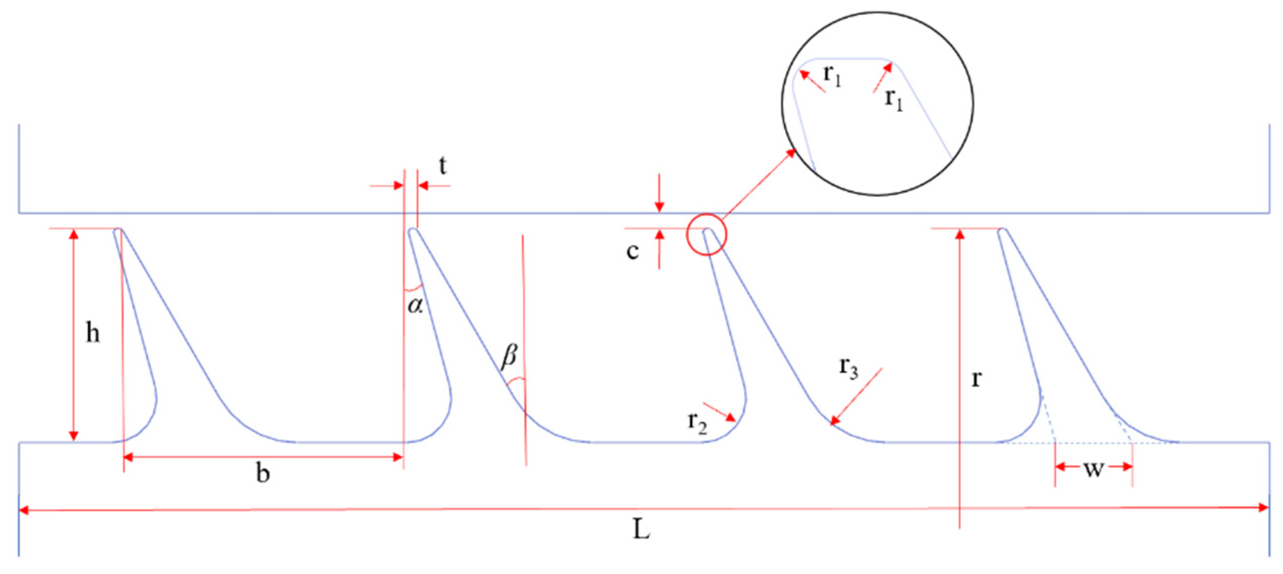
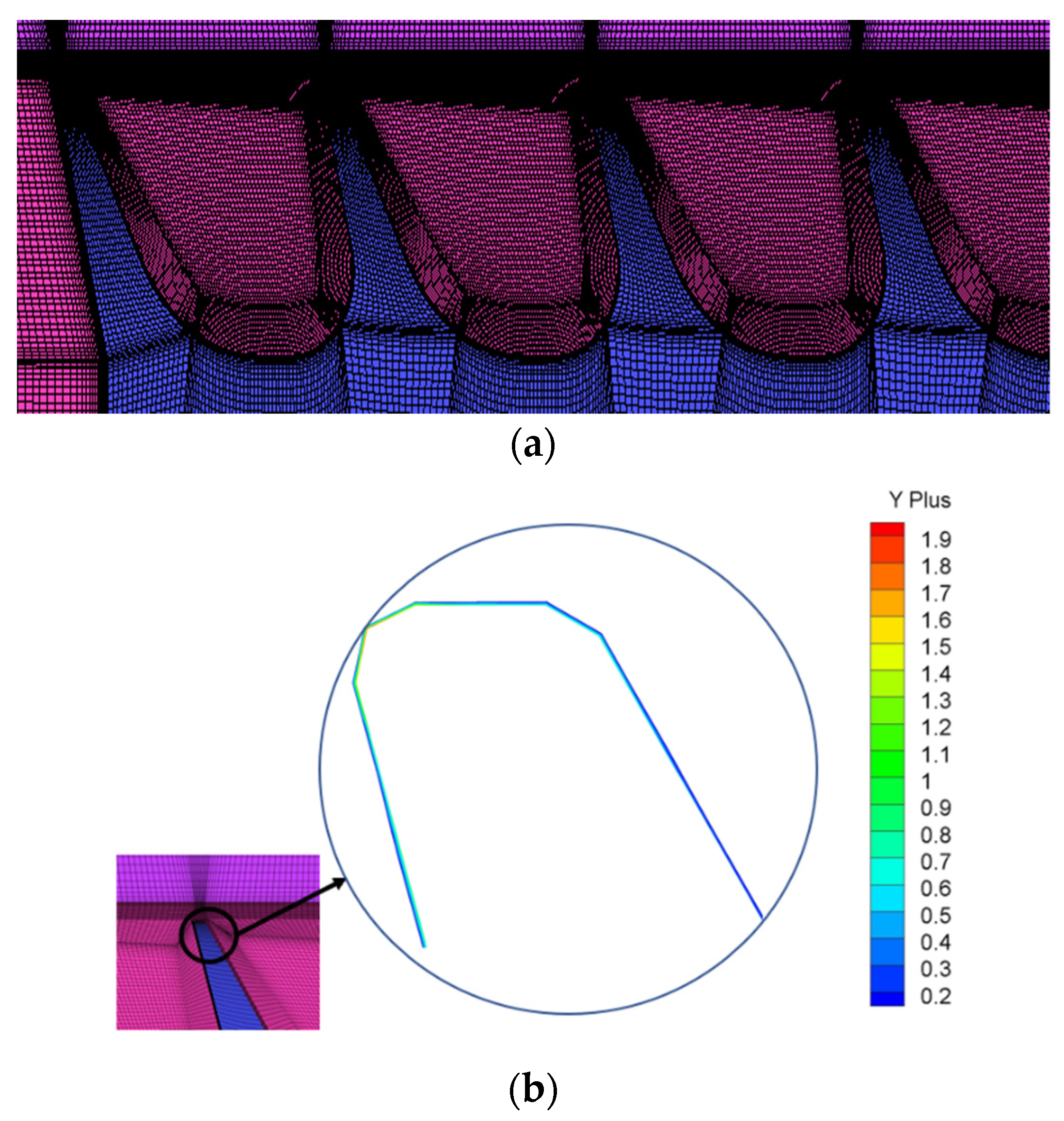
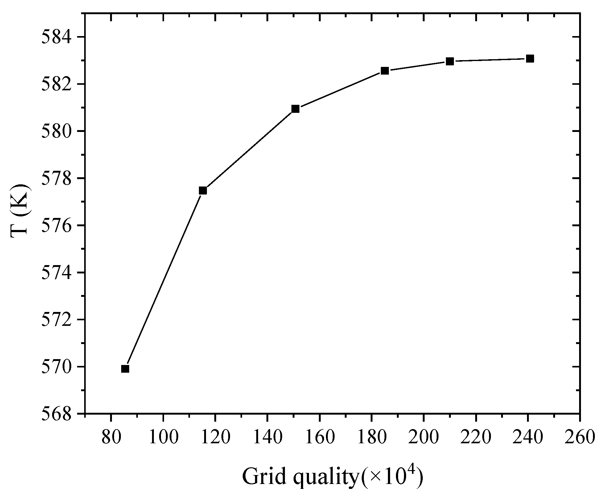
2.1. Model Structure and Meshing

The research object of this paper is the oblique labyrinth seal model, with model rotation radius r = 188.2 mm. The basic geometrical dimensions are as follows: clearance c = 0.35 mm, tooth width t = 0.3 mm, root thickness w = 1.685 mm, fillet radius at tip r1 = 0.05 mm, fillet radius at root r2 = 1 mm, fillet radius at root r3 = 2 mm, tooth number n = 4, the rake angle α is 15°, the rake Angle β is 30°, with the X-axis as the rotation axis, as shown in Figure 1, and the application model is as show in Figure 2.
The structural parameters of the model are shown in Table 1. M1 was selected as the reference model to ensure constant irrelevant parameters and boundary conditions. The influence of the change of a single factor on the leakage characteristics, flow field structure and temperature distribution of the labyrinth seal was studied and analyzed.
Figure 3 shows the division of the grid with the contour of y+ values on the labyrinth teeth; 10 boundary layer grids were set on the labyrinth rotor wall and stator wall, with a total thickness of 0.05 mm. In order to improve the mesh quality and calculation precision of the boundary layer, local mesh encryption was carried out for the part of the tip with dense heat exchange, and for the near-wall area of the cavity with complex flow field changes, so as to better simulate the fluid flow in the cavity.
The mesh-independent verification of the numerical simulation model shows that when the number of meshes exceeds 1.85 million, the effect of increasing the number of meshes on the outlet average temperature is very small. Therefore, the number of grids should be greater than 1.85 million to obtain relatively stable results. In order to save computing resources, 1.85 million grids were selected for numerical calculation as is shown in Figure 4.

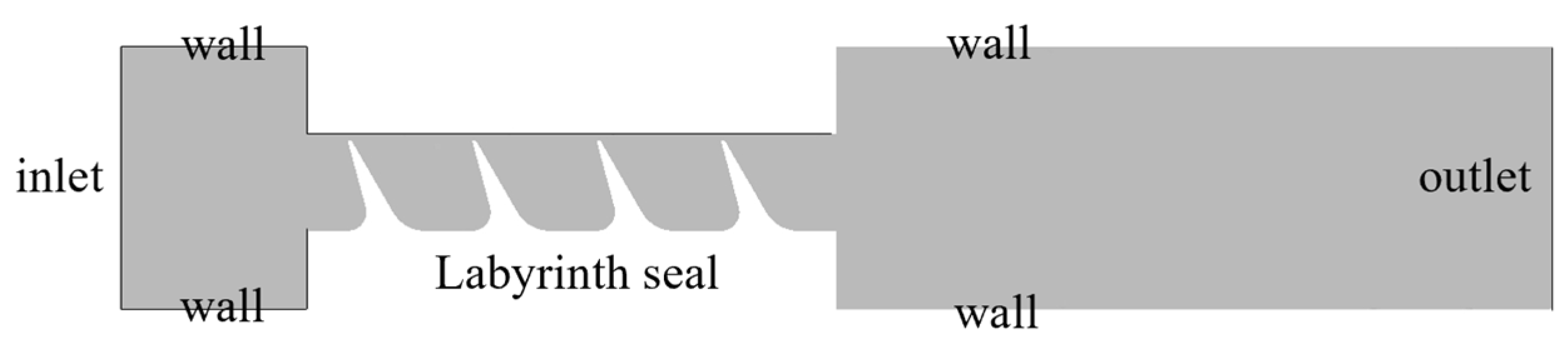
2.2. Boundary Conditions and Parameter Definitions

A three-dimensional model of the labyrinth seal was established by taking the radial section of the labyrinth seal and rotating it by 0.5°. The radial section was a periodic boundary. Fluent was used to solve the three-dimensional steady-state model, and the Standard K-Omega turbulence model equation and SIMPLE algorithm were used to calculate the coupling of pressure and velocity. The inlet and outlet boundary are pressure inlet and pressure outlet, and the working pressure ratio was 1.2. The computational domain and boundaries are shown in Figure 5.
When the heat transfer characteristics of the labyrinth seal structure were studied, the wall temperature T of the outer surface of the labyrinth seal rotor and the outer surface of the labyrinth seal stator were both 300 K at the beginning. The working medium was air, which is an ideal gas. The specific heat at constant pressure is 1006.43, the thermal conductivity is 0.0242 W / m · K , and the isentropic adiabatic coefficient of air at 600 K is 1.376. The Sutherland formula [21] was used to calculate the variation of air viscosity with temperature. The rotor part and stator part were made of steel, the detailed parameters of the steel are as follows: the density of the steel was 8030 kg/s, the specific heat of the steel was 502.48 J / kg · K , and the thermal conductivity of the steel was 16.27 W / m · K .
The discharge coefficient Cd is introduced as the parameter to evaluate the sealing performance, and its definition is,
C d = m ˙ r m ˙ i
where m ˙ r is the flow measured by the flowmeter in the experiment, m ˙ i is the ideal flow,
m ˙ i = p 0 A k R T 2 k 2 k 1 ( p n p 0 ) 2 k [ 1 ( p n p 0 ) k + 1 k ]
where p 0 and p n are the total pressure at the sealing inlet and the static pressure at the outlet, A is the cross-sectional area of the sealing clearance, k is the air adiabatic index, and R is the air gas constant.
The Nusselt number is used to measure the heat transfer characteristics of seals, it is defined as follows,
N u = h l λ
where l is characteristic length, defined as l = 2 c in this paper, and λ is thermal conductivity coefficient. h represents convective heat transfer coefficient, and its definition is,
h = q T w T f
where q means heat flux, T w is the surface temperature of solid, and T f is the fluid temperature near the solid surface.
The continuity equation, the momentum conservation equation and the energy conservation equation are the basic equations for studying the heat transfer characteristics of fluid flow, and their Reynolds time average expressions are as follows.
Conservation of mass (the continuity equation),
ρ U i x i = 0 i = 1 , 2 , 3
Conservation of momentum,
ρ U i U j x j = P x i + x j μ U i x j + U j x i 2 3 μ U l x l δ i j ρ u i u j ¯ i , j = 1 , 2 , 3
Conservation of momentum,
c p ρ T t + ρ U j T x j = x j λ T x j c p ρ u j τ ¯ q R j = 1 , 2 , 3

3. Effect of Geometric Parameters of the Labyrinth Seal on Leakage Characteristics at Different Rotational Speeds

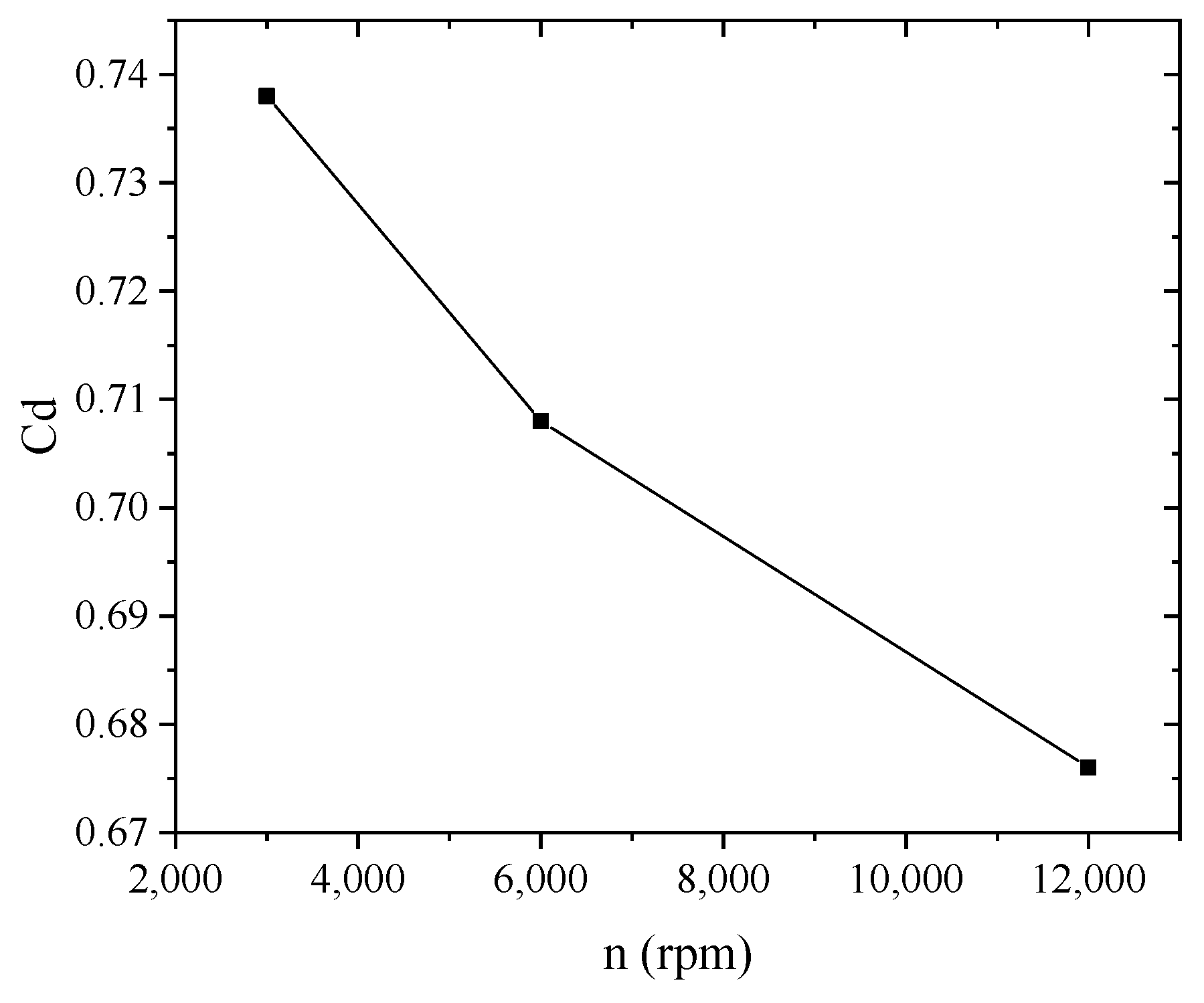
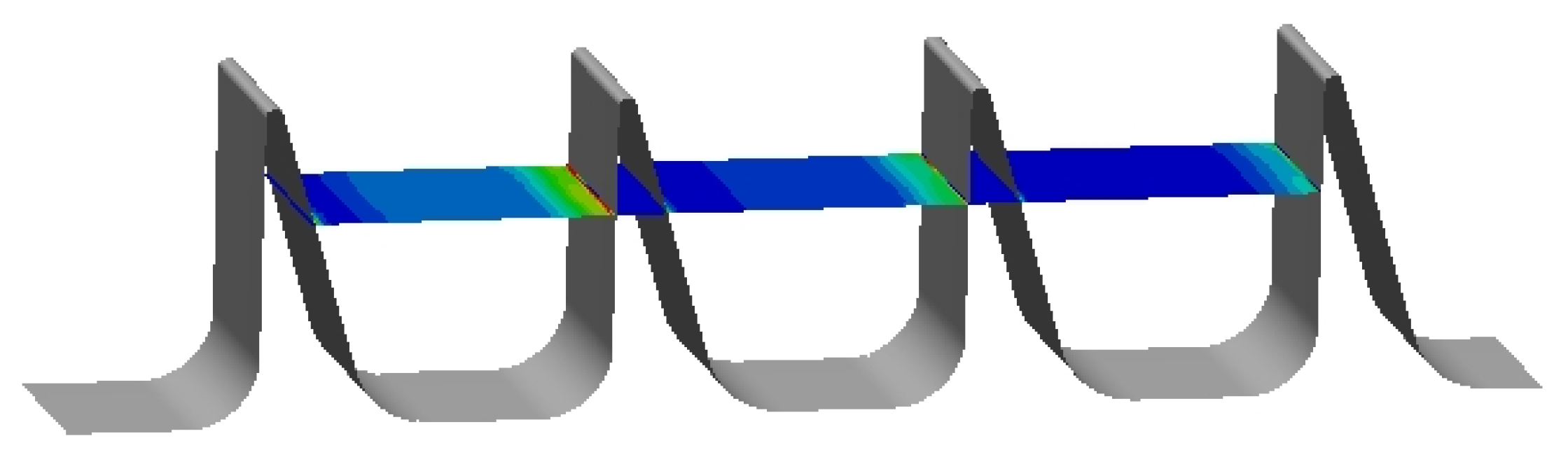
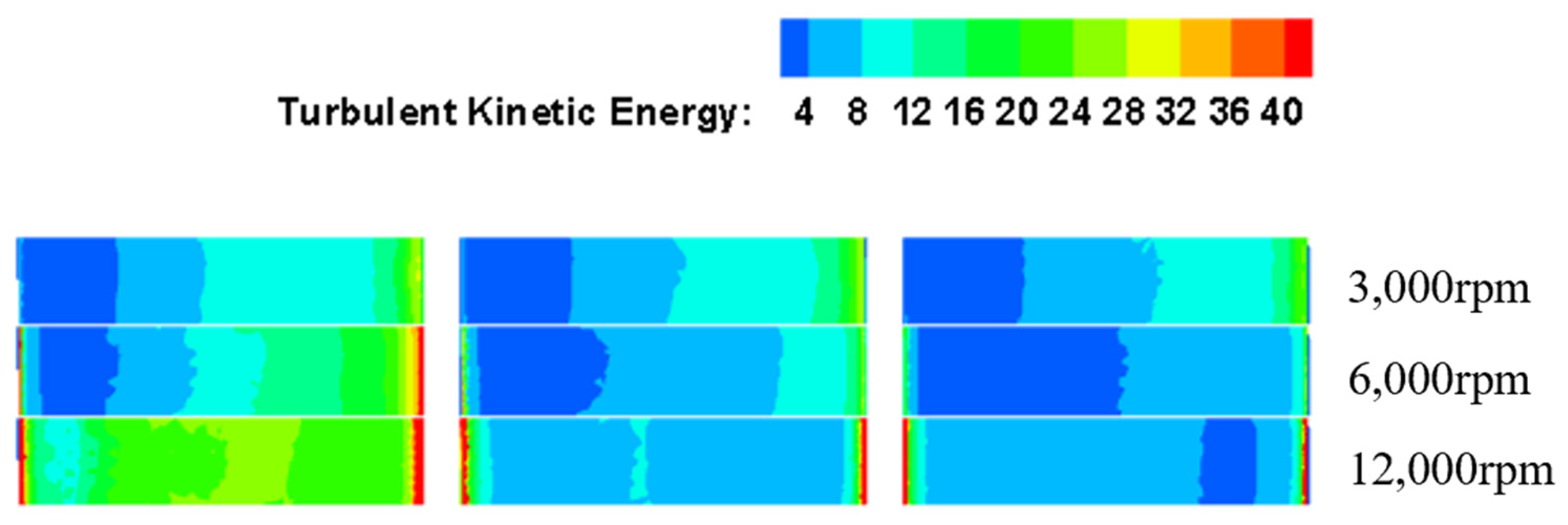
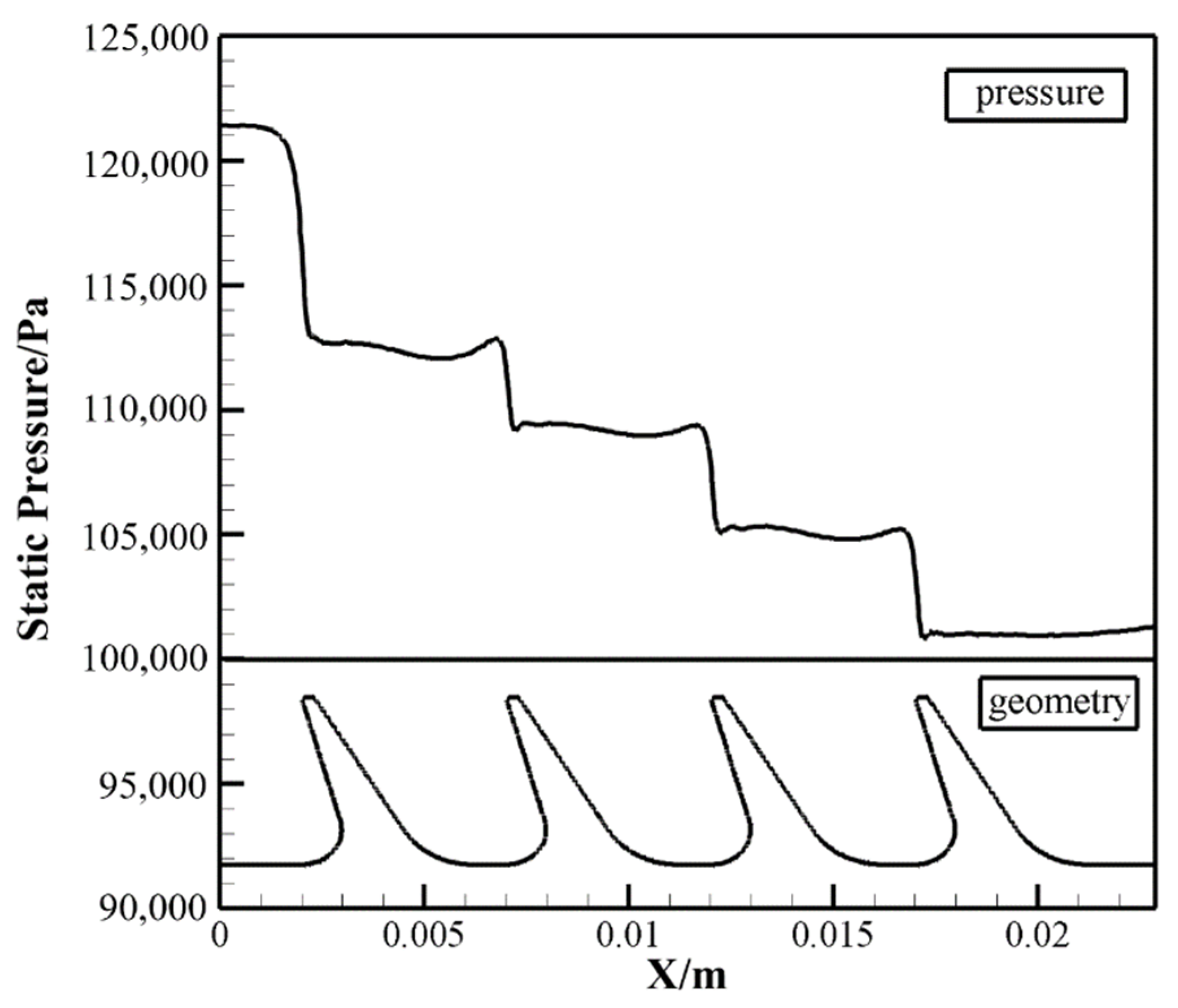
3.1. Effect of Rotational Speed on Labyrinth Seal Flow

Based on model M1, the influence of speed on the flow and heat transfer characteristics of labyrinth seals was studied without considering the radial elongation of tooth depth caused by the increase in speed. Figure 6 is the function diagram of the flow coefficient changing with the speed when the inlet/outlet pressure ratio is 1.2. It can be clearly concluded that the flow coefficient Cd decreases with the increase of the speed.
In order to explore the internal mechanism of the decrease in labyrinth seal leakage caused by the increase of speed, the streamline diagrams at different speeds were compared and analyzed, as shown in Figure 7. The vortex system in the labyrinth cavity is mainly composed of three parts: the back vortex located at the top of the tooth on the leeward side, the cavity vortex located at the center of the labyrinth cavity and the corner vortex located at the root of the labyrinth seal on the windward side. The cavity vortices collide with the bottom of the back vortices after one rotation, and the fluid is forced to bypass the back vortices and flow upward, thus forming local circumferential flow. There exists a large back vortex under low rotational speed. The fluid over the back vortex has a long distance, and the kinetic energy is reduced, so it cannot form an effective impact on the fluid flowing out of the tooth clearance. It even forms a local backflow at the top of the back vortex due to the disturbance of the clearance outflow. When the rotating speed increases, the speed of the tooth cavity vortex increases, the back vortex is compressed, and the circumnavigation distance decreases. Especially when the speed increases to 12,000 rpm, the back vortices are squeezed out and disappear. After a rotation of the cavity vortex, part of the fluid directly impacts on the outlet position of the clearance, thus producing an effective buffer for the axial outlet fluid and reducing its axial velocity. Figure 8 shows the comparison diagram of axial velocity vector of the outflow fluid from the tip clearance at different rotating speeds. The background is the axial velocity cloud diagram. With the increase of rotational speed, the mean axial velocity decreases gradually. In the range of low-pressure ratio and low Mach number (Ma less than 0.3) studied in this paper, the fluid is regarded as incompressible, and the size of the clearance remains unchanged, so the only factor affecting the flow rate is the axial velocity. The above analysis shows that when the rotating speed increases, the impact effect of the outflow fluid in the first stage tooth clearance increases, and the axial velocity decreases, thus the flow coefficient decreases.

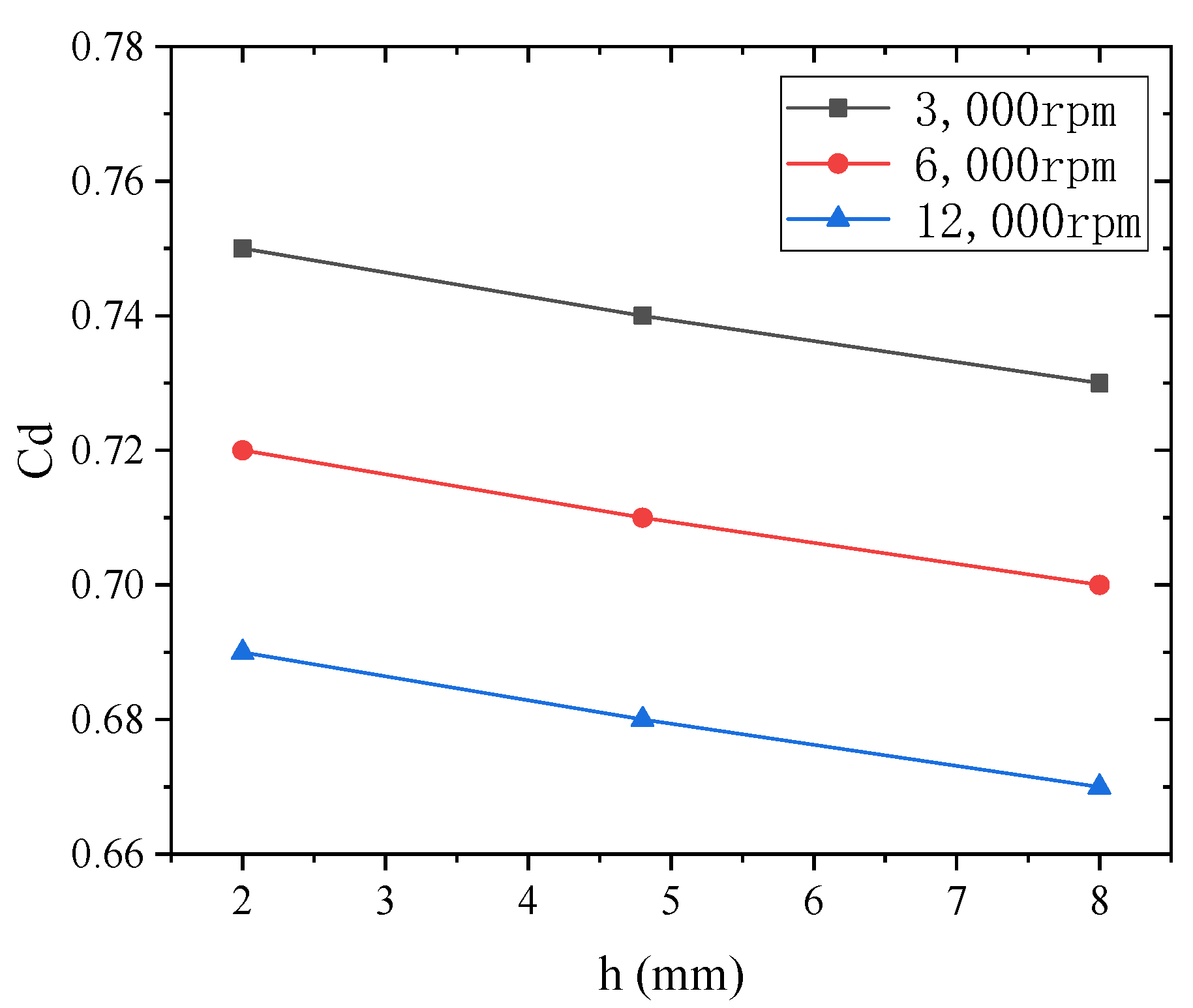
3.2. Effect of Varying Tooth Height on Labyrinth Seal Leakage Characteristics at Different Rotational Speeds

The leakage characteristics of labyrinth seals with different tooth heights under the condition of variable rotation speed were compared and analyzed. The results are shown in Figure 9. There is a negative linear correlation between the labyrinth flow coefficient and the tooth height. The leakage coefficient of labyrinth seals showed a parallel downward trend with the increase of tooth height at different rotation speeds, indicating that this downward trend was independent of the rotation speed.

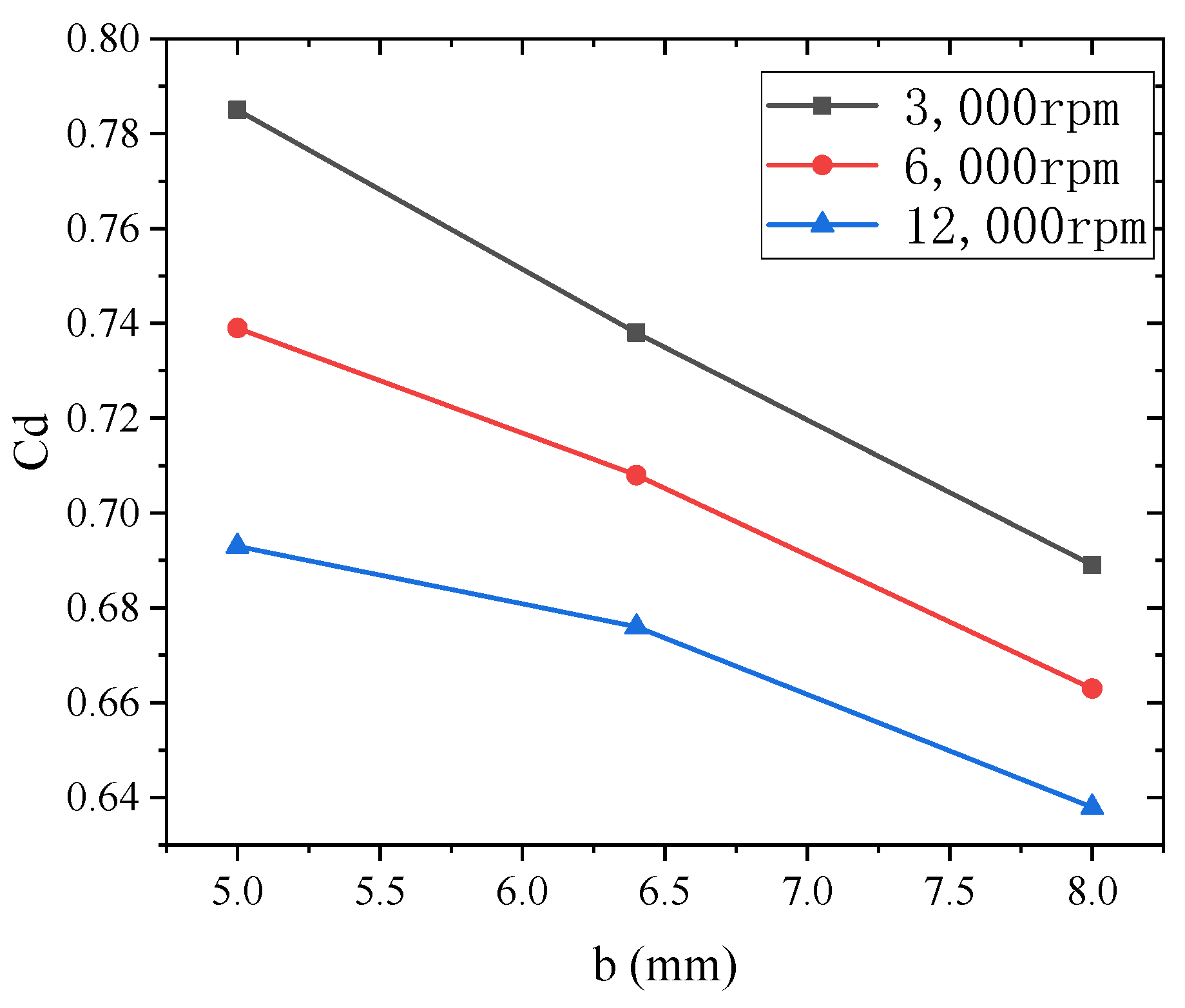
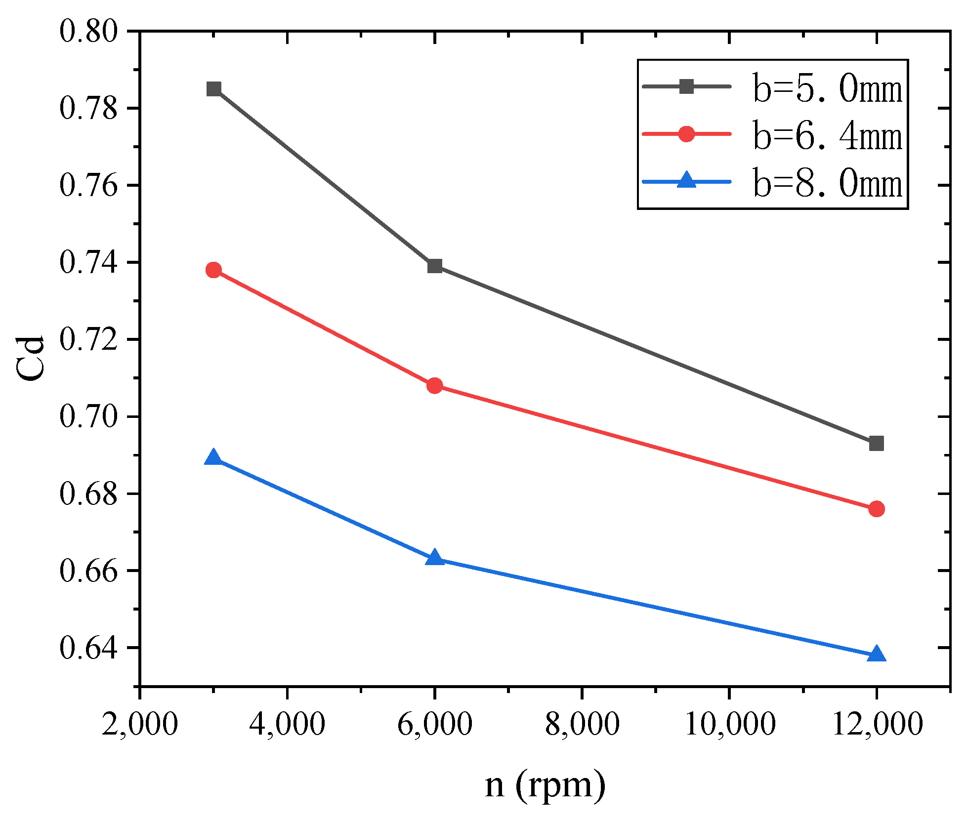
3.3. Effect of Pitch Variation on Labyrinth Seal Leakage Characteristics at Different Rotating Speeds

The flow law of labyrinth seals under the coupling action of different speeds and tooth pitches was studied by simulation. Figure 10 shows the labyrinth seal leakage characteristic curve with the change of tooth pitch at different rotating speeds. Similar to the influence rule of tooth height, the labyrinth seal leakage coefficient decreases with the increase of tooth spacing. However, the downward trend is different at different rotating speeds. It can be seen from the comparison that the decreasing trend of leakage coefficient decreases gradually with the increase of rotational speed.
Looking at this phenomenon from another perspective, Figure 11 shows the leakage characteristic of labyrinth seal curve when the rotating speed changes at different tooth pitch. It was found that the flow coefficient decreases at a greater rate with the increase of rotational speed at a small tooth pitch. The results show that the high rotation speed can improve the sealing performance of labyrinth seals with small pitch.
This is because with a small tooth pitch, the tooth cavity is small, and the disturbance of the fluid in the cavity caused by wall rotation is more easily transmitted to the interior. In other words, compared with large tooth pitch, rotation contributes more significantly to the mixing of vortex in tooth cavity with small pitch. In order to confirm the above viewpoint, the cross section in the tooth cavity at y = 167 mm was intercepted along the flow direction. The contour intercepts the isosurface located in the grate tooth cavity, as shown in Figure 12.
The turbulent kinetic energy cloud images, as shown in Figure 13 and Figure 14, were obtained. It was found that the turbulent kinetic energy is transferred from the near-wall region to the cavity with the increase of rotational speed. The transmission efficiency of small pitch is obviously better than that of large pitch. As a result, the turbulent kinetic energy in the cavity with small pitch is generally higher than that in the cavity with large pitch, which leads to the enhancement of fluid mixing in the cavity with small pitch. Therefore, higher speed is beneficial to improve the sealing performance of labyrinth seal with small pitch.

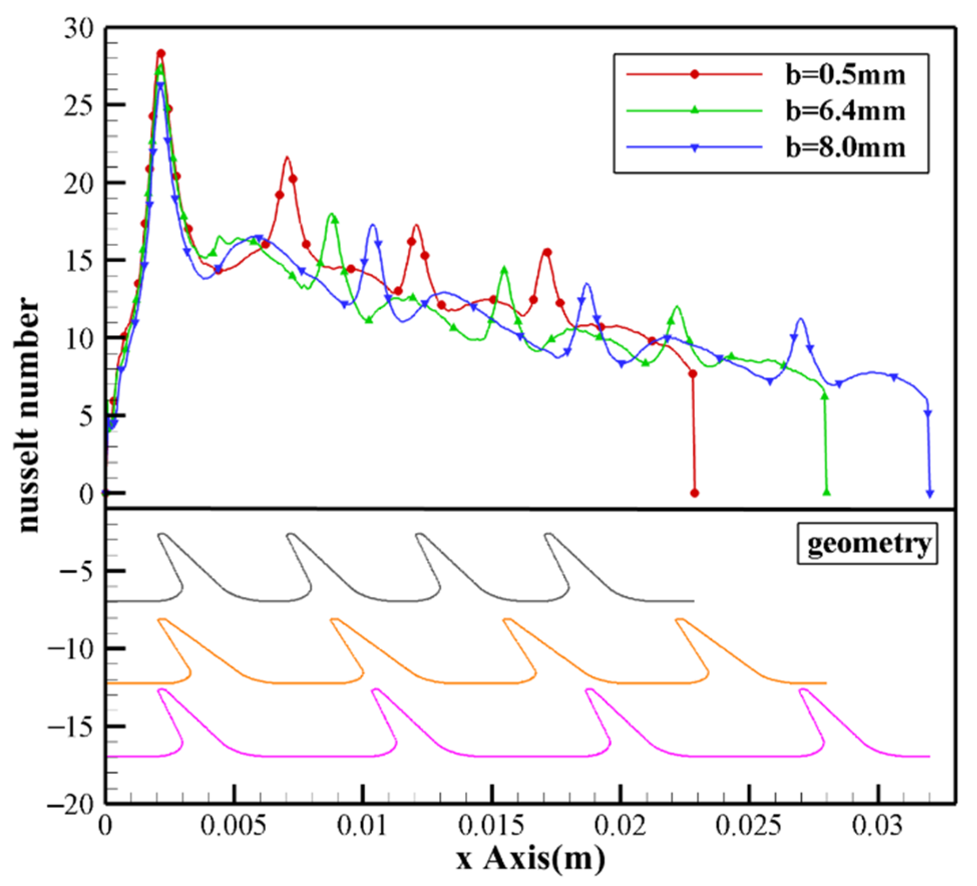
4. Thermodynamic Characteristics of Labyrinth Seal with Varying Tooth Pitch and Rotation Speeds

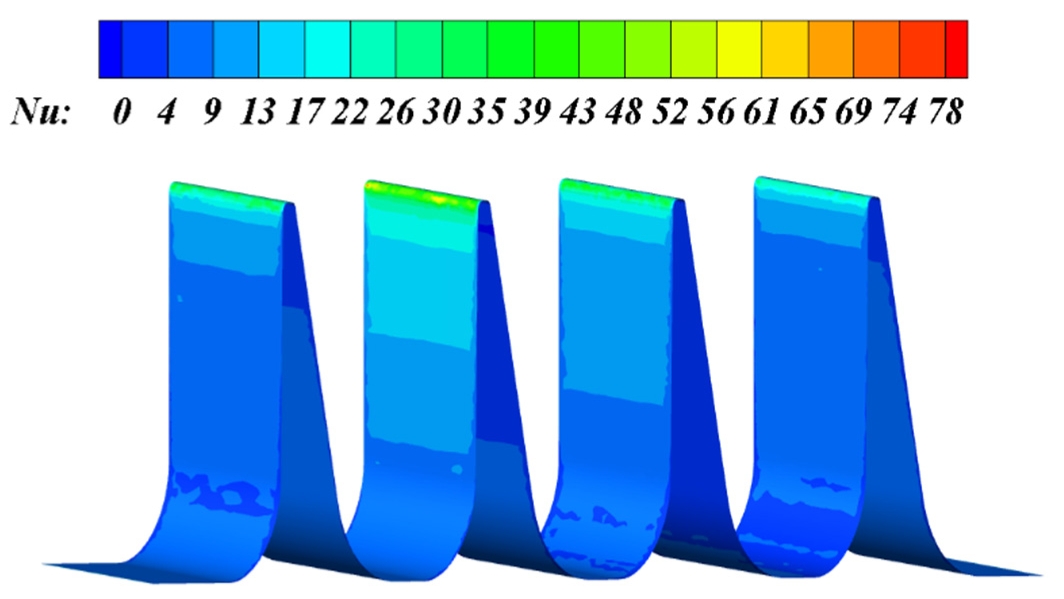
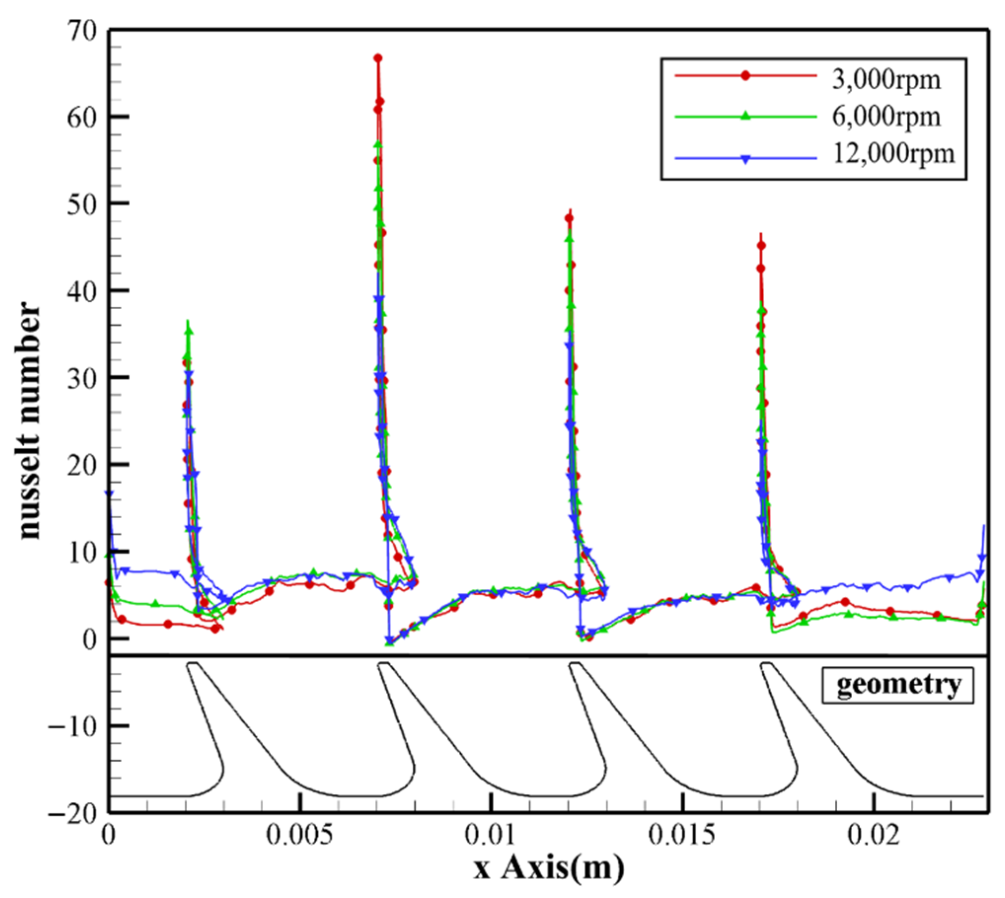
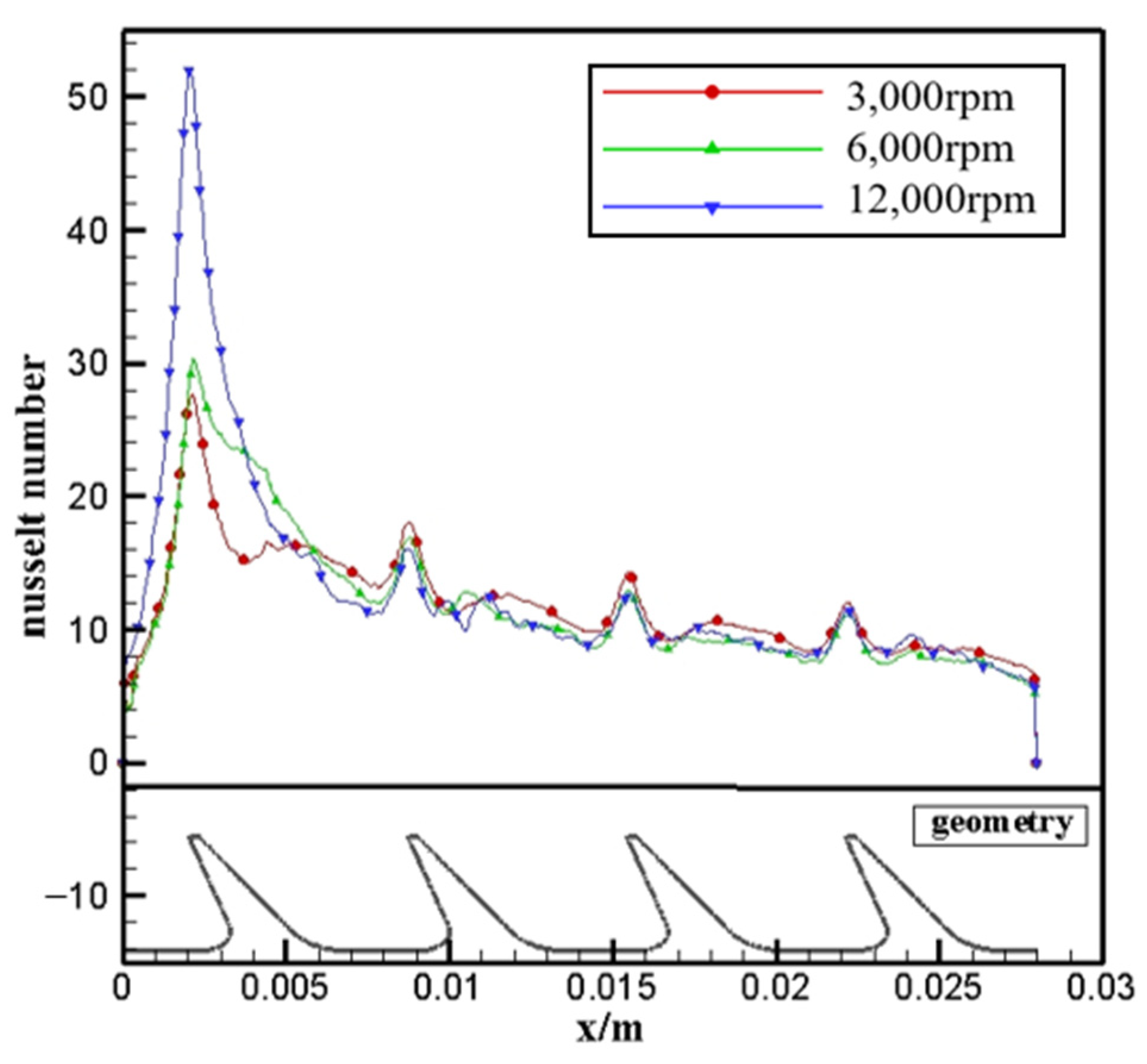
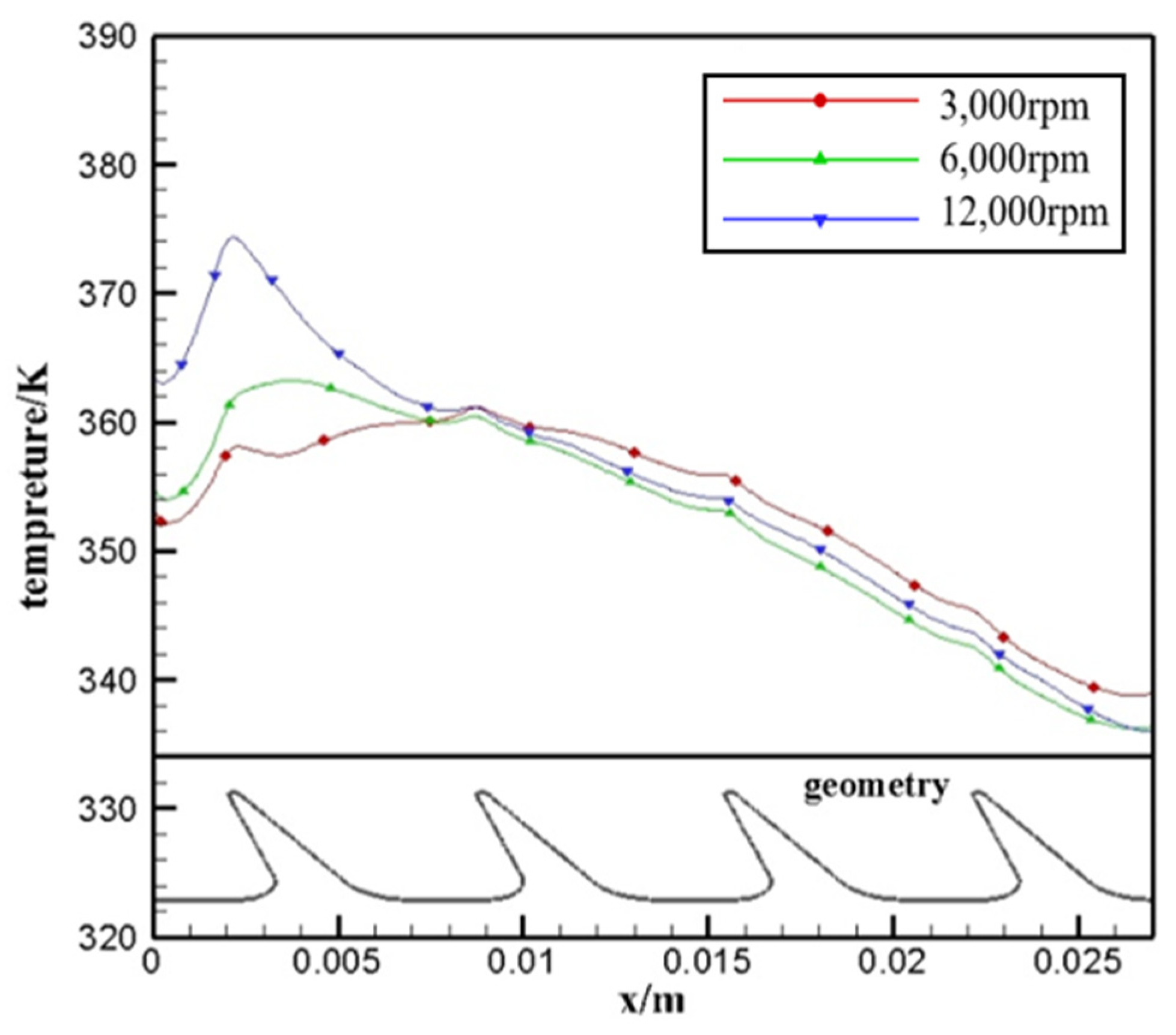
4.1. Analysis of Heat Transfer Characteristics of Rotor Surface

The heat transfer characteristics of the rotor surface were studied and analyzed. The simulation results showed that the stronger convective heat transfer occurs on the windward side of the second labyrinth seal. As shown in Figure 15, the distribution value of the Nusselt number at this position is relatively high. This is because the pressure drop of the fluid is greatest after it has passed through the first throttle gap (Figure 16). The fluid impinges on the windward side of the second labyrinth seal at a higher speed. The mixing effect is strongest in the cavity of the first stage of the labyrinth seal. The temperature gradient of the windward boundary layer is higher, which increases the convective term in convective heat transfer. Compared with the leeward side, it can be seen that the heat transfer intensity near the tooth tip is very low due to fluid separation. The re-attachment of the separation vortices made the heat transfer intensity of the bottom section on the leeward side rise slightly. In addition, with the increase of rotating speed, the temperature rise region gradually increases. The results show that the area of the vortex in the tooth cavity is extended with the increase of rotational speed.
The surface Nusselt number of the labyrinth seal was analyzed at different rotating speeds. Figure 17 shows the distribution of the Nusselt number on tooth surface at different rotating speeds when tooth pitch was 5.0 mm. It was found that the high convective heat transfer occurs on the surface of the tooth tip, and the heat transfer intensity of the other parts is low. With the increase of rotational speed, the peak Nusselt number behind the second tooth decreases. This is because the increase of rotating speed leads to the enhanced mixing effect of vortices in the tooth cavity, which reduces the axial velocity of fluid passing through the second and subsequent labyrinth seals and weakens the heat transfer. At the same time, it was found that the heat transfer intensity of the other cavity walls changes little with the rotation speed. Figure 18 shows that the temperature distribution diagram of the labyrinth seal surface and shows that the influence of rotational speed on the rotor wall temperature is mainly reflected in the first stage of labyrinth seal, where the wall temperature rise is more significant.

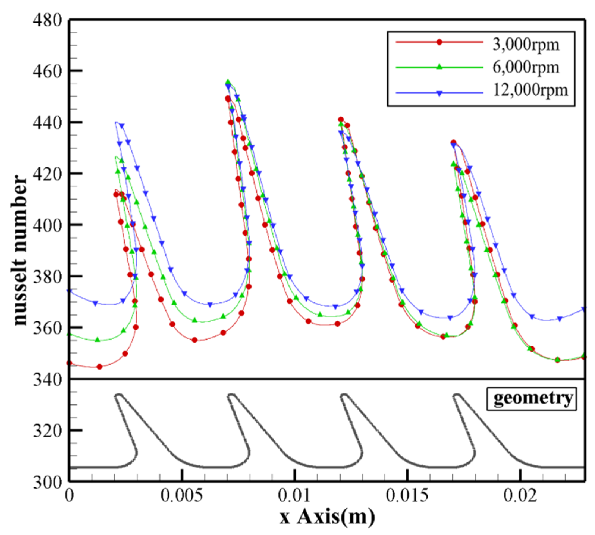
4.2. Analysis of Heat Transfer Characteristics of Stator Surface

First, at the same speed, the position of the centerline of the bushing with different tooth pitch along the process is intercepted to obtain the distribution rule, as shown in Figure 19. It can be seen from the figure that convective heat transfer intensity of labyrinth stator along the flow decreases gradually on the whole, and heat transfer is concentrated in the front segment of labyrinth stator. The extreme value of Nusselt number appears on the downward-facing surface of the bushing near the position of tooth tip. It shows that the convective heat transfer intensity on the rotor surface is higher at the tooth tip position. This is because the velocity of the fluid increases rapidly after passing through the throttle gap, and the hot high-speed fluid impacts the upwind side of the tooth tip and the static bushing. It is found that the extreme Nusselt number on the bushing surface above the tooth tip decreases with the increase of tooth pitch. This finding indicates that the convective heat transfer coefficient is related to the shape and size of the structural components.
The distribution law of Nusselt number along the stator surface at different rotational speeds was studied, and the characteristic curve, as shown in Figure 20, was obtained. The figure still shows that the strong convective heat transfer is concentrated in the front segment of the labyrinth stator surface, and with the increase of the speed, this distribution law becomes particularly significant. It is shown that the convective heat transfer intensity at the position of labyrinth bushing above the tip of the first labyrinth tooth increases sharply, while the Nusselt number at the position of labyrinth bushing above the tip of the subsequent labyrinth teeth decreases. It also indicates that the influence of rotational speed on the heat transfer intensity of labyrinth seals is mainly in the front segment. Figure 21 shows the temperature distribution along the path in the same state. The wall temperature is higher when the heat transfer is strong; otherwise, the wall temperature is lower.

5. Conclusions

In this paper, numerical calculation was carried out for different labyrinth seal models under the condition of variable rotation speeds. The aerodynamic mechanism of the influence of rotating speeds on the leakage characteristics of labyrinth seals was explored, as well as the labyrinth seal leakage characteristics with variable geometric parameters at different rotation speeds and the thermodynamic characteristics of labyrinth seals under the coupling effect of tooth profile parameters and rotational speed. The following conclusions are obtained.
(1) The aerodynamic mechanism of the effect of rotating speed on the leakage characteristics of labyrinth seals is that the kinetic energy of the outflow fluid passed the first clearance is reduced due to the impact of the tooth cavity vortex with the increasing rotating speed. This reduces the flow coefficient and improves the sealing performance of labyrinth seals.
(2) The research on the influence of structural parameters shows that the leakage coefficient of labyrinth seals under the influence of tooth height has a consistent downward trend with the increase of rotational speed. The decreasing trend of labyrinth seal leakage characteristics under the influence of the change of tooth pitch is different with the change of rotation speed. Compared with large pitch, higher rotation speed is more significant to improve the sealing performance of labyrinth seals with small pitch.
(3) Thermodynamic analysis of the rotor shows that the convection heat transfer on the windward side of the second tooth is stronger. This is because the velocity of the airflow increases after passing through the first tooth clearance, so that the heat transfer is significantly strengthened. Therefore, the extreme value of convective heat transfer intensity exists in the area near the tip of tooth. The effect of rotating speed on the wall temperature of the rotor is concentrated on the first tooth.
(4) The thermodynamic analysis of the stator shows that the extreme value of Nusselt number at the tooth tip decreases with the increase of tooth pitch, and the convective heat transfer intensity decreases along the path. The influence of rotating speed on the heat transfer of the bushing surface is shown as follows; with the increasing of rotating speed, the heat transfer intensity of the bushing surface above the tip of the first tooth increases, while the heat transfer intensity of the bushing surface above the tip of the subsequent tooth decreases.

Author Contributions

Conceptualization, Z.W. and B.Z.; methodology, Z.W.; software, Z.W.; validation, Z.W., Y.C. and S.Y.; formal analysis, Y.C.; investigation, H.L.; resources, H.J.; data curation, Z.W.; writing—original draft preparation, Z.W.; writing—review and editing, Z.W.; visualization, Z.W.; supervision, B.Z.; project administration, B.Z. All authors have read and agreed to the published version of the manuscript.

Funding

This research was supported by the National Science and Technology Major Project of China (grant No: 2017-III-0011-0037).

Institutional Review Board Statement

Not applicable.

Informed Consent Statement

Not applicable.

Data Availability Statement

The study did not report any data.

Conflicts of Interest

The authors declare no conflict of interest.

References

  1. Scherer, T.; Waschka, W.; Wittig, S. Numerical predictions of high-speed rotating labyrinth seal performance: Influence of rotation on power dissipation and temperature rise. Int. Symp. Heat Transf. 1992, 26, 1514–1522. [Google Scholar]
  2. Wang, D.J.; Su, Y.L.; Luo, X. Experimental investigation on leakage flow characteristics in rotating labyrinth seals. Gas Turbine Exp. Res. 2007, 2, 41–44. [Google Scholar]
  3. Wang, P.F.; Liu, Y.F.; Guo, W.; Li, J.; Liu, B. Influence of high rotational speeds on the labyrinth sealing characteristics. Gas Turbine Exp. Res. 2007, 2, 45–48. [Google Scholar]
  4. Kong, X.Z.; Liu, G.W.; Lei, Z.; Chang, R.; Liu, Y. Experiment on influence of rotational speeds on labyrinth seal in compressor stator well. J. Aerosp. Power 2016, 31, 1575–1582. [Google Scholar]
  5. Denecke, J.; Dullenkopf, K.; Wittig, S.; Bauer, H.-J. Experimental investigation of the total temperature increase and swirl development in rotating labyrinth seals. In Proceedings of the ASME Turbo Expo 2005: Power for Land, Sea, and Air, Reno, NV, USA, 6–9 June 2005. [Google Scholar]
  6. Kong, X.; Liu, G.; Liu, Y.; Zheng, L. Experimental testing for the influences of rotation and tip clearance on the labyrinth seal in a compressor stator well. Aerosp. Sci. Technol. 2017, 71, 556–567. [Google Scholar] [CrossRef]
  7. Fang, J.; Liu, C.L.; Simos, T.E.; Famelis, I.T. Neural network solution of single-delay differential equations. Mediterr. J. Math. 2020, 17, 30. [Google Scholar] [CrossRef]
  8. Li, T.; Yang, W. Solution to chance constrained programming problem in swap trailer transport organisation based on improved simulated annealing algorithm. Appl. Math. Nonlinear Sci. 2020, 5, 47–53. [Google Scholar] [CrossRef]
  9. Waschka, W.; Wittig, S.; Kim, S. Influence of high rotational speeds on the heat transfer and discharge coefficients in labyrinth seals. J. Turbomach. 1992, 114, 462–468. [Google Scholar] [CrossRef]
  10. Micio, M.; Facchini, B.; Innocenti, L.; Simonetti, F. Experiment investigation on leakage loss and heat transfer in a straight through labyrinth seal. In Proceedings of the ASME 2011 Turbo Expo: Turbine Technical Conference and Exposition, Vancouver, BC, Canada, 6–10 June 2011. [Google Scholar]
  11. Willenborg, K.; Kim, S.; Wittig, S. Effects of reynolds number and pressure ratio on leakage loss and heat transfer in a stepped labyrinth seal. J. Turbomach. 2001, 123, 815–822. [Google Scholar] [CrossRef]
  12. Liu, G.W.; Chen, K.; Gang, T.; Zheng, H.L. Influences of pressure ratio and Reynolds number on flow characteristics of labyrinth seal in compressor stator well. J. Aerosp. Power 2015, 30, 1554–1560. [Google Scholar]
  13. Alizadeh, M.; Nikkhahi, B.; Farahani, A.S.; Fathi, A. Numerical study on the effect of geometrical parameters on the labyrinth-honeycomb seal performance. Proc. Inst. Mech. Eng. Part G J. Aerosp. Eng. 2018, 232, 362–373. [Google Scholar] [CrossRef]
  14. Simos, T.E.; Tsitouras, C. Explicit, ninth order, two step methods for solving inhomogeneous linear problems x″(T) = Lambda X(T) Plus F(T). Appl. Numer. Math. 2020, 153, 334–351. [Google Scholar] [CrossRef]
  15. Abozaid, A.A.; Selim, H.H.; Gadallah, K.A.; Hassan, I.A.; Abouelmagd, E.I. Periodic orbit in the frame work of restricted three bodies under the asteroids belt effect. Appl. Math. Nonlinear Sci. 2020, 5, 157–176. [Google Scholar] [CrossRef]
  16. Du, X.; Tian, W.; Pan, J.; Hui, B.; Sun, J.; Zhang, K.; Xia, Y. Piezo-phototronic effect promoted carrier separation in coaxial p-n junctions for self-powered photodetector. Nano Energy 2022, 92, 106694. [Google Scholar] [CrossRef]
  17. Zhang, B.; Dou, Y.; Hong, Q.; Ji, H. Experimental investigation of effect of tooth geometrical parameters to flow characteristics in slant labyrinth seals. Concurr. Comput. Pract. Exp. 2018, 30, e4951. [Google Scholar] [CrossRef]
  18. Liu, G.; Jiang, Z.; Wu, W.; Xia, Q.Z. Investigation on effects of rectangular groove on leakage of straight-trough labyrinth seal based on numerical simulation. J. Propuls. Technol. 2013, 34, 181–186. [Google Scholar]
  19. Zhang, B.; Li, J.; Li, W.; Ji, H. Influence of geometric Tooth Shape parameters of labyrinth seals on the Flow Law and the Algorithm. Russ. Phys. J. 2021, 64, 1122–1129. [Google Scholar] [CrossRef]
  20. Du, F.Q.; Ji, H.H.; Shuai, H.S.; Zhang, B.; Wang, D.; Lu, H.Y.; Deng, M.C. Orthogonal experiment of effect of fin geometrical parameters on leakage of straight-through labyrinth seals. J. Aerosp. Power 2013, 28, 825–831. [Google Scholar]
  21. Adam, B. Sutherland formula for a square-well fluid. Phys. Rev. E Stat. Nonlinear Soft Matter Phys. 2006, 73, 011203. [Google Scholar]
Figure 1. Geometric parameter model of labyrinth seal.
Coatings 12 00586 g001
Figure 2. The application model.
Coatings 12 00586 g002
Figure 3. The grid of labyrinth seals. (a) The entire grid of labyrinth seals; (b) encrypted partial grid and contour of y+ values.
Coatings 12 00586 g003
Figure 4. Variation curve of outlet average temperature with different number of grids.
Coatings 12 00586 g004
Figure 5. The computational domain and boundaries.
Coatings 12 00586 g005
Figure 6. Relation between flow coefficient and speed.
Coatings 12 00586 g006
Figure 7. Labyrinth cavity eddies at various rotation velocities.
Coatings 12 00586 g007
Figure 8. Comparison of axial velocities in the fluid domain of labyrinth clearance.
Coatings 12 00586 g008
Figure 9. Tooth height–leakage characteristic curve at different rotating speeds.
Coatings 12 00586 g009
Figure 10. Tooth pitch–leakage characteristic curve at different rotating speeds.
Coatings 12 00586 g010
Figure 11. Rotating speed–leakage characteristics curve at different pitch.
Coatings 12 00586 g011
Figure 12. The isosurface where the contour is located.
Coatings 12 00586 g012
Figure 13. Turbulent kinetic energy cloud diagram of cross section in tooth cavity with 5 mm pitch at different rotating speeds.
Coatings 12 00586 g013
Figure 14. Turbulent kinetic energy cloud diagram of cross section in tooth cavity with 8 mm pitch at different rotating speeds.
Coatings 12 00586 g014
Figure 15. Nusselt number distribution on labyrinth seal surface.
Coatings 12 00586 g015
Figure 16. Pressure drop of fluid along the flow path.
Coatings 12 00586 g016
Figure 17. Nusselt number distribution along the tooth surface.
Coatings 12 00586 g017
Figure 18. Temperature distribution on tooth surface.
Coatings 12 00586 g018
Figure 19. Nusselt number distribution of labyrinth bushing with different tooth spacing along the path.
Coatings 12 00586 g019
Figure 20. Nusselt number distribution of labyrinth bushing along the path.
Coatings 12 00586 g020
Figure 21. Temperature distribution of labyrinth bushing along the path.
Coatings 12 00586 g021
Table 1. Labyrinth seal model parameters table.
ModelDepth h/mmPitch b/mm
M14.86.4
M24.85
M34.88
M436.4
M566.4
Publisher’s Note: MDPI stays neutral with regard to jurisdictional claims in published maps and institutional affiliations.

