Article

Influence of Texture and Thickness of Pyrocarbon Coatings as Interphase on the Mechanical Behavior of Specific 2.5D SiC/SiC Composites Reinforced with Hi-Nicalon S Fibers

Université Paris-Saclay, CEA, Service de Recherches Métallurgiques Appliquées, 91191 Gif-Sur-Yvette, France
*
Author to whom correspondence should be addressed.
Deceased.
Coatings 2022, 12(5), 573; https://doi.org/10.3390/coatings12050573
Submission received: 15 March 2022 / Revised: 14 April 2022 / Accepted: 19 April 2022 / Published: 22 April 2022
(This article belongs to the Special Issue Advanced Composites and Coatings for Nuclear Applications)

Abstract

:
In the framework of SiC/SiC composite development for nuclear applications, the influence of pyrocarbon interphase texture and thickness on the mechanical behavior both on as-processed materials and on irradiated materials is a major concern. Thus, the PyC interphase influence has to be clearly addressed to define its optimal chemical vapor infiltration processing parameters. For this purpose, specific 2.5D SiC/SiC composites reinforced with Hi-Nicalon S fibers and with two kinds of PyC texture and thickness were produced. Transmission electronic microscopy allowed PyC thickness and microstructure/texture characterizations, whereas push-out and tensile tests were employed as experimental mechanical procedures. The original result is that PyC nature directly influences the interfacial shear stress and failure mode of the weakest interface, regardless of the PyC thickness within the studied range. Adhesive failure or cohesive failure are highlighted depending on the PyC CVI deposition mechanisms. Similar post-irradiation characterizations will be required to assess the role of irradiation on the PyC microstructure/texture evolution and mechanical behavior of these materials.

1. Introduction

SiC composites are widely studied for high-temperature severe environment applications. They are being introduced in aero-engines or land-based gas turbines in hot section components to replace superalloys to increase the performance while reducing the weight [1,2,3]. SiC excellent behavior in a neutron environment at high temperatures [4,5] is of particular interest for nuclear power plant core applications [6], where SiC/SiC could improve the performance and safety of light water reactors (LWR) [7]. These materials are also one of the best options for the development of generation IV high-temperature nuclear reactor core materials [6].
For these applications, 3rd generation SiC fibers (Hi-Nicalon S, Tyranno SA3 or SA4 and Sylramic) reinforced SiC/SiC composites are considered because of their excellent corrosion resistance. Up to now, Hi-Nicalon S (HNS) fibers seem to be more relevant for nuclear applications [6,8], even if recent studies tend to demonstrate that neutron irradiation leads to fiber degradation at a high dose and/or low irradiation temperature [9,10,11].
In these materials, the deposition of an interphase (small coating) between the fiber and the matrix is required to ensure a specific fiber/matrix bonding. This fiber/matrix bonding must be strong enough to guarantee load transfer from the matrix to the fibers but not too strong to deflect matrix cracks at the interface (through interfacial debonding) [12]. Currently, for nuclear applications, thin pyrocarbon (PyC) deposits are used as an interphase material due to their chemical compatibility with SiC up to high temperatures and their ability to promote interfacial debonding [13,14].
The pyrocarbon interphase microstructure processed by chemical vapor infiltration (CVI) can vary from isotropic to graphitic. Most of these low-temperature CVI pyrocarbons consist of rough laminar (RL) anisotropic pyrocarbon [15]. Many pyrocarbon microstructures with different textural organizations can be produced by changing the CVI parameters. This textural organization is commonly used for PyC classification [15,16]. The influence of the nature of a PyC interphase (thickness and/or texture) on the mechanical behaviors of C/SiC was already studied [17,18,19], but these studies were only dedicated to carbon fiber reinforcement. Although the influence of pyrocarbon interphase thickness is well known in SiC/SiC composites [20,21,22,23,24,25], its textural organization influence has only been studied recently on unidirectional model composites (minicomposites) [26]. Moreover, the irradiation behavior of a carbon phase depends on its microstructure/texture [27], but the consequence on fiber/matrix bonding in SiC/SiC composites is still unknown and needs to be addressed.
In the present work, the influence of both pyrocarbon interphase thickness and texture on mechanical behavior was investigated on HNS reinforced 2.5D SiC/SiC composites. Specific small SiC/SiC specimens were processed for further post-irradiation characterizations. Two pyrocarbon thicknesses and textures were investigated using push-out and mechanical tensile tests to determine the fiber/matrix bonding strength. Pyrocarbon thickness and texture characterizations were assessed by transmission electron microscopy (TEM). Finally, all mechanical characterizations are correlated to PyC microstructure/texture.

2. Materials and Methods

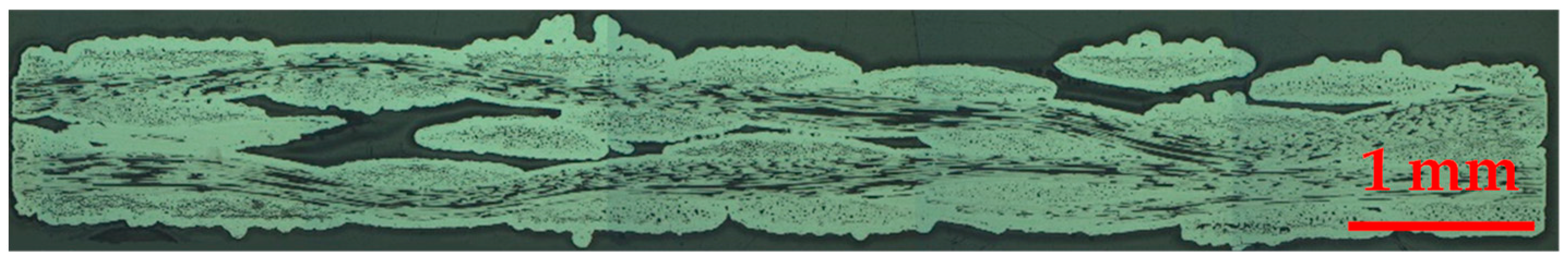
2.1. SiC/SiC Specimen Processing

Hi-Nicalon S (NGS Advanced Fibers Co, Toyama, Japan) fibers were used as reinforcement. The fiber’s properties, provided by the supplier, are summarized in Table 1. Previous studies were dedicated to specific characterizations of this fiber [28,29,30] and concluded that the extreme fiber surface is composed of a thin carbon layer.
The final goal was the production of SiC/SiC specimens compatible with an experimental sodium fast reactor irradiation (BOR-60 in Dimitrovgrad, Russia). To be irradiated, samples need to be small enough to be enclosed in an 80 mm length and 30 mm diameter capsule. In this aim, 2.5D thin woven architecture was produced. This texture improves through-thickness strength, conductivity and delamination resistance in comparison with 2D architecture [31]. The fibrous textile produced is composed of 3 warp and 4 weft layers with 10 yarn/cm density in both directions. PyC interphase and SiC matrix depositions were processed by CVI at a temperature below 1100 °C with propane (C3H8) and methyltrichlorosilane (MTS) + H2 as PyC and SiC precursors, respectively. Two PyC thicknesses and textures samples were produced to evaluate their influence. PyC thicknesses (30 nm and 150 nm) were processed to respect nuclear applications recommendations of SiC/SiC composites ( e P y C   150 nm) [32,33,34]. As previous studies did not highlight a large difference in mechanical behavior within this thickness range, only two different thicknesses were processed. Highly anisotropic (HA) and lowly anisotropic (LA) PyC textures were targeted, as referenced in [26]. After complete CVI SiC matrix densification, plates were cut into small specimens (length = 60 mm and width = 8 mm) for mechanical characterizations. Typical SiC/SiC specimens are presented in Figure 1a; details of specimen orientations for tensile mechanical tests are presented Figure 1b.
As sample roughness is important in comparison with specimen thickness, porosity and section measurements were assessed by image analysis of several optical microscopy sections (Figure 2) rather than by dimensional measurements of samples thickness and width. The resulting characteristics of the manufactured SiC/SiC composites are presented in Table 2 for PyC thicknesses (no effect on PyC texture).

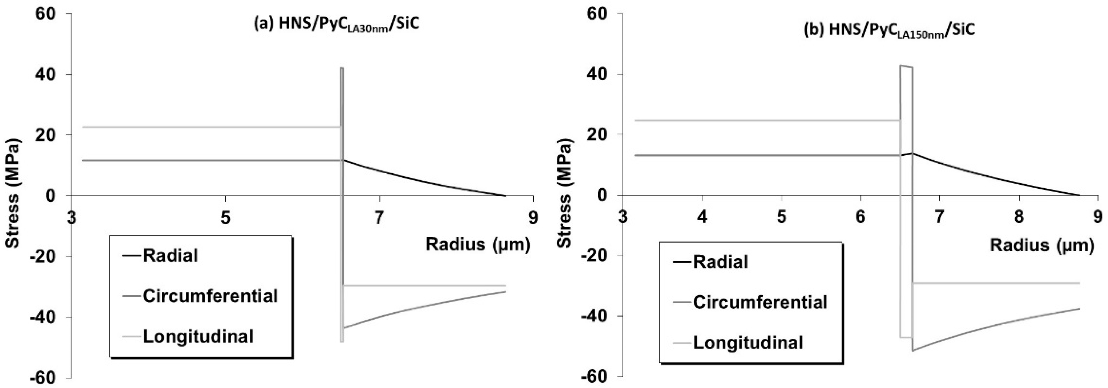
2.2. Thermal Induced Residual Stresses

Thermal residual stresses are generated consecutively to the CVI process final cooling. Detailed thermal-induced residual stresses calculation in each phase (i.e., fiber, interphase and matrix) is detailed elsewhere [35]. Even if the model is based on a single fiber and concentric cylinders of interphase and matrix, good correlations for minicomposites [19] and 2D tubular composites [25,36] have already been reported. The thermomechanical properties as a function of temperature were fitted with Equation (1) and the constants used for the calculations are presented in Table 3.
Y = AT3 + BT2 + CT + D
A, B, C and D are constants, T the temperature (°C) and Y the thermomechanical property.
The calculated residual thermal stresses of all SiC/SiC samples are presented in Figure 3. For all the composites, the level of residual thermal stresses in the fiber and matrix are similar and sufficiently low to ensure that fibers and matrix are undamaged after CVI processing (neither matrix cracks nor fiber failure). No effect of PyC thickness and texture is observed on fiber and matrix residual thermal stresses. The interphase is under tension in radial and circumferential directions and under compression in the longitudinal direction for all SiC/SiC samples. Interphase stresses in longitudinal and circumferential directions are quite high for the HA interphase.

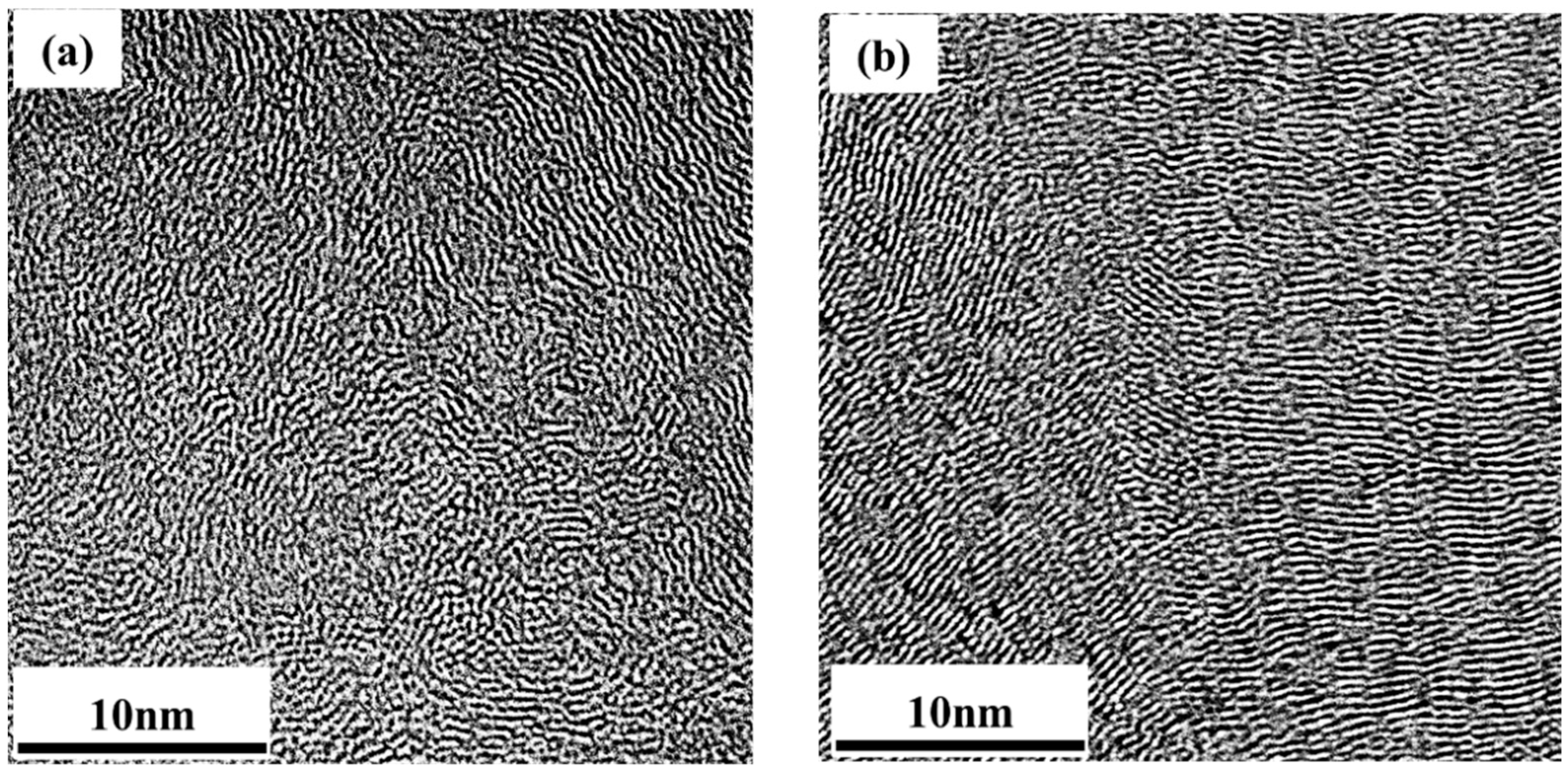
2.3. Characterization of PyC Texture

Due to the low thickness of processed interphases, PyC texture characterization is assessed by transmission electron microscopy (TEM, JEOL, Tokyo, Japan). A JEOL 2011 microscope equipped with a LaB6 gun, operating at 200 kV with a 0.144 nm resolution lattice fringe mode, was used. Sample cross-sections were cut and polished down to 100 μm thickness before final thinning by “ion slicer” apparatus (JEOL). Samples were then deposited on a standard TEM copper grid. The (002) Lattice Fringe (002LF) high-resolution mode was used to obtain the PyC structure and texture. As these pyrocarbon interphases are very thin, it is not possible to employ Raman microspectroscopy (RMS) and/or optical microscopy in the cross-polarization configuration characterizations to use the PyC classification (ReL, RL and SL) used in [15]. That is why only the orientation angle (OA) [15,26,37] was used to distinguish the PyC nature. The higher the OA, the more isotropic the PyC texture is. For OA in the 20–40° range, PyC is highly anisotropic (HA); in the 60–70° range, PyC is lowly anisotropic (LA). Fast Fourier transform (FFT) of 002 lattice fringe was applied on several areas of 30 × 30 nm to determine OA; therefore, this area includes sufficient basic structural units (BSU) for representative OA measurements [26].

2.4. Mechanical Tests

2.4.1. Push-Out Tests

A nano-indentation tester (Nanotest 550, Micro Materials, Wrexham, United Kingdom) was used for single-fiber push-out tests with a maximal load of 500 mN. The same procedure as the one in [26] was employed. The analysis of the load-displacement push-out test curves allows the measurement of the decohesion normal stress (σd) and the interfacial shear stress (τ). σd is the stress needed to break the F/M bond and to initiate the fiber/matrix exfoliation and τ is the stress above which the F/M bonding is completely lost (followed by a free sliding of fiber). σd and τ measurements by push-out tests are the only way to obtain a quantitative evaluation of F/M bonding strength in composites.
To ensure reliable measurements, about 20 fibers were pushed out for each sample. Post mortem SEM observations were conducted to see if the flat punch indenter was centered on the fiber during the push-out test. Otherwise, results were not taken into account.

2.4.2. Tensile Mechanical Tests

Uniaxial tensile tests were performed on an Instron 2404 device (10 kN load cell, Instron, Norwood, United States) using the procedure described in the ISO 20,323 standard [38] on a minimum of 3 samples for each type of material. Samples are glued on end collars on the mechanical testing device with 3M scotch-WeldTM 9323 B/A epoxide structural glue. The crosshead displacement rate was 0.05 mm/min. The strain was measured with a 25 mm gauge length Instron 2620-603 extensometer (±1 mm course) calibrated with a high-resolution numeric calibrator (0.1 μm). Uniaxial tensile tests were performed along the warp direction as described in § 2.1 and Figure 1. An acoustic emission system fixed on the upper-end collar was used for matrix multicracking detection. The measured signal accounts for events over 50 dB (10 dB over background noise) and is presented as a cumulated signal corresponding to events.
To gain information on damage evolution (matrix multicracking) within the composite during tensile mechanical loading, up to 6 unloading–reloading sequences were conducted. Details about this testing procedure are available in [36]. E0 is the initial Young’s modulus (before matrix cracking) and is measured by the slope of the initial linear part of the stress–strain curve. Unloading–reloading cycles lead to the determination of reduced modulus (E/E0), area of the cycles (∆W) and anelastic residual strains after unloading (εr) [39,40]. The longitudinal elastic modulus (E) is determined by measuring the slope of the line passing through the summit of cycle (σmax, emax) and the median point of the cycle for a σmax/2 stress [36,41]. Reduced modulus decreases as a function of applied stress due to matrix multicracking occurring with raising stress. At high stress, if complete matrix multicracking occurs, the reduced modulus reaches an asymptotic behavior related to the fiber fraction in the mechanical solicitation direction and Young’s modulus as expressed in Equation (2). Ef and Vf are the tow Young’s modulus and the fiber volume fraction in composite, respectively. X is the volume fraction of fiber oriented in the tensile mechanical load direction (i.e., warp direction). In this study, X = 0.429 for the specific 2.5D woven architecture described in § 2.1.
lim ε ε max E E 0 = X E f V f E 0

3. Results

3.1. Pyrocarbon Texture Characterization

The pyrocarbon microstructures were observed by HRTEM analysis of the (002) lattice fringes (Figure 4) on 150 nm interphase thickness samples. The OA values measured are presented in Table 4. Results confirmed that there is a strong difference in textural organization between the two kinds of processed pyrocarbon. As expected, LA (OA = 61°) and HA (OA = 44°) textures are confirmed. Even if only OA is not sufficient to thoroughly classify pyrocarbon [15], the detailed analysis of the HRTEM (002) lattice fringes micrograph of the two pyrocarbon tends to demonstrate that PyCLA is probably a smooth laminar (SL) pyrocarbon and PyCHA a rough laminar (RL) pyrocarbon [15]. As RMS and/or polarized optical microscopy analysis of such thin pyrocarbon is not possible to confirm this standard classification of processed pyrocarbon, the LA and HA denomination is retained here.

3.2. Push-Out Tests

At least 20 push-out tests were performed on each type of material to assess the effect of pyrocarbon thickness and texture on the fiber/matrix bonding in HNS/PyC/SiC composites. Figure 5 shows typical push-out test curves for each PyC interphase specimen. The consecutive mean values of σd and τ for all materials are reported in Table 5. σd is three times higher for PyCHA than for PyCLA for a given thickness and decreases when the PyC thickness increases. τ follows the same trends but differences are less pronounced. These results highlight the influence of PyC texture and PyC thickness on F/M bonding in HNS/PyC/SiC composites. PyC thickness reduces the F/M bonding, as previously demonstrated [25,42,43], but to a greater extent for PyCLA interphase than for PyCHA interphase. Finally, the original result is that PyCLA leads to lower F/M bonding strength compared to PyCHA for a similar thickness.

3.3. Tensile Tests

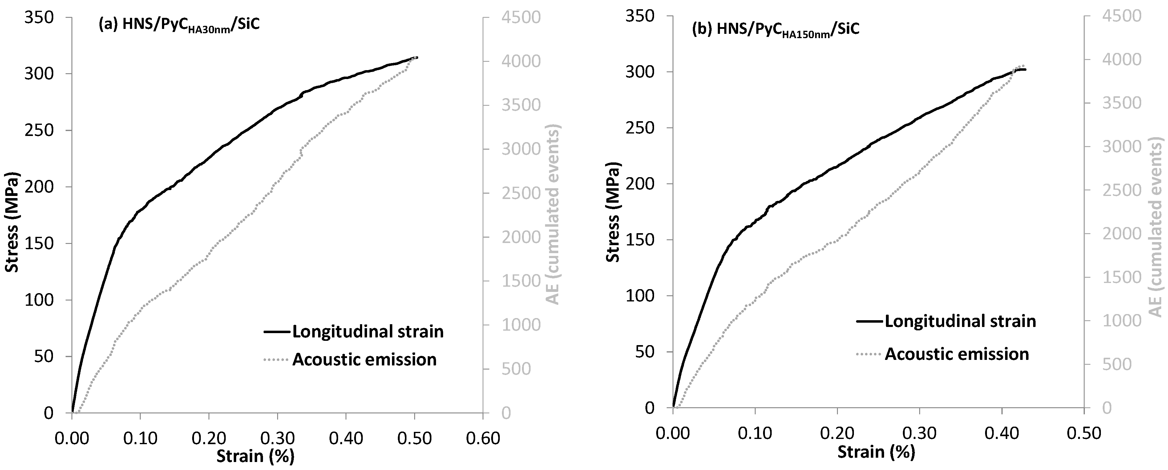
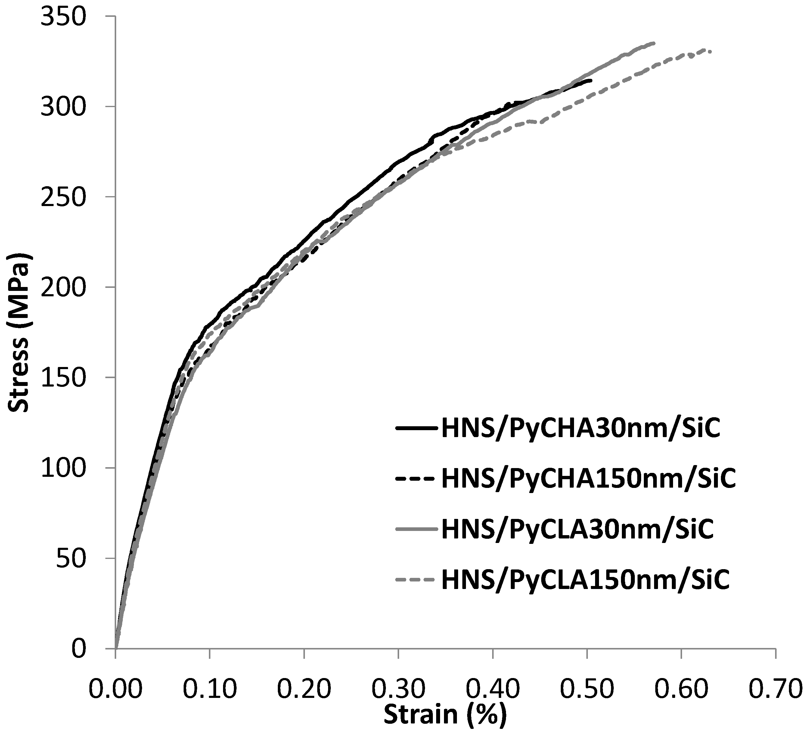
3.3.1. Tensile Mechanical Behavior

Typical stress–strain curves with cumulated AE signals are presented in Figure 6 for each type of SiC/SiC specimen and summarized in Figure 7 for easier comparison. Mechanical properties are given in Table 6. Mechanical behaviors of all specimens are similar and correspond to intermediate/high interfacial shear stress (ISS) mechanical behavior [44,45]. Composites made of PyCLA have lower moduli and higher failure strain than PyCHA composites. No influence of interphase thickness is highlighted. For the same PyC interphase texture (LA or HA), modulus and failure characteristics are similar for 50 and 150 nm PyC thicknesses.
The debonding lengths (fiber pull-out) observed on SEM fracture surface micrographs (Figure 8) tend to confirm push-out results. Debonding lengths seem shorter for PyCHA composites than for PyCLA-based, which could confirm the higher F/M bonding strength for PyCHA interphase. Moreover, the influence of PyC interphase thickness is not clearly visible on PyCHA. This effect seems more visible for PyCLA, with longer debonding lengths for the thickest PyC. At this scale (above the tow scale) and for processed materials, differences between samples are small and only qualitative analysis of fracture surfaces is possible.

3.3.2. Unloading–Reloading Cycles Analysis

Typical stress–strain curves (with unloading–reloading sequences) are presented in Figure 9 for each type of SiC/SiC specimen. The evolution of reduced modulus (E/E0), area of cycles (∆W) and residual strain (εr) as a function of the maximum stress applied before unloading sequences is presented in Figure 10 for all composites.
The evolution of reduced modulus (Figure 10a) is similar for all materials, with a rapid decrease above 50 MPa consecutive to the beginning of the matrix multicracking phenomenon. The saturation value of matrix cracking (Equation (2)) is reached in the 200–250 MPa range, before the ultimate failure, as observed in previous studies on HNS-based composites [25,36]. This tends to demonstrate that ISS is not strong, but intermediate for these materials. No significant influence of interphase texture and/or thickness is observed on reduced modulus. The analyses of the area of cycles (Figure 10b) and residual strains (Figure 10c) evolution led to the same conclusions; therefore, PyC texture and/or thickness (within the studied range) have no significant influence on the composite damage resistance (matrix cracking and/or opening of existing cracks).

4. Discussion

Tensile mechanical behaviors do not clearly put into evidence any effect of PyC texture and thickness. For each PyC texture, PyC thickness (in the 30–150 nm range) has no significant influence on the tensile mechanical behavior, unlike previously observed [20,25,42]. It is possible that the PyC thickness range explored in this study is not sufficient. PyC texture only influences the failure strain, which is higher for a more isotropic PyC texture (PyCLA). Fracture surface analysis (Figure 8) after tensile tests is more interesting to highlight the qualitative effect of PyC texture and thickness. Fiber pull-out is higher for PyCLA than for PyCHA. Moreover, for each kind of texture, thicker PyC interphase leads to longer fiber pull-out. As longer fiber pull-out is related to weaker ISS, it can be deduced that F/M bonding strength is higher for PyCHA and that thicker PyC reduces the ISS.
If mechanical tensile tests and consecutive fracture surfaces only allow assessing the qualitative effect of PyC texture or thickness, push-out tests allow quantitative evaluation of F/M bonding strength by the determination of debonding shear stress (σd) and interfacial shear stress (τ). It is clear that PyCHA induces higher F/M bonding than PyCLA in HNS-reinforced composites, σd being three times higher for PyCHA (Table 5). The influence of PyC thickness is also highlighted for both types of PyC. PyC tends to decrease F/M bonding, as already observed in previous studies [29,30]. It is demonstrated in this study that the influence of PyC thickness is more pronounced for PyCLA. This confirms qualitative observations based on fracture surfaces analysis. To understand the rupture mode of F/M bonding in all materials, high magnification SEM micrographs of typical F/M debonding zone for all specimens after the tensile test are presented in Figure 11.
On all specimens, PyC always remains bonded to the SiC matrix, revealing that the PyC/Matrix (PyC/M) interface is the strongest one, where debonding is never observed. The original result is that PyCLA and PyCHA lead to different failure modes. For PyCLA, interfacial failure occurs between the PyC interphase and the fiber (Figure 11c,d), leading to an adhesive failure as observed in other studies on HNS-reinforced composites [23,46]. The surface of HNS fiber is known to be composed of amorphous carbon resulting from the decomposition of the polymer sizing that is employed to improve weaving and handling capability. Indeed, the amorphous carbon layer/PyC interface is believed to be the weakest region of HNS-reinforced CVI composites, as observed in this case for PyCLA; however, PyCHA leads to a cohesive failure, with part of the PyC interphase remaining on both the matrix and fiber surfaces after fracture (Figure 11a,b), whatever the PyC thickness. This clearly demonstrates that the Fiber/PyCHA (F/PyC) interface is stronger than F/PyCLA one in HNS-reinforced composites. This is the consequence of the stronger adhesion of PyCHA on the fiber surface amorphous carbon. Moreover, PyCHA has the weakest bonds between its basal planes (more graphite-like structure) than PyCLA; therefore, crack deflection between basal planes is more likely to occur in PyCHA. The main difference between PyCHA and PyCLA are CVI processing parameters that pilot the gas phase composition during deposition. As explained in previous studies for RL and SL PyC [16,47], the mechanism of deposition is quite different between PyCHA (i.e., RL PyC) and PyCLA (i.e., SL PyC). On the basis of the contact angle determined in [47], PyCHA leads to an almost 0° contact angle with the substrate. For this type of PyC, a total wetting is believed to occur, leading to a pyrocarbon adhesion energy on the substrate at least equal to its cohesive energy. The contact angle for PyCLA was wider; as a consequence, adhesion energy on the substrate is lower than the cohesive energy within the pyrocarbon. In this previous study, the substrate was pyrographite (HOPG), which is a pure carbon material; similar results can be hinted for the adhesion of PyC on the amorphous carbon on the HNS fiber surface in this study. This analysis tends to confirm experimental results observed by push-out tests and fracture analysis after tensile mechanical tests of processed materials. F/PyC interface bonding is stronger for PyCHA (cohesive failure) than for PyCLA (adhesive failure). This is mainly the consequence of the different deposition mechanisms for both PyCs.

5. Conclusions

The influence of PyC interphase thickness (in the 50–150 nm range) and PyC nature in SiC/SiC composites was studied in detail by tensile mechanical tests and push-out tests. The influence of PyC thickness and PyC nature was minor on tensile behaviors and properties. Only the tensile strain was slightly higher for PyCLA. Fracture surfaces analysis after tensile tests allows a qualitative evaluation of the F/M bonding in composites and brings us to the same conclusion made after the push tests (quantitative measurements of F/M bonding strength). Thicker PyC reduces the F/M bonding strength. This trend is more pronounced for PyCLA than for PyCHA. In all materials, the weakest interface of the PyC interphase domain is the F/PyC interface. PyCHA leads to a cohesive failure with high ISS, whereas PyCLA leads to an adhesive failure with lower ISS. This is the consequence of the CVI deposition mechanisms between these two kinds of pyrocarbon, leading to different adhesion energy.
It has clearly been highlighted that the PyC microstructure/texture is the best processing parameter to control the nature of F/M bonding in SiC/SiC composites reinforced with HNS fibers. This is especially true when a thin PyC interphase is required, such as in nuclear applications, where PyC thickness cannot be significantly modified.
These new results are interesting for the nuclear application of HNS reinforced SiC/SiC composites, for which ISS is known to decrease following irradiation [32,33,48]. The use of PyCHA as an interphase in these composites could be a way to reduce the degradation of F/M bonding following neutron irradiation. The next step will be the characterizations of these composites after a high dose of neutron irradiation to clearly identify the role of PyC interphase nature and thickness on their post-irradiation mechanical behavior. As post-irradiation experiments are quite difficult (experiments need to be conducted in glove boxes or in hot cells), SEM analysis after tensile mechanical tests could be the easiest way to understand the qualitative effect of irradiation on F/M bonding.

Author Contributions

Conceptualization, C.S.; methodology, E.B. and C.S.; validation, C.S. and J.B.; formal analysis, C.S., E.B. and J.B.; investigation, E.B. and C.S.; data curation, C.S. and J.B.; writing—original draft preparation, C.S. and J.B.; writing—review and editing, C.S. and J.B.; supervision, C.S. and J.B.; project administration, C.S. All authors have read and agreed to the published version of the manuscript.

Funding

This research received no external funding.

Institutional Review Board Statement

Not applicable.

Informed Consent Statement

Not applicable.

Data Availability Statement

The data presented in this study are available on request from the corresponding author.

Acknowledgments

The authors acknowledge the support of Jean-Noël Rouzaud for TEM image captures and discussion about pyrocarbon microstructure.

Conflicts of Interest

The authors declare no conflict of interest.

References

  1. Spriet, P. CMC Applications to Gas Turbines. In Ceramic Matrix Composites; John Wiley & Sons, Ltd.: Hoboken, NJ, USA, 2014; pp. 591–608. ISBN 978-1-118-83299-8. [Google Scholar]
  2. DiCarlo, J.A. Advances in SiC/SiC Composites for Aero-Propulsion. In Ceramic Matrix Composites; John Wiley & Sons, Ltd.: Hoboken, NJ, USA, 2014; pp. 217–235. ISBN 978-1-118-83299-8. [Google Scholar]
  3. Lewis, D.A.; Hogan, M.T.; McMahon, J.; Kinney, S. Application of Uncooled Ceramic Matrix Composite for Turbine Blades for Performance Improvement of Advanced Turboshaft Engines; Annual Forum Proceedings-American Helicopter Society: Montréal, QC, Canada, 2008; pp. 961–966. [Google Scholar]
  4. Katoh, Y.; Snead, L.L.; Szlufarska, I.; Weber, W.J. Radiation Effects in SiC for Nuclear Structural Applications. Curr. Opin. Solid State Mater. Sci. 2012, 16, 143–152. [Google Scholar] [CrossRef]
  5. Katoh, Y. Radiation Effects. In Ceramic Matrix Composites; John Wiley & Sons, Ltd.: Hoboken, NJ, USA, 2014; pp. 389–404. ISBN 978-1-118-83299-8. [Google Scholar]
  6. Sauder, C. Nuclear Applications. In Ceramic Matrix Composites; John Wiley & Sons, Ltd.: Hoboken, NJ, USA, 2014; pp. 609–646. ISBN 978-1-118-83299-8. [Google Scholar]
  7. Terrani, K.A. Accident Tolerant Fuel Cladding Development: Promise, Status, and Challenges. J. Nucl. Mater. 2018, 501, 13–30. [Google Scholar] [CrossRef]
  8. Katoh, Y.; Ozawa, K.; Shih, C.; Nozawa, T.; Shinavski, R.J.; Hasegawa, A.; Snead, L.L. Continuous SiC Fiber, CVI SiC Matrix Composites for Nuclear Applications: Properties and Irradiation Effects. J. Nucl. Mater. 2014, 448, 448–476. [Google Scholar] [CrossRef]
  9. Koyanagi, T.; Katoh, Y.; Nozawa, T. Design and Strategy for Next-Generation Silicon Carbide Composites for Nuclear Energy. J. Nucl. Mater. 2020, 540, 152375. [Google Scholar] [CrossRef]
  10. Katoh, Y.; Snead, L.L. Silicon Carbide and Its Composites for Nuclear Applications—Historical Overview. J. Nucl. Mater. 2019, 526, 151849. [Google Scholar] [CrossRef]
  11. Koyanagi, T.; Nozawa, T.; Katoh, Y.; Snead, L.L. Mechanical Property Degradation of High Crystalline SiC Fiber–Reinforced SiC Matrix Composite Neutron Irradiated to ~100 Displacements per Atom. J. Eur. Ceram. Soc. 2018, 38, 1087–1094. [Google Scholar] [CrossRef]
  12. Kagawa, Y. Two Approaches for Interface Design of Continuous Fiber Ceramic Matrix Composites. Ceram. Trans. 1998, 99, 179–185. [Google Scholar]
  13. Lamon, J.; Rebillat, F.; Evans, A.G. Microcomposite Test Procedure for Evaluating the Interface Properties of Ceramic Matrix Composites. J. Am. Ceram. Soc. 1995, 78, 401–405. [Google Scholar] [CrossRef]
  14. Naslain, R. Fibre-Matrix Interphases and Interfaces in Ceramic Matrix Composites Processed by CVI. Compos. Interfaces 1993, 1, 253–286. [Google Scholar] [CrossRef]
  15. Vallerot, J.-M.; Bourrat, X.; Mouchon, A.; Chollon, G. Quantitative Structural and Textural Assessment of Laminar Pyrocarbons through Raman Spectroscopy, Electron Diffraction and Few Other Techniques. Carbon 2006, 44, 1833–1844. [Google Scholar] [CrossRef] [Green Version]
  16. Lavenac, J.; Langlais, F.; Féron, O.; Naslain, R. Microstructure of the Pyrocarbon Matrix in Carbon/Carbon Composites. Compos. Sci. Technol. 2001, 61, 339–345. [Google Scholar] [CrossRef]
  17. Fellah, C.; Braun, J.; Sauder, C.; Sirotti, F.; Berger, M.H. Impact of Ex-PAN Carbon Fibers Thermal Treatment on the Mechanical Behavior of C/SiC Composites and on the Fiber/Matrix Coupling. Carbon Trends 2021, 5, 100107. [Google Scholar] [CrossRef]
  18. Zhao, D.; Guo, T.; Fan, X.; Chen, C.; Ma, Y. Effect of Pyrolytic Carbon Interphase on Mechanical Properties of Mini T800-C/SiC Composites. J. Adv. Ceram. 2021, 10, 219–226. [Google Scholar] [CrossRef]
  19. Duan, H.; Zhang, Z.; Li, L.; Li, W. Effect of Pyrocarbon Interphase Texture and Thickness on Tensile Damage and Fracture in T-700TM Carbon Fiber–Reinforced Silicon Carbide Minicomposites. J. Am. Ceram. Soc. 2022, 105, 2171–2181. [Google Scholar] [CrossRef]
  20. Yang, W.; Araki, H.; Noda, T.; Park, J.Y.; Katoh, Y.; Hinoki, T.; Yu, J.; Kohyama, A. Hi-Nicalon Fiber-Reinforced CVI-SiC Matrix Composites: I Effects of PyC and PyC-SiC Multilayers on the Fracture Behaviors and Flexural Properties. Mater. Trans. 2002, 43, 2568–2573. [Google Scholar] [CrossRef] [Green Version]
  21. Sauder, C.; Brusson, A.; Lamon, J. Influence of Interface Characteristics on the Mechanical Properties of Hi-Nicalon Type-S or Tyranno-SA3 Fiber-Reinforced SiC/SiC Minicomposites: Influence of Interface Characteristics on the Mechanical Properties. Int. J. Appl. Ceram. Technol. 2010, 7, 291–303. [Google Scholar] [CrossRef]
  22. Kabel, J.; Yang, Y.; Balooch, M.; Howard, C.; Koyanagi, T.; Terrani, K.A.; Katoh, Y.; Hosemann, P. Micro-Mechanical Evaluation of SiC-SiC Composite Interphase Properties and Debond Mechanisms. Compos. Part B Eng. 2017, 131, 173–183. [Google Scholar] [CrossRef]
  23. Karakoc, O.; Koyanagi, T.; Nozawa, T.; Katoh, Y. Fiber/Matrix Debonding Evaluation of SiCf/SiC Composites Using Micropillar Compression Technique. Compos. Part B Eng. 2021, 224, 109189. [Google Scholar] [CrossRef]
  24. Nakazato, N.; Kishimoto, H.; Park, J.-S. Appropriate Thickness of Pyrolytic Carbon Coating on SiC Fiber Reinforcement to Secure Reasonable Quasi-Ductility on NITE SiC/SiC Composites. Ceram. Int. 2018, 44, 19307–19313. [Google Scholar] [CrossRef]
  25. Braun, J.; Sauder, C. Mechanical Behavior of SiC/SiC Composites Reinforced with New Tyranno SA4 Fibers: Effect of Interphase Thickness and Comparison with Tyranno SA3 and Hi-Nicalon S Reinforced Composites. J. Nucl. Mater. 2022, 558, 153367. [Google Scholar] [CrossRef]
  26. Buet, E.; Sauder, C.; Sornin, D.; Poissonnet, S.; Rouzaud, J.-N.; Vix-Guterl, C. Influence of Surface Fibre Properties and Textural Organization of a Pyrocarbon Interphase on the Interfacial Shear Stress of SiC/SiC Minicomposites Reinforced with Hi-Nicalon S and Tyranno SA3 Fibres. J. Eur. Ceram. Soc. 2014, 34, 179–188. [Google Scholar] [CrossRef]
  27. Snead, L.L.; Burchell, T.D.; Katoh, Y. Swelling of Nuclear Graphite and High Quality Carbon Fiber Composite under Very High Irradiation Temperature. J. Nucl. Mater. 2008, 381, 55–61. [Google Scholar] [CrossRef]
  28. Dong, S.M.; Chollon, G.; Re, C.L.E.; Lahaye, M.; Guette, A.; Bruneel, J.L.; Couzi, M.; Naslain, R.; Jiang, D.L. Characterization of Nearly Stoichiometric SiC Ceramic Fibres. J. Mater. Sci. 2001, 36, 2371–2381. [Google Scholar] [CrossRef]
  29. Sauder, C.; Lamon, J. Tensile Creep Behavior of SiC-Based Fibers with a Low Oxygen Content. J. Am. Ceram. Soc. 2007, 90, 1146–1156. [Google Scholar] [CrossRef] [Green Version]
  30. Buet, E.; Sauder, C.; Poissonnet, S.; Brender, P.; Gadiou, R.; Vix-Guterl, C. Influence of Chemical and Physical Properties of the Last Generation of Silicon Carbide Fibres on the Mechanical Behaviour of SiC/SiC Composite. J. Eur. Ceram. Soc. 2012, 32, 547–557. [Google Scholar] [CrossRef]
  31. Bhatt, R.T.; Cosgriff, L.M.; Fox, D.S. Influence of Fiber Architecture on Impact Resistance of Uncoated SiC/SiC Composites. In Design, Development, and Applications of Engineering Ceramics and Composites; John Wiley & Sons, Ltd.: Hoboken, NJ, USA, 2010; pp. 97–104. ISBN 978-0-470-90983-6. [Google Scholar]
  32. Nozawa, T.; Katoh, Y.; Snead, L.L. The Effects of Neutron Irradiation on Shear Properties of Monolayered PyC and Multilayered PyC/SiC Interfaces of SiC/SiC Composites. J. Nucl. Mater. 2007, 367–370, 685–691. [Google Scholar] [CrossRef]
  33. Katoh, Y.; Nozawa, T.; Snead, L.L.; Hinoki, T. Effect of Neutron Irradiation on Tensile Properties of Unidirectional Silicon Carbide Composites. J. Nucl. Mater. 2007, 367–370, 774–779. [Google Scholar] [CrossRef]
  34. Nozawa, T.; Koyanagi, T.; Katoh, Y.; Tanigawa, H. High-Dose, Intermediate-Temperature Neutron Irradiation Effects on Silicon Carbide Composites with Varied Fiber/Matrix Interfaces. J. Eur. Ceram. Soc. 2019, 39, 2634–2647. [Google Scholar] [CrossRef]
  35. Michaux, A.; Sauder, C.; Camus, G.; Pailler, R. Young’s Modulus, Thermal Expansion Coefficient and Fracture Behavior of Selected Si–B–C Based Carbides in the 20–1200 °C Temperature Range as Derived from the Behavior of Carbon Fiber Reinforced Microcomposites. J. Eur. Ceram. Soc. 2007, 27, 3551–3560. [Google Scholar] [CrossRef]
  36. Braun, J.; Sauder, C.; Lamon, J.; Balbaud-Célérier, F. Influence of an Original Manufacturing Process on the Properties and Microstructure of SiC/SiC Tubular Composites. Compos. Part A Appl. Sci. Manuf. 2019, 123, 170–179. [Google Scholar] [CrossRef]
  37. Kabel, J.; Edwards, T.E.J.; Sharma, A.; Michler, J.; Hosemann, P. Direct Observation of the Elasticity-Texture Relationship in Pyrolytic Carbon via in Situ Micropillar Compression and Digital Image Correlation. Carbon 2021, 182, 571–584. [Google Scholar] [CrossRef]
  38. ISO 20323:2018. Fine Ceramics (Advanced Ceramics, Advanced Technical Ceramics)—Mechanical Properties of Ceramic Composites at Ambient Temperature in Air Atmospheric Pressure—Determination of Tensile Properties of Tubes: International Organization for Standardization. 2018. Available online: https://www.iso.org/standard/67672.html (accessed on 14 March 2022).
  39. Camus, G.; Guillaumat, L.; Baste, S. Development of Damage in a 2D Woven C/SiC Composite under Mechanical Loading: I. Mechanical Characterization. Compos. Sci. Technol. 1996, 56, 1363–1372. [Google Scholar] [CrossRef]
  40. Baste, S. Inelastic Behaviour of Ceramic-Matrix Composites. Compos. Sci. Technol. 2001, 61, 2285–2297. [Google Scholar] [CrossRef]
  41. Domergue, J.-M.; Vagaggini, E.; Evans, A.G. Relationships between Hysteresis Measurements and the Constituent Properties of Ceramic Matrix Composites: II, Experimental Studies on Unidirectional Materials. J. Am. Ceram. Soc. 1995, 78, 2721–2731. [Google Scholar] [CrossRef]
  42. Igawa, N.; Taguchi, T.; Snead, L.L.; Katoh, Y.; Jitsukawa, S.; Kohyama, A.; McLaughlin, J.C. Optimizing the Fabrication Process for Superior Mechanical Properties in the FCVI SiC Matrix/Stoichiometric SiC Fiber Composite System. J. Nucl. Mater. 2002, 307–311, 1205–1209. [Google Scholar] [CrossRef]
  43. Yang, W.; Noda, T.; Araki, H.; Yu, J.; Kohyama, A. Mechanical Properties of Several Advanced Tyranno-SA Fiber-Reinforced CVI-SiC Matrix Composites. Mater. Sci. Eng. A 2003, 345, 28–35. [Google Scholar] [CrossRef]
  44. Evans, A.G.; Zok, F.W. The Physics and Mechanics of Fibre-Reinforced Brittle Matrix Composites. J. Mater. Sci. 1994, 29, 3857–3896. [Google Scholar] [CrossRef]
  45. Lissart, N.; Lamon, J. Damage and Failure in Ceramic Matrix Minicomposites: Experimental Study and Model. Acta Mater. 1997, 45, 1025–1044. [Google Scholar] [CrossRef]
  46. Fellah, C.; Braun, J.; Sauder, C.; Sirotti, F.; Berger, M.-H. Influence of the Carbon Interface on the Mechanical Behavior of SiC/SiC Composites. Compos. Part A Appl. Sci. Manuf. 2020, 133, 105867. [Google Scholar] [CrossRef]
  47. Bouchard, E.; Lavenac, J.; Roux, J.-C.; Langlais, F.; Delhaès, P. Pyrocarbon Deposits on a Graphite Surface Observed by STM. Chem. Vap. Depos. 2001, 7, 125–130. [Google Scholar] [CrossRef]
  48. Nozawa, T.; Katoh, Y.; Snead, L.L. The Effect of Neutron Irradiation on the Fiber/Matrix Interphase of Silicon Carbide Composites. J. Nucl. Mater. 2009, 384, 195–211. [Google Scholar] [CrossRef]
Figure 1. SiC/SiC composites specimens as processed: (a) global picture and (b) specimen orientations for tensile mechanical tests.
Coatings 12 00573 g001
Figure 2. SiC/SiC sample section capture by optical microscopy.
Coatings 12 00573 g002
Figure 3. Radial, circumferential and longitudinal residual thermal stresses calculated in microcomposite with fiber and matrix volume fractions as given in Table 2.
Coatings 12 00573 g003aCoatings 12 00573 g003b
Figure 4. HRTEM (002) lattice fringes micrographs of the as-processed pyrocarbon: (a) PyCLA and (b) PyCHA.
Coatings 12 00573 g004
Figure 5. Typical push-out test curve of HNS/PyCHA30nm/SiC, HNS/PyCHA150nm/SiC, HNS/PyCLA30nm/SiC and HNS/PyCLA150nm/SiC.
Coatings 12 00573 g005
Figure 6. Typical tensile stress–strain curves.
Coatings 12 00573 g006aCoatings 12 00573 g006b
Figure 7. Influence of PyC texture and thickness on the tensile stress–strain behavior.
Coatings 12 00573 g007
Figure 8. Fracture surface after failure for each type of composites specimen: (a) HNS/PyCHA30nm/SiC, (b) HNS/PyCHA150nm/SiC, (c) HNS/PyCLA30nm/SiC and (d) HNS/PyCLA150nm/SiC.
Coatings 12 00573 g008
Figure 9. Typical tensile stress–strain behaviors with unloading–reloading sequences with evolution of cumulated AE signal for (a) HNS/PyCHA30nm/SiC, (b) HNS/PyCHA150nm/SiC, (c) HNS/PyCLA30nm/SiC and (d) HNS/PyCLA150nm/SiC.
Coatings 12 00573 g009
Figure 10. Evolution of (a) reduced modulus (E/E0), (b) the area of cycles (∆W) and (c) the residual strain (εr) as a function of the maximum applied stress before unloading for all composites.
Coatings 12 00573 g010aCoatings 12 00573 g010b
Figure 11. High magnification SEM micrographs of typical F/M debonding zone after failure for each type of composites specimen: (a) HNS/PyCHA30nm/SiC, (b) HNS/PyCHA150nm/SiC, (c) HNS/PyCLA30nm/SiC and (d) HNS/PyCLA150nm/SiC.
Coatings 12 00573 g011
Table 1. Fiber’s main characteristics provided by supplier.
CharacteristicHNS Fiber
Lot number/Type418206
Young Modulus E (GPa)381
Strength (GPa)2.7
Density (g/cm3)3.0
Diameter (μm)13
Sizing content (%)0.5
Tex (g/km)202
Table 2. SiC/SiC specimen characteristics. () standard deviation.
SamplesVf (%)Vm (%)Vi (%)Vp (%)Section (mm2)Density (g/cm3)
HNS/PyC30nm/SiC48.536.60.514.47.77 (0.28)2.85 (0.09)
HNS/PyC150nm/SiC (GPa)47.335.72.614.4
Table 3. Coefficients used in the analytical model for Young’s modulus, Poisson’s ratio and coefficient of thermal expansion (l for longitudinal direction and t for transverse direction).
PropertiesHNS FiberCVI SiC MatrixPyCLAPyCHA
El (MPa)A = −8.88 × 10⁻⁵A = −9.85 × 10⁻⁵D = 55 × 103D = 115 × 103
B = 1.23 × 10⁻¹B = 1.36 × 10⁻¹
C = −6.41 × 101C = −7.11 × 101
D = 3.76 × 10⁵D = 4.18 × 10⁵
Et (MPa)=El=ElD = 30 × 103D = 30 × 103
ν12 = ν130.20.20.30.2
αl (°C−1)B = −2.25 × 10⁻¹²B = −4.51 × 10⁻¹²B = −1.22 × 10⁻¹²B = −3.25 × 10⁻¹²
C = 4.75 × 10⁻⁹C = 9.36 × 10⁻⁹C = 3.97 × 10⁻⁹C = 5.71 × 10⁻⁹
D = 2.91 × 10⁻⁶D = 1.30 × 10⁻⁶D = 1.58 × 10⁻⁶D = 0.765 × 10⁻⁶
αt (°C−1)llC = 2 × 10⁻⁹C = 2 × 10⁻⁹
D = 5 × 10⁻⁶D = 10 × 10−6
Table 4. OA of processed pyrocarbon. () standard deviation.
SamplesPyCLAPyCHA
OA61 (5)44 (4)
Table 5. Results of push-out tests on HNS reinforced composites. () standard deviation.
SamplesHNS/PyCHA30nm/SiCHNS/PyCHA150nm/SiCHNS/PyCLA30nm/SiCHNS/PyCLA150nm/SiC
σd (MPa)1276 (295)989 (185)470 (130)270 (80)
τ (MPa)63 (16)55 (8)50 (14)7 (2)
Table 6. Mechanical characteristics mean values of all SiC/SiC specimen types. () standard deviation.
SamplesHNS/PyCHA30nm/SiCHNS/PyCHA150nm/SiCHNS/PyCLA30nm/SiCHNS/PyCLA150nm/SiC
E (GPa)365 (14)355 (6)291 (3)302 (21)
σr (MPa)319 (6)297 (7)337 (3)325 (7)
εr (%)0.497 (0.01)0.465 (0.051)0.582 (0.018)0.641 (0.016)
Publisher’s Note: MDPI stays neutral with regard to jurisdictional claims in published maps and institutional affiliations.

