
Research on the Corrosion Behaviors of Austenitic Steel in Molten Aluminum Alloy

Abstract
:1. Introduction
2. Materials and Methods
2.1. Materials
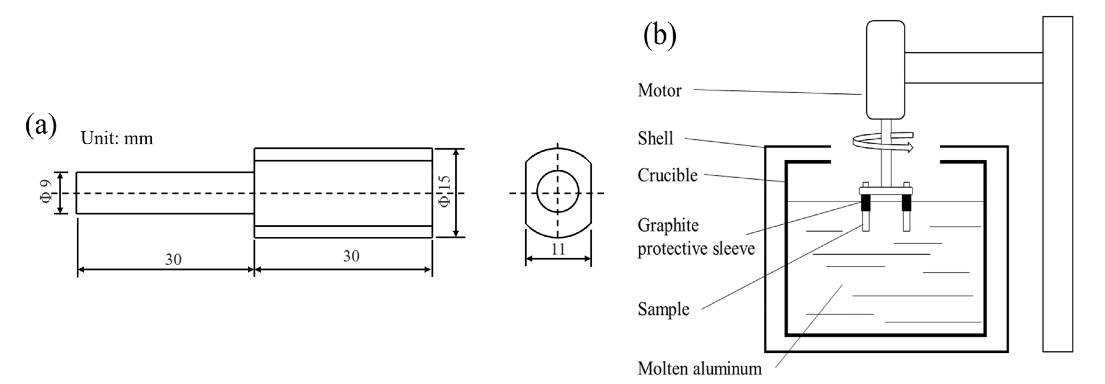
2.2. Methods
3. Results
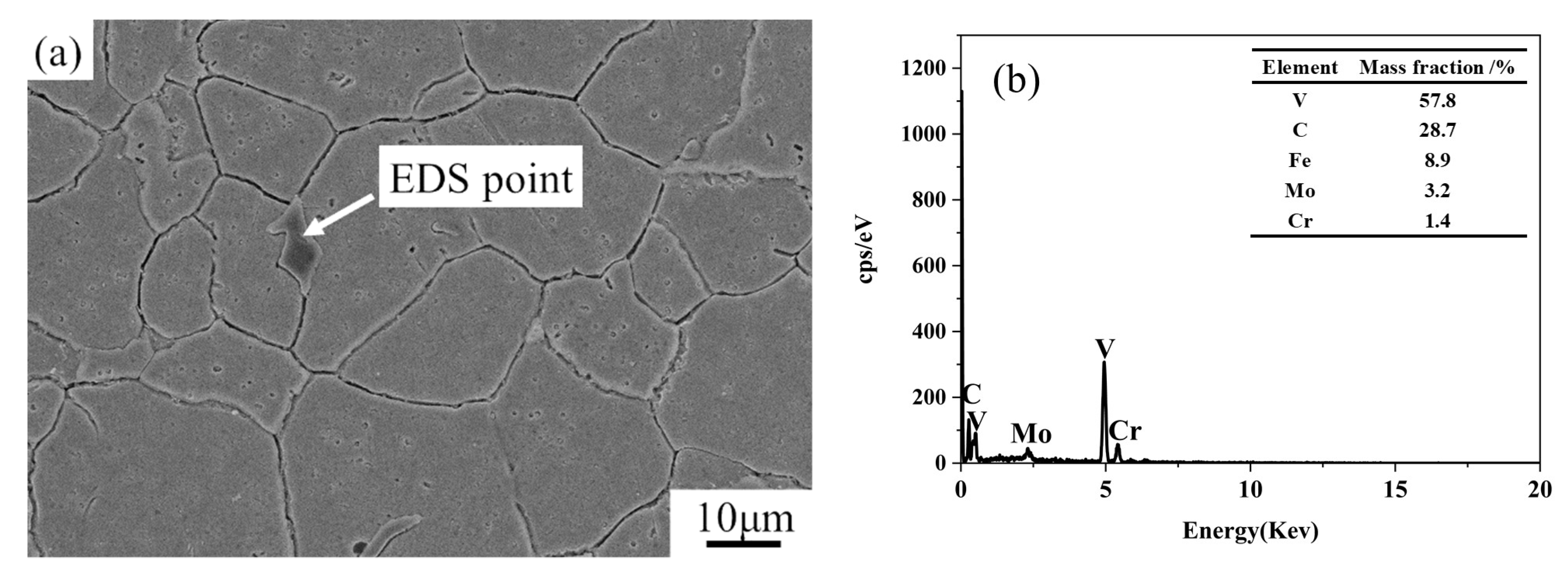
3.1. Microstructure of SDHA Steel
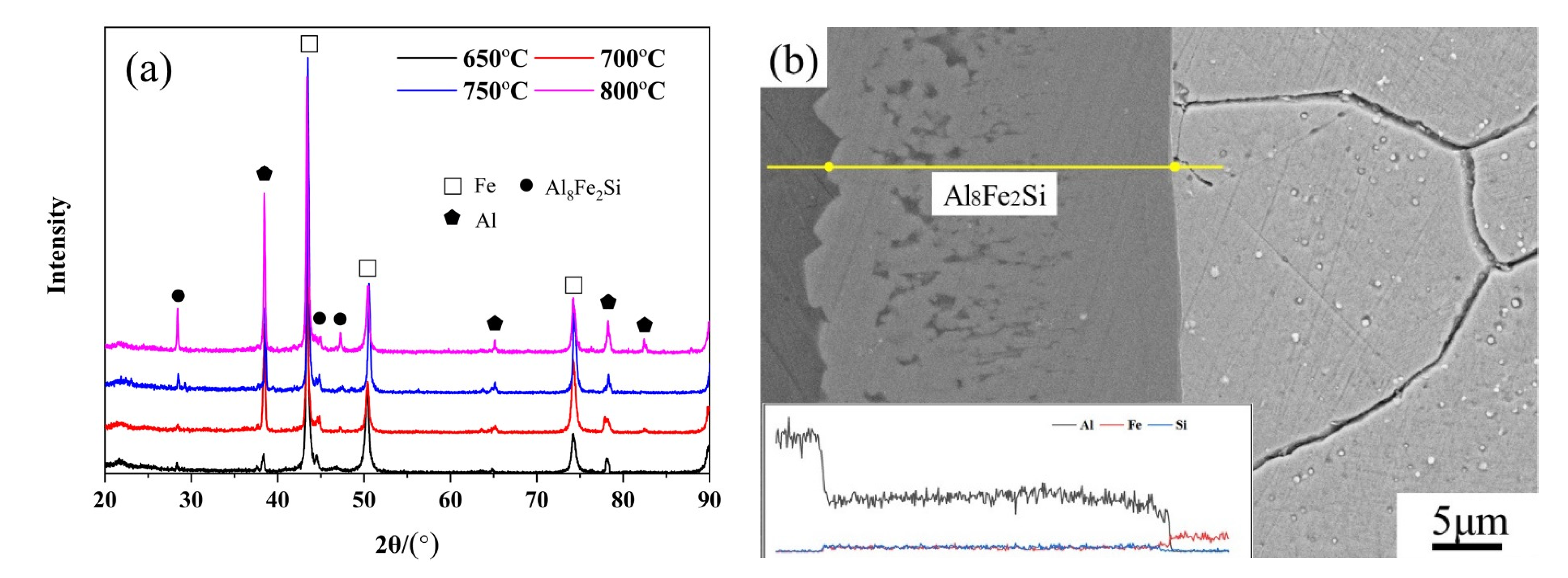
3.2. Phase Calibration of IMCs
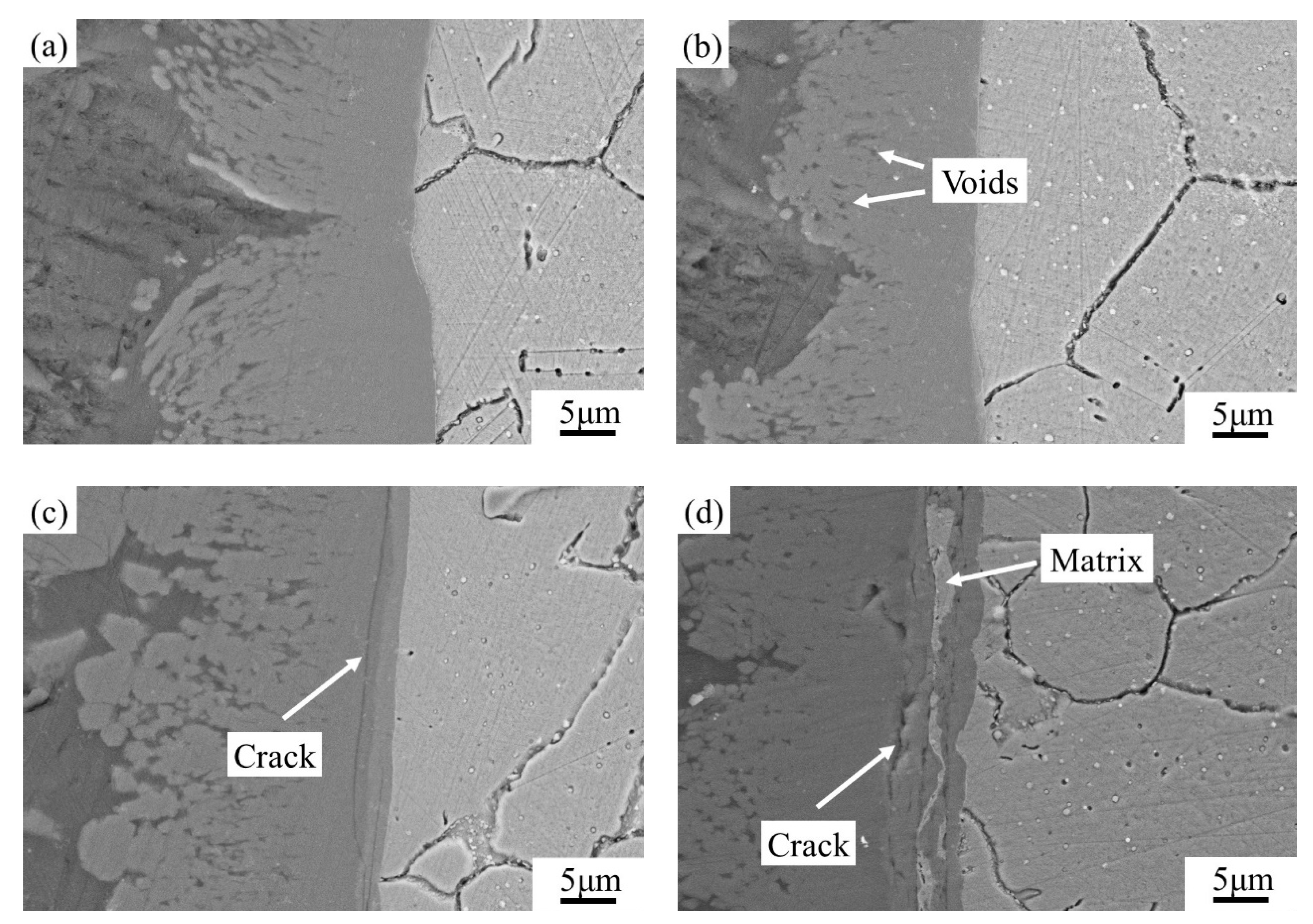
3.3. Dynamic Corrosion Morphology of IMCs
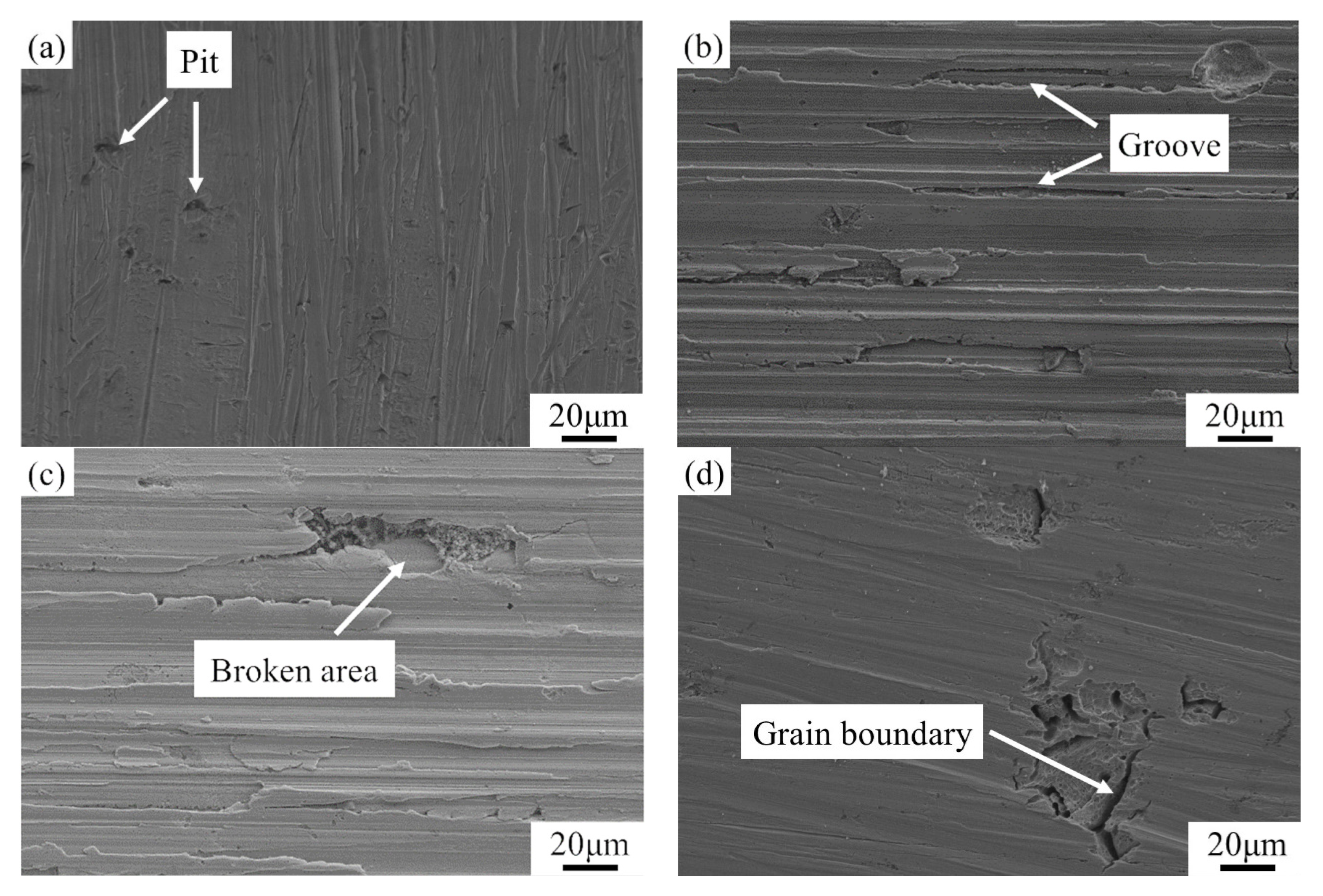
3.4. Surface Morphologies of the Matrix after Dynamic Corrosion
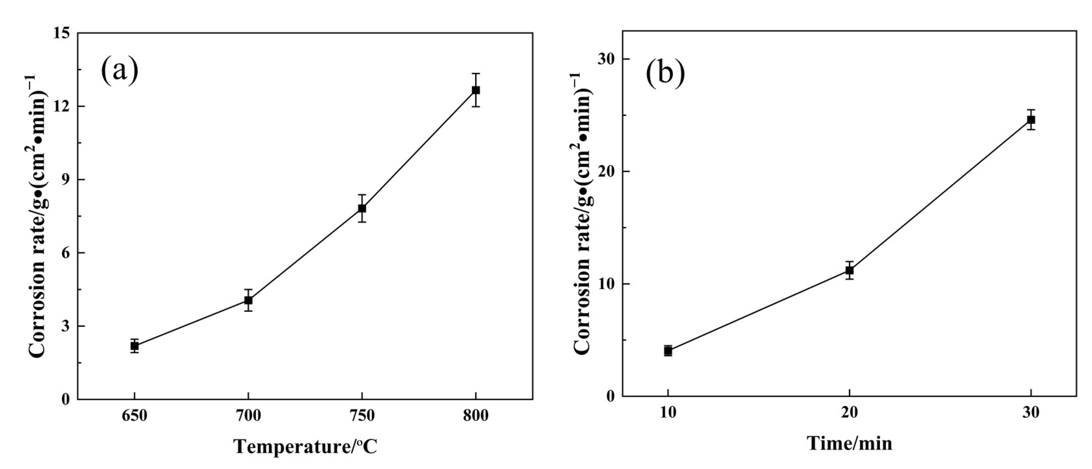
3.5. Dynamic Corrosion Rates
3.6. Growth Activation Energy of the IMCs
4. Discussion
4.1. The Effect of Carbides on Corrosion
4.2. Dynamic Corrosion Mechanism
5. Conclusions
- (1)
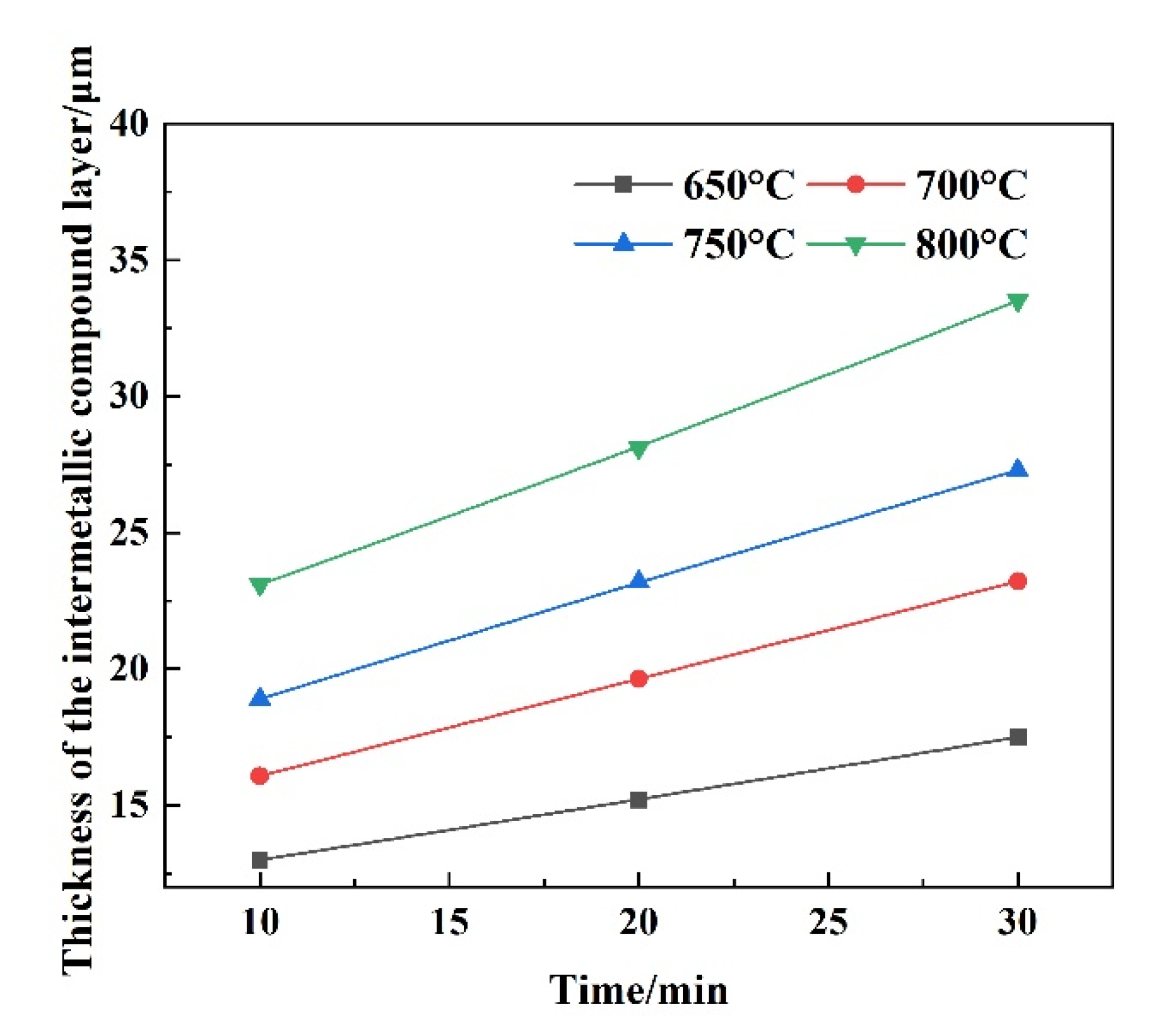
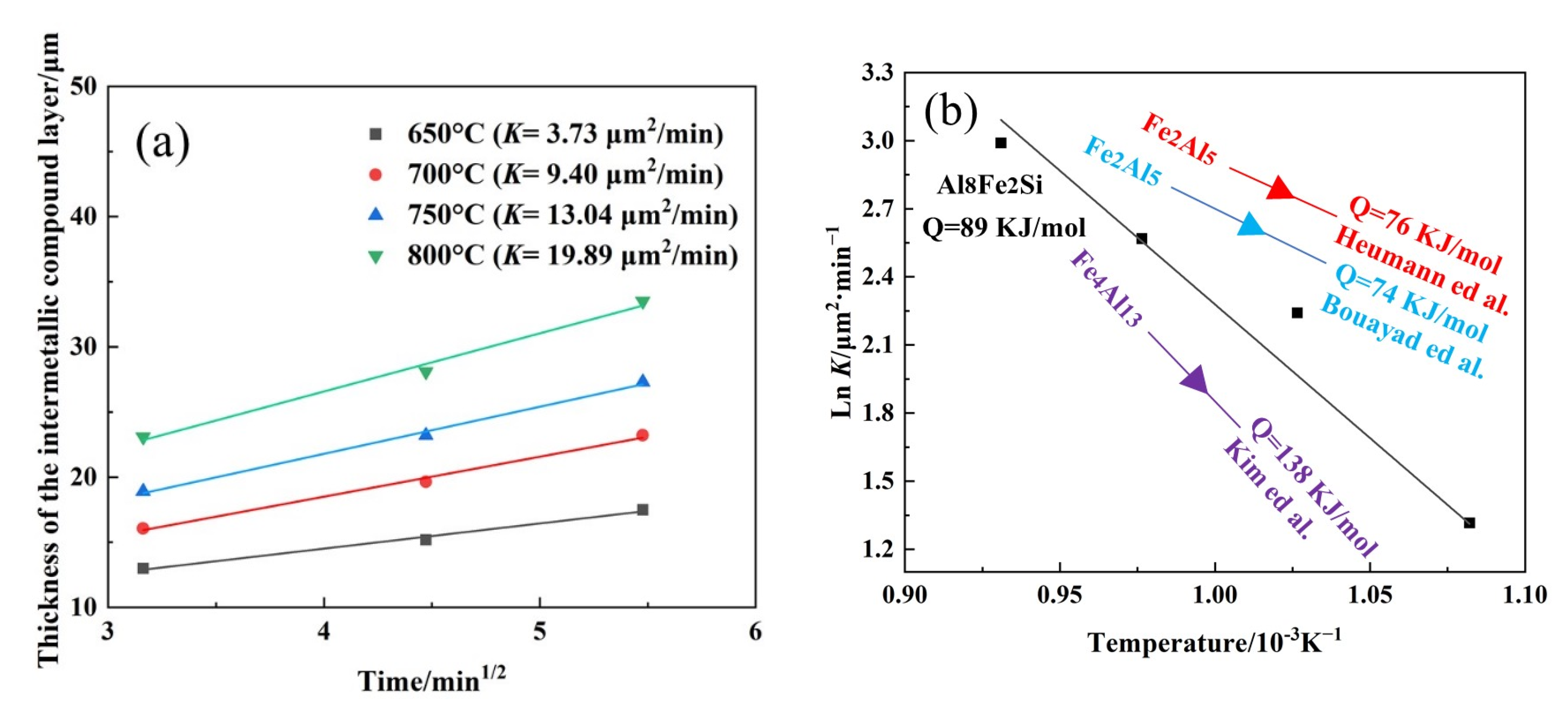
- During static immersion, the thickness of the IMC layer increases with increasing temperatures and holding times. The IMCs are identified as the Al8Fe2Si phase during corrosion. At temperatures from 650 °C to 800 °C, the kinetic constants of Al8Fe2Si increase from 3.73 μm2/min to 19.89 μm2/min. The growth activation energy of the Al8Fe2Si phase is calculated to be 89 kJ/mol.
- (2)
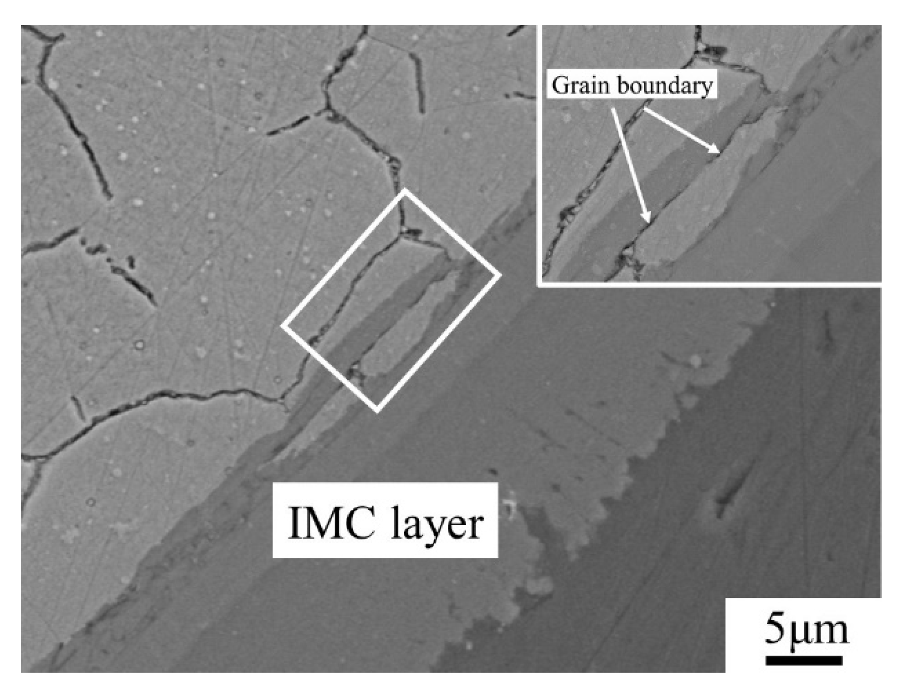
- The dynamic corrosion rate increases with an increase in corrosion temperatures; the dynamic corrosion rate is highest at 800 °C with a value of 12.67 g/(cm2∙min). At 800 °C, the diffusion reaction is preferentially carried out at the grain boundary. The formed IMCs with a poor bonding force lead to the spalling of the matrix under scouring force.
- (3)
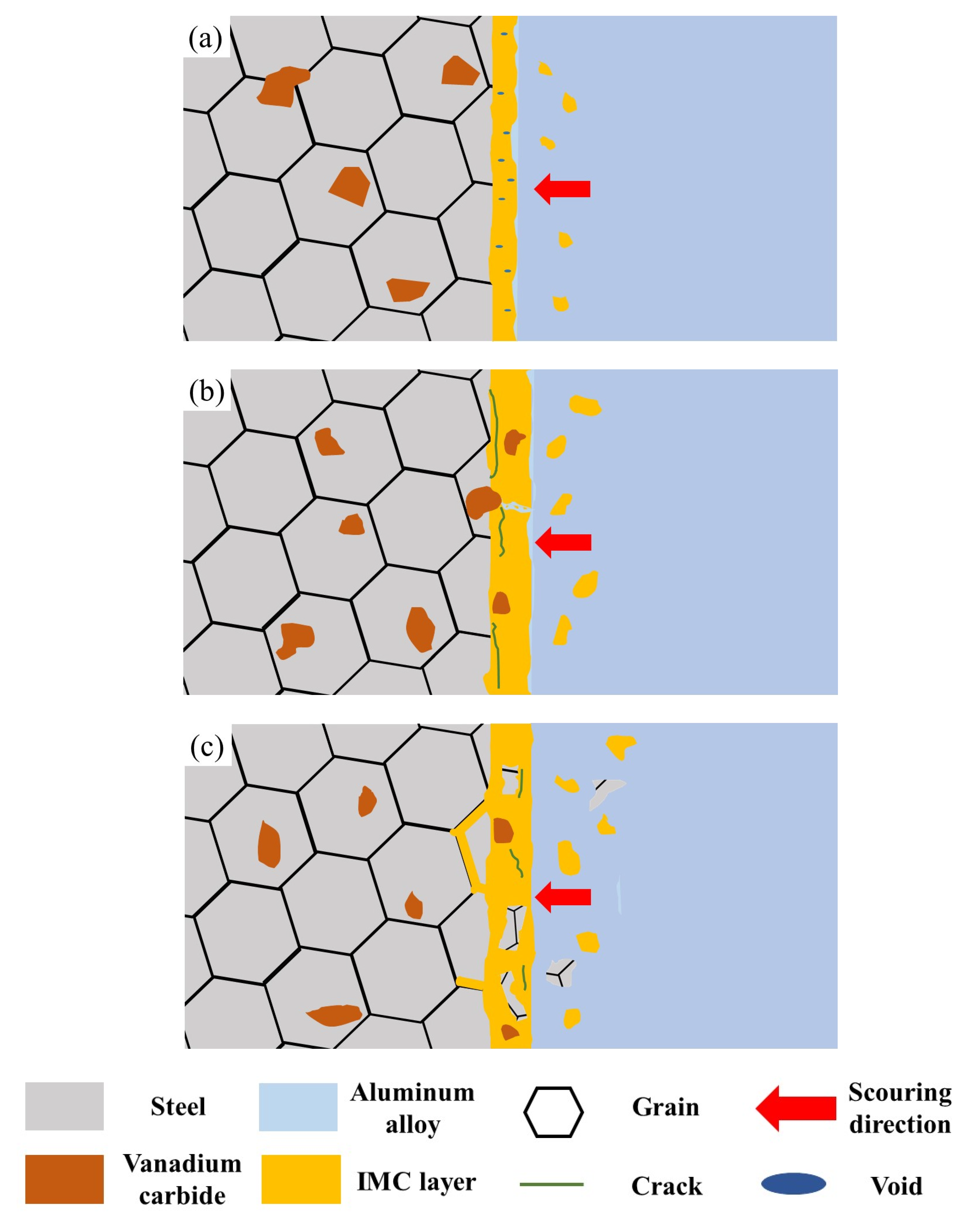
- Vanadium carbides in matrix with a lower dissolution rate can effectively inhibit the diffusion of Al and Si atoms. Additionally, a schematic diagram of the dynamic corrosion mechanism in molten aluminum alloy was proposed.
Author Contributions
Funding
Institutional Review Board Statement
Informed Consent Statement
Data Availability Statement
Conflicts of Interest
References
- Salonitis, K.; Jolly, M.; Pagone, E.; Papanikolaou, M. Life-Cycle and Energy Assessment of Automotive Component Manufacturing: The Dilemma Between Aluminum and Cast Iron. Energies 2019, 12, 2557. [Google Scholar] [CrossRef] [Green Version]
- Tisza, M.; Czinege, I. Comparative study of the application of steels and aluminium in lightweight production of automotive parts. Int. J. Lightweight Mater. Manuf. 2018, 1, 229–238. [Google Scholar] [CrossRef]
- Kan, M.; Ipek, O.; Koru, M. An Investigation into the Effect of Vacuum Conditions on the Filling Analysis of the Pressure Casting Process. Int. J. Metalcasting 2022. [Google Scholar] [CrossRef]
- Ding, R.G.; Yang, H.B.; Li, S.Z.; Hu, G.D.; Mo, J.H.; Chu, M.Q.; Paddea, S.J.; Zhang, S.Y.; Zhang, P.; Liu, Z.R.; et al. Failure analysis of H13 steel die for high pressure die casting Al alloy. Eng. Fail. Anal. 2021, 124, 105330. [Google Scholar] [CrossRef]
- Bhaskar, M.; Anand, G.; Nalluswamy, T.; Suresh, P. Die Life in Aluminium High-Pressure Die Casting Industries. J. Inst. Eng. Ser. D 2022. [Google Scholar] [CrossRef]
- Chen, Z.W. Formation and progression of die soldering during high pressure die casting. Mater. Sci. Eng. A 2005, 397, 356–369. [Google Scholar] [CrossRef]
- Kim, J.-H.; Kim, S.-Y.; Kang, C.-Y. Effect of phase difference on growth kinetic of alloy layer in aluminized and diffusion-treated 12% Cr heating resistant steels. Surf. Coat. Technol. 2014, 240, 387–392. [Google Scholar] [CrossRef]
- Zhang, X.; Li, X.; Chen, W. Interfacial reactions of duplex stainless steels with molten aluminum. Surf. Interface Anal. 2015, 47, 648–656. [Google Scholar] [CrossRef]
- Xu, G.; Wang, K.; Dong, X.; Jiang, H.; Wang, Q.; Ye, B.; Ding, W. Multiscale corrosion-resistance mechanisms of novel ferrous alloys in dynamic aluminum melts. Corros. Sci. 2020, 163, 108276. [Google Scholar] [CrossRef]
- Balloy, D.; Tissier, J.-C.; Giorgi, M.-L.; Briant, M. Corrosion Mechanisms of Steel and Cast Iron by Molten Aluminum. Metall. Mater. Trans. A 2010, 41, 2366–2376. [Google Scholar] [CrossRef]
- Hou, L.F.; Wei, Y.H.; Li, Y.G.; Liu, B.S.; Du, H.Y.; Guo, C.L. Erosion process analysis of die-casting inserts for magnesium alloy components. Eng. Fail. Anal. 2013, 33, 457–464. [Google Scholar] [CrossRef]
- Markežič, R.; Naglič, I.; Mole, N.; Šturm, R. Experimental and numerical analysis of failures on a die insert for high pressure die casting. Eng. Fail. Anal. 2019, 95, 171–180. [Google Scholar] [CrossRef]
- Joshi, V.; Srivastava, A.; Shivpuri, R. Intermetallic formation and its relation to interface mass loss and tribology in die casting dies. Wear 2004, 256, 1232–1235. [Google Scholar] [CrossRef]
- Dadic, Z.; Zivkovic, D.; Catipovic, N.; Marinic-Kragic, I. Influence of steel preheat temperature and molten casting alloy AlSi9Cu3(Fe) impact speed on wear of X38CrMoV5-1 steel in high pressure die casting conditions. Wear 2019, 424, 15–22. [Google Scholar] [CrossRef]
- Venkatesan, K.; Shivpuri, R. Experimental and numerical investigation of the effect of process parameters on the erosive wear of die casting dies. J. Mater. Eng. Perform. 1995, 4, 166–174. [Google Scholar] [CrossRef]
- Vachhani, H.; Rathod, M.; Shah, R. Dissolution and erosion behavior of AISI H13 shot sleeve in high pressure die casting process. Eng. Fail. Anal. 2019, 101, 206–214. [Google Scholar] [CrossRef]
- Yuan, B.; Liao, D.M.; Jiang, W.M.; Deng, H.; Li, G.Y. Investigation on corrosion mechanism of stirring paddles of different iron-based materials in ZL101 aluminum melt. J. Mater. Res. Technol. 2021, 13, 1992–2005. [Google Scholar] [CrossRef]
- Kim, S.W.; Durrant, G.; Lee, J.H.; Cantor, B. The effect of die geometry on the microstructure of indirect squeeze cast and gravity die cast 7050 (Al-6.2Zn-2.3Cu-2.3Mg) wrought Al alloy. J. Mater. Sci. 1999, 34, 1873–1883. [Google Scholar] [CrossRef]
- Qin, X.Y.; Su, Y.; Chen, J.; Liu, L.J.J. Finite element analysis for die casting parameters in high-pressure die casting process. China Foundry 2019, 16, 272–276. [Google Scholar] [CrossRef] [Green Version]
- Kobayashi, S.; Yakou, T. Control of intermetallic compound layers at interface between steel and aluminum by diffusion-treatment. Mater. Sci. Eng. A 2002, 338, 44–53. [Google Scholar] [CrossRef]
- Cheng, W.-J.; Wang, C.-J. Study of microstructure and phase evolution of hot-dipped aluminide mild steel during high-temperature diffusion using electron backscatter diffraction. Appl. Surf. Sci. 2011, 257, 4663–4668. [Google Scholar] [CrossRef]
- Jeong, E.-W.; Hui, K.N.; Bae, D.-H.; Bae, D.-S.; Cho, Y.-R. Identification of the intermetallic compound layer formed at the interface of roll-bonded aluminum-clad steel by thermal annealing. Met. Mater. Int. 2014, 20, 499–502. [Google Scholar] [CrossRef]
- Kim, J.-H.; Wang, J.-P.; Kang, C.-Y. Effect of aluminizing treatment on the oxidation properties of 12Cr heat resisting steel. Met. Mater. Int. 2011, 17, 931–935. [Google Scholar] [CrossRef]
- Zhu, Y.; Schwam, D.; Wallace, J.F.; Birceanu, S. Evaluation of soldering, washout and thermal fatigue resistance of advanced metal materials for aluminum die-casting dies. Mater. Sci. Eng. A 2004, 379, 420–431. [Google Scholar] [CrossRef]
- Shankar, S.; Apelian, D. Die soldering: Effect of process parameters and alloy characteristics on soldering in the pressure die casting process. Int. J. Cast Met. Res. 2002, 15, 103–116. [Google Scholar] [CrossRef]
- Shivpuri, R.; Yu, M.; Venkatesan, K.; Chu, Y.L. A study of erosion in die casting dies by a multiple pin accelerated erosion test. J. Mater. Eng. Perform. 1995, 4, 145–153. [Google Scholar] [CrossRef]
- Ling, Z.; Chen, W.; Xu, W.; Zhang, X.; Lu, T.; Liu, J. The Influence of A Mo Addition on the Interfacial Morphologies and Corrosion Resistances of Novel Fe-Cr-B Alloys Immersed in Molten Aluminum. Materials 2019, 12, 256. [Google Scholar] [CrossRef] [Green Version]
- Bouayad, A.; Gerometta, C.; Belkebir, A.; Ambari, A. Kinetic interactions between solid iron and molten aluminium. Mater. Sci. Eng. A 2003, 363, 53–61. [Google Scholar] [CrossRef]
- Cheng, W.J.; Wang, C.J. Growth of intermetallic layer in the aluminide mild steel during hot-dipping. Surf. Coat. Technol. 2009, 204, 824–828. [Google Scholar] [CrossRef]
- Xu, G.; Wang, K.; Dong, X.; Yang, L.; Ebrahimi, M.; Jiang, H.; Wang, Q.; Ding, W. Review on corrosion resistance of mild steels in liquid aluminum. J. Mater. Sci. Technol. 2021, 71, 12–22. [Google Scholar] [CrossRef]
- Ei-Mahallawy, N.A.; Taha, M.A.; Shady, M.A.; Ei-Sissi, A.R.; Attia, A.N.; Reif, W. Analysis of coating layer formedon steel strips during aluminizing by hot dipping in Al-Si baths. Mater. Sci. Technol. 1997, 13, 832–840. [Google Scholar] [CrossRef]
- Tanaka, Y.; Kajihara, M. Kinetics of isothermal reactive diffusion between solid Fe and liquid Al. J. Mater. Sci. 2010, 45, 5676–5684. [Google Scholar] [CrossRef]
- Heumann, T.; Dittrich, S. Structure character of the Fe2Al5 intermetallics compound in hot dip aluminizing process. Z. Met. 1959, 50, 617–623. [Google Scholar]
- Bouché, K.; Barbier, F.; Coulet, A. Intermetallic compound layer growth between solid iron and molten aluminium. Mater. Sci. Eng. A 1998, 249, 167–175. [Google Scholar] [CrossRef]
- Kim, J.-M.; Shin, K.; Shin, J.-S. Microstructural Evolution and Growth of Intermetallic Compounds at the Interface between Solid Cast Iron and Liquid Al–Si Alloy. Metals 2020, 10, 759. [Google Scholar] [CrossRef]
- Rezaei, H.; Akbarpour, M.R.; Shahverdi, H.R. Effects of Interfacial Layers Fracture on the Dissolution Mechanism of Solid Fe in Liquid Al. Jom 2015, 67, 1443–1450. [Google Scholar] [CrossRef]
- Yeremenko, V.N.; Natanzon, Y.V.; Dybkov, V.I. The effect of dissolution on the growth of the Fe2Al5 interlayer in the solid iron -liquid aluminium system. J. Mater. Sci. 1981, 16, 1748–1756. [Google Scholar] [CrossRef]


| C | Si | Mn | Cr | Mo | V | P | S | Fe |
|---|---|---|---|---|---|---|---|---|
| 0.62 | 0.81 | 10.45 | 3.10 | 1.69 | 1.83 | 0.012 | 0.0140 | Bal. |
| Pb | Ti | Zn | Si | Mn | Fe | Mg | Cu | Al |
|---|---|---|---|---|---|---|---|---|
| 0.035 | 0.064 | 0.87 | 10.60 | 0.16 | 0.76 | 0.22 | 1.74 | Bal. |
| Number | Temperature/°C | Time/Min | Number | Temperature/°C | Time/Min |
|---|---|---|---|---|---|
| 1 | 650 | 10 | 4 | 800 | 10 |
| 2 | 700 | 10 | 5 | 700 | 20 |
| 3 | 750 | 10 | 6 | 700 | 30 |
| Number | Temperature/°C | Time/Min | Number | Temperature/°C | Time/Min |
|---|---|---|---|---|---|
| 1 | 650 | 10 | 7 | 750 | 10 |
| 2 | 650 | 20 | 8 | 750 | 20 |
| 3 | 650 | 30 | 9 | 750 | 30 |
| 4 | 700 | 10 | 10 | 800 | 10 |
| 5 | 700 | 20 | 11 | 800 | 20 |
| 6 | 700 | 30 | 12 | 800 | 30 |
Publisher’s Note: MDPI stays neutral with regard to jurisdictional claims in published maps and institutional affiliations. |
© 2022 by the authors. Licensee MDPI, Basel, Switzerland. This article is an open access article distributed under the terms and conditions of the Creative Commons Attribution (CC BY) license (https://creativecommons.org/licenses/by/4.0/).
Share and Cite
Bai, Z.; Su, N.; Yang, H.; Wu, X. Research on the Corrosion Behaviors of Austenitic Steel in Molten Aluminum Alloy. Coatings 2022, 12, 551. https://doi.org/10.3390/coatings12050551
Bai Z, Su N, Yang H, Wu X. Research on the Corrosion Behaviors of Austenitic Steel in Molten Aluminum Alloy. Coatings. 2022; 12(5):551. https://doi.org/10.3390/coatings12050551
Chicago/Turabian StyleBai, Zhixiong, Ning Su, Hang Yang, and Xiaochun Wu. 2022. "Research on the Corrosion Behaviors of Austenitic Steel in Molten Aluminum Alloy" Coatings 12, no. 5: 551. https://doi.org/10.3390/coatings12050551
APA StyleBai, Z., Su, N., Yang, H., & Wu, X. (2022). Research on the Corrosion Behaviors of Austenitic Steel in Molten Aluminum Alloy. Coatings, 12(5), 551. https://doi.org/10.3390/coatings12050551