Article

Microstructure, Mechanical, and Electrochemical Properties of SiC Particle Reinforced CoCrFeNiCu High-Entropy Alloy Coatings

College of Materials Science and Engineering, Xi’an University of Science and Technology, Xi’an 710054, China
*
Author to whom correspondence should be addressed.
Coatings 2022, 12(4), 519; https://doi.org/10.3390/coatings12040519
Submission received: 10 March 2022 / Revised: 20 March 2022 / Accepted: 8 April 2022 / Published: 11 April 2022

Abstract

:
SiC particle reinforced CoCrFeNiCu high-entropy alloy (HEA) coatings (CoCrFeNiCu(SiC)x, x = 0, 5, 10, 15 wt%) were successfully fabricated on 316L stainless steel via laser cladding technique. The effects of SiC particles on the microstructure, mechanical, and electrochemical properties of CoCrFeNiCu HEA were investigated. The results showed that the as-fabricated CoCrFeNiCu(SiC)x HEA coatings is a FCC structure, and a secondary phase formed of Cr7C3 at the grain boundaries. Grain boundary strengthening enhances the mechanical properties of CoCrFeNiCu(SiC)x HEA coatings. Especially for CoCrFeNiCu(SiC)15 HEA coatings, the microhardness, wear weight, and friction coefficient were 568.4 HV, 0.9 mg, and 0.35, respectively. With the increasing of SiC content, the corrosion resistance of CoCrFeNiCu(SiC)x HEA coatings was enhanced in 3.5% NaCl solution. The CoCrFeNiCu(SiC)10 coatings showed better performance than others when they were evaluated for corrosion. These results indicated that the CoCrFeNiCu(SiC)x HEA coatings could significantly enhance the wear, friction, and corrosion resistance properties of the 316L stainless steel.

1. Introduction

In 2004, a special alloy named high-entropy alloy (HEA) was first proposed by Yeh et al., which attracted widespread attention [1]. HEAs are defined as a kind of alloy material containing 5 to 13 principal alloying elements, and the molar content of each component is between 5 and 35 at % [2,3]. HEAs have been shown to have superior lattice distortion and configurational entropy, and display “cocktail” and sluggish diffusion effects, demonstrating they have very stable structure as well as good mechanical properties. HEAs have excellent properties, such as high strength properties [4], high-temperature performance [5], excellent wear [6], and desirable corrosion resistance [7], which are widely used in aerospace, marine materials, chemical, and electronic communications.
Due to the excellent mechanical and corrosion resistance properties of HEAs, they can also be used as protective coatings for steels, metals, or alloys to increase their service life. Jiang et al. [8] have prepared TiZrAlNbCo HEA coatings to improve the hardness and corrosion resistance of Ti-6Al-4V substrates by laser cladding. Abhijith et al. [9] reported TiNbMoMnFe HEA coatings with good hydrophobicity and high corrosion resistance, which was prepared on 304L stainless steel substrate by high-velocity oxygen-fuel thermal spraying technology. However, the properties of the coatings cannot fully meet the needs of application, and they are still necessary to be further improved. Recently, researchers have focused their attention to improving HEA coating properties by adding some ceramic reinforcing particles. For instance, Zhang et al. [10] added 10 vol% TiC into FeCoNiCu2.0, and the optimal ultimate tensile strength of the alloys increased from 473 MPa to 698 MPa. Bao et al. [11] added 20 wt% WC into FeCoCrNiB0.2, improving the Vickers hardness and the cavitation erosion resistance (Re) of the FeCoCrNiB0.2 HEA. The TiN-Al2O3-Cr2B was added to CoCrFeMnNi by Zhang et al. [12]. The multiphase ceramics acted as a disincentive to the adhesive wear of the composite coating and improved the wear resistance of the composite coating. Among the various ceramic reinforcement particles, SiC was an excellent ceramic reinforcement due to its high hardness, outstanding wear resistance, excellent thermal conductivity, and high temperature oxidation resistance, which were commonly selected as strengthening phase in metallic materials. Qu et al. [13] investigated the effect of nano-SiC content addition on the microstructures and mechanical properties of Al0.6CrFe2Ni2 high entropy alloy which were prepared by a vacuum arc melting furnace. This particular study revealed that the Cr7C3 particles were found in the grain boundaries due to the decomposition of SiC in high temperature, and the Cr7C3 particles can improve the mechanical properties of as-cast Al0.6CrFe2Ni2 HEA without reducing the plasticity effectively. Szklarz et al. [14] studied the influence of the addition of nano-SiC on the electrochemical performance of mechanical alloying combined with Hot Isostatic Pressing prepared CoCrFeMnNi HEA, indicating that the addition of SiC increased the yield stress and hardness of the alloy, and enhanced the chemical and electrochemical corrosion resistance of the alloy.
Up to the present, some varieties of techniques have been utilized to prepare HEA coatings, such as magnetron sputtering [15], vapor deposition [16], plasma spraying [17], etc. However, these methods are limited in their application due to the poor metallurgical adhesion between the substrate and the coatings. Laser cladding is widely utilized to prepare the HEA coatings, because of their outstanding advantages such as high-energy density [18], material and time saving [19], environment-friendly [20], fine and uniform microstructure [21], strong adhesive bonding [22], and little damage to the substrate surface [23]. Therefore, laser cladding has become the main method for preparing HEA coatings.
In this paper, SiC particles refenced CoCrFeNiCu (CoCrFeNiCu(SiC)x, x = 0, 5, 10, and 15 wt%) HEA coatings were successfully prepared on 316L stainless steel via laser cladding technology. The phase structures, morphologies, and element distribution of the coatings were characterized. In addition, the mechanical and electrochemical properties were also investigated. The results indicated that the as-prepared HEA coating can effectively protect the substrates well.

2. Experimental Section

2.1. Raw Materials and the Fabrication of the CoCrFeNiCu(SiC)x HEA Coatings

316L stainless steel with the size of 30 mm × 60 mm × 10 mm was selected as the substrate and removed the surface contaminants and oxide scale by SiC abrasive paper. The powders of Co, Cr, Fe, Ni, and Cu (purity 99.5%, the particle size in the range of 45–90 μm) were chosen as the raw materials to prepare CoCrFeNiCu HEA coatings. SiC powder (purity 99.5%) with a size of about 13 μm was used as an additive to increase the mechanical and electrochemical properties of CoCrFeNiCu HEA coatings. The amount of SiC additive are 0 wt%, 5 wt%, 10 wt%, and 15 wt%, which are named as CoCrFeNiCu, CoCrFeNiCu(SiC)5, CoCrFeNiCu(SiC)10, and CoCrFeNiCu(SiC)15, respectively.
Firstly, the five raw materials were weighted with the molar ratio of 1:1:1:1:1 to prepare the HEA coatings. Then, SiC powders were added into the after weighted powders with the corresponding amounts, respectively. Finally, the four mixtures with different SiC contents were mixed by a ball-milling machine for 4 h to obtain pre-cladding powders. Stainless steel balls with a diameter of 10 mm were used for auxiliary grinding in the ball-milling process, and the volume ratio of ball to powder was 2:1. The ethanol was chosen as the ball milling medium. The as-obtained slurry was dried in an oven with the temperature of 100 °C for 8 h to obtain pre-cladding powders. Then, the powders were spread on the 316 L stainless steel at room temperature with a thickness of about 15 mm. BS-OFE-3000-20-4L laser surface treatment equipment was utilized to clad the powder on the substrate to prepare CoCrFeNiCu(SiC)x HEA coatings under an argon atmosphere protection. The optimized process parameters of the laser cladding are shown in Table 1.

2.2. Characterization Methods of CoCrFeNiCu(SiC)x High-Entropy Alloy Coatings

For the morphologies, phase, and properties testing, the as-prepared samples were cut with the size of 10mm × 10mm × 10 mm by an EDM cutting machine(Dingxing CNC, Taizhou, China). The phase of the CoCrFeNiCu(SiC)x HEA coatings were analyzed by an X-ray diffractometer (XRD, D8 Advance, BRUKER, Karlsruhe, Germany) with Cu Kα radiation. Data were digitally recorded in a continuous scan in the range of angle (2θ) from 30° to 100° with a scanning rate of 50·min−1. The surfaces of the samples were polished and etched with aqua regia (HCl:HNO3 = 3:1) for 10 s to analyze the morphologies by a thermal field emission scanning electron microscope (SEM, FEI Quanta FEG250, FEI Company, Hillsboro, OR, USA). The elemental analysis was conducted by energy dispersive spectroscopy (EDS, EDAX, OR, USA).
The hardness of the coating was measured by a microhardness tester (HV-1000, JuHui, ShangHai, China), where the input load was 0.2 N and the loading time was 10 s. The MFT-R4000 reciprocating friction and wear tester (HQ-004(MFT-R4000), ZhongKeKaiTeKe, LanZhou, China) was used to carry out dry sliding reciprocating friction and wear test on HEA coating. The worn sample size was 10 mm× 15 mm × 10 mm. The friction pair was a GCr15 ball with diameter (2R) of 6 mm. The wear test lasted 30 min, the test load (P) was 20 N, the stroke length was 10 mm, and the reciprocating frequency was 5 Hz. The wear test of the high-entropy alloy coatings was repeated three times. The coefficient of friction is continuously recorded by the test system, and the quality of wear is measured by an electronic balance.
Potentiodynamic polarization measurements (CS2350, KeSiTe, Wuhan, China) were used to study the corrosion behavior of the coating. In a typical three-electrode cell setup we had the specimen as a working electrode (WE), a silver chloride reference electrode (RE), and a platinum counter electrode (CE). The electrochemical polarization measurements were conducted in 3.5% NaCl solution. The working surface of the sample used for measurement is about 1 cm2. The specimen was scanned potentiodynamically at a rate of 2 mv/s from the initial potential of −1.5 V versus open circuit potential to the final potential of 1.5 V. The Tafel curves were used to extrapolate the corrosion parameters.

3. Results and Discussion

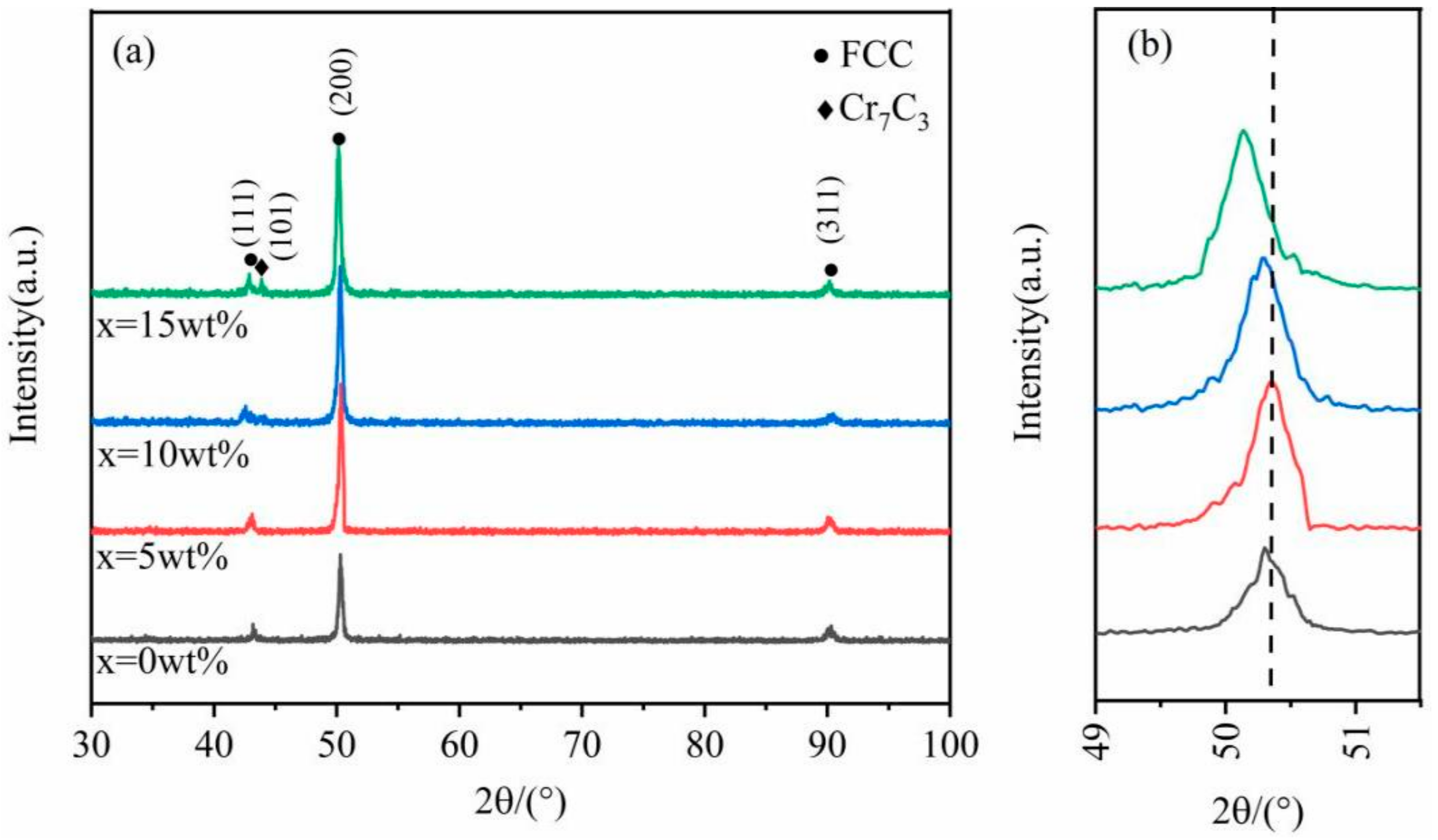
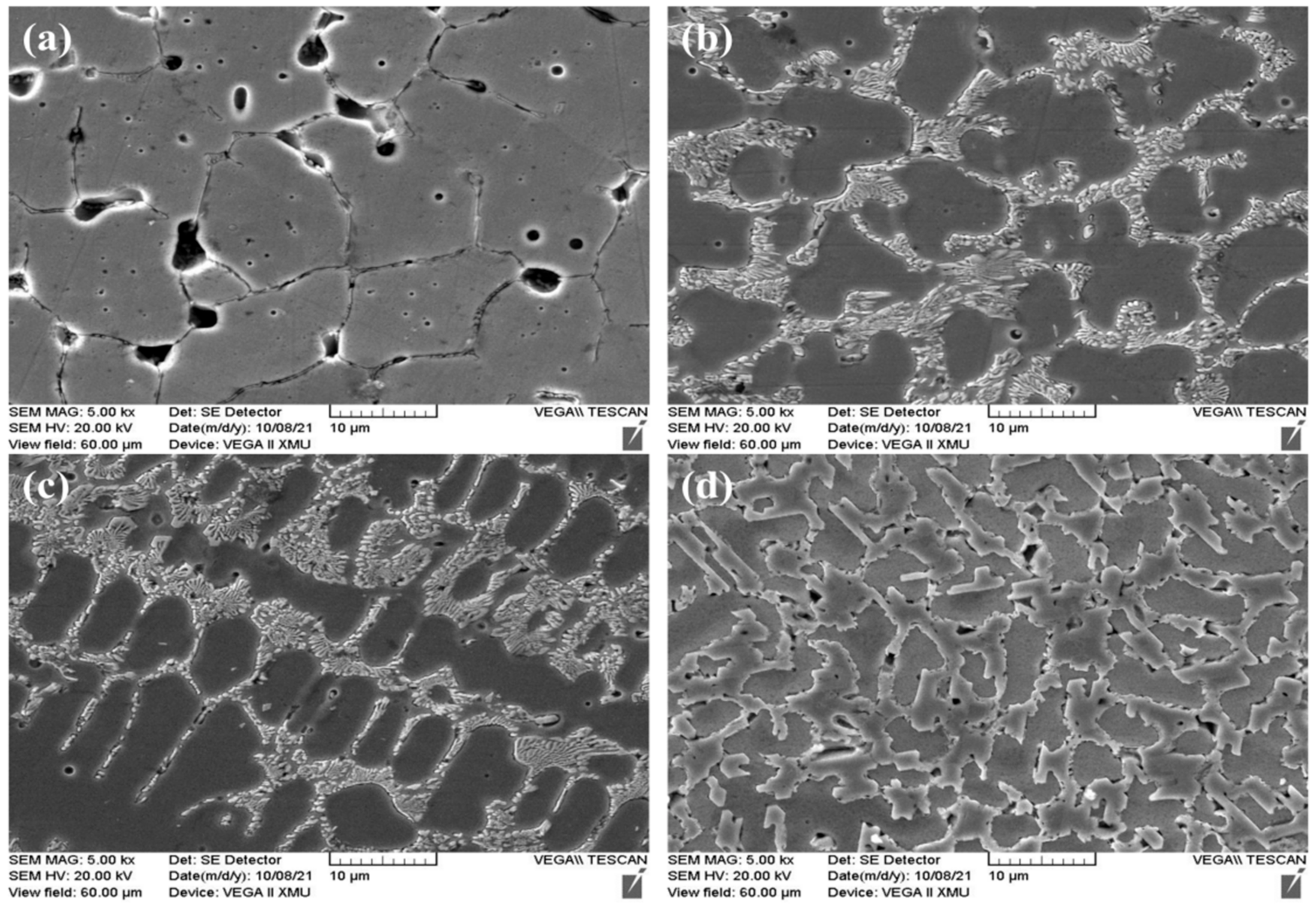
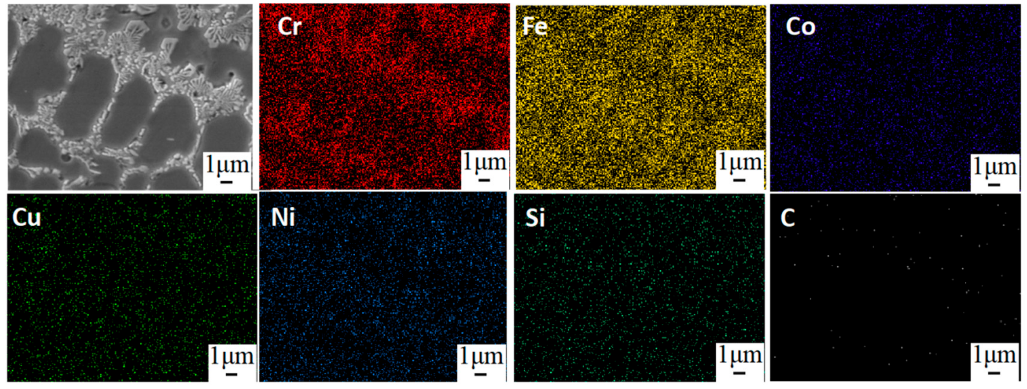
3.1. Phases and Morphologies of the CoCrFeNiCu(SiC)x High-Entropy Alloy Coatings

Figure 1 shows the XRD patterns of CoCrFeNiCu(SiC)x HEA coatings. As can be seen, the as-prepared CoCrFeNiCu(SiC)x is a FCC structure. The high entropy effect can inhibit the formation of intermetallic compounds and promote the formation of simple solid solutions structure and amorphous [24]. At the same time, the formation of the FCC structure is believed to be due to the high cooling rate of the laser cladding process. There are no diffraction peaks of SiC phase with all contents (Figure 1a). That is because the SiC decomposed during the laser cladding process. However, a new phase of Cr7C3 appeared in the CoCrFeNiCu(SiC)5, CoCrFeNiCu(SiC)10, and CoCrFeNiCu(SiC)15. It can be ascribed to the C reacting with Cr to form Cr7C3 [25]. The same phenomenon has also been reported during the process of TiC added into CoCrFeNi alloys [26]. Usually, the chemical reaction is influenced by the mixing enthalpy (ΔHm) between two elements. The lower the value of the ΔHm, the easier the reaction happened. For this study, the value of ΔHm between C and Cr is −61 kJ∙mol−1, which is smaller than that of C and other elements in the CoCrFeNiCu(SiC)x system. Therefore, the C and Cr will react to form Cr7C3 as the reaction of 7Cr + 3C → Cr7C3 at a high temperature. The Gibbs free energy (ΔG) of this reaction is about −136.6 kJ/mol [27]. According to the Bragg formula and the interplanar spacing formula, the lattice constants of each coating of the high-entropy alloy are calculated to be 0.3625, 0.3617, 0.3629, and 0.3640 nm, respectively. As can be seen in Figure 1b, the (200) diffraction peak shifts toward higher Bragg diffraction angles when x ≥ 5 wt%. The lattice parameters initially decreased as x increased, which is associated with the shift of C and Si, which have small atomic sizes across diverse components of the CoCrFeNiCu(SiC)x HEAs, into the FCC phase, causing a large distortion of the lattice and a reduction in the lattice parameters. However, as the SiC content continues to increase, the lattice constant of the FCC phase increases, resulting in intensified crystal distortion, larger interplanar spacing, and lattice expansion, so the solid solution strengthening effect is enhanced. As a consequence, the lattice constant of the CoCrFeNiCu(SiC)x HEAs showed an initially decreasing, but later increasing, trend as the SiC was increased.
Figure 2 shows the morphologies of the CoCrFeNiCu(SiC)x HEA coatings. As can be seen, there are lots of pores on the surface of the CoCrFeNiCu coating, which formed during the rapid solidification process of the coating. Especially for the grain boundaries, the big pores easily exist. The small pores exist in the inner of the crystal grain. The grain size of the CoCrFeNiCu coating is approximately 8~12 μm. When the x = 5 wt%, it finds that a second phase is precipitated at the grain boundaries (Figure 2b), and the pores, which are at the grain boundaries, have already been filled. These precipitated phases are pinned to the grain boundaries to prevent further growth of grains. Obviously, with the value of SiC increasing, the size of the grain decreased (Figure 2c,d).
As aforementioned, SiC has decomposed into Si and C during the laser cladding process. The C would react with Cr in the high-entropy alloys to form Cr7C3. Hence, the second phase may be the Cr7C3. Figure 3 shows the EDS mapping of the CoCrFeNiCu(SiC)10 high-entropy alloy coatings. The high-entropy alloy components are distributed uniformly on the surface of the coatings, except the elements of Cr and C. These two elements are enriched in the position of the precipitated phase, indicating that it is composed of Cr and C elements. Combined with the results of XRD, it can be recognized that the precipitated phase is Cr7C3.

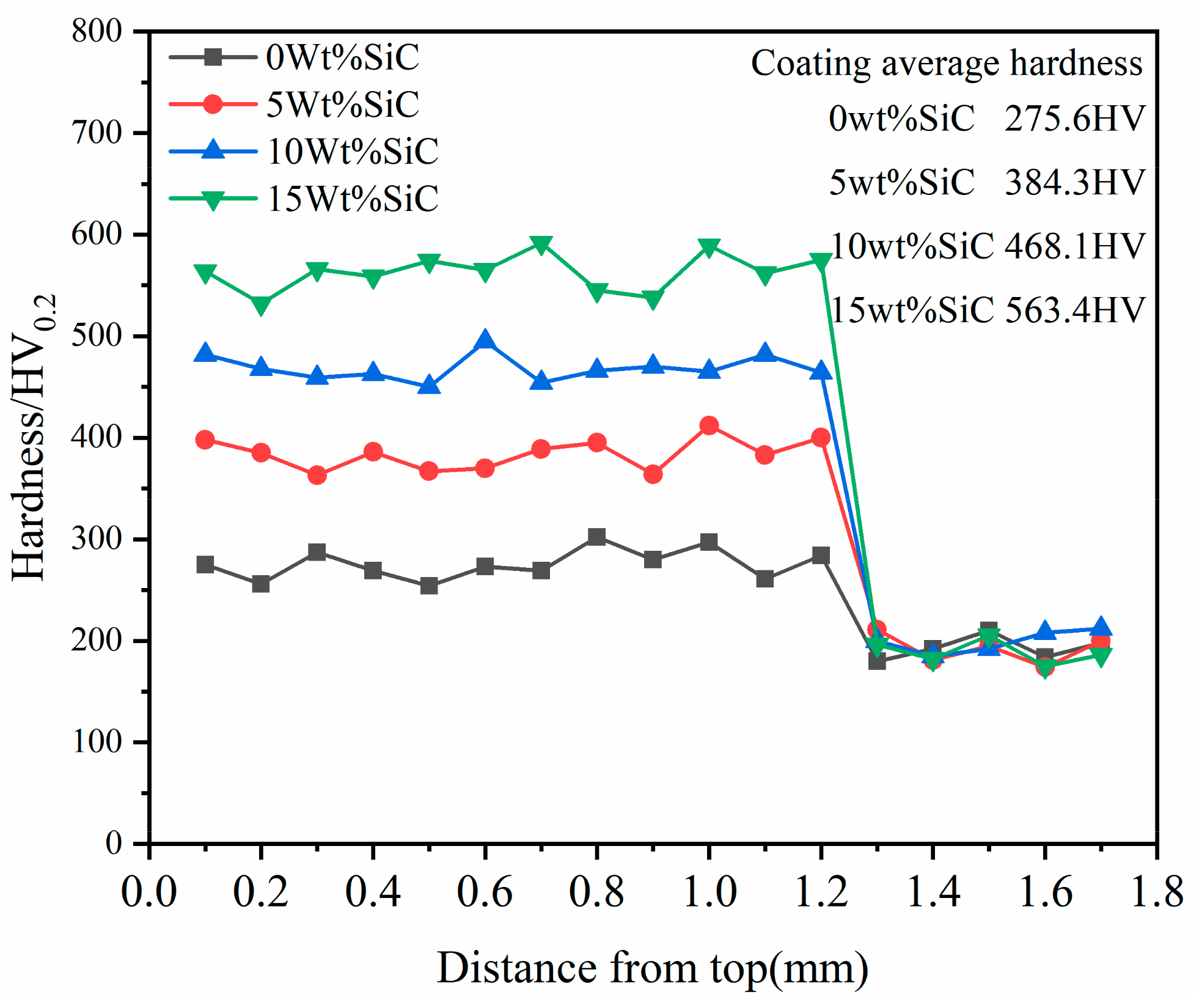
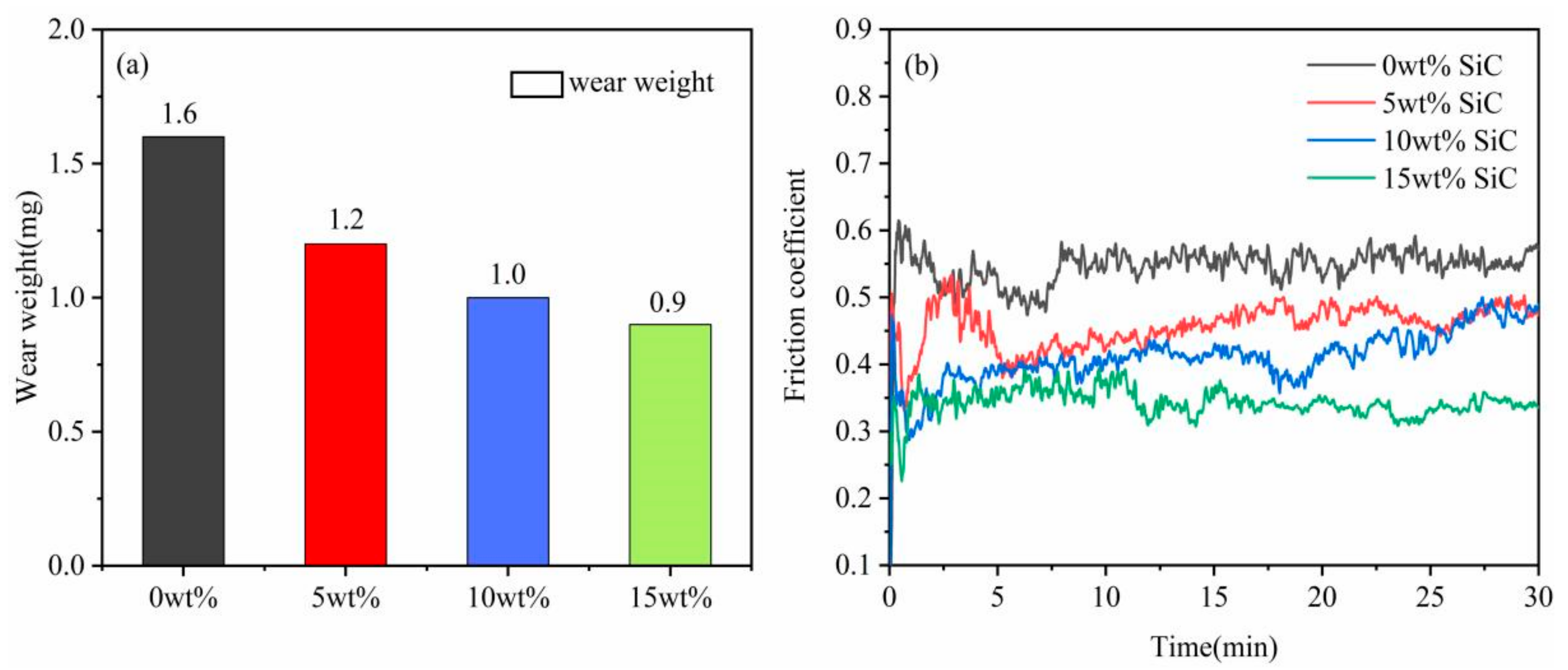
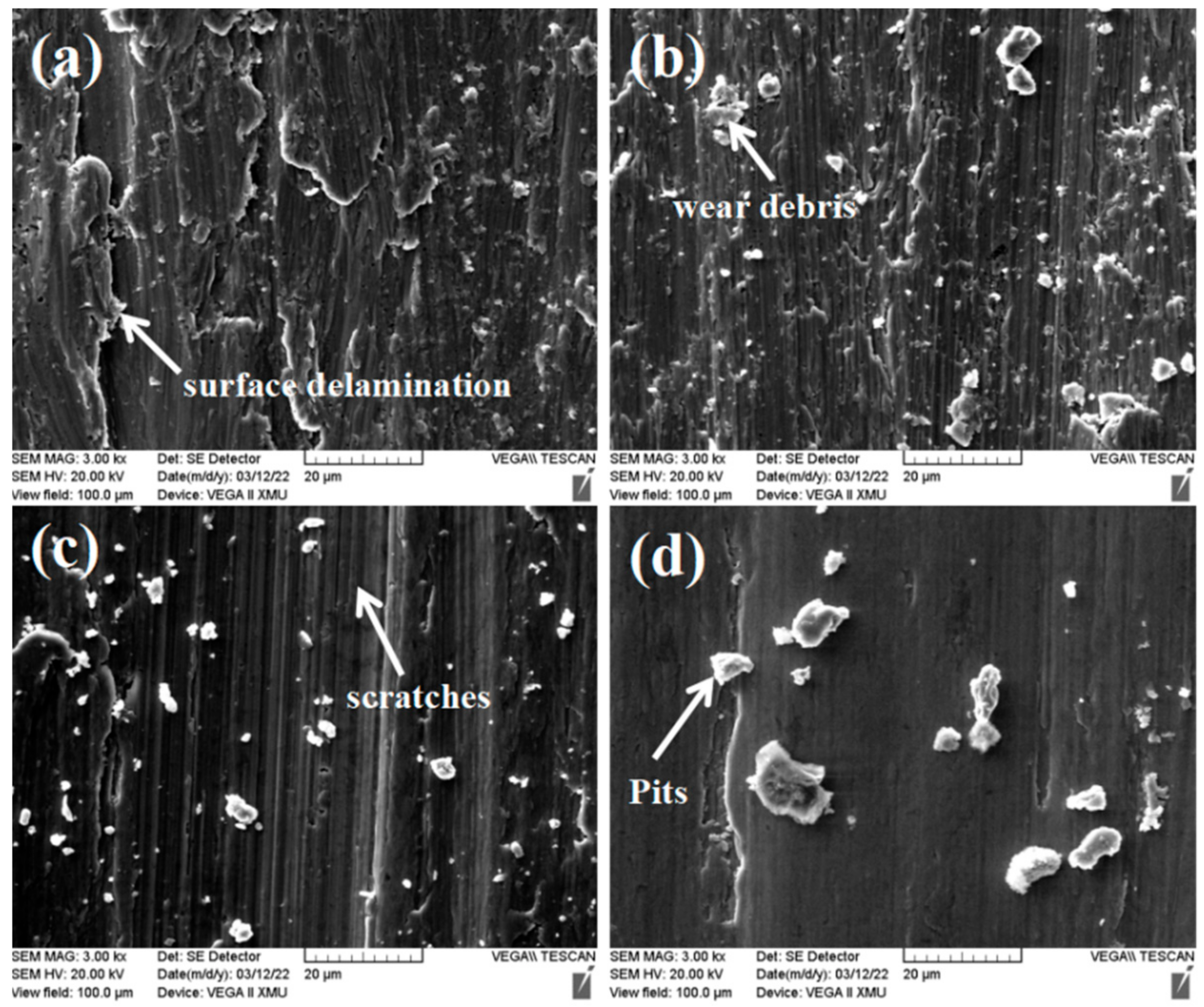
3.2. Mechanical Properties of the CoCrFeNiCu(SiC)x High-Entropy Alloy Coatings

Figure 4 shows the hardness as a function of the depth of the 316L stainless steels with CoCrFeNiCu(SiC)x HEA coatings. As can be seen, the hardness of the coatings with different SiC contents are all higher than that of the substrate. The values of the Vickers microhardness is obtained on the cross-section of the CoCrFeNiCu(SiC)x HEA coatings. The corresponding average hardness is 275.6, 384.3, 468.1, and 563.4 HV of CoCrFeNiCu, CoCrFeNiCu(SiC)5, CoCrFeNiCu(SiC)10, and CoCrFeNiCu(SiC)15 HEA coatings. The hardness of substrate is only 186 HV, which is about 1/3 of the CoCrFeNiCu(SiC)15 HEA coating. For CoCrFeNiCu HEA coating, there is no SiC and the hardness increased due to the property of CoCrFeNiCu high-entropy alloys. Usually, the HEAs are composed of 5 or more 5 elements, the atomic radius of each principal element is different and randomly occupies the point of crystal lattice, leading to obvious solid solution strengthening effects. The dislocation movement and grain boundary sliding will become difficult. Hence, the hardness of CoCrFeNiCu HEA coating increased [28]. When adding SiC ceramic particles in the CoCrFeNiCu HEA, the particle strengthening effect is also introduced. The SiC particles pin on the dislocations and grain boundaries to prevent plastic deformation and grain growth, resulting in the hardness increasing [29]. Especially for this work, a part of SiC has decomposed into Si and C during the laser cladding process, with a new compound of Cr7C3 formed. The Cr7C3 is a reinforcing phase precipitate at the grain boundaries (Figure 3), which also increased the hardness of the coatings. In addition, the rapid chilling in the laser cladding process is equivalent to quenching, which can enable the production of fine grains and grains with internal substructures, thereby improving the surface hardness [30].
Figure 5 shows the wear loss and friction coefficients of the four CoCrFeNiCu(SiC)x HEA coatings. With the increase of SiC content, Figure 5a shows that the wear weight of the coating gradually decreases from 1.6mg to 0.9mg, and Figure 5b shows the friction coefficient of the coating also decreases from 0.58 to 0.35. The decrease in wear weight and friction coefficient indicates that SiC will improve the wear resistance of the coating. According to Archard’s law [31], the friction coefficient and hardness of wear-resistant materials are inversely proportional. The hardness of the CoCrFeNiCu HEA coatings with SiC particles is much higher than that of the ones without SiC particles, leading to the friction coefficient of the coatings with SiC particles being bigger than that of the ones without SiC particles. The Cr7C3 phase, which precipitates at the grain boundaries, also influences the friction coefficient of the coatings. It can not only increase the resistance of the dislocation movement but also inhibit the plastic deformation of the HEA coatings.
Figure 6 shows the friction and wear morphology of the high-entropy alloy surface. The results show that many lamellar wear debris appear on the surface of the coating without SiC addition (Figure 6a), and fine scratches are formed. At the same time, there are many small holes in the wear scar furrow. After adding a certain content of SiC, the lamellar wear debris becomes less, but there are many granular wear debris. In Figure 6c,d, the wear debris particles are increasingly reduced. It is worth noting that the friction coefficient of the coating with the addition of SiC is getting smaller and smaller, indicating better wear resistance. It can also be seen in the wear scar morphology that with the addition of hard ceramic particles, the scratch wear is reduced, the furrows become shallower, and the surface of the wear scar becomes smoother and smoother. The wear forms of this coating are abrasive wear and adhesive wear.

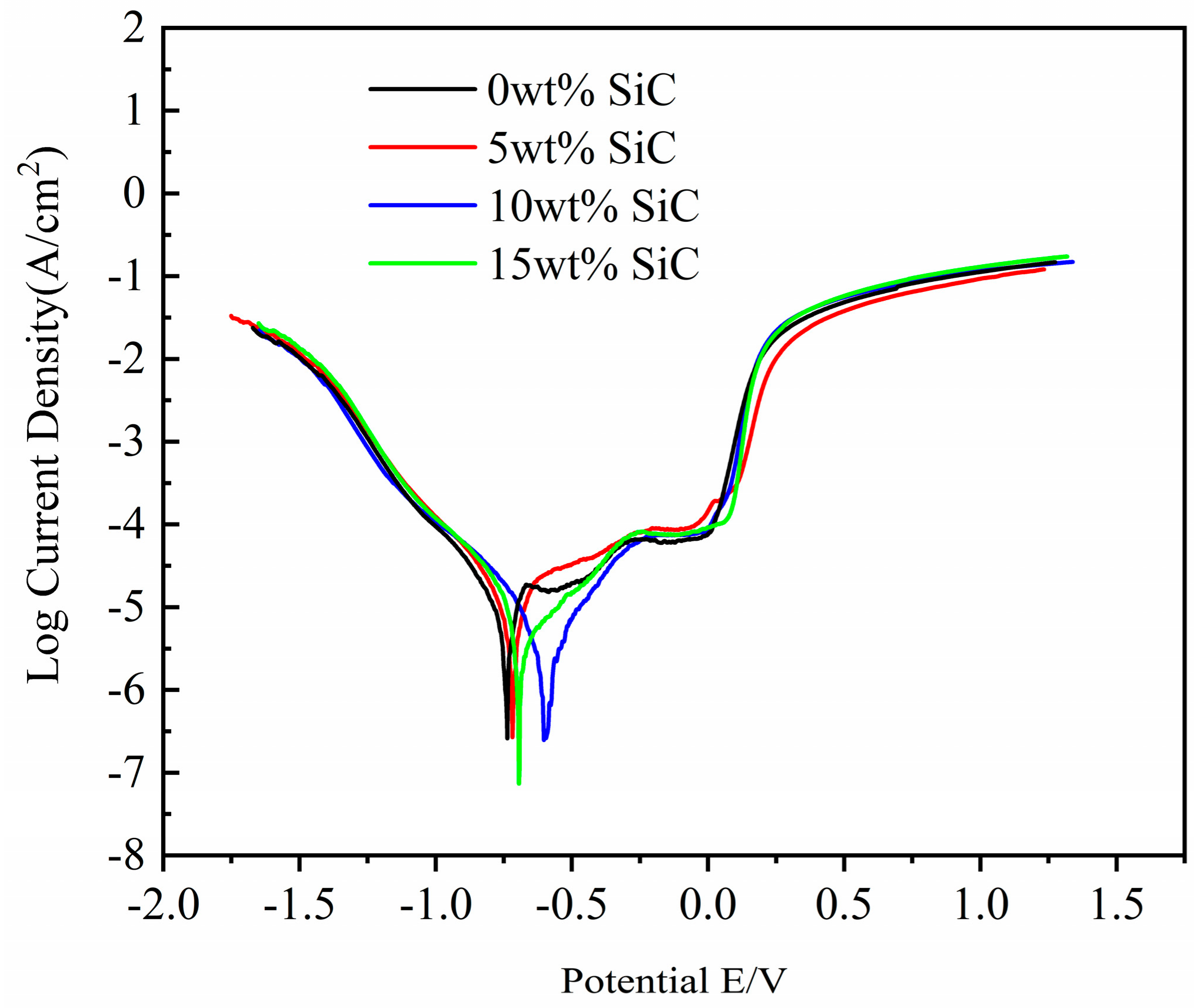
3.3. Electrochemical Properties of the CoCrFeNiCu(SiC)x High-Entropy Alloy Coatings

Electrochemical behavior of CoCrFeNiCu(SiC)x HEA coating was assessed using linear polarization in 3.5% NaCl solution at ambient temperatures. Figure 7 shows the linear polarization curves generated from measurements. As can be seen, all of the samples exhibit passive anodic regions (stable current at the potential ranging from −0.25 to 0 V), which indicates the formation of passive films on each coating surface during the process of electrochemical corrosion. Thus, electrolyte solutions can be used to retard WE surface corrosion. When SiC is added to the coating, the defects of the coating are reduced, and the corrosion resistance of the coating is improved. However, when the SiC content increased to 15 wt%, the peak of Cr7C3 in XRD was more obvious. It shows that the increase of Cr7C3 leads to the existence of chromium-depleted regions in the grains, the formation of potential difference with the grain boundaries, and the change of the properties of the passivation film. As a result, intergranular corrosion is stimulated, especially in chloride environments, resulting in a decrease in the corrosion resistance of the coating. Table 2 shows the electrochemical parameters of the four CoCrFeNiCu(SiC)x coatings after the polarization test. The free corrosion potential (Ecorr) and free corrosion density (Icorr) of the CoCrFeNiCu(SiC)x coatings both show a degree of regularity. According to electrochemical theory, Ecorr follows the thermodynamic trend of the corrosion of the WE, while Icorr corresponds to the dissolution of the WE. Both Ecorr and Icorr can be calculated via Tafel extrapolation based on the degree of linearity in the polarization curve. The optimal corrosion resistance occurs when the lowest corrosion current density is seen for the highest potential [32,33]. The observed trends in Ecorr and Icorr point to the superior corrosion resistance of the SiC-modified HEA compared with the unmodified HEA. Comparing the corrosion resistance of four CoCrFeNiCu(SiC)x coatings, with the increase of SiC content, Icorr and corrosion rate first decreased and then increased. It shows that adding SiC in a certain range can improve the corrosion resistance of CoCrFeNiCu(SiC)x HEA coating. However, with the increase of SiC content, the corrosion resistance of the coating decreases. The Icorr of CoCrFeNiCu and CoCrFeNiCu(SiC)5 coatings are both in the order of 10−2, while the Icorr of the CoCrFeNiCu(SiC)10 coating is reduced to the order of 10−3, and the Icorr of the CoCrFeNiCu(SiC)15 coating is increased to the order of 10−2. It shows that when the SiC content reaches 10 wt%, the corrosion resistance of CoCrFeNiCu(SiC)x HEA coating is significantly improved.

4. Conclusions

The CoCrFeNiCu(SiC)x HEA coatings have successfully been prepared on 316 L stainless steel via laser cladding technique. The as-prepared HEA coatings possess a simple FCC structure. With the contents of SiC increasing, the pores on the surface of the coatings are reduced. The HEA components are distributed uniformly on the surface of the coatings, except the enrichment of Cr and C at the grain boundaries. During the laser cladding process, the Cr7C3 is formed and precipitated at the dislocation and grain boundaries to increase the hardness of the coatings. However, in electrochemical corrosion, Cr7C3 easily causes intergranular corrosion. When the SiC content reaches 15 wt%, the highest hardness of the coating reaches 563.4 HV, which is about two times that of the CoCrFeNiCu HEA coatings. The HEA coating with SiC added shows better corrosion resistance. Among them, CoCrFeNiCu(SiC)10 has the highest self-corrosion potential, the smallest corrosion current, and the best corrosion resistance. These results demonstrate that CoCrFeNiCu(SiC)x HEA coatings could be used as a wear and corrosion barrier for 316L stainless steel.

Author Contributions

Conceptualization and funding acquisition, H.D.; writing and original draft preparation, L.X.; methodology and investigation, L.X. and J.L.; data curation and validation D.F. and S.X.; review and editing, J.L.; project administration, H.D. All authors have read and agreed to the published version of the manuscript.

Funding

This work was supported by the National Natural Science Foundation of China (Grant No. 52172099); and the Provincial Joint Fund of Shaanxi (Grant No. 2021JLM-28).

Institutional Review Board Statement

Not applicable.

Informed Consent Statement

Not applicable.

Data Availability Statement

The data presented in this study are available on request from the corresponding author.

Acknowledgments

Special thanks to Eryong Liu teacher for experimental assistance.

Conflicts of Interest

The authors declare no conflict of interest.

References

  1. Yeh, J.-W.; Chen, S.-K.; Lin, S.-J.; Gan, J.-Y.; Chin, T.-S.; Shun, T.-T.; Tsau, C.-H.; Chang, S.-Y. Nanostructured high-entropy alloys with multiple principal elements: Nanoslruetured high-entropy alloys novel alloy design eoneepls and outcomes. Adv. Eng. Mater. 2004, 6, 299–303. [Google Scholar] [CrossRef]
  2. Cai, Y.; Ao, S.; Manladan, S.M.; Xue, J.; Luo, Z. Evolution mechanisms of TiC ceramic particles in FeCoCrNiAl high-entropy alloy laser cladding layers. Mater. Res. Express 2019, 6, 1065d2. [Google Scholar] [CrossRef]
  3. Cai, Y.; Zhu, L.; Cui, Y.; Geng, K.; Manladan, S.M.; Luo, Z. High-temperature oxidation behavior of FeCoCrNiAlx high-entropy alloy coatings. Mater. Res. Express 2019, 6, 126552. [Google Scholar] [CrossRef]
  4. Tong, C.-J.; Chen, M.-R.; Yeh, J.-W.; Lin, S.-J.; Chen, S.-K.; Shun, T.-T.; Chang, S.-Y. Mechanical performance of the AlxCoCrCuFeNi high-entropy alloy system with multiprincipal elements. Metall. Mater. Trans. A 2005, 36, 1263–1271. [Google Scholar] [CrossRef]
  5. Hsu, C.-Y.; Juan, C.-C.; Wang, W.-R.; Sheu, T.-S.; Yeh, J.-W.; Chen, S.-K. On the superior hot hardness and softening resistance of AlCoCrxFeMo0.5Ni high-entropy alloys. Mater. Sci. Eng. A 2011, 528, 3581–3588. [Google Scholar] [CrossRef]
  6. Shu, F.Y.; Liu, S.; Zhao, H.Y.; He, W.X.; Sui, S.H.; Zhang, J.; He, P.; Xu, B.S. Structure and high-temperature property of amorphous composite coating synthesized by laser cladding FeCrCoNiSiB high-entropy alloy powder. J. Alloys Compd. 2018, 731, 662–666. [Google Scholar] [CrossRef]
  7. Chuang, M.-H.; Tsai, M.-H.; Wang, W.-R.; Lin, S.-J.; Yeh, J.-W. Microstructure and wear behavior of AlxCo1.5CrFeNi1.5Tiy high-entropy alloys. Acta Mater. 2011, 59, 6308–6317. [Google Scholar] [CrossRef]
  8. Jiang, X.J.; Wang, S.Z.; Fu, H.; Chen, G.Y.; Ran, Q.X.; Wang, S.Q.; Han, R.H. A novel high-entropy alloy coating on Ti-6Al-4V substrate by laser cladding. Mater. Lett. 2022, 308, 131131. [Google Scholar] [CrossRef]
  9. Abhijith, N.V.; Kumar, D.; Kalyansundaram, D. Development of Single-Stage TiNbMoMnFe High-Entropy Alloy Coating on 304L Stainless Steel Using HVOF Thermal Spray. J. Therm. Spray Technol. 2022. [Google Scholar] [CrossRef]
  10. Zhang, J.; Jia, T.; Zhu, H.; Xie, Z. Microstructure and mechanical properties of in-situ TiC reinforced FeCoNiCu2.0 high entropy alloy matrix composites. Mater. Sci. Eng. A 2021, 822, 141671. [Google Scholar] [CrossRef]
  11. Bao, Y.; Guo, L.; Zhong, C.; Song, Q.; Yang, K.; Jiang, Y.; Wang, Z.; Wang, Z.R. Effects of WC on the cavitation erosion resistance of FeCoCrNiB0.2 high entropy alloy coating prepared by laser cladding. Mater. Today Commun. 2021, 26, 102154. [Google Scholar] [CrossRef]
  12. Zhang, B.; Yu, Y.; Zhu, S.; Zhang, Z.; Tao, X.; Wang, Z.; Lu, B. Microstructure and wear properties of TiN-Al2O3-Cr2B multiphase ceramics in-situ reinforced CoCrFeMnNi high-entropy alloy coating. Mater. Chem. Phys. 2022, 276, 125352. [Google Scholar] [CrossRef]
  13. Qu, Y.; Qi, H.; Li, G.; Zhang, Y.; Tian, C.; Nie, S.; Tan, B.; Li, R.; Yu, B. The effect of nanometer phase SiC addition on the microstructure and mechanical properties of Al0.6CrFe2Ni2 high entropy alloys. Mater. Technol. 2021, 1, 1–7. [Google Scholar] [CrossRef]
  14. Szklarz, Z.; Lekki, J.; Bobrowski, P.; Szklarz, M.B.; Rogal, Ł. The effect of SiC nanoparticles addition on the electrochemical response of mechanically alloyed CoCrFeMnNi high entropy alloy. Mater. Chem. Phys. 2018, 215, 385–392. [Google Scholar] [CrossRef]
  15. Khan, N.A.; Akhavan, B.; Zheng, Z.; Liu, H.; Zhou, C.; Zhou, H.; Chang, L.; Wang, Y.; Liu, Y.; Sun, L.; et al. Nanostructured AlCoCrCu0.5FeNi high entropy oxide (HEO) thin films fabricated using reactive magnetron sputtering. Appl. Surf. Sci. 2021, 553, 149491. [Google Scholar] [CrossRef]
  16. Böőr, K.; Qiu, R.; Forslund, A.; Bäcke, O.; Larsson, H.; Lindahl, E.; Halvarsson, M.; Boman, M.; von Fieandt, L. Chemical vapor deposition of TiN on a CoCrFeNi multi-principal element alloy substrate. Surf. Coat. Technol. 2020, 393, 125778. [Google Scholar] [CrossRef]
  17. Xiao, J.-K.; Tan, H.; Wu, Y.-Q.; Chen, J.; Zhang, C. Microstructure and wear behavior of FeCoNiCrMn high entropy alloy coating deposited by plasma spraying. Surf. Coat. Technol. 2020, 385, 125430. [Google Scholar] [CrossRef]
  18. Tian, Y.; Chen, C.; Chen, L.; Huo, Q. Effect of RE oxides on the microstructure of the coatings fabricated on titanium alloys by laser alloying technique. Scr. Mater. 2006, 54, 847–852. [Google Scholar] [CrossRef]
  19. Calleja, A.; Urbikain, G.; González, H.; Cerrillo, I.; Polvorosa, R.; Lamikiz, A. Inconel® 718 superalloy machinability evaluation after laser cladding additive manufacturing process. Int. J. Adv. Manuf. Technol. 2018, 97, 2873–2885. [Google Scholar] [CrossRef]
  20. Lampa, C.; Smirnov, I. High speed laser cladding of an iron based alloy developed for hard chrome replacement. J. Laser Appl. 2019, 31, 022511. [Google Scholar] [CrossRef]
  21. Liu, X.; Zhang, P.; Yan, H.; Lu, Y.; Yu, Z.; Li, C.; Lu, Q.; Qiu, D. Microstructure and wear properties of Ni-W-Si coatings by laser cladding. Appl. Mech. Mater. 2015, 750, 214–219. [Google Scholar] [CrossRef]
  22. Nair, A.M.; Muvvala, G.; Nath, A.K. A study on in-situ synthesis of TiCN metal matrix composite coating on Ti–6Al–4V by laser surface alloying process. J. Alloys Compd. 2019, 810, 151901. [Google Scholar] [CrossRef]
  23. Li, Y.; Dong, S.; Liu, X.; He, P.; Ren, X.; Yan, S.; Xu, B. Interface phase evolution during laser cladding of Ni-Cu alloy on nodular cast iron by powder pre-placed method. Opt. Laser. Technol. 2021, 135, 106684. [Google Scholar] [CrossRef]
  24. Sun, Z.; Li, X.; Wang, Z. Microstructure and mechanical properties of low activation Fe-Ti-Cr-V-W multi-principal element alloys. J. Nucl. Mater. 2020, 533, 152078. [Google Scholar] [CrossRef]
  25. Pan, Y.; Baptista, J.L. Chemical instability of silicon carbide in the presence of transition metals. J. Am. Ceram. Soc. 1996, 79, 2017–2026. [Google Scholar] [CrossRef]
  26. Zhang, H.; He, Y.-Z.; Pan, Y.; Guo, S. Thermally stable laser cladded CoCrCuFeNi high-entropy alloy coating with low stacking fault energy. J. Alloys Compd. 2014, 600, 210–214. [Google Scholar] [CrossRef]
  27. Anthonysamy, S.; Ananthasivan, K.; Kaliappan, I.; Chandramouli, V.; Rao, P.R.V.; Mathews, C.K.; Jacob, K.T. Gibbs energies of formation of chromium carbides. Metall. Mater. Trans. A 1996, 27, 1919–1924. [Google Scholar] [CrossRef]
  28. Aguilar-Hurtado, J.Y.; Vargas-Uscategui, A.; Paredes-Gil, K.; Palma-Hillerns, R.; Tobar, M.J.; Amado, J.M. Boron addition in a non-equiatomic Fe50Mn30Co10Cr10 alloy manufactured by laser cladding: Microstructure and wear abrasive resistance. Appl. Surf. Sci. 2020, 515, 146084. [Google Scholar] [CrossRef]
  29. Chen, K.; Wang, T.; Wang, X.; Jiang, Y.; Xue, J.; Liu, X.; Jiang, Y.; Chen, Z. Effect of Submicron SiC Particles on the Properties of Alcocrfeni High Entropy Alloy Coatings. Powder Metall. Met. Ceram. 2020, 59, 424–433. [Google Scholar] [CrossRef]
  30. Lu, J.; Lu, H.; Xu, X.; Yao, J.; Cai, J.; Luo, K. High-performance integrated additive manufacturing with laser shock peening-induced microstructural evolution and improvement in mechanical properties of Ti6Al4V alloy components. Int. J. Mach. Tools Manuf. 2020, 148, 103475. [Google Scholar] [CrossRef]
  31. Achard, J.F. Contact and rubbing of flat surface. J. Appl. Phys. 1953, 24, 981–988. [Google Scholar] [CrossRef]
  32. Qiu, X.-W.; Liu, C.-G. Microstructure and properties ofAl2CrFeCoCuTiNix high-entropy alloys prepared by laser cladding. J. Alloys Compd. 2013, 553, 216–220. [Google Scholar] [CrossRef]
  33. Qui, Y.; Thomas, S.; Fabajanic, D.; Barlow, A.J.; Fraser, H.L.; Birbilis, N. Microstructural evolution, electrochemical and corrosion properties of AlxCoCrFeNiTiy high entropy alloys. Mater. Des. 2019, 170, 107698. [Google Scholar] [CrossRef]
Figure 1. (a) XRD pattern of CoCrFeNiCu(SiC)x HEA coatings, (b) enlarged XRD (200) peak of CoCrFeNiCu(SiC)x HEA coatings.
Coatings 12 00519 g001
Figure 2. SEM micrographs of CoCrFeNiCu(SiC)x HEA coatings: (a) 0 wt% SiC, (b) 5 wt% SiC, (c) 10 wt% SiC, and (d) 15 wt% SiC.
Coatings 12 00519 g002
Figure 3. Mapping images of the CoCrFeNiCu(SiC)10 HEA coating.
Coatings 12 00519 g003
Figure 4. Microhardness distributions along the depth direction in the cross-section of the CoCrFeNiCu(SiC)x HEA coatings.
Coatings 12 00519 g004
Figure 5. (a) Wear loss of CoCrFeNiCu(SiC)x HEA coatings, (b) Friction coefficient of CoCrFeNiCu(SiC)x HEA coatings.
Coatings 12 00519 g005
Figure 6. Surface wear scar SEM morphologies of CoCrFeNiCu(SiC)x HEA coatings: (a) 0 wt% SiC, (b) 5 wt% SiC, (c) 10 wt% SiC, and (d) 15 wt% SiC.
Coatings 12 00519 g006
Figure 7. Shows the polarization curves of the CoCrFeNiCu(SiC)x HEA coatings after the polarization test in 3.5% NaCl solution.
Coatings 12 00519 g007
Table 1. Laser parameters for laser surface alloying of CoCrFeNiCu(SiC)x HEA coatings.
Beam Diameter
(mm)
Defocus Distance
(mm)
Power (w)Scanning Speed
(mm/min)
2 × 1520.42000180
Table 2. The corrosion parameters of the four CoCrFeNiCu(SiC)x HEA coatings.
SamplesBa (mv)Bc (mv)Ecorr (mv)Icorr (mA/cm2)Corrosion Rate (mm/a)
0 wt% SiC781.2589.16−717.694.3094 × 10−20.080099
5 wt% SiC209.97168.15−707.343.7538 × 10−20.058383
10 wt% SiC471.6401.48−597.892.4136 × 10−30.040087
15 wt% SiC344.1266.69−693.971.5144 × 10−20.051372
Publisher’s Note: MDPI stays neutral with regard to jurisdictional claims in published maps and institutional affiliations.

