
Influence of Heat Treatment on the Microstructure and Wear Properties of Arc-Sprayed FeCrAl/Al Coating


Abstract
:1. Introduction
2. Materials and Methods
2.1. Coating Preparation
2.2. Microstructural Characterization
3. Results and Discussion
3.1. Coating Characterization
3.2. Tensile Bonding Strength

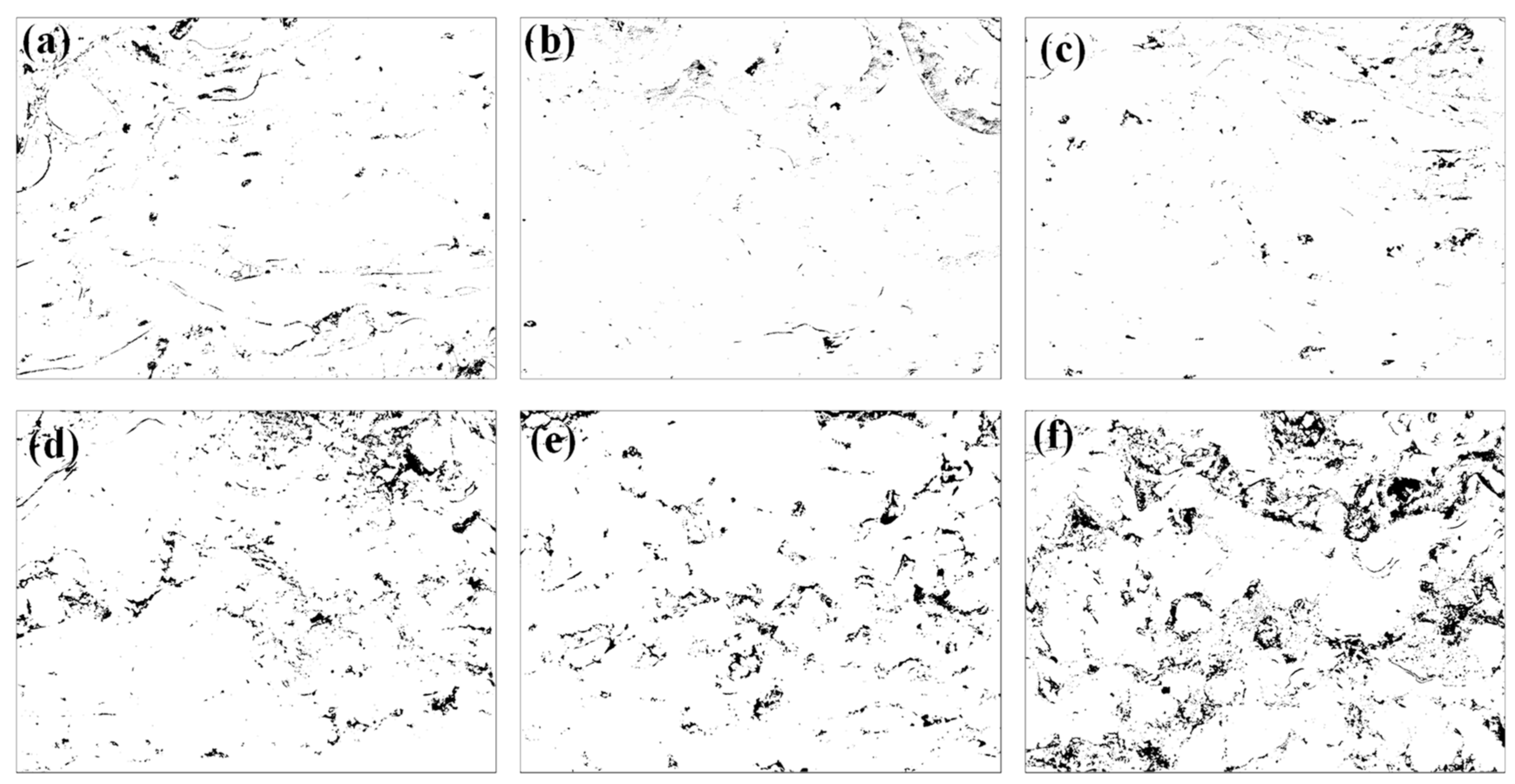
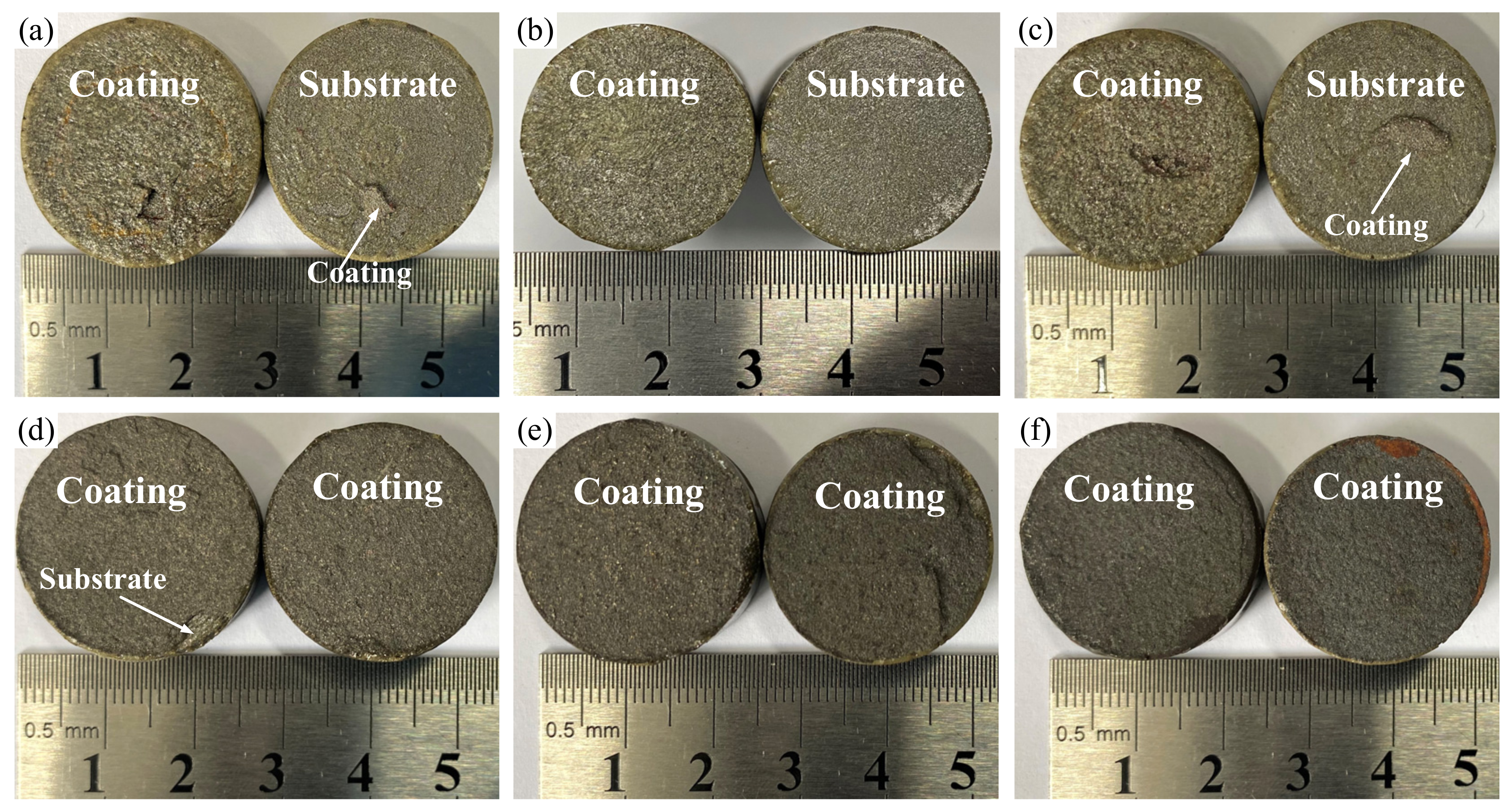
| Coating Temperature | Porosity (%) | Tensile Bonding Strength (MPa) | Type of Failure |
|---|---|---|---|
| As-sprayed | 3.6 | 30.0 | Adhesive failure |
| 300 °C | 3.0 | 37.5 | Adhesive failure |
| 400 °C | 3.4 | 33.1 | Adhesive failure |
| 500 °C | 4.1 | 24.0 | Cohesive failure |
| 600 °C | 5.8 | 20.6 | Cohesive failure |
| 700 °C | 8.1 | 20.2 | Cohesive failure |
3.3. XRD Analysis
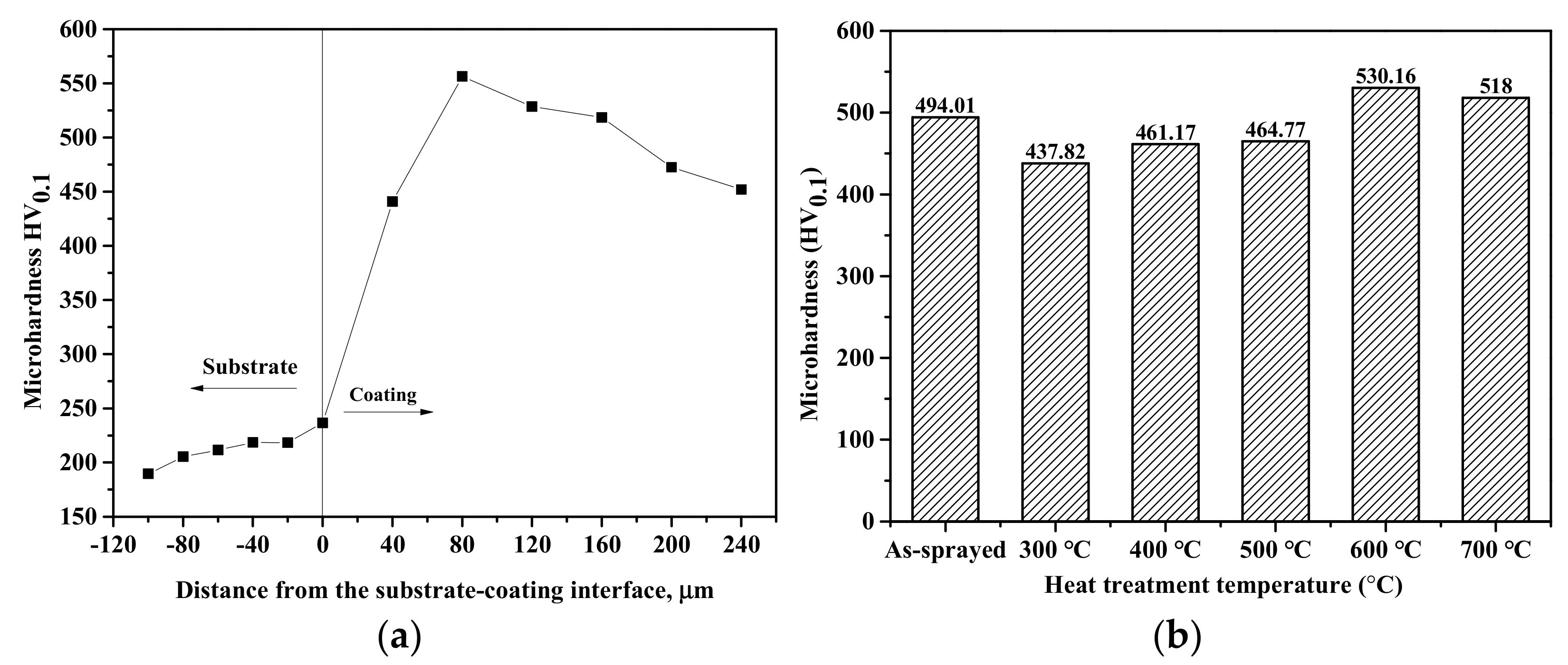
3.4. Microhardness
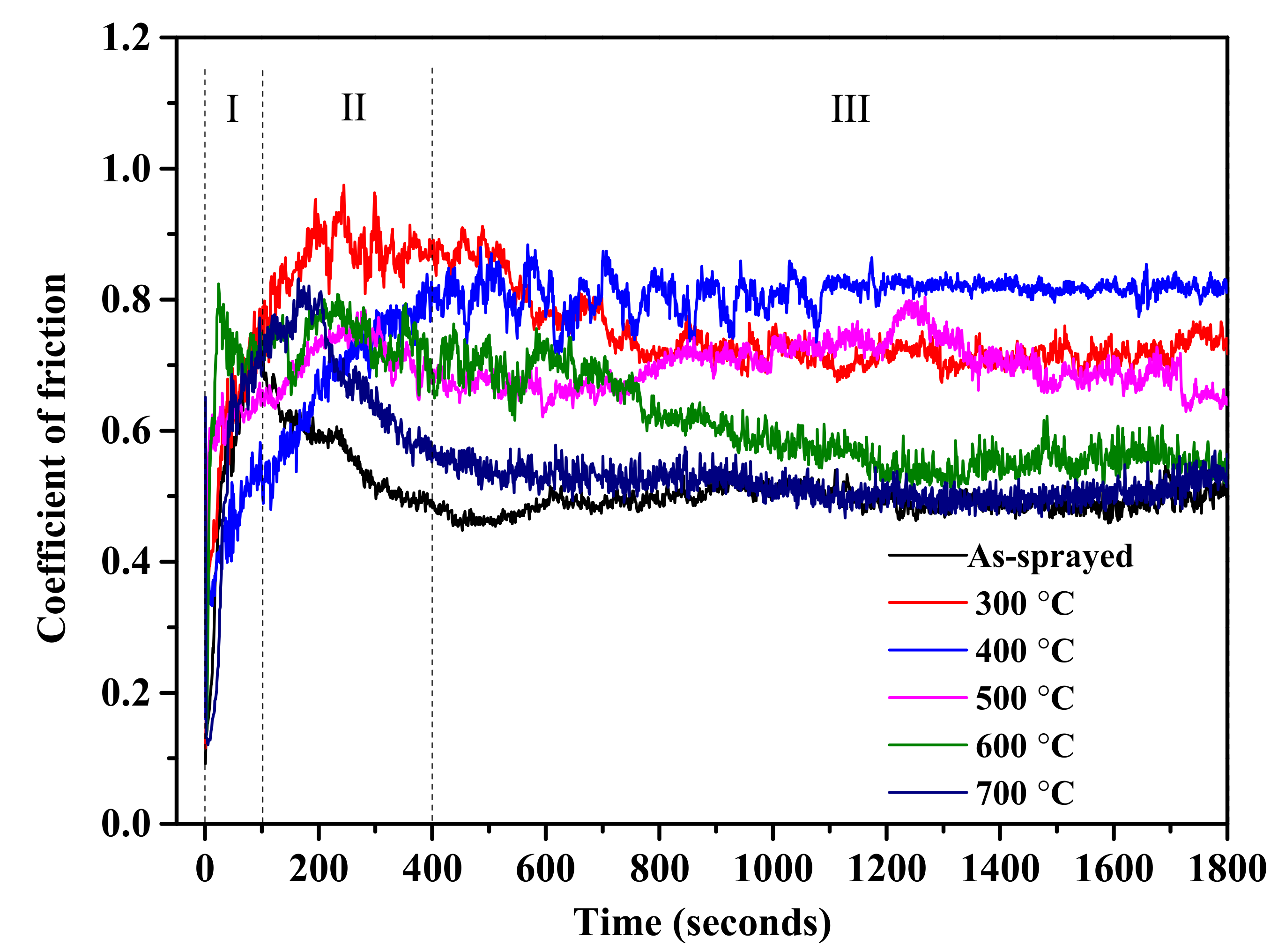
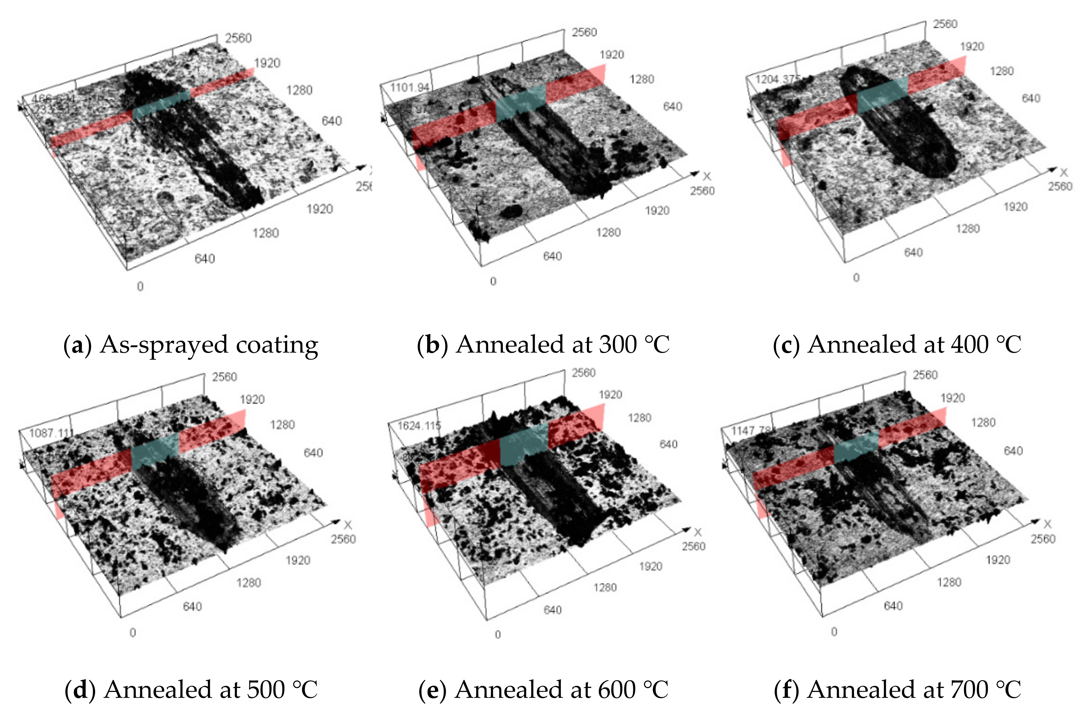
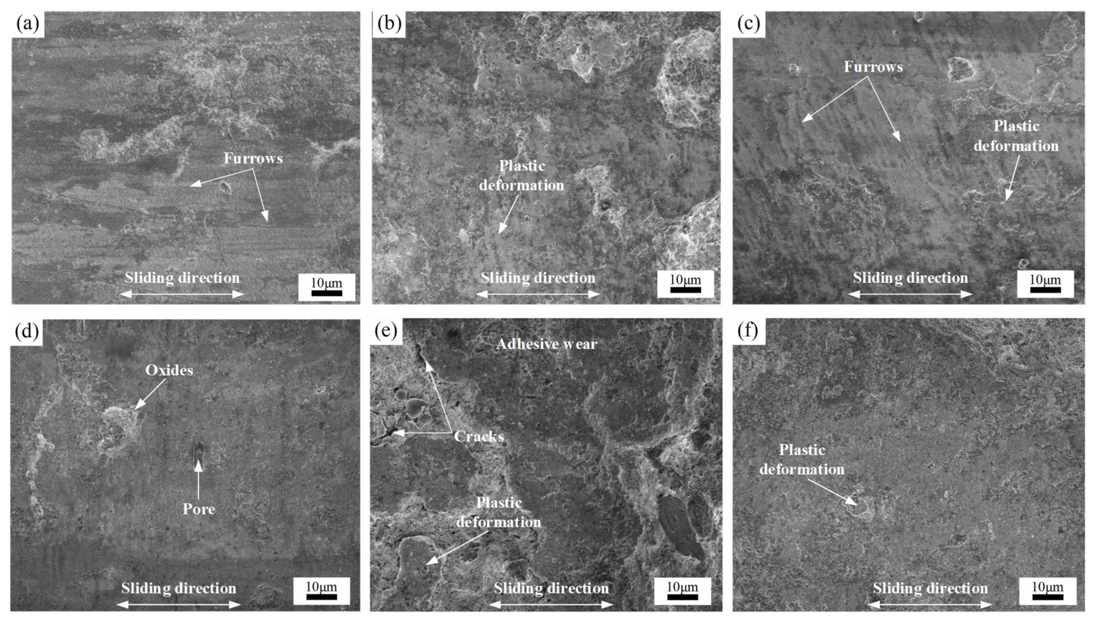
3.5. Wear Behavior
4. Conclusions
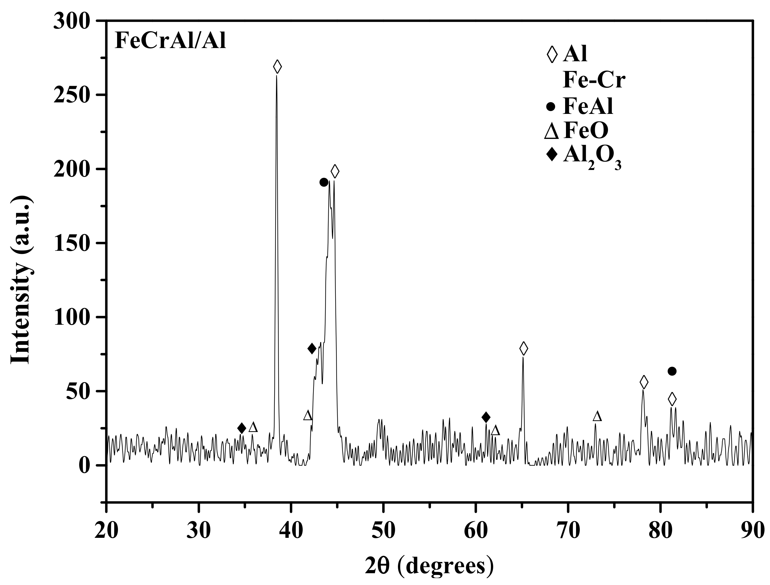
- FeCrAl/Al composite coating was prepared by arc spraying FeCrAl and Al wires as the anode and cathode, respectively. The coatings had a layered structure comprised of oxides, some pores, and alternating splats of FeCrAl and Al.
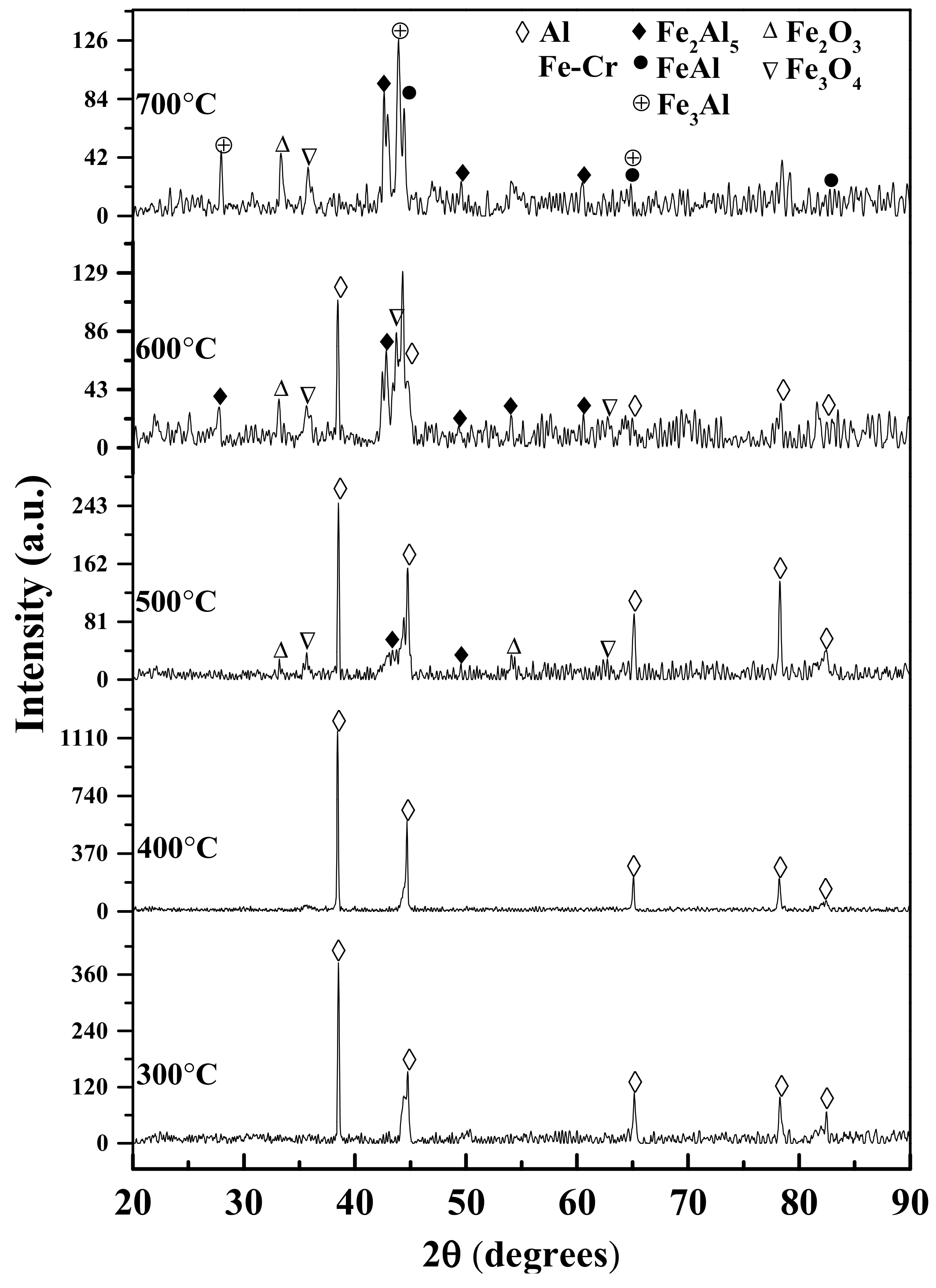
- FeCr and Al were the main phases of the as-sprayed coating. The FeAl intermetallic phases (Fe2Al5, Fe3Al, FeAl) were formed at 500 °C and increased with increasing heat treatment temperatures from 500 to 700 °C.
- The as-sprayed coating had a microhardness of 494.01 HV0.1, which was 2.3 times that of the substrate, while the microhardness of the annealed coatings slightly increased with increasing heat treatment temperature. The hardness of the heat-treated coatings was influenced by the precipitation hardening effect of the iron oxides (Fe2O3 and Fe3O4) and the FeAl intermetallic compounds.
- The average wear rates of annealed coatings decreased with increasing temperature. The as-sprayed coating possessed the highest wear resistance compared with the annealed coatings. The formation of the hard and brittle FeAl intermetallic phases, coating microhardness, and microstructure influenced the wear resistance of the annealed coatings.
Author Contributions
Funding
Institutional Review Board Statement
Informed Consent Statement
Data Availability Statement
Conflicts of Interest
References
- Boronenkov, V.; Korobov, Y. Fundamentals of arc spraying. In Physical and Chemical Regularities; Springer: Berlin/Heidelberg, Germany, 2016. [Google Scholar]
- Lee, J.; Kwon, H.; Kim, Y.-G.; Lee, C. Tribological and Microstructural Properties of Carbon Steel Coatings Fabricated by Wire Arc Spray. Met. Mater. Int. 2019, 26, 650–659. [Google Scholar] [CrossRef]
- Samal, S. Thermal plasma technology: The prospective future in material processing. J. Clean. Prod. 2017, 142, 3131–3150. [Google Scholar] [CrossRef]
- Koiprasert, H.; Sheppard, P. FeAl and FeCrAl as Alternative Coatings for NiAl. Chiang Mai J. Sci. 2013, 40, 839–848. [Google Scholar]
- Ndumia, J.N.; Kang, M.; Gbenontin, B.V.; Lin, J.; Nyambura, S.M. A Review on the Wear, Corrosion and High-Temperature Resistant Properties of Wire Arc-Sprayed Fe-Based Coatings. Nanomaterials 2021, 11, 2527. [Google Scholar] [CrossRef] [PubMed]
- Deevi, S.C. Advanced intermetallic iron aluminide coatings for high temperature applications. Prog. Mater. Sci. 2021, 118, 100769. [Google Scholar] [CrossRef]
- Malek, M.H.A.; Saad, N.H.; Abas, S.K.; Roselina, N.N.; Shah, N.M. Performance and microstructure analysis of 99.5% aluminium coating by thermal arc spray technique. Procedia Eng. 2013, 68, 558–565. [Google Scholar] [CrossRef] [Green Version]
- Lee, H.-S.; Singh, J.K.; Park, J.H. Pore blocking characteristics of corrosion products formed on Aluminum coating produced by arc thermal metal spray process in 3.5 wt.% NaCl solution. Constr. Build. Mater. 2016, 113, 905–916. [Google Scholar] [CrossRef]
- Zhao, J.H.; Wang, L.; Shang, Z.H. Influence of FeCrAl Coating Arc Sprayed on Aluminum Corrosion Resistance of H13 Steel. In Materials Science Forum; Trans Tech Publications Ltd.: Freinbach, Switzerland, 2015. [Google Scholar]
- Chen, Y.-X.; Xu, B.-S.; Yan, L.; Liang, X.-B.; Yi, X. Structure and sliding wear behavior of 321 stainless steel/Al composite coating deposited by high velocity arc spraying technique. Trans. Nonferrous Met. Soc. China 2008, 18, 603–609. [Google Scholar] [CrossRef]
- Bratean, L. Thermal spraying arc process with two dissimilar wires–quality tests. In Proceedings of the 6th International Conference Edu World 2014 Education Facing Contemporary World Issues, Pitesti, Romania, 7–9 November 2014; Elsevier: Amsterdam, The Netherlands, 2015; pp. 1116–1121. [Google Scholar]
- Wichmanowski, S. Pseudo-alloys for spray metal tooling: Pseudo-alloys have enhanced the durability of metal-faced composite tooling for metal forming and plastics molding. Adv. Mater. Process. 2003, 161, 33–35. [Google Scholar]
- Bratean, L.; Miclosi, V.; Voiculescu, I.; Iacobescu, G. Research on anticorrosion characteristics of AlZn pseudo-alloy obtained by metal-arc process. UPB. Sci. Bull Ser. D 2011, 73, 151–163. [Google Scholar]
- Watanabe, T.; Sato, T.; Nezu, A. Electrode phenomena investigation of wire arc spraying for preparation of Ti-Al intermetallic compounds. Thin Solid Films. 2002, 407, 98–103. [Google Scholar] [CrossRef]
- Xu, R.; Song, G. Post-heat treatment of arc-sprayed coating prepared by the wires combination of Mg-cathode and Al-anode to form protective intermetallic layers. Appl. Surf. Sci. 2011, 257, 3097–3102. [Google Scholar] [CrossRef]
- Chen, Y.; Liang, X.; Wei, S.; Liu, Y.; Xu, B. Heat treatment induced intermetallic phase transition of arc-sprayed coating prepared by the wires combination of aluminum-cathode and steel-anode. Appl. Surf. Sci. 2009, 255, 8299–8304. [Google Scholar] [CrossRef]
- Zhou, J.; Yang, M.; Wang, R.; Pang, X. Annealing behavior of aluminum coating prepared by arc spraying on P355NL1 steel. Surf. Coat. Technol. 2017, 330, 53–60. [Google Scholar] [CrossRef]
- Ekrem, A.; Sedat, I.; Fatih, U. Wear-resistant intermetallic arc spray coatings. Mater. Technol. 2012, 46, 181–183. [Google Scholar]
- Ndiithi, N.J.; Kang, M.; Zhu, J.; Lin, J.; Nyambura, S.M.; Liu, Y.; Huang, F. Microstructural and corrosion behavior of high velocity arc sprayed FeCrAl/Al composite coating on Q235 steel substrate. Coatings 2019, 9, 542. [Google Scholar] [CrossRef] [Green Version]
- Liu, G.; Rożniatowski, K.; Kurzydłowski, K. Quantitative characteristics of FeCrAl films deposited by arc and high-velocity arc spraying. Mater. Charact. 2001, 46, 99–104. [Google Scholar] [CrossRef]
- Kobayashi, S.; Yakou, T. Control of intermetallic compound layers at interface between steel and aluminum by diffusion-treatment. Mater. Sci. Eng. 2002, 338, 44–53. [Google Scholar] [CrossRef]
- ASTM C633-13; Standard Test Method for Adhesion or Cohesion Strength of Thermal Spray Coatings. ASTM International: West Conshohocken, PA, USA, 2017. [CrossRef]
- ASTM G133-05; Standard Test Method for Linearly Reciprocating Ball-on-Flat Sliding Wear. ASTM International: West Conshohocken, PA, USA, 2010. [CrossRef]
- Newbery, A.; Grant, P. Oxidation during electric arc spray forming of steel. J. Mater. Process. Technol. 2006, 178, 259–269. [Google Scholar] [CrossRef]
- Li, Z.-R.; Li, D.-Y.; Zhang, N.-N.; Huang, H.; Wang, X. Wear mechanism of iron-based alloy coating by arc spraying. J. Iron Steel Res. Int. 2016, 23, 834–841. [Google Scholar] [CrossRef]
- Samal, S. Study of Porosity on Titania Slag Obtained by Conventional Sintering and Thermal Plasma Process. J. Mater. 2016, 68, 3000–3005. [Google Scholar] [CrossRef]
- Wang, H.-T.; Li, C.-J.; Ji, G.-C.; Yang, G.-J. Annealing effect on the intermetallic compound formation of cold sprayed Fe/Al composite coating. J. Therm. Spray Technol. 2012, 21, 571–577. [Google Scholar] [CrossRef]
- Kang, Y.; Chen, Y.; Yan, C.; Kong, L. Influences of Structural Relaxation and Crystallization on Dry-Sliding Tribological Behavior of Fe-Based Amorphous Coating. Tribol. Lett. 2021, 69, 63. [Google Scholar] [CrossRef]
- Zhou, L.; Luo, F.; Zhou, W.; Zhu, D. Influence of FeCrAl content on microstructure and bonding strength of plasma-sprayed FeCrAl/Al2O3 coatings. J. Therm. Spray Technol. 2016, 25, 509–517. [Google Scholar] [CrossRef]
- Vencl, A.; Arostegui, S.; Favaro, G.; Zivic, F.; Mrdak, M.; Mitrović, S.; Popovic, V. Evaluation of adhesion/cohesion bond strength of the thick plasma spray coatings by scratch testing on coatings cross-sections. Tribol. Int. 2011, 44, 1281–1288. [Google Scholar] [CrossRef]
- Komaki, M.; Mimura, T.; Kurahasi, R.; Odahara, H.; Amiya, K.; Saotome, Y.; Yamasaki, T. Influence of Substrate Temperature on Structure and Adhesion Strength of Fe–Cr–P–C Amorphous Coating Films Produced by Thermal Spraying Technique. Mater. Trans. 2012, 53, 681–689. [Google Scholar] [CrossRef] [Green Version]
- Komaki, M.; Mimura, T.; Tsuji, S.; Amiya, K.; Saotome, Y.; Yamasaki, T. Influence of Substrate Temperature on the Structure and Cohesive/Adhesive Strength of Fe-Co-Si-B-Nb Metallic Glass Coating Films Produced by Thermal Spraying. Mater. Trans. 2012, 53, 2151–2159. [Google Scholar] [CrossRef] [Green Version]
- Peng, Y.; Zhang, C.; Zhou, H.; Liu, L. On the bonding strength in thermally sprayed Fe-based amorphous coatings. Surf. Coat. Technol. 2013, 218, 17–22. [Google Scholar] [CrossRef]
- Luo, L.-M.; Liu, S.-G.; Jia, Y.; Juan, L.; Jian, L. Effect of Al content on high temperature erosion properties of arc-sprayed FeMnCrAl/Cr3C2 coatings. Trans. Nonferrous Met. Soc. China 2010, 20, 201–206. [Google Scholar] [CrossRef]
- Tailor, S.; Vashishtha, N.; Modi, A.; Modi, S. Oxidation control in arc-sprayed SS420 coating. Surf. Eng. 2021, 37, 581–589. [Google Scholar] [CrossRef]
- Neiser, R.; Smith, M.; Dykhuizen, R. Oxidation in wire HVOF-sprayed steel. J. Therm. Spray Technol. 1998, 7, 537–545. [Google Scholar] [CrossRef]
- Wang, H.-T.; Li, C.-J.; Yang, G.-J.; Li, C.-X. Cold spraying of Fe/Al powder mixture: Coating characteristics and influence of heat treatment on the phase structure. Appl. Surf. Sci. 2008, 255, 2538–2544. [Google Scholar] [CrossRef]
- Gialanella, S.; Amils, X.; Baro, M.; Delcroix, P.; le Caër, G.; Lutterotti, L.; Suriñach, S. Microstructural and kinetic aspects of the transformations induced in a FeAl alloy by ball-milling and thermal treatments. Acta Mater. 1998, 46, 3305–3316. [Google Scholar] [CrossRef]
- Wang, H.-T.; Li, C.-J.; Yang, G.-J.; Li, C.-X. Effect of heat treatment on the microstructure and property of cold-sprayed nanostructured FeAl/Al2O3 intermetallic composite coating. Vacuum 2008, 83, 146–152. [Google Scholar] [CrossRef]
- Mukhopadhyay, A.; Barman, T.K.; Sahoo, P. Effects of heat treatment on tribological behavior of electroless Ni–B coating at elevated temperatures. Surf. Rev. Lett. 2017, 24, 1850014. [Google Scholar] [CrossRef]
- Han, Y.; Li, L. Erosion-Wear Behavior and Mechanism of HVAS Coatings. In Advanced Tribology; Springer: Berlin/Heidelberg, Germany, 2009; pp. 801–803. [Google Scholar]
- Tian, H.; Wang, C.; Guo, M.; Tang, Z.; Wei, S.; Xu, B. Frictional wear performance under oil-lubricated conditions and wear resistance mechanism of high-velocity arc-sprayed FeNiCrAl coating. Surf. Coat. Technol. 2018, 353, 237–246. [Google Scholar] [CrossRef]
- Tariq, N.; Hasan, B.; Akhter, J.; Ali, F. Mechanical and tribological properties of Zr-Al-Ni-Cu bulk metallic glasses. J. Alloys Compd. 2009, 469, 179–185. [Google Scholar] [CrossRef]
- Tian, H.; Wei, S.; Chen, Y.; Tong, H.; Liu, Y.; Xu, B. Adhesive strength and abrasive property of Fe based composite coating deposited by high velocity arc spraying. Mater. Res. Innov. 2014, 18, S2-363–S2-367. [Google Scholar] [CrossRef]
- Gao, M.; Lu, W.; Yang, B.; Zhang, S.; Wang, J. High corrosion and wear resistance of Al-based amorphous metallic coating synthesized by HVAF spraying. J. Alloys Compd. 2018, 735, 1363–1373. [Google Scholar] [CrossRef]
- Chen, Y.; Liang, X.; Bai, J.; Xu, B. High velocity electric arc sprayed Fe-Al-Nb-B composite coating and its wear behavior. Acta Met. Sin.-Engl. 2013, 26, 313–320. [Google Scholar] [CrossRef]
- Mozgovoy, S.; Hardell, J.; Prakash, B. High Temperature Friction and Wear Performance of PVD Coatings under Press Hardening Contact Conditions. Adv. Tribol. 2019, 2019, 4981246. [Google Scholar] [CrossRef] [Green Version]
- Mouadji, Y.; Bradai, M.A.; Younes, R.; Sad-eddine, A.; Benabbas, A. Influence of heat treatment on microstructure and tribological properties of flame spraying Fe-Ni-Al alloy coating. J. Cent South Univ. 2018, 25, 473–481. [Google Scholar] [CrossRef]
- Li, Q.; Song, P.; Ji, Q.; Huang, Y.; Li, D.; Zhai, R.; Zheng, B.; Lu, J. Microstructure and wear performance of arc-sprayed Al/316L stainless-steel composite coating. Surf. Coat. Technol. 2019, 374, 189–200. [Google Scholar] [CrossRef]
- Segu, D.Z.; Hwang, P.; Kim, S.-S. Effect of the temperature on the friction and wear properties of bulk amorphous alloy. Surf. Rev. Lett. 2014, 21, 1450067. [Google Scholar] [CrossRef]
- Zhu, W.; Kang, M.; Ndumia, J.N.; Lin, J.; Huang, F.; Zhang, Y. Microstructure and Wear Properties of TiB2 Reinforced Fe-Based Composite Coating. J. Mater. Eng. Perform. 2022, 1–12. [Google Scholar] [CrossRef]


| Coating | Region | Elements | |||
|---|---|---|---|---|---|
| Fe (at. %) | Cr (at. %) | Al (at. %) | O (at. %) | ||
| A | 71.13 | 12.57 | 11.64 | 4.66 | |
| As-sprayed | B | 1.28 | 0.38 | 94.14 | 4.20 |
| A | 61.58 | 17.23 | 13.57 | 7.62 | |
| 300 °C | B | 0.65 | 0.18 | 96.77 | 2.40 |
| A | 61.34 | 12.90 | 20.66 | 5.10 | |
| 400 °C | B | 1.12 | 0.22 | 97.02 | 1.64 |
| A | 58.75 | 22.02 | 8.12 | 11.11 | |
| 500 °C | B | 1.31 | 0.29 | 95.00 | 3.40 |
| C | 19.82 | 2.43 | 77.06 | 0.69 | |
| A | 69.29 | 14.10 | 10.56 | 6.05 | |
| 600 °C | B | 2.31 | 0.32 | 91.61 | 5.75 |
| C | 17.96 | 6.32 | 71.56 | 4.16 | |
| A | 76.88 | 11.73 | 7.70 | 3.69 | |
| 700 °C | B | 24.20 | 4.32 | 56.90 | 14.57 |
| C | 20.90 | 10.24 | 56.13 | 12.73 |
| Coating | As-Sprayed | 300 °C | 400 °C | 500 °C | 600 °C | 700 °C |
|---|---|---|---|---|---|---|
| Wear width (µm) | 480 | 702 | 695 | 657 | 575 | 498 |
| Wear rate (×10−6 mm3/N·m) | 24.03 | 85.78 | 78.9 | 66.90 | 51.00 | 34.68 |
Publisher’s Note: MDPI stays neutral with regard to jurisdictional claims in published maps and institutional affiliations. |
© 2022 by the authors. Licensee MDPI, Basel, Switzerland. This article is an open access article distributed under the terms and conditions of the Creative Commons Attribution (CC BY) license (https://creativecommons.org/licenses/by/4.0/).
Share and Cite
Ndumia, J.N.; Kang, M.; Lin, J.; Liu, J.; Li, H. Influence of Heat Treatment on the Microstructure and Wear Properties of Arc-Sprayed FeCrAl/Al Coating. Coatings 2022, 12, 374. https://doi.org/10.3390/coatings12030374
Ndumia JN, Kang M, Lin J, Liu J, Li H. Influence of Heat Treatment on the Microstructure and Wear Properties of Arc-Sprayed FeCrAl/Al Coating. Coatings. 2022; 12(3):374. https://doi.org/10.3390/coatings12030374
Chicago/Turabian StyleNdumia, Joseph Ndiithi, Min Kang, Jinran Lin, Jitao Liu, and Hao Li. 2022. "Influence of Heat Treatment on the Microstructure and Wear Properties of Arc-Sprayed FeCrAl/Al Coating" Coatings 12, no. 3: 374. https://doi.org/10.3390/coatings12030374
APA StyleNdumia, J. N., Kang, M., Lin, J., Liu, J., & Li, H. (2022). Influence of Heat Treatment on the Microstructure and Wear Properties of Arc-Sprayed FeCrAl/Al Coating. Coatings, 12(3), 374. https://doi.org/10.3390/coatings12030374