
Microstructure and Performance of Ni/TiN Coatings Deposited by Laser Melting Deposition on 40Cr Substrates

Abstract
:1. Introduction
2. Experimental Procedure
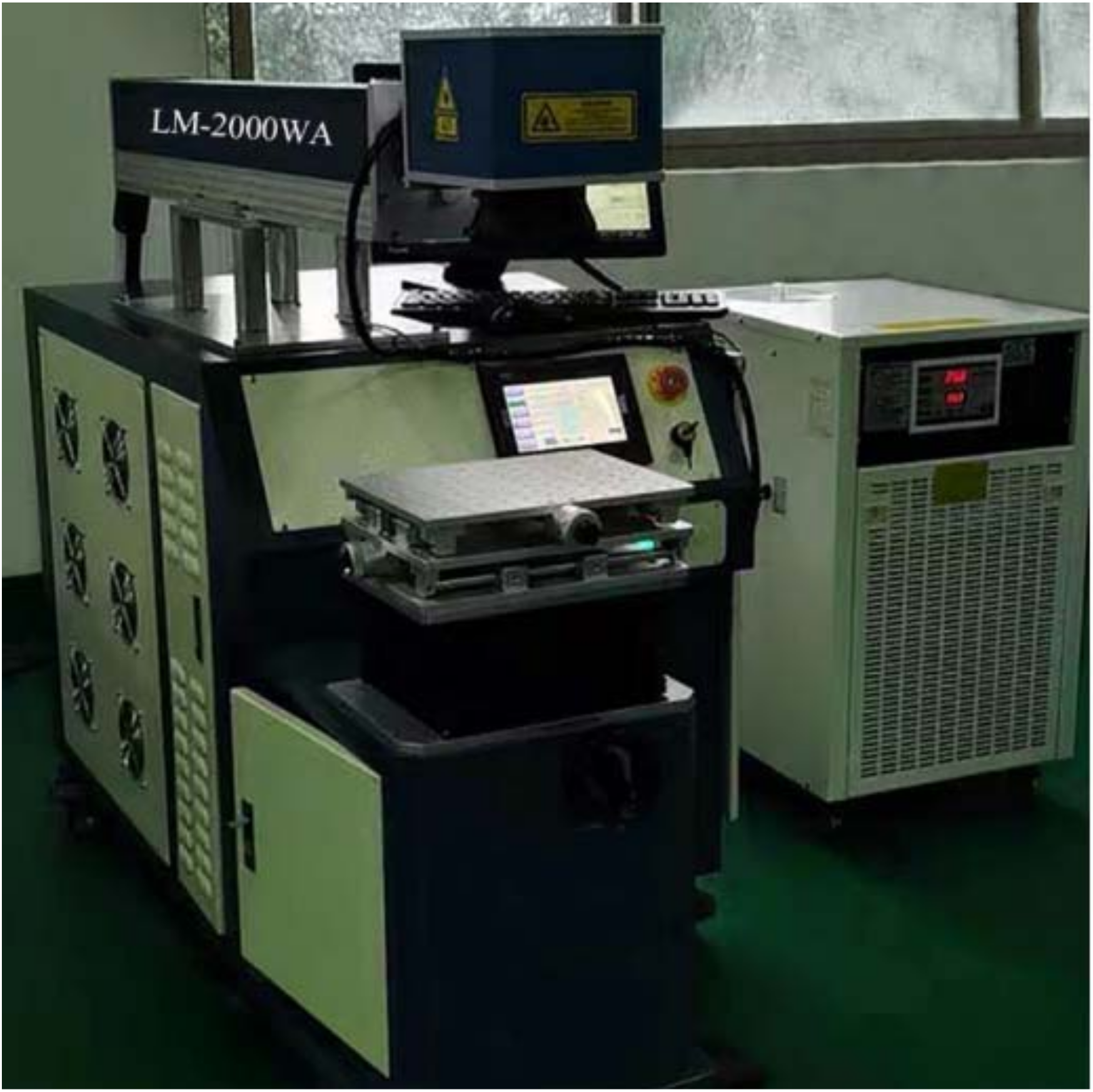
2.1. Preparation
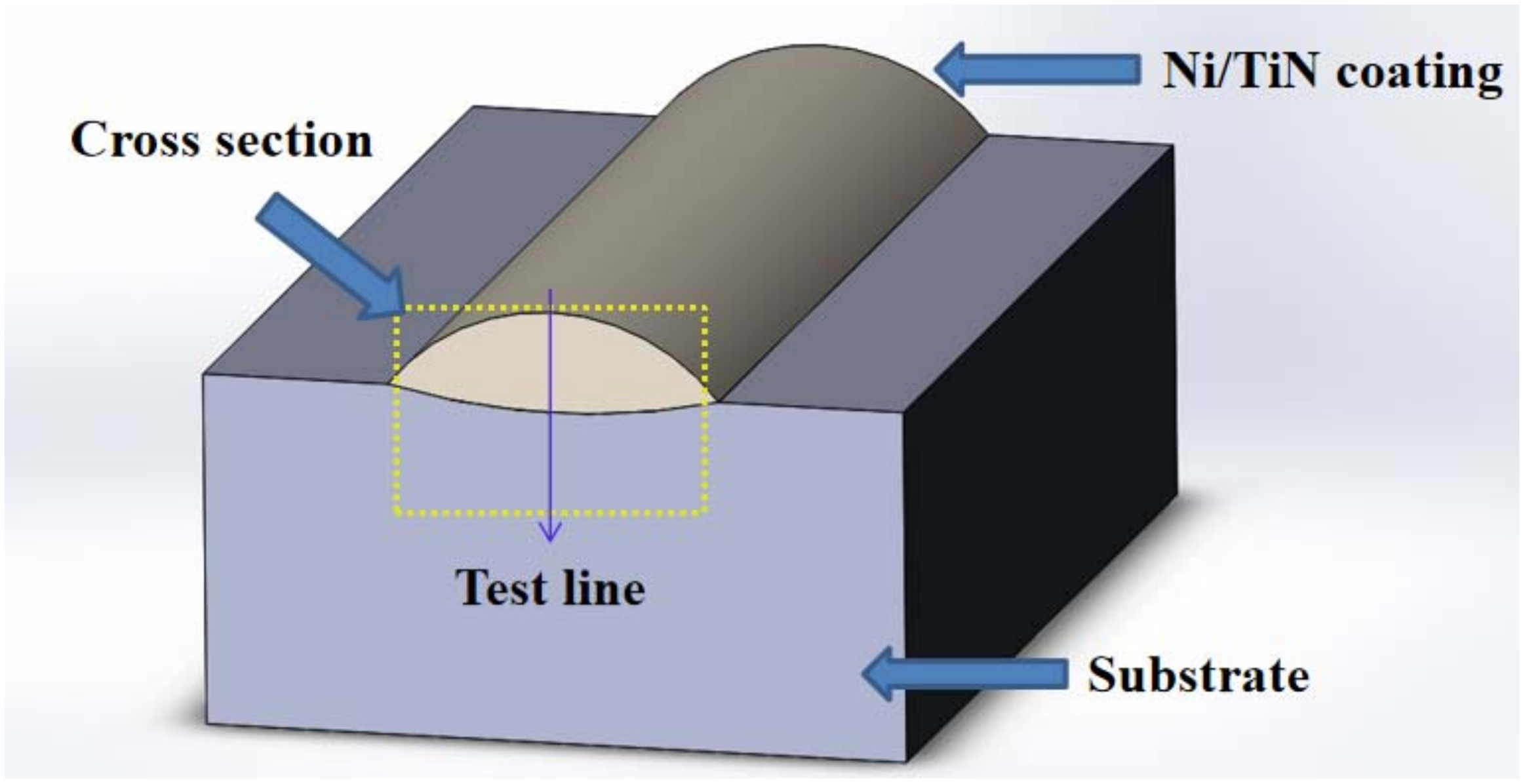
2.2. Measurement
3. Results and Discussion
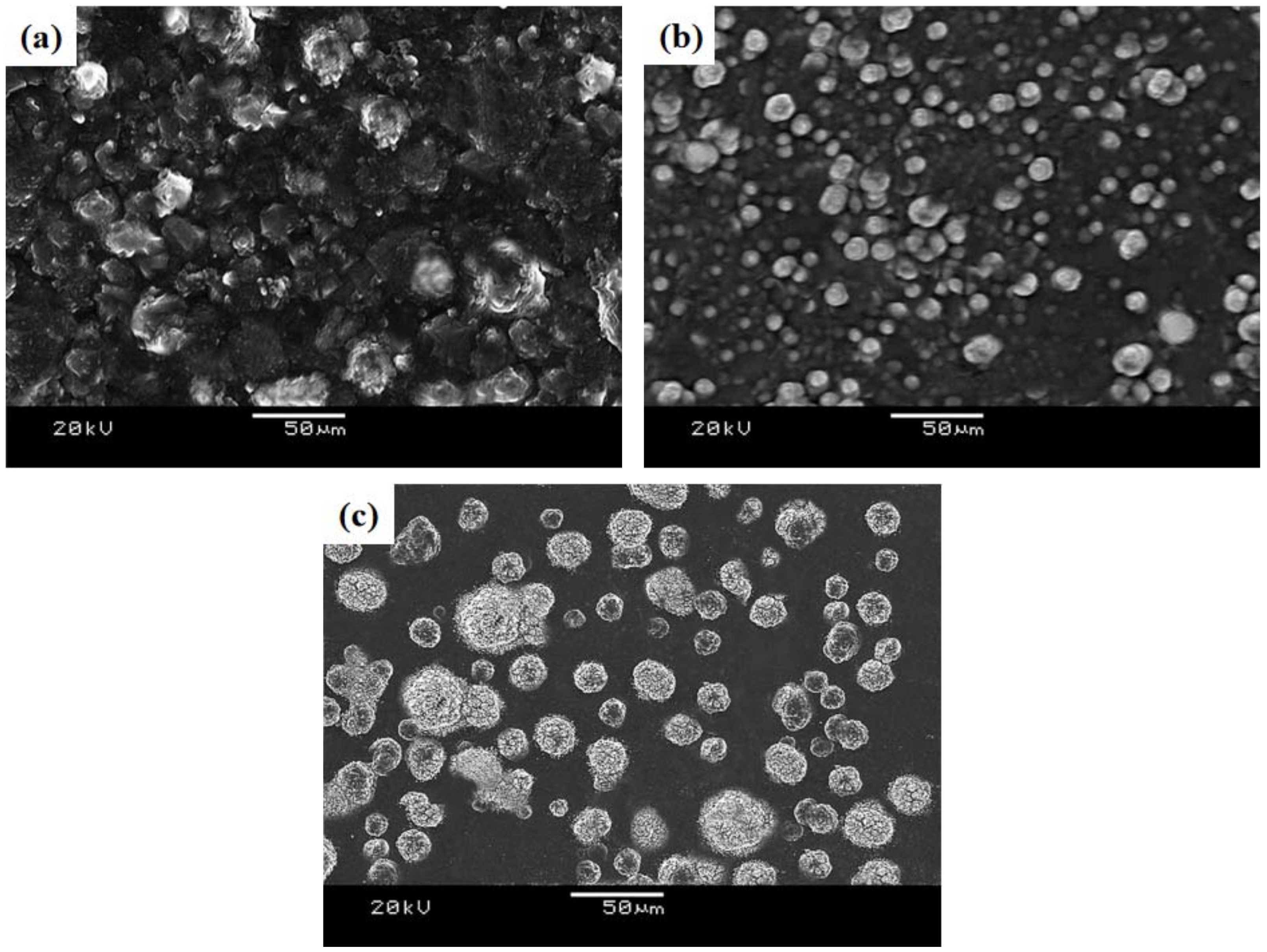
3.1. Surface Morphology
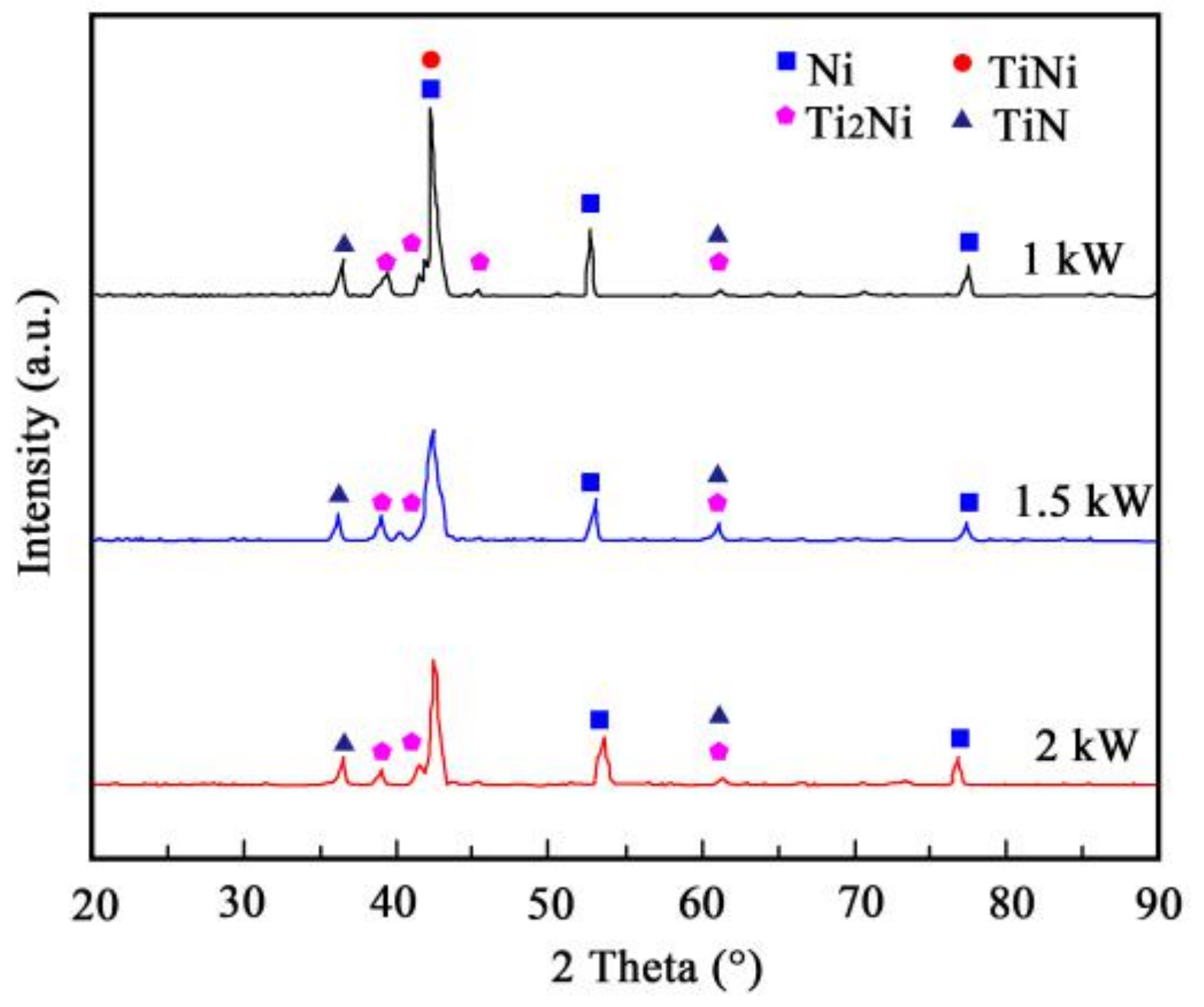
3.2. XRD Analysis
3.3. Micorhardness Test
3.4. Shear Strength Test
3.5. Wear Resistance Measurement
4. Conclusions
- (1)
- The Ni/TiN coating deposited at 1 kW exhibited a coarse morphology with large TiN particles. Among the three coatings, the Ni/TiN coating deposited at 1.5 kW processed fine grains that were evenly dispersed and had a compact microstructure. The Ni/TiN coating displayed a face-centered cubic (fcc) lattice, which exhibited a variety of orientations due to the laser powers.
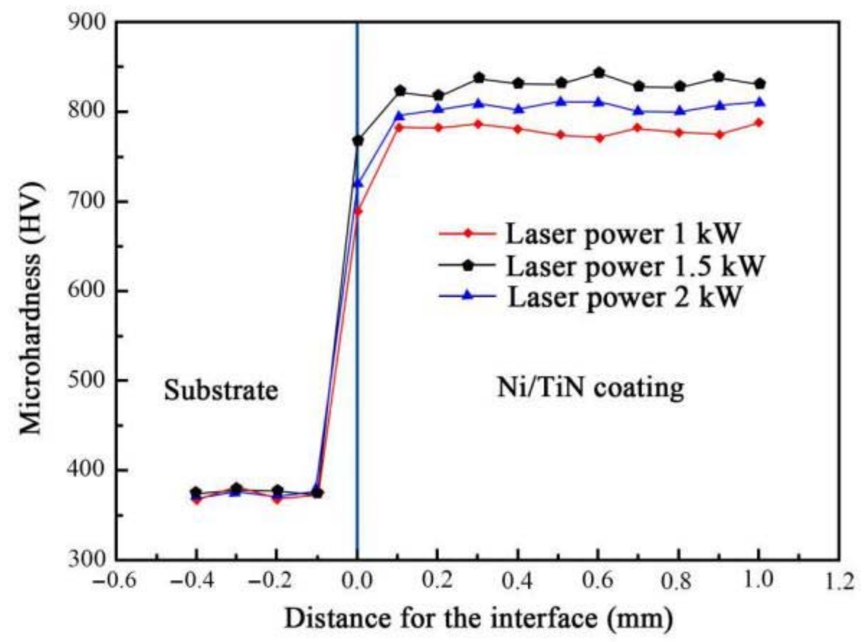
- (2)
- The Ni/TiN coating deposited at 1 kW had an average microhardness of 768 HV, the lowest of the three coatings, whereas the Ni/TiN coating deposited at 1.5 kW had a maximum average microhardness of 843 HV. However, the Ni/TiN coating processed an average hardness of 808 HV when prefabricated at 2 kW.
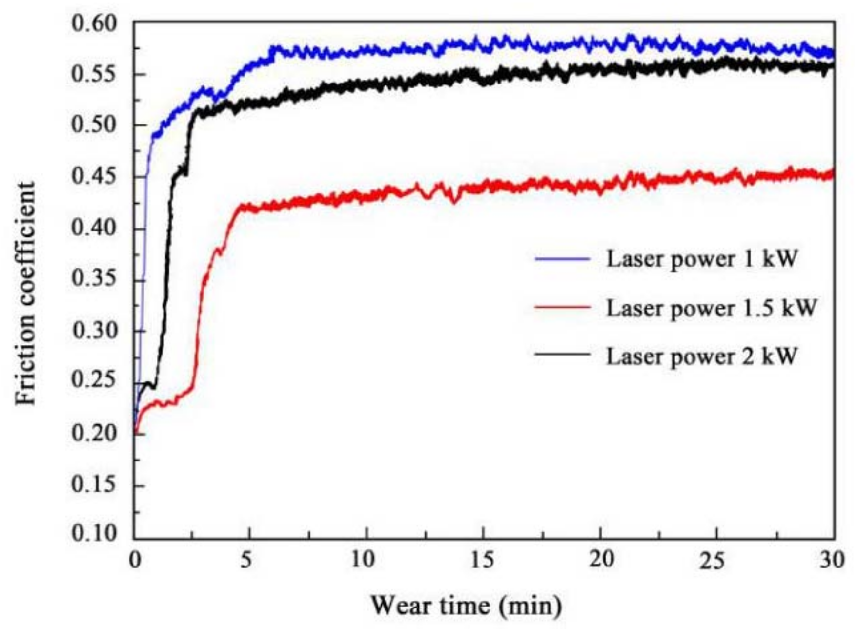
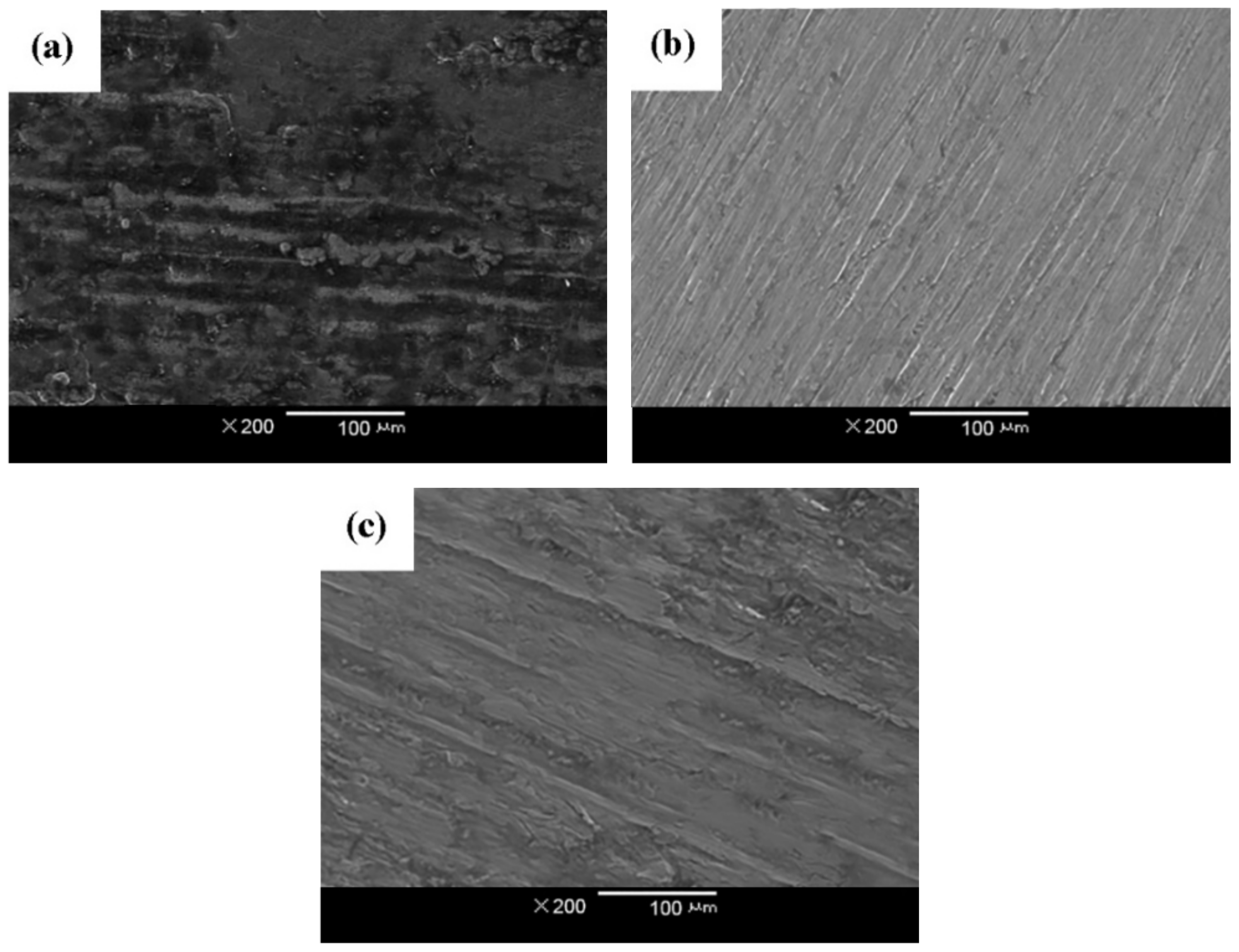
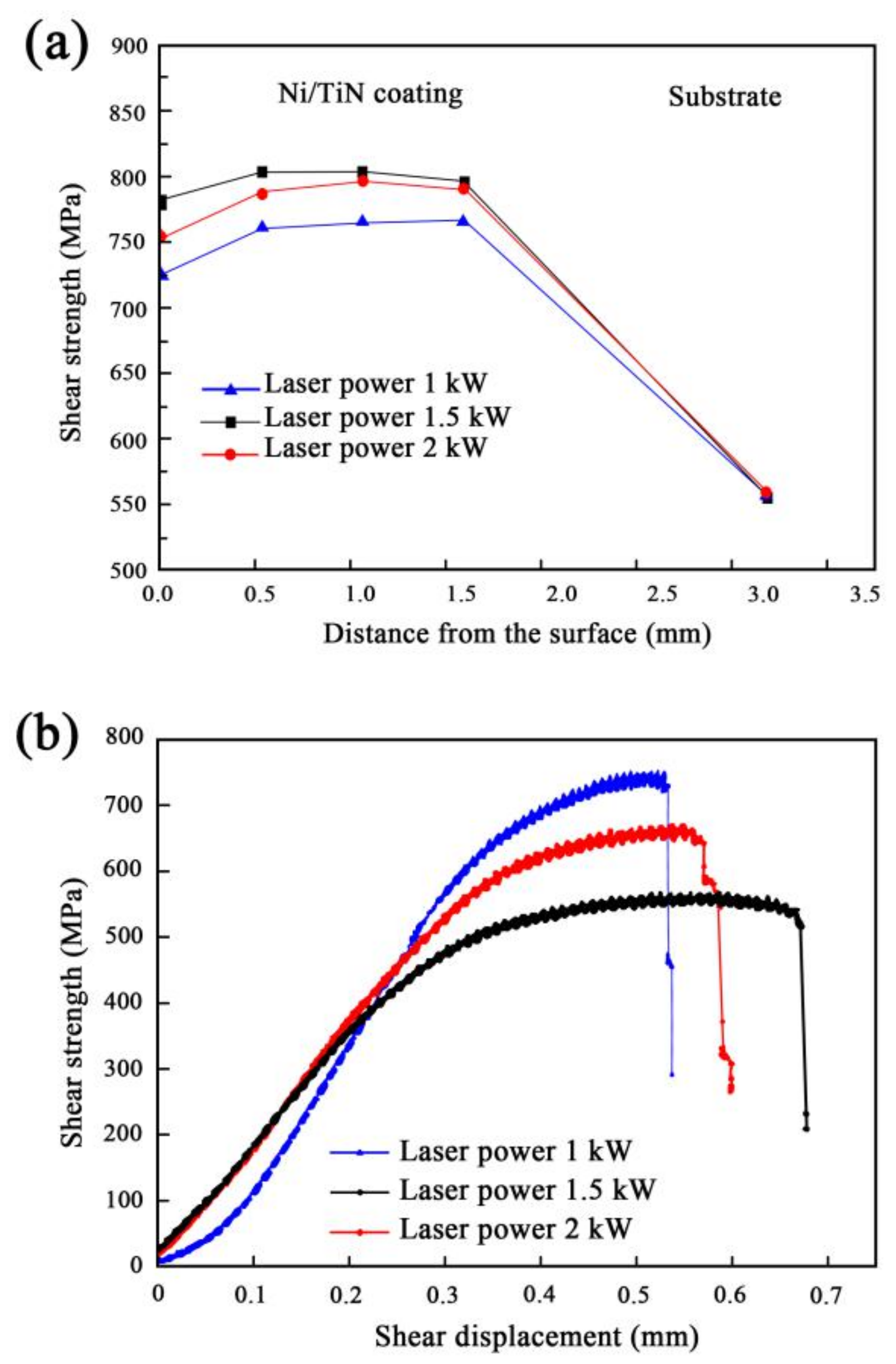
- (3)
- The Ni/TiN coating deposited at 1.5 kW processed an average shear strength of 802 MPa, which was significantly higher than the shear strengths of the other coatings. The shear displacements of the Ni/TiN coatings obtained at 1, 1.5, and 2 kW were 0.68, 0.54, and 0.61 mm, respectively. The Ni/TiN coating produced at 1.5 kW had the lowest friction coefficient of all coatings, with an average value of only 0.44. Additionally, the Ni/TiN coating deposited at 1.5 kW had the best wear resistance of the three coatings.
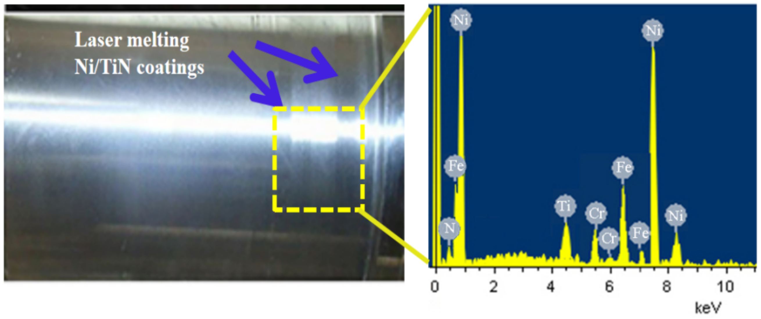
- (4)
- The Ni/TiN coating was tightly combined with the shaft after grinding. Ni, Ti, N, Cr, and Fe elements appeared on the surface of the shaft of the ESP, indicating that the LMD technology had successfully repaired the shaft of the ESP.
Author Contributions
Funding
Institutional Review Board Statement
Informed Consent Statement
Data Availability Statement
Conflicts of Interest
References
- Yan, S.; Luo, X.; Sun, S.; Zhang, L.; Chen, S.; Feng, J. Influence of inlet gas volume fraction on energy conversion characteristics of multistage electric submersible pump. J. Petrol. Sci. Eng. 2021, 207, 109164. [Google Scholar] [CrossRef]
- Reges, G.; Fontana, M.; Ribeiro, M.; Silva, T.; Schnitman, L. Electric submersible pump vibration analysis under several operational conditions for vibration fault differential diagnosis. Ocean Eng. 2020, 219, 108249. [Google Scholar] [CrossRef]
- Martins, J.R.; Ribeiro, D.D.C.; Assis, F.D.; Pereira, R.; Romero, O.J. Heat dissipation of the electrical submersible pump (ESP) installed in a subsea skid. Oil Gas Sci. Technol. 2020, 75, 13. [Google Scholar] [CrossRef]
- Liu, Z.; Sun, B.; Wang, Z.; Lou, W.; Zhang, J. Modeling of multiphase flow in marine gas hydrate production system and its application to control the production pressure difference. J. Nat. Gas Sci. Eng. 2020, 85, 103687. [Google Scholar] [CrossRef]
- Burkov, A.; Kulik, M.; Krutikova, V. Electrospark deposition of tungsten carbide powder on titanium alloy Ti6Al4V. Lett. Mater. 2021, 11, 175–180. [Google Scholar] [CrossRef]
- Choi, K.H.; Han, S.K.; Lee, T.H. Electrode fabrication for proton exchange membrane fuel cells by pulse electrodeposition. J. Power Sources 1998, 75, 230–235. [Google Scholar] [CrossRef]
- Krysina, O.V.; Yu, F.I.; Koval, N.N.; Prokopenko, N.A.; Shugurov, V.V.; Petrikova, E.A.; Tolkachev, O.S. Composition, structure and properties of Mo-N coatings formed by the method of vacuum-arc plasma-assisted deposition. Surf. Coat. Technol. 2021, 416, 127153. [Google Scholar] [CrossRef]
- Wang, L.; Gao, M.; Zhang, C.; Zeng, X. Effect of beam oscillating pattern on weld characterization of laser welding of AA6061-T6 aluminum alloy. Mater. Des. 2016, 108, 707–717. [Google Scholar] [CrossRef]
- Xia, Y.; Chen, H.; Liang, X.; Lei, J. Circular oscillating laser melting deposition of nickel-based superalloy reinforced by WC: Microstructure, wear resistance and electrochemical properties. J. Manuf. Process. 2021, 68, 1694–1704. [Google Scholar] [CrossRef]
- An, Q.; Xia, Z.X.; Zhang, C.; Yang, Z.G.; Chen, H. Effect of thermal cycles on microstructure of reduced activation steel fabricated using laser melting deposition. J. Iron Steel Res. Int. 2021, 28, 316–326. [Google Scholar] [CrossRef]
- Salman, O.O.; Gammer, C.; Chaubey, A.K.; Eckert, J.; Scudino, S. Effect of heat treatment on microstructure and mechanical properties of 316L steel synthesized by selective laser melting. Mater. Sci. Eng. 2019, 748, 205–212. [Google Scholar] [CrossRef]
- Xia, F.; Li, C.; Ma, C.; Li, Q.; Xing, H. Effect of pulse current density on microstructure and wear property of Ni-TiN nanocoatings deposited via pulse electrodeposition. Appl. Surf. Sci. 2021, 538, 148139. [Google Scholar] [CrossRef]
- Li, W.Y.; Zhang, G.; Liao, H.L.; Coddet, C. Characterizations of cold sprayed TiN particle reinforced Al2319 composite coating. J. Mater. Process. Technol. 2008, 202, 508–513. [Google Scholar] [CrossRef]
- Chi, F.; Schmerling, M.; Eliezer, Z.; Marcus, H.L.; Fine, M.E. Preparation of Cu-TiN alloy by external nitridation in combination with mechanical alloying. Mater. Sci. Eng. A 1995, 190, 181–186. [Google Scholar] [CrossRef]
- Li, X.; Zhu, Y.; Xiao, G. Application of artificial neural networks to predict sliding wear resistance of Ni–TiN nanocomposite coatings deposited by pulse electrodeposition. Ceram. Int. 2014, 40, 11767–11772. [Google Scholar] [CrossRef]
- Wu, M.; Jia, W.; Lv, P. Electrodepositing Ni-TiN nanocomposite layers with applying action of ultrasonic waves. Procedia Eng. 2017, 174, 717–723. [Google Scholar] [CrossRef]
- Peng, X.S.; Li, Y.P.; Zhang, X.M.; Wang, S. Prediction on corrosion rate of Ni-TiN coatings by BP neural network. J. Synth. Cryst. 2016, 45, 2556–2560. (In Chinese) [Google Scholar]
- Wang, W.; Qian, S.Q.; Zhou, X.Y. Microstructure and properties of TiN/Ni composite coating prepared by plasma transferred arc scanning process. Trans. Nonferrous Met. Soc. China 2009, 19, 1180–1184. [Google Scholar] [CrossRef]
- Kumar, M.; Mitra, R. Effect of substrate temperature and annealing on structure, stress and properties of reactively co-sputtered Ni-TiN nanocomposite thin films. Thin Solid Films 2017, 624, 70–82. [Google Scholar] [CrossRef]
- Sun, W.; Jin, S.; Yu, Y. Preparation and characterization of Ni-TiN ultrafine powder. Powder Metall. Technol. 2000, 332, 356–361. [Google Scholar]
- Zhu, X.B.; Cai, C.; Zheng, G.Q.; Zhang, Z. Electrodeposition and corrosion behavior of nanostructured Ni-TiN composite films. Trans. Nonferrous Met. Soc. China 2011, 21, 2216–2224. [Google Scholar] [CrossRef]
- He, X.Y. Cause analysis of turbine rotor’s shaft neck damage and the repair. Power Equip. 2009, 23, 170–172. (In Chinese) [Google Scholar]
- Shchurova, A.V. Modeling the turbine rotor journal restoration located on cylindrical surface of the supporting bearer. Procedia Eng. 2017, 206, 1142–1147. [Google Scholar] [CrossRef]
- El-Genk, M.S.; Tournier, J.M. A review of refractory metal alloys and mechanically alloyed-oxide dispersion strengthened steels for space nuclear power systems. J. Nucl. Mater. 2005, 340, 93–112. [Google Scholar] [CrossRef]
- Zhang, X.P.; Zhang, Z.K.; Cui, Z.L. Preparation and characteration of nano-TiN particles. J. Qingdao Univ. Sci. Technol. 2004, 3, 235–237. [Google Scholar]
- Wang, R.J.; Liang, J.L.; Huang, X.Y.; Shi, H.X. Microstructure and corrosion properties of laser cladding CoCrW coating on 37Mn5 steel surface of oil and gas pipeline. Mater. Sci. Eng. Power Metall. 2020, 25, 475–479. [Google Scholar]
- Chen, X.; Cheng, H.Y. Graphical simulation for microstructures of Ni-TiN coatings using cellular automata model. Adv. Mater. Res. 2014, 912, 154–157. [Google Scholar] [CrossRef]
- Fang, H.; Wang, S.; Chen, R.; Xu, Q.; Yan, Y.; Su, Y.; Guo, J. The effects of the formation of a multi-scale reinforcing phase on the microstructure evolution and mechanical properties of a Ti2AlC/TiAl alloy. Nanoscale 2021, 13, 12565–12576. [Google Scholar] [CrossRef]
- Nur-E-Alam, M.; Rahman, M.M.; Basher, M.K.; Vasiliev, M.; Alameh, K. Optical and chromaticity properties of metal-dielectric composite-based multilayer thin-film structures prepared by RF magnetron sputtering. Coatings 2020, 10, 251. [Google Scholar] [CrossRef] [Green Version]
- Li, L.; Sun, F.; Zhang, Y.C. Effect of solution treatment on the performance of laser cladding Satellite 6 alloy coating. Surf. Technol. 2017, 46, 78–81. [Google Scholar]


Publisher’s Note: MDPI stays neutral with regard to jurisdictional claims in published maps and institutional affiliations. |
© 2022 by the authors. Licensee MDPI, Basel, Switzerland. This article is an open access article distributed under the terms and conditions of the Creative Commons Attribution (CC BY) license (https://creativecommons.org/licenses/by/4.0/).
Share and Cite
Wang, Y.; Gao, W. Microstructure and Performance of Ni/TiN Coatings Deposited by Laser Melting Deposition on 40Cr Substrates. Coatings 2022, 12, 367. https://doi.org/10.3390/coatings12030367
Wang Y, Gao W. Microstructure and Performance of Ni/TiN Coatings Deposited by Laser Melting Deposition on 40Cr Substrates. Coatings. 2022; 12(3):367. https://doi.org/10.3390/coatings12030367
Chicago/Turabian StyleWang, Yan, and Wang Gao. 2022. "Microstructure and Performance of Ni/TiN Coatings Deposited by Laser Melting Deposition on 40Cr Substrates" Coatings 12, no. 3: 367. https://doi.org/10.3390/coatings12030367
APA StyleWang, Y., & Gao, W. (2022). Microstructure and Performance of Ni/TiN Coatings Deposited by Laser Melting Deposition on 40Cr Substrates. Coatings, 12(3), 367. https://doi.org/10.3390/coatings12030367