Abstract
As a very common type of laser additive manufacturing technology, laser material deposition (LMD) is widely used, having exceptional application advantages including surface enhancing, repairing damaged parts with high value-add, and building functionally graded material. At present, the continuous wave laser is a common laser mode used in the LMD process. The investigation of pulse shaping, which can add a degree of control over the thermal history, is limited. In this study, the effects of pulse shaping on the geometrical characteristics, microstructure, and microhardness were investigated through conducting single-track experiments with different laser shapes, including continuous, rectangular, ramp up, ramp down, and hybrid ramp. The results indicated that the clads created by continuous and ramp up laser shape presented the maximum and minimum dimensions of geometrical characteristics, respectively. The rectangular and hybrid ramp laser shape deposited the clads with similar dimensions. The continuous laser shape produced the clad with the coarsest microstructure and lowest hardness because of the lowest cooling rate. The smallest grain size and highest hardness presented in the clad were seen with the rectangular laser shape owing to the biggest cooling rate. The cooling rates in ramp up and ramp down were restrained by the gradual heating and gradual cooling, respectively.
1. Introduction
Compared to conventional subtractive manufacturing processes such as turning and milling in which products can be fabricated by removing material from a large stock or sheet, additive manufacturing (AM), whereby the material is added layer upon layer to produce a 3D object directly from a computer aided design (CAD) model without attendance of any molds or tools, possesses many superiorities like energy saving, reduction of costs, improvement of material utilization, etc. [1,2,3]. As a very common type of additive manufacturing technology, laser material deposition (LMD) is widely applied in the areas of aviation, aerospace, die and mold, etc. In particular, laser material deposition has excellent future promise in the applications of surface enhancing, repairing damaged parts with high value-added, and building functionally graded material [3,4,5]. These applications are currently unfulfillable based on the powder bed fusion in which powder is preset by the scraper [4,5,6]. In the laser material deposition process, a high-powered laser beam acts as heating energy to create a molten pool on the surface of substrate, and the metallic powder is delivered from the powder nozzle into the molten pool simultaneously by a flowing inner gas (such as Argon) [7]. The molten pool captures the delivered powder and increases the volume. The molten pool solidifies rapidly once the laser beam goes away. As the laser beam and powder nozzle move along the path planned by the computer, the track is created. Based on the planned profile, the first layer is deposited on the substrate through overlapping of adjacent tracks. Afterwards, the laser cladding head elevates the height of the Z-increment to the position of the new layer. The first layer serves as the “substrate” for the deposition of new layer. The new layer is deposited by creating metallurgical bonding with the first layer along the profile under the guidance of computer. A similar process, in which latter layers are sequentially created on the preceding layer, is repeated to build a three-dimensional (3D) part layer-by-layer [8,9]. Owing to the features of the laser beam and layer-by-layer process, laser material deposition possesses advantages including high production flexibility, low thermal inputting, and high geometry freedom [10,11].
At present, the continuous wave laser is a common laser mode used in the laser material deposition process. Compared to conventional heating sources such as plasma, the continuous wave laser produces relatively low inputted heat but has a high temperature gradient and high cooling rate during laser beam scanning. Therefore, the part would be manufactured with a refined microstructure and superior erosion resistance [12]. The microstructure of the deposition created by the laser material deposition presents a typical solidification structure which consists of a cellular region near the top surface, a dendritic region in the central section and a planar interface in the deposition layers. The deposition layer has the characteristics of high hardness and high strength, but low ductility [13,14]. The laser material deposition process is accompanied by rapid melting and solidification during the moving of the laser beam that prompts large residual stress and deformation [1].
A pulsed laser emits bursts of energy consisting of a fixed amount of energy for a specified duration [15]. Compared to a continuous wave laser, a pulsed laser generates lower inputted heat reached on the surface of substrate. The interval time between adjacent laser pulses provides a blanking time for the cooling and solidification of the molten pool. Thus, the deposition layer presents a more refined microstructure and higher hardness. The controllability of the residual stress can be improved with the application of pulse laser [16,17]. Therefore, numerous studies have made efforts to investigate the deposition of pulsed laser material deposition (P-LMD). Tao et al. conducted the Ni60 deposited experiments of single-track, single layer, multi-track, and multi-layers by P-LMD. The effects of laser power, scanning speed, and defocusing on the geometrical characteristics were investigated. They pointed out that the ratio of remelting depth to height can act as the criterion to judge the reasonability of laser power. The ratio cannot be beyond one, meaning that the height should be bigger than depth. The hardness of Ni60 deposition can reach up to 830 HV [18]. Sun et al. deposited Stellite 6 powder on stainless steel by P-LMD and investigated the effects of pulsed laser energy, frequency, powder feed rate, and overlap rate on the deposition height, dilution, and heat affected zone (HAZ). The results indicated that the height and depth increased with the increase of pulsed laser energy, frequency, and overlap rate. The hardness decreased with the increase of dilution. If the overlap rate was 89% of width, the crack would be free, and the crack would present with the decrease of overlap rate. However, if the overlap rate was less than 33% of width, the crack would disappear because of the remelting and heat treatment caused by the deposition of the new layer [19]. Toyserkani developed a 3D finite model to investigate the relationship between the geometrical characteristics of deposition and pulse laser energy as well as frequency. Based on the comparison between the theoretical and experimental results, they proposed the function of geometrical characteristics of deposition with the effective powder concentration and power density [20]. Shah created the Inconel 718 deposition on a Ti-6Al-4V substrate to study the effect of process parameters on the feature of molten pool. The results showed that the disturbance of molten surface aggravated with the increase of powder feed rate and the applying of pulsed laser. There was a negative correlation between the disturbance of molten pool surface and surface roughness that means the surface roughness would decrease and the quality of deposition would improve with the aggravation of disturbance of surface. The area of molten pool decreased with the increase of powder feed rate and the decrease of carrier gas [2]. Dong conducted the deposited experiment on the thin-wall blade by P-LMD and investigated the effect of process parameters on the geometrical characteristics of deposition. The results indicated that the depth, height, and width increased with the increase of the duty cycle. They pointed out that the problem of crack and edge collapse can be solved and thermal injury can be alleviated with the attendance of pulsed laser [21]. Gharbi et al. studied the influence of a pulsed laser regime on the surface finish induced by LMD on a widely used titanium alloy (Ti6Al4V). Their finding confirmed that high mean power improved surface finish and using a pulsed mode with large duty cycles was clearly shown to provide smoothening effects [22].
Pulse shaping is a technique used to control the temporary distribution of energy within a single laser pulse through changing the laser waveform. It also can be defined as a variation in power supplied to a laser to change the shape of the output pulse and subsequently the heat distribution within the pulse. Therefore, the degree of control over the heat delivered to the laser material interaction zone would be added. The melting behavior of a material would be completely changed with the change of energy distribution within a pulse [15]. Mumtaz fabricated the Inconel 625 thin-wall part by selective laser melting and investigated the effect of pulse shaping on the width and roughness of the thin-wall part. The results indicated that the splash of powder in the fabricating process is alleviated, the quality of deposition improves, and the width decreases owing to the use of pulse shaping [15].
Up to now, few investigations have been reported about laser material deposition using pulse shaping. This work conducted single-track deposition experiment to investigate the effects of pulse shaping on the geometrical characteristics (width, height, and depth), microstructure, and microhardness of single-track clad based on different shapes of laser. In addition, the effect of thermal history created by different shapes of laser on the cooling rate of molten pool in the laser material deposition process was analyzed.
2. Materials and Methods
2.1. Materials
The gas atomized AISI316L austenitic stainless steel powder produced by Höganäs (Ath, Belgium) was chosen as the depositing material. The powder has a particle size range of 45–150 μm. The chemical composition of the powder is shown in Table 1. The deposition was conducted on the AISI316L stainless steel plate with dimensions of 120 mm × 60 mm × 6 mm. The surface of the substrate was polished and then cleaned by acetone for the depositing process.

Table 1.
Chemical composition of AISI316L stainless steel powder.
2.2. Experimental Set-Up
The AISI316L single-track clads were deposited on an LMD system (Yuchen, Anshan, China) in which the laser shape can be controlled by changing the parameters of the laser generator. As shown in Figure 1, the LMD system consisted of a LaserLine diode laser generator (LMD 4000-100, LaserLine, Mülheim-Kärlich, Germany) with 4000 W maximum power supply, a Kuka six-axes robot (ZH 30/60III, KUKA, Augsburg, Germany), a Precitec laser cladding head (YC52, Precitec, Rotenfels, Germany) with four coaxial nozzles, and a Raycham mental powder feeder (RC-PGF-D, Yuchen, Anshan, China). In the deposition process, the inert gas (Argon) with 99.99% purity was used as the carrier gas and shielding gas with flow rates of 400 L/h and 600 L/h, respectively.
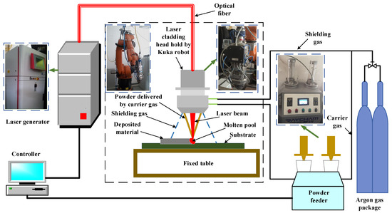
Figure 1.
Schematic illustration of the laser material deposition (LMD) system.
2.3. Pulse Shaping and Parameters
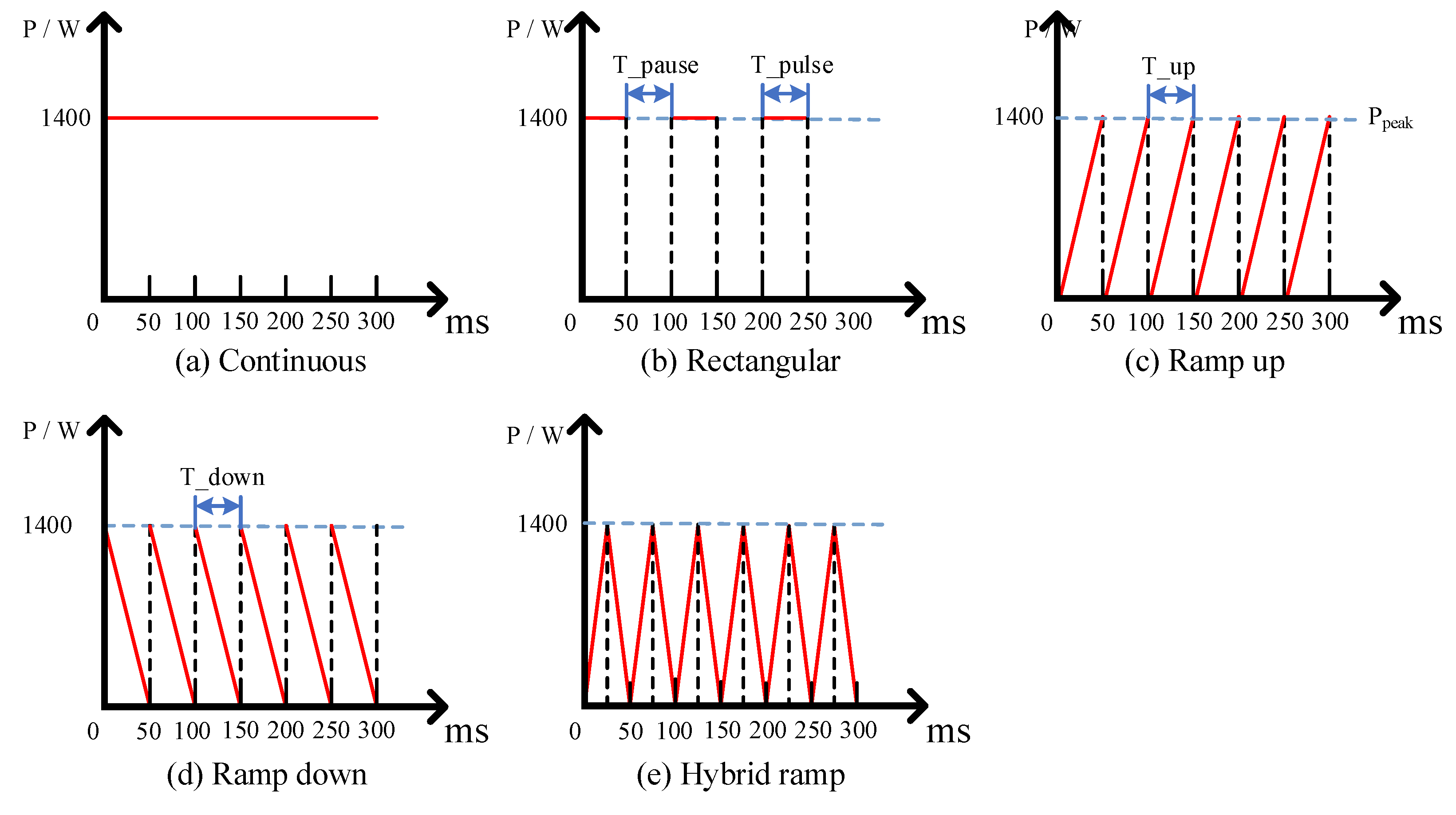
The single-track clads were created with five types of laser shape including continuous, rectangular, ramp up, ramp down, and hybrid ramp laser wave which are shown in Figure 2 with the continuous laser shape set as comparison. In all deposition experiments, the laser peak power, scanning speed, and powder feed rate were kept constant with values of 1400 W, 6 mm/s, and 0.078 g/s, respectively. Continuous and rectangular laser shape are the two most common used laser modes in the present research of laser material deposition. In the rectangular laser shape, the emitted laser energy is invariable during the pulse duration. Compared to the continuous laser, the T_pause of the rectangular laser, as shown in Figure 2b, provides the time for cooling of the molten pool. In the ramp up laser shape, the maximum laser energy is set at the end of a pulse meaning that the laser emitted process would take T_up from zero to reach the laser peak power, as shown in Figure 2c. In the laser shape of ramp down, the maximum laser energy is set at the beginning of a pulse, meaning that the laser emitted process would take T_down from the laser peak power to reach zero (Figure 2d). The hybrid laser shape is the mix of ramp up and ramp down. Referring to the experimental material and our previous research works, the processing parameters, including laser peak power (Ppeak), scanning speed (V), powder feed rate (Qm), T_pulse, T_pause, T_up, and T_down, were determined, as listed in Table 2.
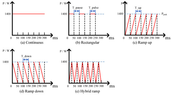
Figure 2.
Schematic illustration of the five types of laser shape: (a) continuous, (b) rectangular, (c) ramp up, (d) ramp down, and (e) hybrid ramp laser shape.
Table 2.
Process parameters for experiments.
2.4. Characterization Techniques
The experimental samples were obtained from the LMD depositions using the wire electrical discharge machine and then mechanically polished. The geometrical characteristics (height, width, and depth) of single-track clads were determined by measuring the cross-section of single-track in which the measurement was conducted, repeated three times for each sample, using a metallographic microscope (Leica-DMi8, Leica, Wetzlar, Germany). The microstructure of the sample was observed by metallographic microscope after being chemically etched in oxalic acid saturated solution. The microhardness was determined by a Vickers microhardness tester (HV-1000, Fangyuan, Jinan, China).
3. Results
As a common used laser mode in the present research of laser material deposition, continuous wave laser could provide stable laser energy inputting. However, the laser does not have to unremittingly emit because there is sufficient laser energy for fully melting the material. Furthermore, the unremitting laser inputting would hinder the molten pool to solidify. Compared to the continuous laser, the interval time of the rectangular laser, which is T_pause as shown in Figure 2b, provides the time for cooling of the molten pool which contributes to an increase of the cooling rate and a more refined microstructure as well as mechanical properties. However, the residual stress, which might result in dislocation and lead to poor mechanical properties, is easier to generate because of the higher cooling rate of molten pool [23,24,25]. In the laser shape of ramp up, because the laser power reaches up to peak power gradually from zero as shown in Figure 2c, the ramp up process equals a gradually heating process that contributes to the warmth of the substrate and decreases the temperature difference between the top and bottom of the molten pool. This is be beneficial for decreasing cracks. In the laser shape of ramp down, owing to the gradually reduction of laser power from the peak power to zero as shown in Figure 2d, the ramp down process equals a gradually cooling process, which means a decrease of the cooling rate. The lower cooling rate would contribute to the reduction of residual stress. However, a coarser microstructure and lower hardness would result. The hybrid ramp laser shape as shown in Figure 2e, which mixes the ramp up and ramp down laser shapes, signifies complex inputting and contribution of laser energy that offers greater possibilities to control the thermal history during the deposition process and the mechanical properties of deposition by LMD [26,27,28].
3.1. Geometrical Characteristics
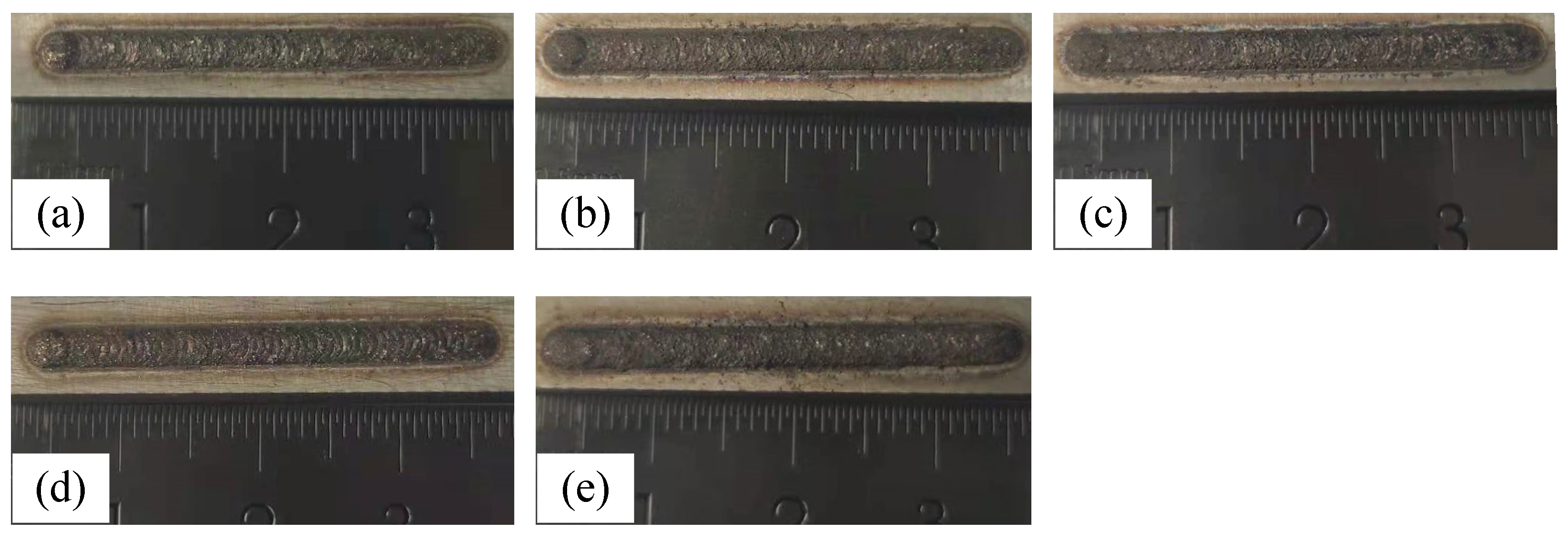
In the LMD process, the part is fabricated layer by layer. It is indicated that the geometrical characteristics and quality of each layer, especially the first layer on the substrate, have a significant effect on the process stability and properties of the final deposited part because of the continuous deposition process [29,30]. The investigation of effects of process parameters on the geometrical characteristics (width, height, and depth) is the foundation for deposition of complex parts by LMD. Referring to the reported researchers, there are many parameters, including laser power, powder feed rate, scanning speed, flow rates of carrier and shielding gas, defocusing, and dimeter of laser spot. The laser power, powder feed rate, and scanning speed are the most important parameters affecting the geometrical characteristics of deposition. With the decrease of scanning speed and increase of laser power as well as powder feed rate, the width increases. The height is mainly affected by scanning speed and powder feed rate. With the increase of scanning speed, the depth decreases [31]. In this study, the scanning speed, powder feed rate, and laser peak power were kept constant but the equivalent pulse energy was different owing to the change of laser shape. The equivalent pulse energy was related to the parameters of T_pulse, T_pause, T_up, and T_down. Figure 3 shows the images of single-track clads deposited by LAM with different laser shapes. It can be seen that the full appearance clads with high quality were deposited by five types of laser shapes. It is worth noting that only the clad deposited by ramp down laser shape presented obvious trails of overlapping between the adjacent laser spot as shown Figure 3d. Owing to the existing of T_up and T_down during the conditions of ramp up and ramp down laser shapes, the equivalent pulse energy in those two conditions was low compared to the other laser shapes. The low equivalent pulse energy contributes to the solidification of molten pool [23,24,25]. However, the gradual heating in ramp up laser shape was more conductive to generation of a molten pool that resulted in an inconspicuous trail of overlapping. With the using of ramp down laser shape, the gradual cooling was more conducive to the solidification of a molten pool that contributed to the occurrence of obvious overlapping trails.
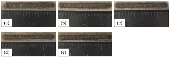
Figure 3.
Images of single-track clads deposited by LAM with (a) continuous, (b) rectangular, (c) ramp up, (d) ramp down, and (e) hybrid ramp laser shape.
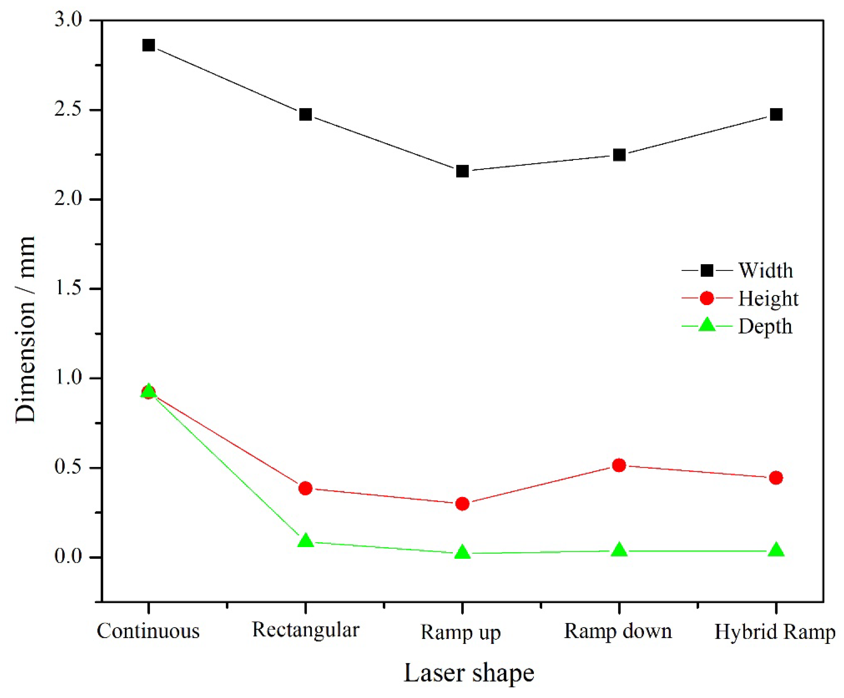
Figure 4 shows the width, height, and depth of single-track clads with different laser shapes including continuous, rectangular, ramp up, ramp down, and hybrid ramp. Compared to the other laser shapes, the dimensions of width, height, and depth of single-track clad deposited by continuous laser shape presented the maximum values. Under the condition of continuous laser shape, much laser energy inputted to the substrate was absorbed and the bigger molten pool with a higher temperature was created. As a result, the molten pool could capture much powder and increase the size. Therefore, the maximum values of width and height that occurred during the continuous laser shape were used. The minimum values of the dimensions were shown during the ramp up laser shape. The results could be explained by the fact that the ramp up and ramp down laser shapes provide the lowest equivalent laser energy. Compared to the ramp down shape, the molten pool would enlarge and heat up gradually, resulting in the slight capture of powder at the beginning of a pulse in the ramp up process. Therefore, the values of width and height in the condition of ramp up were smaller than that in the ramp down shape. In addition, using the rectangular, ramp up, ramp down, and hybrid ramp laser shapes, the values of depth were close to zero, which is attributed to the inadequate laser energy absorbed by the substrate. In the context of metallurgical bonding, the low depth is beneficial for the mechanical properties of the clads because of the low dilution [27,29].
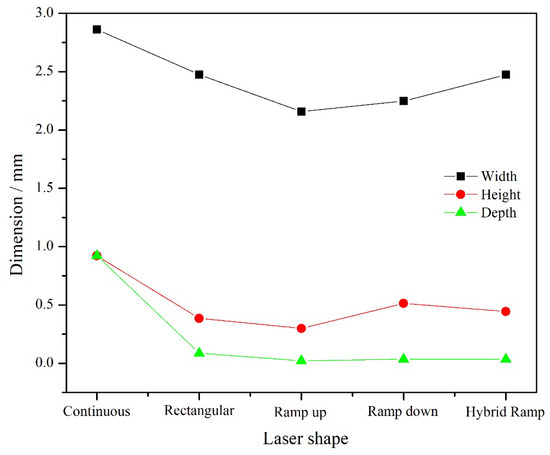
Figure 4.
The width, height, and depth of single-track with different laser shape.
It was noticed that the width, height, and depth in the condition of rectangular and hybrid ramp laser shape were approximate. During the rectangular laser shape, the parameters had a peak power of 1400 W, T_pulse of 25 ms, and T_pause of 25 ms. During the hybrid ramp shape, the parameters had a peak power of 1400W, T_pulse of 50 ms, and T_pause of 0 ms. The pulse energy was different based on the equation in which the pulse energy equals to the peak power multiplied by the T_pulse [32]. However, the T_up of 25 ms and T_down of 25 ms in the hybrid ramp shape means the equivalent pulse energy was approximately equal with that created by rectangular laser shape. Therefore, the approximate width, height, and depth were presented.
The phenomenon of dilution is a requirement to generate metallurgical bonding between the substrate and clad. The dilution, which means the elements of substrate and clad spread out into each other, stands for the changed amplitude of chemical composition of the clad [32,33]. In this study, the dilution was calculated by the ratio of depth to the sum between height and depth. Figure 5 shows the dilutions of single-track clads deposited by continuous, rectangular, ramp up, ramp down, and hybrid ramp laser shape. It can be seen that the maximum value of dilution reached up to 50% during the continuous laser shape because the high laser energy produced the biggest depth of clad. In the conditions of ramp up, ramp down, and hybrid ramp laser shape, the dilutions were small and the values were approximately 8%, assuring the metallurgical bonding between the substrate and clad. Furthermore, the lower dilution prevented the degradation of properties caused by the diffusion of the chemical element.
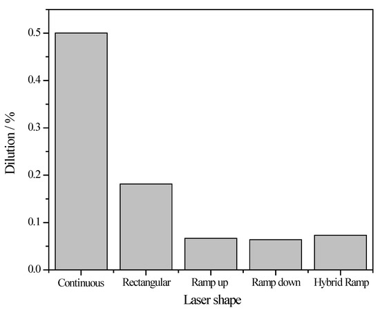
Figure 5.
The dilutions of single-track with different laser shape.
3.2. Microstructure
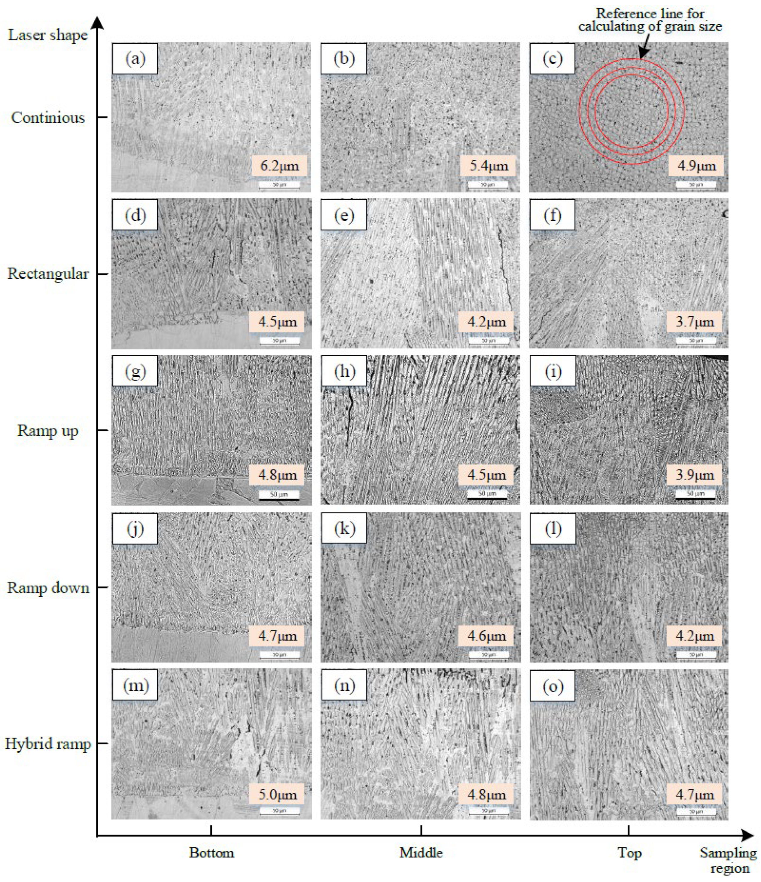
The microstructures of clad at different regions, including bottom, middle, and top of clad created by different laser shape, were observed as shown in Figure 6. Furthermore, the average grain sizes were calculated through numbering of the grains, which were traversed by three reference lines as shown in the Figure 6c. It can be seen from Figure 6 that the microstructure of depositions presented the typical solidified features, specifically the plane crystal near the interface between clad and substrate followed by the columnar cellular near the middle and cellular crystal near the top of clad [33]. The grain size gradually decreased along the direction from the interface to the top of clad.
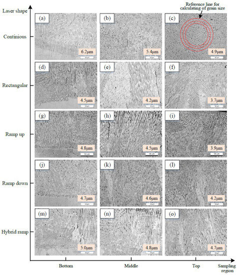
Figure 6.
The microstructures of clad at different regions of deposition created by different laser shapes. Bottom region of deposition by (a) continuous, (d) rectangular, (g) ramp up, (j) ramp down, (m) hybrid ramp laser shape; Middle region of deposition by (b) continuous, (e) rectangular, (h) ramp up, (k) ramp down, (n) hybrid ramp laser shape; Top region of deposition by (c) continuous, (f) rectangular, (i) ramp up, (l) ramp down, (o) hybrid ramp laser shape.
As shown in Figure 6, the continuous laser shape produced the coarsest microstructure compared to the microstructure deposited by the other laser shapes. The solidified microstructure was decided by the temperature gradient at the solid–liquid interface (G), solidification rate of the molten pool, and the ratio of cooling rate to thermal gradient (R). The ratio of G to R (G/R) can affect the shape of the solid–liquid interface, and the cooling rate, which is represented as G × R, controls the dimensions of the microstructure [34,35,36,37]. The grain size is closely related to the cooling rate of molten pool during the LMD process. The cooling rate has a positive correlation with the power density and a negative correlation with the deposition height [37]. The power density can be calculated by the follow equation:
where P represents the laser power, V represents the scanning speed, and d is the diameter of effective laser spot on the substrate. It can be seen from Equation (1) that the power density increases with the increase of laser power and decrease of laser spot when the scanning speed is kept constant. Compared to the other laser shapes, the equivalent laser power was high contributing to the increase of power density. However, the high equivalent laser power resulted in a big effective laser spot which can be reflected by the width of clad, as shown in Figure 3. In addition, the square of d meant the effect of the diameter of the effective laser spot would obviously be presented compared to the laser power. Thus, the grain size in continuous laser shape was big because of the low power density. Furthermore, the big value of height as shown in Figure 3 also resulted in a decrease in cooling rate, which contributed to the presentation of coarse microstructure.
The smallest grain size occurred when the rectangular laser shape was used. Compared to the rectangular condition, the grain size was bigger when the ramp up and ramp down laser shape were used. During the rectangular, ramp up, and ramp down laser shape, the parameters had peak power of 1400 W, T_pulse of 25 ms, and T_pause of 25 ms. However, the T_pulse was accompanied by T_up in ramp up laser shape and T_down in ramp down laser shape. Thus, the equivalent laser power emitted by the rectangular laser shape was higher than that of ramp up and ramp down. In addition, during the rectangular, ramp up, and ramp down laser shape, the diameters of effective laser spot were approximate, which is reflected in the results of width as shown in Figure 3. Therefore, the high equivalent laser power and approximate diameters of effective laser spot contributed to the higher cooling rate in the rectangular laser shape compared to the ramp up and ramp down laser shapes. On the other hand, the ramp up process equals a gradually heating process that contributes to the warmth of the substrate and a decrease of the temperature difference between the top and bottom of the molten pool. In addition, the ramp down process equals a gradually cooling process, which means a decrease of the cooling rate. Therefore, although the equivalent pulse energy was lower during the ramp up and ramp down condition, the cooling rates produced by the rectangular laser shape were bigger than those produced by ramp up and ramp down conditions. Thus, the smallest grain size occurred during the rectangular laser shape was used. Compared to the conditions of ramp up, ramp down, and rectangular, the grain size of deposition fabricated by the hybrid ramp laser shape was bigger. During the hybrid ramp laser shape, the parameters had a peak power of 1400 W, T_pulse of 50 ms, and T_pause of 0 ms. Although the T_up of 25 ms, T_down of 25 ms, and instantaneous interval in hybrid ramp laser shape contributed to the decrease of equivalent laser power, the approximative continuous emitting of the laser in hybrid ramp resulted in a lower cooling rate compared to the rectangular, ramp up, and ramp down laser shapes. Thus, the grain size created by the hybrid ramp laser shape was the biggest apart from the continuous laser shape.
3.3. Microhardness
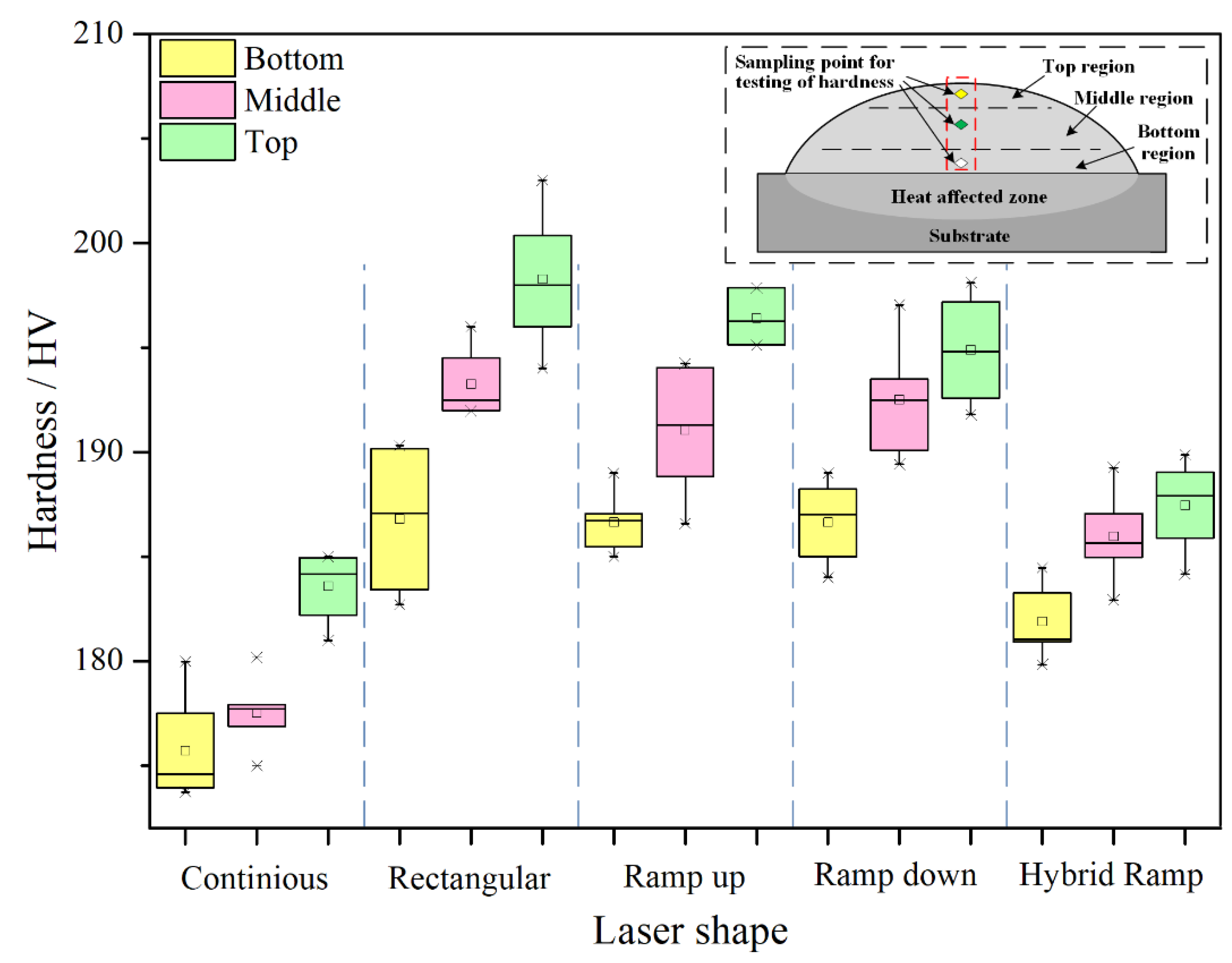
The average values of microhardness at bottom, middle, and top regions of single-track clads by five types laser shapes were obtained through testing four times and averaging the testing results for one point. The sampling points were settled along the vertical direction in every region as shown in Figure 7. The testing results of microhardness are also exhibited in Figure 7. It can be seen that the maximum average hardness of deposition was presented in the condition of the rectangular laser shape because of the smallest grain size, which was related to the biggest cooling rate, compared to the other laser shapes. The coarse microstructure of deposition created by the continuous laser shape resulted in the lowest hardness owing to the lowest cooling rate. In addition, the average hardness of deposition created by the hybrid ramp was just slightly larger than that by the continuous laser shape. As mentioned in Section 3.1, the hybrid ramp laser provides a T_pulse of 50 ms in which the T_up of 25 ms and T_down of 25 ms were included. Although the laser power increases gradually in the T_up and decreases gradually in the T_down, there was a transient interval (T_pause of 0 ms) after a hybrid ramp that means the hybrid ramp can be seen as a continuous laser shape with varied laser energy. Owing to the slightly lower equivalent pulse energy in the condition of hybrid ramp, there was a slightly bigger hardness than that produced by the continuous laser shape. Because of the existence of T_pause during the ramp up and ramp down LMD process, the lower equivalent pulse energy was inputted compared to the hybrid ramp laser shape. In addition, the bigger height of deposition was obtained. That contributes to the higher cooling rate and bigger hardness under the conditions of ramp up and down than that of the hybrid ramp laser shape. The results of grain size in Figure 5 can be well matched with the results of microhardness.
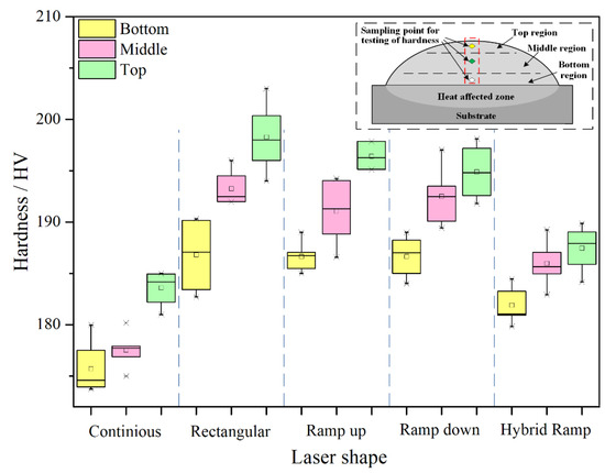
Figure 7.
Microhardness at different regions of deposition produced by different laser shape.
4. Conclusions
The effects of pulse shaping on the geometrical characteristics, microstructure, and microhardness were investigated in this paper through conducting single-track experiments using LMD with different laser shapes, including continuous, rectangular, ramp up, ramp down, and hybrid ramp. Some of conclusions can be summarized through analyzing the experimental results:
- The maximum dimensions of width, height, and depth were presented when the continuous laser shape was used because of the high laser energy input which can create a big molten pool to capture much powder. Under the condition of ramp up laser shape, the minimum values of the dimensions were shown. The results could be explained by the low laser energy input and the feature of gradual heating which restricted the growth of the molten pool in the beginning of the laser pulse. In addition, the dimension of geometric characteristics was approximate between the rectangular and hybrid ramp laser shapes owing to the approximate equivalence pulse energy.
- The microstructure of depositions presented the typical solidified features, meaning the plane crystal near the interface followed by the columnar cellular near the middle and the cellular crystal near the top. The continuous laser shape produced the coarsest microstructure with the biggest grain size as a result of the lowest cooling rate. Owing to the gradual heating in ramp up and gradual cooling in ramp down, the cooling rates were restrained under these two types of laser shape. Therefore, the smallest grain size that occurred when the rectangular laser shape was used can be attributed to the highest cooling rate.
- The rules of microhardness were well matched with the results of microstructure. The maximum average hardness of deposition was presented in the condition of rectangular laser shape because of the smallest grain size created by the biggest cooling rate. The coarse microstructure of deposition created by the continuous laser shape resulted in the lowest hardness owing to the lowest cooling rate. In addition, the average hardness of deposition created by hybrid ramp was lower than that by ramp up and ramp down. Furthermore, it was slightly larger than that of continuous laser shape because hybrid ramp can be seen as a continuous laser shape with varied laser energy.
- It can be concluded that pulse shaping has significant effects on the geometrical characteristics, microstructure, and microhardness of single-track clads deposited by LAM by affecting the laser energy input and the molten pool. In particular, the heating and cooling of the molten pool, which have serious impacts on residual stress, are closely related to the laser shape. Based on the research about single-track clad reported by this article, the investigation in regard to the effects of pulse shaping on the properties of multi-track and multi-layer depositions will be conducted in the near future.
Author Contributions
Conceptualization, X.W.; methodology, X.W. and H.Y.; validation, J.J.; formal analysis, X.W. and H.Y.; investigation, C.X. and Z.Z.; writing—original draft preparation, X.W.; writing—review and editing, X.W., H.Y. and J.J. All authors have read and agreed to the published version of the manuscript.
Funding
This research was funded by the Natural Science Foundation of Liaoning Province, Grant No. 2020-BS-206, Liaoning Department of Education Scientific Research Foundation, Grant No. JDL2020022, Scientific and technological research program of China National Railway Group Limited, Grant No. N2021T010.
Institutional Review Board Statement
Not applicable.
Informed Consent Statement
Not applicable.
Data Availability Statement
Data is contained within the article.
Conflicts of Interest
The authors declare no conflict of interest.
References
- Ri-sheng, L.; Shao-ni, S.; Zi-sheng, L. The influence of scanning methods on the cracking failure of thin-wall metal parts fabricated by laser direct deposition shaping. Eng. Fail. Anal. 2016, 59, 269–278. [Google Scholar] [CrossRef]
- Shah, K.; Pinkerton, A.J.; Salman, A.; Li, L. Effects of melt pool variables and process parameters in laser direct metal deposition of aerospace alloys. Mater. Manuf. Processes 2010, 25, 1372–1380. [Google Scholar] [CrossRef] [Green Version]
- Wang, X.; Liu, Z.; Guo, Z.; Hu, Y. A fundamental investigation on three–dimensional laser material deposition of AISI316L stainless steel. Opt. Laser Technol. 2020, 126, 106107. [Google Scholar] [CrossRef]
- Shishkovsky, I.; Missemer, F.; Smurov, I. Direct metal deposition of functional graded structures in Ti- Al system. Physics Procedia 2012, 39, 382–391. [Google Scholar] [CrossRef] [Green Version]
- Shah, K.; Haq, I.U.; Khan, A.; Shah, S.A.; Khan, M.; Pinkerton, A.J. Parametric study of development of Inconel-steel functionally graded materials by laser direct metal deposition. Mater. Des. 2013, 54, 531–538. [Google Scholar] [CrossRef]
- Shifeng, W.; Shuai, L.; Qingsong, W.; Yan, C.; Sheng, Z.; Yusheng, S. Effect of molten pool boundaries on the mechanical properties of selective laser melting parts. J. Mater. Processing Technol. 2014, 214, 2660–2667. [Google Scholar] [CrossRef]
- El Cheikh, H.; Courant, B.; Branchu, S.; Huang, X.; Hascoët, J.-Y.; Guillén, R. Direct laser fabrication process with coaxial powder projection of 316L steel. Geometrical characteristics and microstructure characterization of wall structures. Opt. Lasers Eng. 2012, 50, 1779–1784. [Google Scholar] [CrossRef] [Green Version]
- Wang, X.; Deng, D.; Qi, M.; Zhang, H. Influences of deposition strategies and oblique angle on properties of AISI316L stainless steel oblique thin-walled part by direct laser fabrication. Opt. Laser Technol. 2016, 80, 138–144. [Google Scholar] [CrossRef]
- Shrivastava, A.; Mukherjee, S.; Chakraborty, S.S. Addressing the challenges in remanufacturing by laser-based material deposition techniques. Opt. Laser Technol. 2021, 144, 107404. [Google Scholar] [CrossRef]
- Zhang, K.; Liu, W.; Shang, X. Research on the processing experiments of laser metal deposition shaping. Opt. Laser Technol. 2007, 39, 549–557. [Google Scholar] [CrossRef] [Green Version]
- Bian, L.; Thompson, S.M.; Shamsaei, N. Mechanical properties and microstructural features of direct laser-deposited Ti-6Al-4V. JOM 2015, 67, 629–638. [Google Scholar] [CrossRef]
- Farahmand, P.; Kovacevic, R. An experimental–numerical investigation of heat distribution and stress field in single- and multi-track laser cladding by a high-power direct diode laser. Opt. Laser Technol. 2014, 63, 154–168. [Google Scholar] [CrossRef]
- Wang, X.; Lei, L.; Yu, H. A Review on microstructural features and mechanical properties of wheels/rails cladded by laser cladding. Micromachines 2021, 12, 152. [Google Scholar] [CrossRef]
- Calleja, A.; Tabernero, I.; Fernández, A.; Celaya, A.; Lamikiz, A.; López de Lacalle, L.N. Improvement of strategies and parameters for multi-axis laser cladding operations. Opt. Lasers Eng. 2014, 56, 113–120. [Google Scholar] [CrossRef]
- Mumtaz, K.; Hopkinson, N. Selective laser melting of thin wall parts using pulse shaping. J. Mater. Processing Technol. 2010, 210, 279–287. [Google Scholar] [CrossRef]
- Moat, R.J.; Pinkerton, A.J.; Li, L.; Withers, P.J.; Preuss, M. Residual stresses in laser direct metal deposited Waspaloy. Mater. Sci. Eng. A 2011, 528, 2288–2298. [Google Scholar] [CrossRef]
- Kahlen, F.-J.; Kar, A. Residual stresses in laser-deposited metal parts. J. Laser Appl. 2001, 13, 60–69. [Google Scholar] [CrossRef]
- Chunhua, T.; Yonglei, Z. Experimental study on laser cladding of Ni60 alloy powder. Appl. Laser 2010, 30, 386–390. [Google Scholar] [CrossRef]
- Sun, S.; Durandet, Y.; Brandt, M. Parametric investigation of pulsed Nd: YAG laser cladding of stellite 6 on stainless steel. Surf. Coat. Technol. 2005, 194, 225–231. [Google Scholar] [CrossRef]
- Toyserkani, E.; Khajepour, A.; Corbin, S. 3-D finite element modeling of laser cladding by powder injection: Effects of laser pulse shaping on the process. Opt. Lasers Eng. 2004, 41, 849–867. [Google Scholar] [CrossRef]
- Dong, S.Y.; Ren, W.B.; Bin-Shi, X.U.; Yan, S.X.; Fang, J.X. Experiment optimization of impulse laser remanufacture forming process for compresssor thin-wall blade. J. Acad. Armored Force Eng. 2015, 005, 97–101. [Google Scholar]
- Gharbi, M.; Peyre, P.; Gorny, C.; Carin, M.; Morville, S.; Le Masson, P.; Carron, D.; Fabbro, R. Influence of a pulsed laser regime on surface finish induced by the direct metal deposition process on a Ti64 alloy. J. Mater. Processing Technol. 2014, 214, 485–495. [Google Scholar] [CrossRef] [Green Version]
- Wang, L.; Felicelli, S.D.; Pratt, P. Residual stresses in LENS-deposited AISI 410 stainless steel plates. Mater. Sci. Eng. A 2008, 496, 234–241. [Google Scholar] [CrossRef]
- Wang, X.; Deng, D.; Yi, H.; Xu, H.; Yang, S.; Zhang, H. Influences of pulse laser parameters on properties of AISI316L stainless steel thin-walled part by laser material deposition. Opt. Laser Technol. 2017, 92, 5–14. [Google Scholar] [CrossRef]
- Rangaswamy, P.; Griffith, M.L.; Prime, M.B.; Holden, T.M.; Rogge, R.B.; Edwards, J.M.; Sebring, R.J. Residual stresses in LENS® components using neutron diffraction and contour method. Mater. Sci. Eng. A 2005, 399, 72–83. [Google Scholar] [CrossRef]
- Weedon, T. Nd-YAG lasers with controlled pulse shape. Proc. LAMP 1987, 87, 75–80. [Google Scholar]
- Sparks, T.; Ruan, J.; Fan, Z.; Bao, Y.; Liou, F. Effect of structured laser pulses on grain growth in H13 tool steel. In Proceedings of the 2006 International Solid Freeform Fabrication Symposium, Austin, TX, USA, 14–16 August 2006. [Google Scholar]
- Bransch, H.; Weckman, D.; Kerr, H. Effects of Pulse Shaping on Nchyag Spot Welds in Austenitic Stainless Steel; US Department of Energy: Washington, DC, USA, 1994.
- Alimardani, M.; Toyserkani, E.; Huissoon, J.P.; Paul, C.P. On the delamination and crack formation in a thin wall fabricated using laser solid freeform fabrication process: An experimental–numerical investigation. Opt. Lasers Eng. 2009, 47, 1160–1168. [Google Scholar] [CrossRef]
- Wang, X.; Deng, D.; Hu, Y.; Liu, Z.; Zhang, H. Analytical modeling and experimental investigation of laser clad geometry. Opt. Eng. 2017, 56, 1. [Google Scholar] [CrossRef]
- Alimardani, M.; Toyserkani, E. Prediction of laser solid freeform fabrication using neuro-fuzzy method. Appl. Soft Comput. 2008, 8, 316–323. [Google Scholar] [CrossRef]
- Zhang, X.; Cao, Z. Effects of pulse shaping on Nd:YAG laser spot welds in an AZ31 magnesium alloy. Opt. Lasers Eng. 2019, 119, 1–8. [Google Scholar] [CrossRef]
- Chandra, S.; Rao, B.C. A study of process parameters on workpiece anisotropy in the laser engineered net shaping (LENSTM) process. J. Phys. D Appl. Phys. 2017, 50, 225303. [Google Scholar] [CrossRef]
- Shamsaei, N.; Yadollahi, A.; Bian, L.; Thompson, S.M. An overview of direct laser deposition for additive manufacturing; Part II: Mechanical behavior, process parameter optimization and control. Addit. Manuf. 2015, 8, 12–35. [Google Scholar] [CrossRef]
- Selcuk, C. Laser metal deposition for powder metallurgy parts. Powder Metall. 2011, 54, 94–99. [Google Scholar]
- Vilar, R. Laser cladding. Laser Appl. 2001, 11, 64–79. [Google Scholar] [CrossRef]
- Ma, M.; Wang, Z.; Gao, M.; Zeng, X. Layer thickness dependence of performance in high-power selective laser melting of 1Cr18Ni9Ti stainless steel. J. Mater. Processing Technol. 2015, 215, 142–150. [Google Scholar] [CrossRef]


Publisher’s Note: MDPI stays neutral with regard to jurisdictional claims in published maps and institutional affiliations. |
© 2022 by the authors. Licensee MDPI, Basel, Switzerland. This article is an open access article distributed under the terms and conditions of the Creative Commons Attribution (CC BY) license (https://creativecommons.org/licenses/by/4.0/).