1. Introduction
As porous alumina films [
1,
2,
3] have promising applications in biomedicine [
4,
5,
6], optoelectronic devices [
7,
8], solar cells [
9,
10], decorative coating [
11], catalysis [
12,
13], etc., and are of growing interest to many research groups. In recent years, three main structures, namely, nanowires (NWs), nanotubes (NTs), and nanofilms (or nanowebs) [
14], have been obtained using porous alumina as a template for growing different materials inside and on its surface. Several methods to obtain these structures include electrodeposition (ED), chemical vapor deposition (CVD), atomic deposition layer (ADL), and sputtering [
15,
16]. Among these, where electrochemical deposition techniques have no cutting stress, no heat-affected zone, high precision, and low cost, they are, thus, widely used in the design of alumina-based functional composites [
17,
18].
Using porous alumina films as a template, metal nanowires are deposited into nanopores of alumina films by electrochemical deposition techniques, where changes in electronic state configuration due to quantum confinement can be observed, such as localization and splitting of electronic energy bands, semimetallic–semiconductor jumps, and ballistic transport [
19,
20,
21]. In addition, porous alumina films exhibit significant surface conduction or surface effects (topological insulator behavior of nanowires) due to their high specific surface area. At the same time, the domain-limiting effect of alumina nanopores can be used to finely control the density, length, and diameter of nanowires, thus enhancing the mechanical properties and stability of alumina templates. Therefore, the use of porous alumina film as a template to study the optical, magnetic, and electrical properties of nanoscale alumina-based composites provides an excellent platform for their application in numerous fields.
In recent years, it has been discovered that ultra-thin alumina films can exhibit a range of structural colors. The deposition of a metallic layer over the nanoporous alumina can further improve the colorimetric response of these membranes, adding a higher variety of colors as well as enhancing the reflectance of the light on the metalized surface. Manzano et al. [
22] studied the dependence of the different structural parameters of porous alumina films (interpore distance, pore diameter, porosity, the thickness of the oxide layer, and chemical composition as a function of the anodizing electrolyte) against coloration and the effective reflective index of the films. According to their experimental observations, the authors concluded that the thickness and porosity of the porous alumina films are the only two morphological parameters that influence the effective refractive index of the films, thus affecting their color. In our previous work, we found that by using porous alumina as a template and an alternating current (AC) deposition technique, the length and density of Co nanowires deposited in the nanopores of alumina films can be controlled by changing the experimental conditions, such as electrode shape and electrode spacing. In turn, such changes can effectively regulate the variation of the folded thickness and effective refractive index of the microregion of alumina-Co composite films, which subsequently exhibit gradient structural colors and iridescent ring-shaped structural colors [
23,
24,
25]. The preparation of alumina composite films with highly symmetrical microstructure and physical properties and gradient structural colors is a technical challenge due to the sensitivity of the film microstructure to experimental conditions during anodic oxidation and electrodeposition. In addition, this kind of highly symmetrical alumina composite film not only has application value in the fields of miniaturized devices with symmetrical optical and magnetic properties, symmetrical decoration, color printing, and biological drug delivery, but also is of great significance for perfecting the theoretical system of nano-assembly technology [
26,
27].
In this paper, using porous alumina films as a template, two twin magnetic alumina-Co composite films with highly symmetrical microstructure and physical properties were prepared using a deflected electric field-assisted alternating current electrodeposition method. Theoretical studies and simulations were carried out to investigate the distribution of the deposition current density on the surface of the twin composite films. In addition, the regulation mechanism of the deflected electric field on the microstructure and magneto-optical properties of the composite films was analyzed, providing theoretical and experimental support for the fine-tuning the twin alumina-Co composite films. This proposed method for designing magnetic alumina-Co composite films with highly symmetrical microstructure and physical properties is of high importance for diversifying the lattice structure of nanoporous alumina, enriching the functional applications of magnetic alumina composite films in biomedicine, optoelectronic devices, solar cells, and information storage, and improving the assembly technology of nanomaterials.
2. Experimental
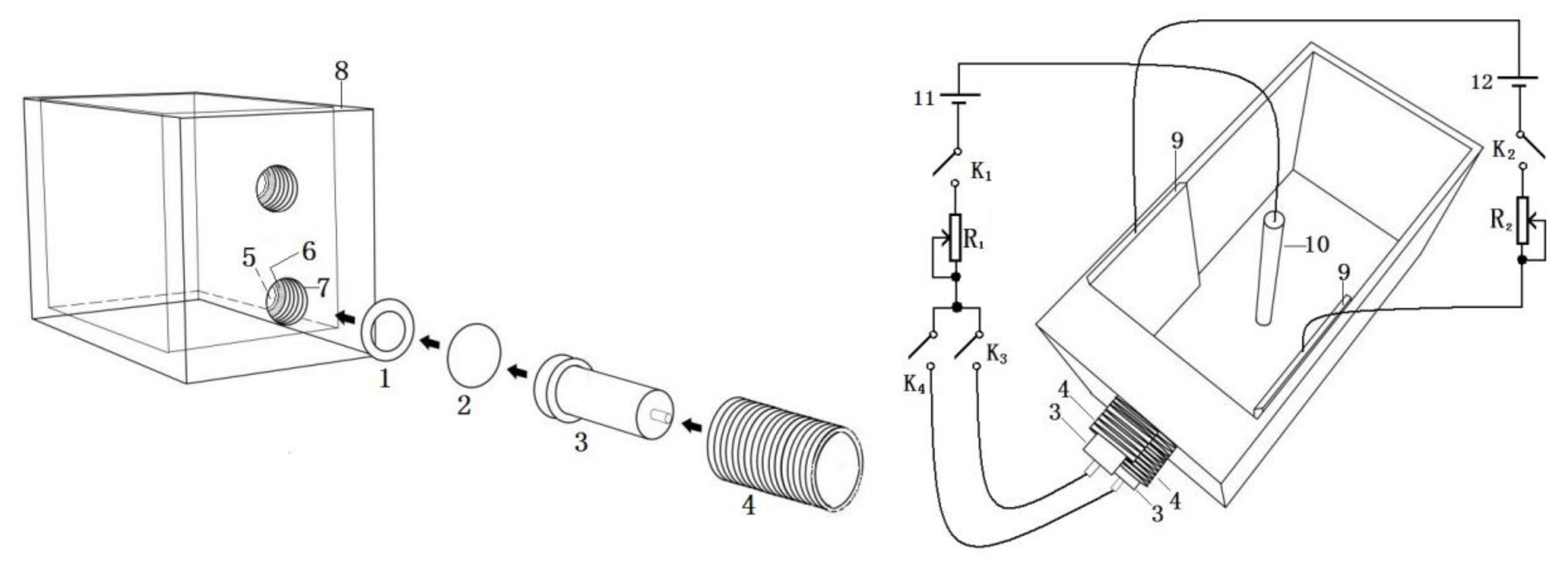
The experiments were carried out using a self-assembled double-working electrode electrolyzer. The experimental setup is shown in
Figure 1, which includes:
- 1.
Ring-shaped adhesive pad,
- 2.
Circular alumina foil,
- 3.
Reducer copper electrode,
- 4.
Inner fastening screw,
- 5.
Small cylindrical hole,
- 6.
Small cylindrical hole annular enclosure,
- 7.
Big cylindrical hole,
- 8.
Electrolyzer tank wall,
- 9.
Carbon sheet,
- 10.
Carbon rod,
- 11.
Deposition voltage source, and
- 12.
Deflection voltage source.
Two parallel carbon sheets were glued to the side walls of the electrolytic cell with epoxy resin as electrodes for the deflection field, so that the deflection field is perpendicular to the electrodeposition field, with a deflection voltage of 4–6 V. For illustration purposes, this paper specifies that the film is oriented in the direction of the positive potential of the deflection field towards the negative potential. In the
Figure 1 connection circuit, when K
1, K
3, and K
4 are closed and K
2 is open, we use the electrodeposition device without the deflecting electric field to prepare alumina-Co composite films with “twin” uniform structural coloration. When K
2 is closed, we can prepare alumina-Co composite films with “twin” gradient structural coloration in the deflection electric field assisted electrodeposition.
Alumina foil of 99.999% purity and 0.3 mm thickness was cut into 2 cm discs, flattened, then ultrasonically cleaned in acetone and alcohol for 30 min. The samples were rinsed repeatedly in deionized water, dried, and placed in a quartz tube furnace, vacuum annealed at 400 °C for 2 h. After cooling to room temperature, foil samples were electropolished in a mixture of perchloric acid and anhydrous ethanol (1:4 by volume) for 5 min. The polished alumina foil was washed with acetone and deionized water and dried. A 5 wt% phosphoric acid solution was prepared as the electrolyte, and two porous alumina oxide films with the same microstructure were obtained by electrochemical anodization at a temperature of 20 °C, oxidation voltage of 20 V, and oxidation time of 7–12 min. Alumina foil was used as the anode and the carbon rod as the cathode, while the electrode spacing was maintained at 10 cm.
To prepare the series of twin single structured alumina-Co composite films, two porous alumina films were used as the working electrodes, and carbon rod was employed as counter electrodes. For the electrolyte, a 0.12 mol/L CoSO
4 solution was used [
28]. Other parameters included an electrode spacing of 10 cm, deposition voltage of 12 V (root-mean-square), and the electrodeposition time of 5 s. In addition, a series of twin colorful gradient alumina-Co composite films were prepared by applying a deflecting electric field with an electrodeposition time of 30 s, keeping all other conditions constant.
The structural color of the alumina-Co composite films was characterized using a digital camera (EOS600D, Canon, Taiwan, China). The micro-zone morphology and crystal structure of the composite films were measured using a Scanning Electron Microscope (SEM)(S-4800, Hitachi, Tokyo, Japan) and an X-ray diffractometer (XRD, Cu-Kα) (SmartLab3000W, Rigaku Corporation, Tokyo, Japan). The visible reflectance spectra of the films were characterized using a UV–Visible spectrophotometer (U-3010, Hitachi, Tokyo, Japan), and the magnetism were obtained using a Physical Property Measurement System (PPMS-6000, Quantum Design, CA, USA). Comsol software was used to simulate the current density distribution of alumina-Co composite thin films.
3. Results and Discussion
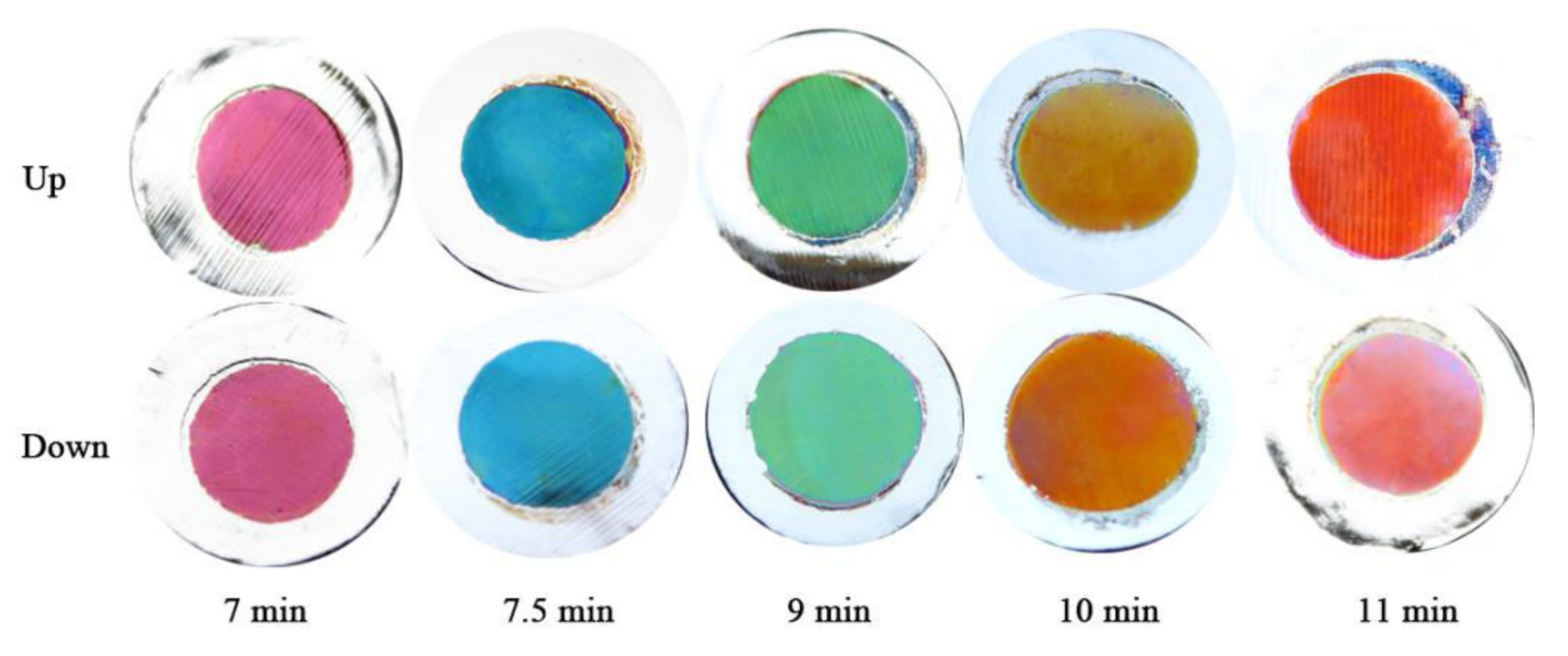
A series of twin alumina films were prepared under the below conditions: an oxidation voltage of 20 V, oxidation times of 7, 7.5, 9, 10, and 11 min as templates, a deposition voltage of 12 V, an electrode spacing of 10 cm, and an electrodeposition time of 5 s, without the application of a deflecting electric field. Digital images of the twin alumina-Co composite films are shown in
Figure 2. From the images, it can be seen that the composite films prepared under the same experimental conditions exhibit the same single structural color. On the one hand, this indicates that the Co particles were deposited in the same nanopores pattern in both alumina films, making the microstructure of the two composite films the same, so that the two composite films display the same structural color. On the other hand, it suggests that the Co particles were deposited uniformly, whereby different areas of the same composite film have the same microstructure and, thus, a single structural color. In addition, as the oxidation time of the alumina foil increased, the thickness of the porous alumina film increased, and the color of composite film changed from purple to blue to green to yellow to red due to the occurrence of interference.
According to the Maxwell Garnett principle and the multilayer thin film interference principle, calculation formulas are as follows:
where
nA,
nB,
dA,
dB,
θA, and
θB represent the effective refractive index, thickness, and incident angle of air-Al
2O
3 layer (A) and Co–Al
2O
3 layer (B), respectively;
m donates the interference level; and λ donates the interference wavelength of reflected light. The parameters of the composite films in the theoretical calculation are shown in
Table 1. It can be seen that the reflected light interference wavelengths under different oxidation times are 437, 468, 560, 621, and 683 nm, respectively. The corresponding visible light colors are very close to the structural colors displayed by the samples.
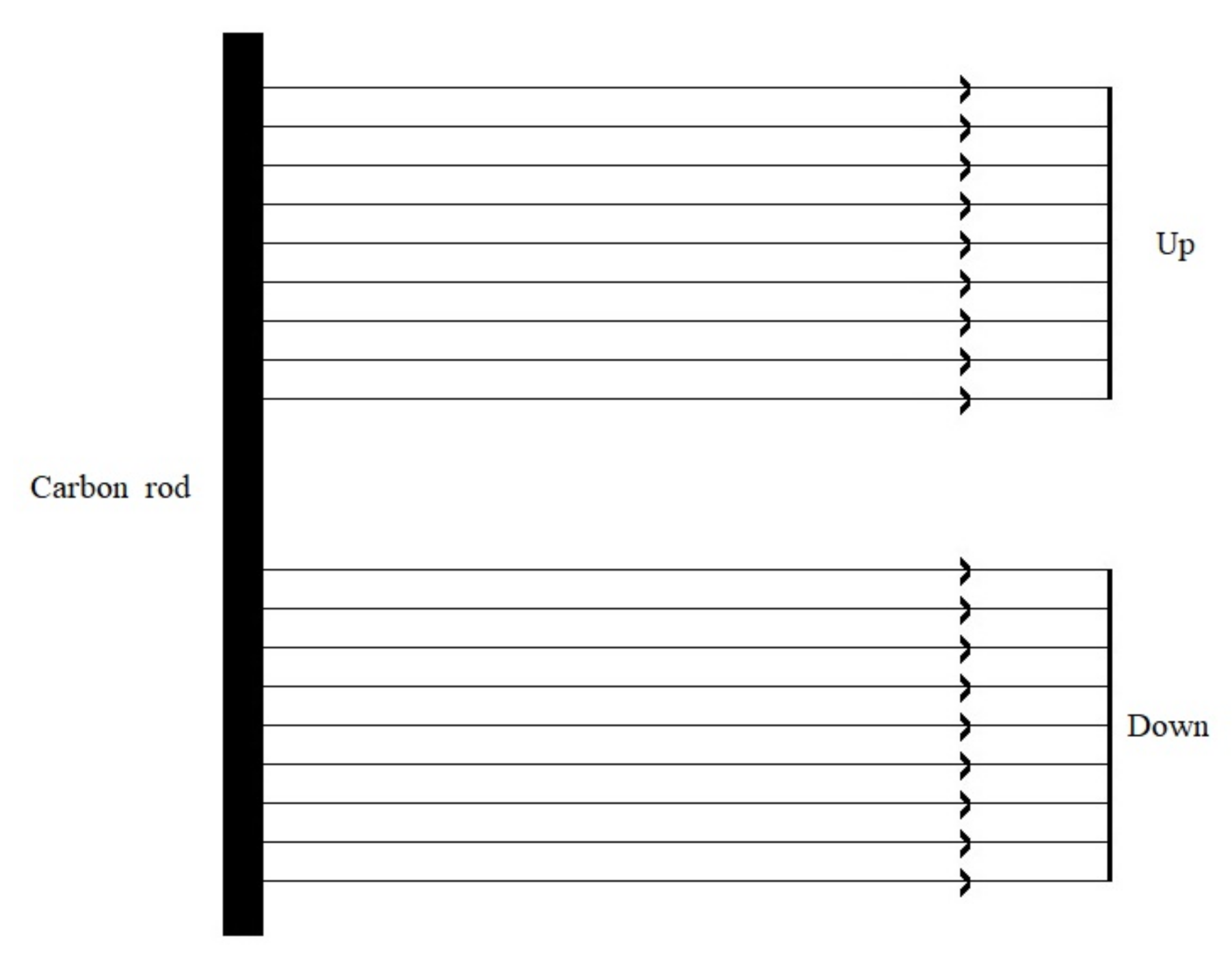
In the case of dual working electrodes, the upper and lower films showed a highly symmetrical structural color. Based on the experimental results, a model of the electrodeposition conductivity of the dual working electrodes was established, as shown in
Figure 3. In the case of distant electrodes, the deposition electric field between the porous alumina film and the carbon rod can be considered as a uniform electric field, and the deposition current was uniformly distributed on the surface of the upper and lower alumina films, resulting in two alumina films with the same microstructure and twin structural color. In addition, different areas of the same composite film displayed the same deposition current, which caused different areas of the composite film to have the same microstructure and, thus, a single structural color.
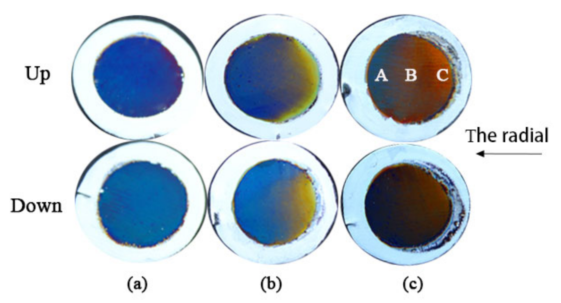
The twin alumina films prepared at an oxidation voltage of 20 V and an oxidation time of 12 min were used as templates. We prepared a series of twin alumina-Co composite films under the conditions of a deposition voltage of 12 V, electrode spacing of 10 cm, electrodeposition time of 30 s, to which we applied deflection voltage of 4, 5, and 6 V, respectively. The digital images of twin alumina-Co composite films are shown in
Figure 4, where a, b, and c correspond to deflection voltage of 4, 5, and 6 V, respectively. The structural color of the composite films prepared at the same deflection field is highly symmetrical. At a lower deflection voltage of 4 V, the composite film displays a single blue structural color, which transitions from yellow to blue in the radial direction when the deflection voltage was increased to 5 V. There is an obvious transition area between different structural colors.
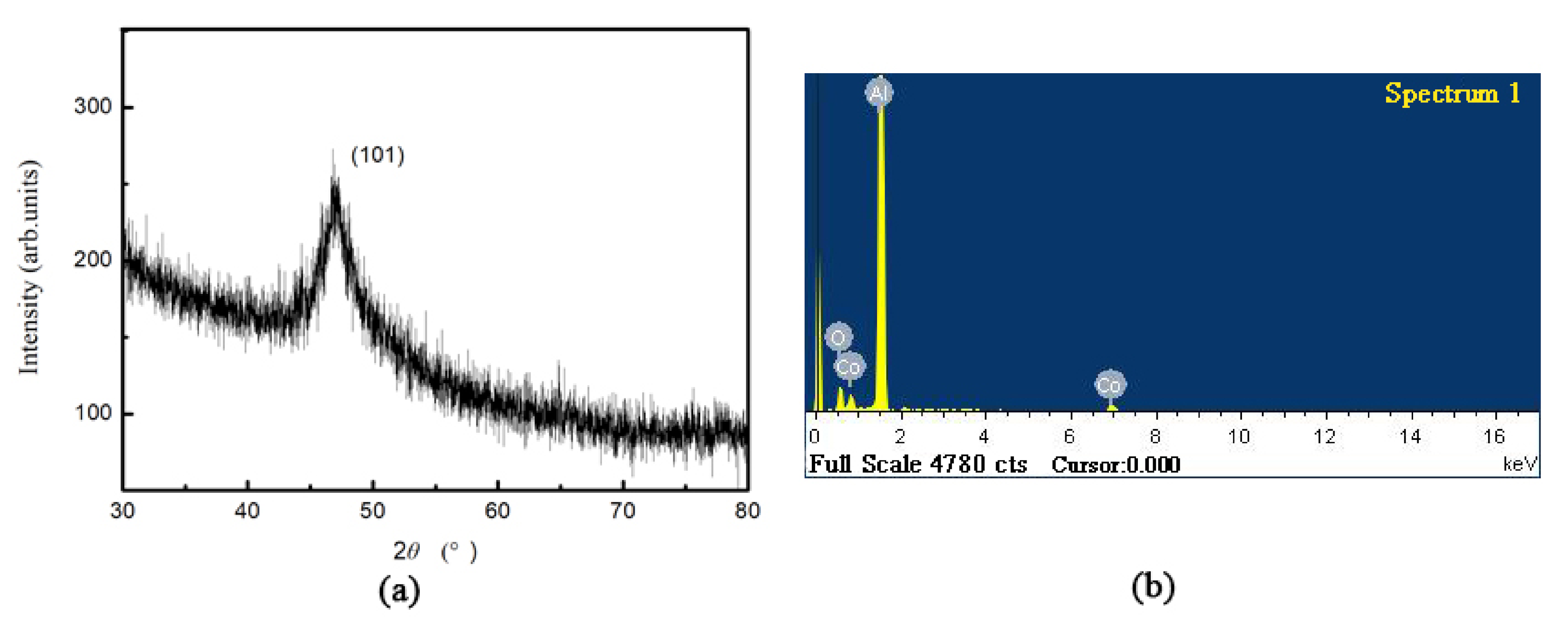
Figure 5 presents the XRD pattern and energy spectrum of the sample shown in
Figure 4c. The Co diffraction peaks of the hcp phase are observed in the spectrum of
Figure 5a, and Co is found to grow selectively in the (101) direction. The energy spectrum reveals the appearance of Al, Co, and O elements, where Al, and O are derived from the alumina film and Co indicates the successful deposition of metallic Co in the alumina film.
We further performed SEM characterization of different regions of the twin samples shown in
Figure 4c and found that the microstructures of the Up and Down samples are identical.
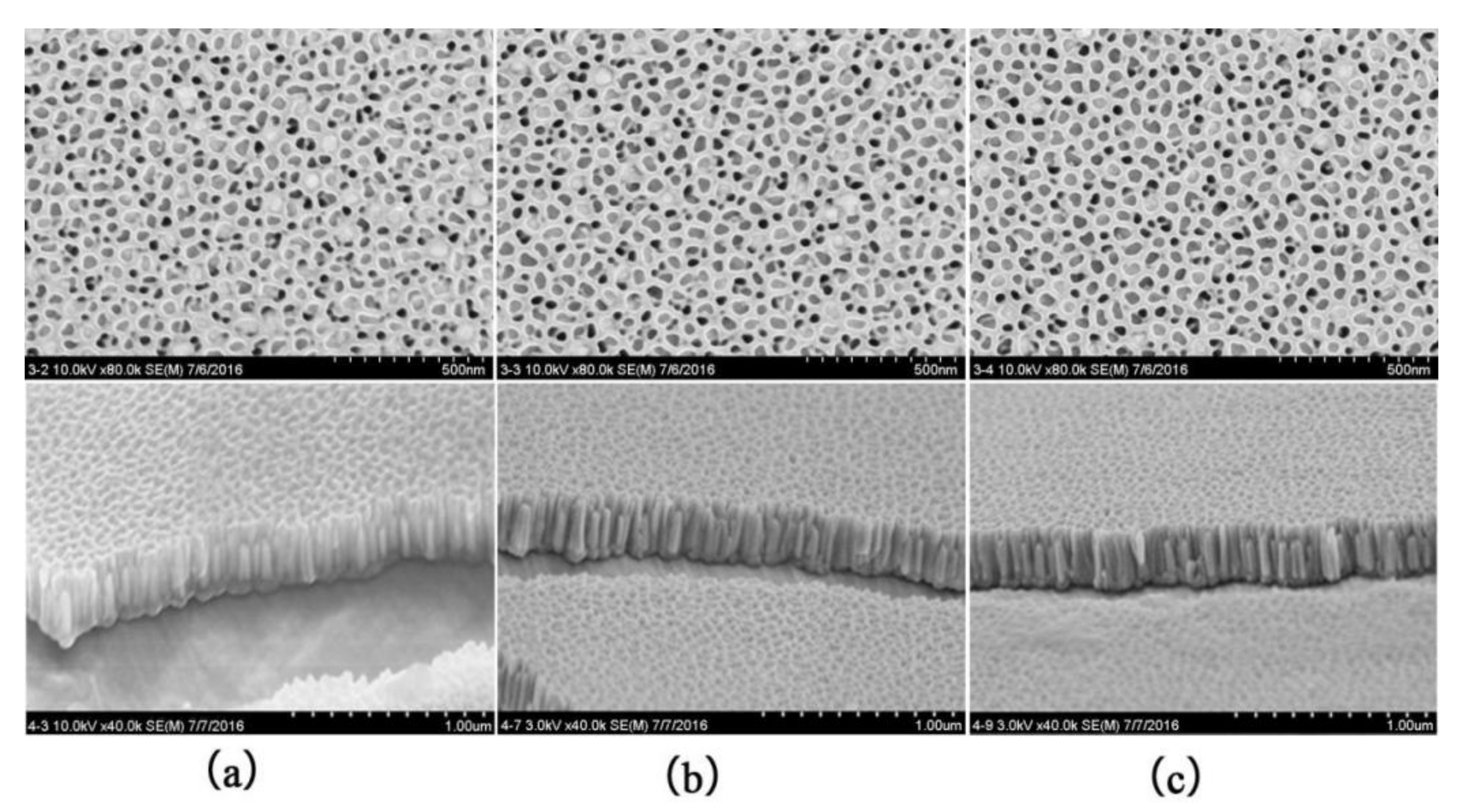
Figure 6 shows the SEM surface and cross-sectional images of the Up sample shown in
Figure 4c at different locations, where a, b, and c correspond to regions A, B, and C, respectively. From the images, it can be seen that Co nanowires were distributed in nanopores in different regions of the alumina, and the Co nanowires density distribution gradually increased along the radial direction (region C to A.) The Co nanowires grew in the alumina pores under the deposition electric field and sealed the pore openings when they expanded to the pore surface. It can also be observed from the surface images that most of the pore openings were blocked in region A, but not so much in region C, which indicates that the density of Co nanowires in A is greater than that in C. During the electrodeposition process, the concentration distribution of Co ions gradually increased from region C to A due to the effect of the deflecting electric field. Under the deposition electric field, a large number of Co ions entered the nanopores in region A of alumina and grew into Co nanowires with higher density. In region C, the concentration of Co ions remained relatively small, and thus the density of Co nanowires was smaller. Due to the same deposition electric field, the lengths of Co nanowires in regions A, B, and C were approximately the same at about 220 nm.
The electron microscope images show that the microstructure of the composite film exhibits irregular changes along the radial direction. In order to study the mechanism and change law of the film structural color generation, we established a structural model of the microregion of the composite film, considering that the diameter and hole spacing of the nano-pores of the alumina film are much smaller than the visible wavelength. To facilitate the calculation, the structural model was simplified to an equivalent structural model using the electron microscope characterization parameters and porosity, as shown in
Figure 7. According to Equation (1), the parameters of the composite films obtained from the theoretical calculation of the equivalent structure model are shown in
Table 2. It can be seen that the reflected light interference wavelengths in regions A, B, and C of the composite films are 464, 459, and 753 nm, respectively. The corresponding visible light colors are very close to the structural colors displayed by the samples. This finding suggests that it is reasonable to use the structural equivalent model to analyze the multilayer film interference under the condition that the diameter and hole spacing of the nanopores of the alumina films are much smaller than the visible light wavelengths.
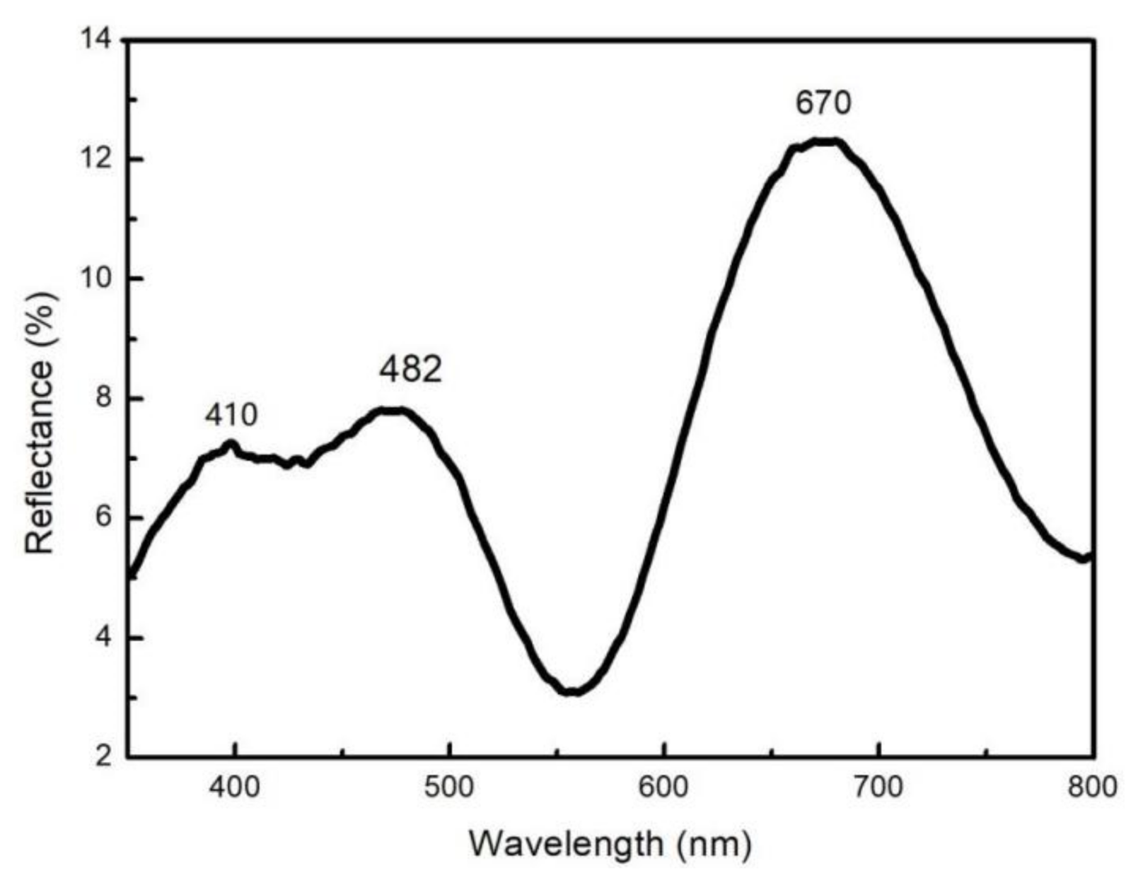
In addition, we conducted a spectral test on the Up sample in
Figure 4c, and the results are shown in
Figure 8. It can be observed from the figure that the reflection peaks at 410, 482 and 670nm are in the violet range, blue range, and red range of the visible spectrum, respectively, which slightly deviate from the observed color of the experimental samples. Since the microstructure, medium thickness, and refractive index of the alumina-Co composite film exhibit continuous gradient changes along the radial direction, the interference wavelength of the reflected light is the superposition of different wavelengths from a similar micro-region. In addition, the light range difference in the superposed light changed gradually along the radial direction, resulting in the gradual variation in the structural color of the film and the slight difference between the structural color observed from the macroscopic view and the spectrum. The alumina-Co composite films produced a gradually changing microstructure rather than a mutational one. Therefore, the interference wavelength of reflected light was little changed in a certain microscopic region, which resulted in a broader reflection peak rather than a narrower one.
For the sample shown in
Figure 4, when the deflection field was small, the effect of Co ions subjected by the deposited electric field was significant, and the difference in Co nanowire density distribution in different areas of the same film was small. Accordingly, the microstructure of the film changed less along the radial direction, and the structural color tended to be a single color. With the increase in the deflection electric field, the gradient of the Co nanowires density along the radial distribution increased, which caused the gradient of the light range difference between the upper and lower surfaces of the adjacent areas of the film to increase. When the light range difference changed beyond a certain wavelength coverage, multiple colored stripes appeared due to interference.
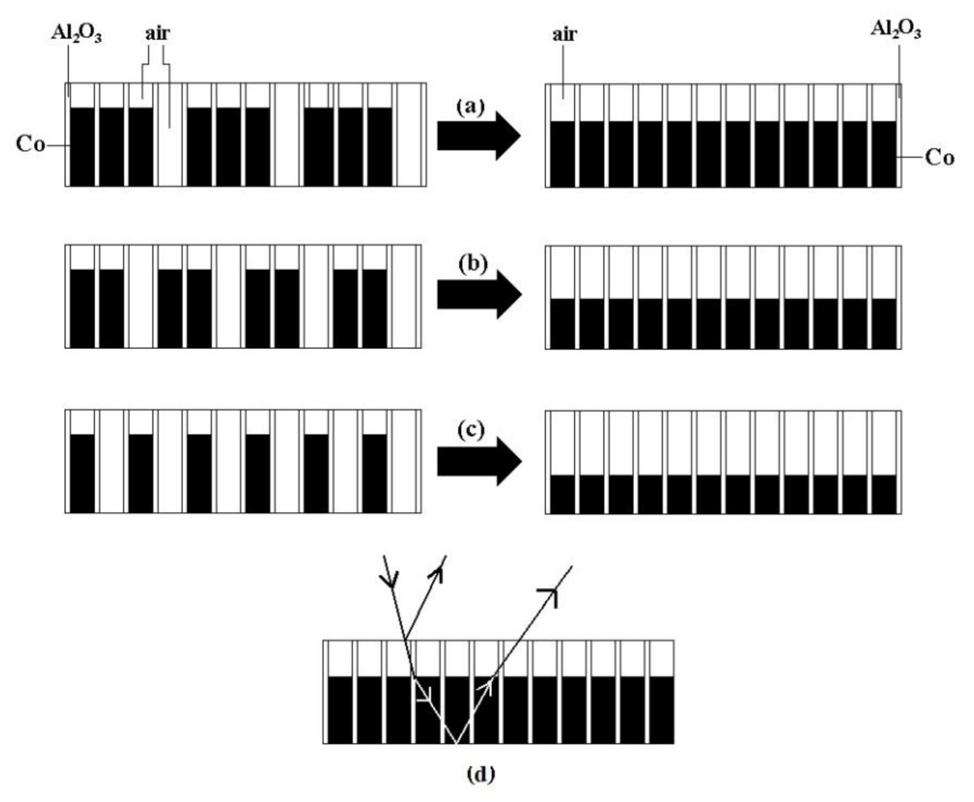
To prepare metal nanowires using nanopores of alumina thin films, the conventional method was used to remove the alumina barrier layer so that the alumina nanopores were permeable at the top and bottom, and to deposit a layer of electroconductive film as an electrode on one side of the alumina film by the magnetron sputtering or vapor deposition process, obtaining metal nanowires by the direct current (DC) electrodeposition process. In this paper, we used an AC electrodeposition process to deposit Co particles in the nanopores of the film using the single-phase conductivity of the porous alumina film [
23]. During the deposition process, the distribution of the deposited electric field in regions A, B, and C along the direction parallel to the nanopores was the same. Each nanopore acted as a conducting branch, so that the length of the nanowires formed at the bottom of the pores in different regions was essentially the same. Since the deflected electric field is perpendicular to the deposited electric field, the Co ion concentration gradually increased along the radial direction. As a result, the number of nanowires formed in the nanopores of the film in region A was higher, the nanowire density was larger, and the density of Co nanowires in region C was smaller under the action of the same deposited electric field. Porosity
f was calculated using the following equation:
where
r is the hole radius of
21 nm;
Dint is the hole spacing of 76 nm; and the calculated porosity
f is 0.277. The calculated folded thickness
h (
h = average length of Co nanowires × porosity) of Co deposited in regions A, B, and C was 58, 46, and 25 nm, respectively. Faraday’s law was used for the deposition of metal ions on the cathode surface:
where
h is the folded thickness of Co;
n is the atomic valence of the deposited element of 2;
ρ is the density of the deposited element (8.9 g/cm
3);
M is the relative atomic weight of the deposited element of 59; and
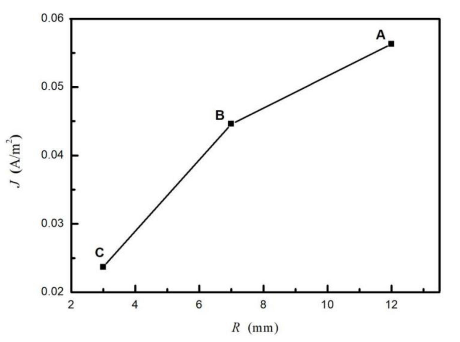
t is the deposition time of 30 s. The deposition current density variation curves for regions A, B and C are shown in
Figure 9, where the horizontal coordinate is the length of the film diameter along the radial direction. The diameter of the alumina film in this experiment was about 14 mm. The obtained curve reveals that the deposition current density gradually increased from 0.024 A/m
2 in region C to 0.056 A/m
2 in region A.
To further discuss the microscopic essence of the increase in deposition current density along the radial direction, the following equation based on the current density distribution law and absolute velocity of the reduction reaction was used:
where
F is Faraday’s constant;
k is the front factor;
C is the concentration of Co ions on the electrode surface;
α is the transfer coefficient;
R is the Boltzmann constant;
φ is the equilibrium potential; and Δ
φ is the polarization value of the electrode when current is passed though. In the electrodeposition process, the liquid phase mass transfer step is in quasi-equilibrium, while the front factor
k, transfer coefficient
α, equilibrium potential
φ, and polarization value Δ
φ of the electrode are the same in the liquid layer near the electrode surface. According to Equation (4), the deposition current density
j gradually increases in the direction of the deflected electric field, which can only be caused by the gradually increasing concentration of Co ions on the electrode surface along the direction of the deflected electric field. This confirms the above experimental results from another perspective.
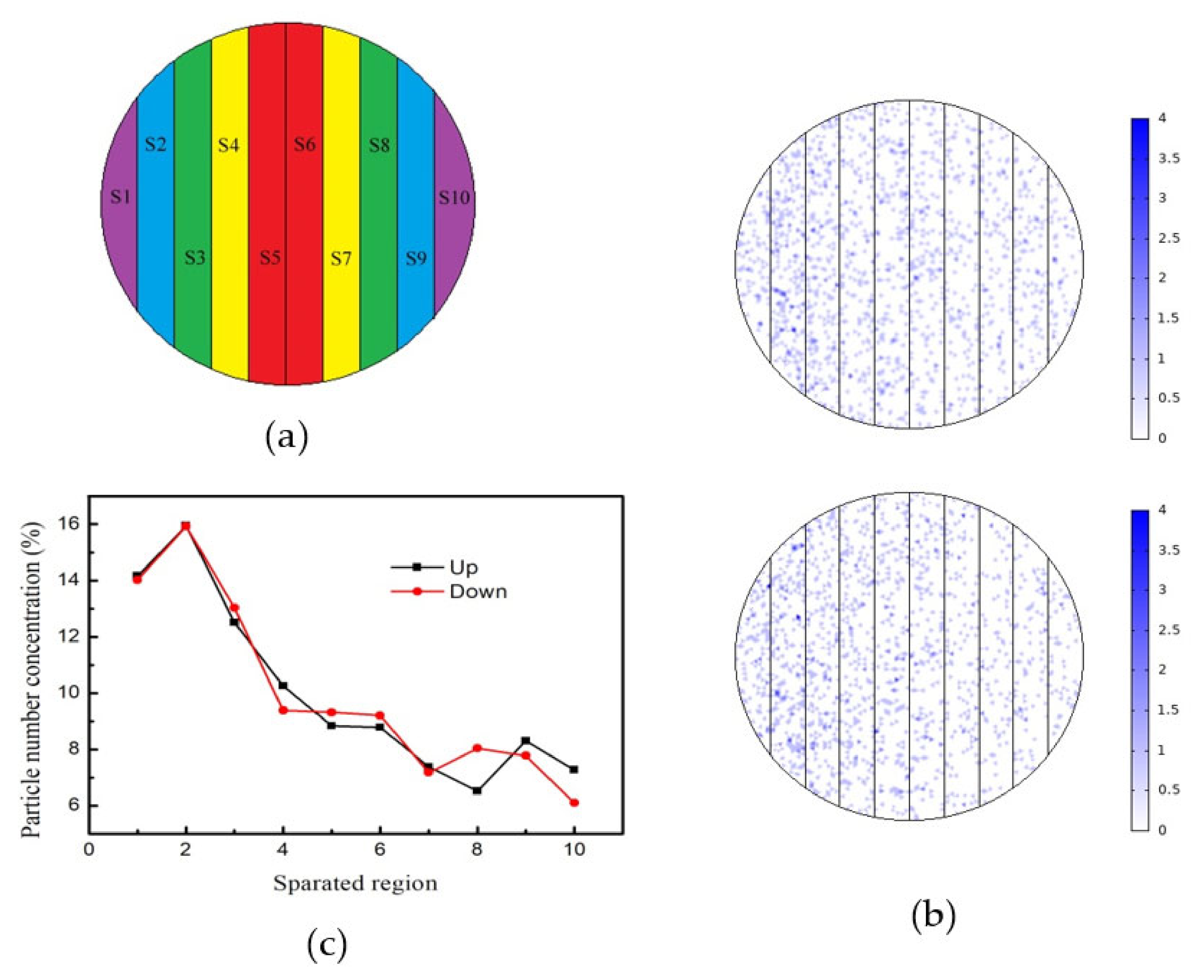
In order to quantitatively study the deposition pattern of Co particles under the deflected electric field, we performed tracking simulation of Co particles using software. The porous alumina film was divided into 10 regions along the radial direction, as shown in
Figure 10a. In the zero-moment space, 10,000 Co particles were uniformly released, and then were reflected after impacting with the boundary particles other than those of the alumina sheet in the container. As a result, the two twin alumina films adhered after the impact of the particles. The transient simulation step took 10
−7 s, and the simulation time was 10
−5 s. The simulation results of Co particle deposition on the surface of the two twin alumina films at the end of 10
−5 s are shown in
Figure 10b, where the chromaticity bar displays the number of particles. White means zero particles, and pure blue indicates four particles. The number of particles in each region of the twin alumina film were counted, and the number of particles in different regions is shown in
Table 3. In order to facilitate a quantitative analysis, we normalized the number of particles in each region and obtained the deposition rate per unit area versus position curve, as shown in
Figure 10c. From the curves, we can see that the deposition rate per unit area of the two films varies approximately in the same pattern. In this simulation experiment, we divided the samples of the twin films into 10 regions and calculated the average value of the uniformly released microscopic particles on the sample surface at zero time. Due to the phenomenon of particle fluctuation and Brownian motion, the particle number concentration in the same region of the twin films had a slight deviation, especially for regions 8 and 10 as shown in
Figure 10c. Due to the limitations in the selection of conditions, such as the number of particles and action time of the deflecting electric field in the particle tracking simulation, a numerical difference was observed between the simulated Co particle deposition rate and the deposition current density shown in
Figure 9. However, the variation law of deposition rate and current density along the radial direction of the film is the same.
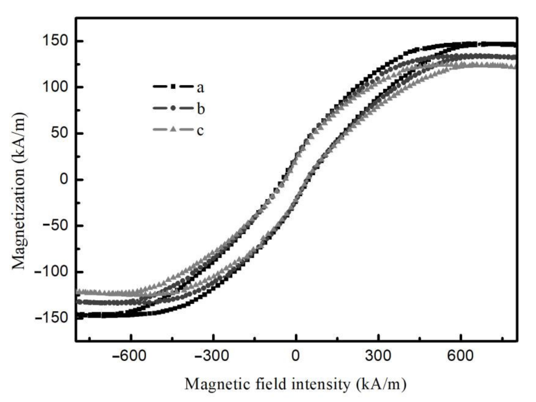
Figure 11 illustrates the hysteresis loops of different regions of the composite film shown in
Figure 4c at room temperature with the applied magnetic field perpendicular to the film surface. It is apparent that the different regions of the composite film exhibit ferromagnetic properties, and the saturation magnetization intensity increases gradually along the radial direction with 118, 130, and 150 kA/m, respectively. These findings confirm that the magnetic magnitude of the microregion of the film can be regulated by the applied deflected electric field.


