Article

Cold Spray Additive Manufacturing of Ti6Al4V: Special Nozzle Design Using Numerical Simulation and Experimental Validation

1
Key Laboratory of Solidification Processing, School of Materials Science and Engineering, Northwestern Polytechnical University, Xi’an 710072, China
2
Shaanxi Key Laboratory of Friction Welding Technologies, School of Materials Science and Engineering, Northwestern Polytechnical University, Xi’an 710072, China
*
Authors to whom correspondence should be addressed.
Coatings 2022, 12(2), 210; https://doi.org/10.3390/coatings12020210
Submission received: 13 December 2021 / Revised: 18 January 2022 / Accepted: 19 January 2022 / Published: 6 February 2022
(This article belongs to the Special Issue Cold Spray Additive Manufacturing)

Abstract

:
Cold spray additive manufacturing (CSAM) shows great potential in titanium-alloy production as it is a solid-state process. However, data published so far have demonstrated the difficulty of producing dense and high-strength Ti alloy parts. Our previous studies have shown that nozzle design together with high-cost helium propulsive gas plays a crucial role in particle acceleration. In this work, special nozzles for Ti alloy were designed and validated experimentally with commercially available Ti6Al4V powder. Simulation results show that particle impact temperature increases remarkably for a long convergent length, while particle kinetic energy slightly increases, which is validated by experiments. The relationship between the particle impact temperature and practice diameter shows the first increase and then decrease. The experimental results show that as the nozzle convergent section becomes longer, the edges of the single-pass deposits become smoother, and the width, density, deposition efficiency, and microhardness of the single-pass deposits increase.

1. Introduction

Cold spray additive manufacturing (CSAM) [1,2], which has developed from the cold spray (CS) coating process, is a new member of the additive manufacturing technologies [3,4]. It is based on the solid-state deposition of severely deformed powder particles that impact a substrate at high speeds to form a deposit. It differs from conventional thermal spraying, as it is achieved at much lower temperatures and higher impact velocities [5,6]. Temperatures are usually far below the melting point of the spraying powders, which allows for oxide-free deposits with a negligible heating effect on the spray materials and substrates. Residual stresses in these deposits are of the compressive type, which is beneficial in fabricating thick deposits [6,7]. A large number of materials have been successfully deposited, such as Cu and its alloys [8,9,10], Al and its alloys [11,12,13], metal–metal composites [4,14,15,16], metal–ceramic composites [17,18,19,20], Inconel 718 [21,22,23], Ti [24] and Ti6Al4V [25,26,27]. However, over the years, it has remained very difficult to produce high-strength Ti6Al4V deposits [28,29], although in situ shot peening assisting cold spray [30] or post-treatment with heat treatment and thermostatic isostatic pressure [6,9,31,32] can improve their densities.
According to the literature [6], the increase in velocity of titanium alloy particles allows for the fabrication of a relatively dense deposit. It has been demonstrated that to achieve a high particle velocity, especially designed Laval nozzles with a convergent section and a divergent section are necessary for a CSAM system. The internal dimensions of the Laval nozzle affect the particle acceleration [33]. A lot of relevant works have been performed, as shown in Table 1 [34,35,36,37,38,39,40,41,42,43,44]. Most of the published studies focus on the optimization of the nozzle expansion ratio (the ratio of exit to throat cross-sectional area) [34,35,36,37] and divergent length [34,36,37,38]. Some researchers have used high-pressure cold spray systems to prepare pure titanium coatings to protect magnesium alloys [45]. In addition, some scholars have studied the effect of nozzle transverse speed [6,25] and standoff distance [46] on Ti coating structure. The divergent section mainly affects the acceleration of the particles. Fewer studies have focused on the effect of convergent length [39] on Al powders. Micronozzles for energy-efficient spraying have been investigated with Al and Ti powders [40,41,42]. Single Ti particle impact behavior has been investigated in the deposition of Ti [43]. The effect of convergent length has been studied, and single-pass Ti coatings have been produced for different nozzles [44]. Among the possible process parameters, particle velocity and deposition efficiency have been studied.
Various metal materials, such as Cu, Al, Ti, and Ti6Al4V, have widely divergent properties, as shown in Table 2 [47,48,49]. Hence, the critical velocities of Cu, Al, Ti, and Ti6Al4V for CSAM are very different from 451 m/s to 1013 m/s at room temperature (20 °C) [47,49]. The Laval nozzles commonly employed to produce deposits of Cu, Al, and their alloys have a short convergent length (range of 5–57 mm in Table 1). Titanium and its alloys have much lower thermal conductivities and higher yield strengths compared to Cu and Al, which is not conducive to heat transfer in powder particles.
Therefore, it is necessary to investigate nozzle geometries for titanium alloy particles. The quality of the deposit is dependent on several variables of the inflight particle when it impacts on the substrate, particle velocity, and temperature. In [34], a long convergent section together with a fixed nozzle divergent section was found to be beneficial to the temperature of titanium alloy particles. Titanium alloy particles may undergo severe plastic deformation at high velocity and temperature during CSAM. The synergetic effects of high velocity and temperature allow for good mechanical interlocking and metallurgical bonding at the interface, which improves the density and mechanical properties. The majority of published works have not studied the effect of the powder carrier gas with numerical modeling. It is known that the introduction of powder carrier gas at room temperature adversely affects the acceleration and temperature of particles [50]. Therefore, the powder carrier gas was also investigated in this study.

2. Numerical Modeling and Experimental Methodology

2.1. Numerical Model

The numerical model for the nozzle incorporates the powder injection, the nozzle internal structure, and the substrate, as shown in Figure 1. The propulsive gas enters the convergent section (convergent length, Lc) from the inlet (inlet diameter, Di). The gas together with the powder flies through the powder injection to the convergent section. Heat is exchanged between room-temperature particles and the carrier gas as well as the high-temperature gas in the convergent section. Later, as they pass through the throat (throat diameter, Dt), follow the divergent section (divergent length, Ld), and exit (exit diameter, De), the Ti6Al4V particles are heated and accelerated in the nozzle and impact on the substrate to produce the deposit. The outer diameter (D) of the powder injection pipe is 4 mm and its inside diameter is 2 mm. The substrate is a disc with a thickness of 5 mm and a diameter of 40 mm, while the standoff distance (SoD) between the nozzle and the substrate is 30 mm.
The different nozzle dimensions studied are shown in Table 3. As the throat diameter affects gas consumption, considering the supply capacity of the gas source, two different nozzle sizes, one for low gas consumption (Dt = 1.5 mm) and another one representing standard size (Dt = 2.7 mm), were studied. In our previous studies, the nozzle was optimally designed by coupling inside dimensions and gas flow so that the particles travel to reach an adequate acceleration [34,35]. Based on these findings, the optimized nozzle inlet diameter (Di = 20 mm), suitable expansion ratio, and long divergent section were selected for this study. The small-throat-diameter nozzles were of two types, the first one, named 1.5–30, had a convergent length of 30 mm, and the second one, named 1.5–65, had a convergent length of 65 mm. The Ld and De were 170 and 3.6 mm, respectively. The large throat diameter nozzles were of three types, named 2.7–30 (Lc = 30 mm), 2.7–40 (Lc = 40 mm), and 2.7–90 (Lc = 90 mm). The Ld and De were 210 mm and 6 mm, respectively. Nitrogen (N2) was used as the powder carrier gas as well as the propulsive gas. The propulsive gas pressure and temperature were 3 MPa and 550 °C, respectively.
The numerical analysis suite FLUENT 15.6 was employed for the simulations to calculate the flow field around the nozzle using a two-dimensional axisymmetric model, which was chosen to reduce computational load [35]. According to the aforementioned model structure, the calculation area was divided into three parts: contraction section, expansion section, and outer area. A mesh of quadrilateral elements was used. Both the nozzle wall and the substrate were set as non-slip boundaries, and the thermal condition was set as adiabatic. The powder particles were fed from the center of the nozzle entrance, and the sizes of the corresponding particles were set according to different research focuses. The particles were all set as spherical particles, the initial speed was set to 15 m/s, and the initial temperature was set to 300 K. In the solution process, a density-based coupled solver and a second-order upwind discrete scheme were used, and the steady-state solution was used as the result. Additionally, the effect of particles on the flow field was ignored in the solution process. The other model parameters and details have been described in previous studies [36].

2.2. Experiment Materials and Method

The spray powder used was commercially available Ti6Al4V powder prepared by inert gas atomization. The particle morphology and size distribution are shown in Figure 2. Ti6Al4V particles are spherical, with an average diameter of 25 μm. Furthermore, the test uses ten Ti6Al4V plates of the same size as the substrate, with each plate being 50 mm long, 50 mm wide, and 2 mm thick. Half an hour before the CSAM experiment, the substrates were sandblasted using Al2O3 powder to remove oxides and impurities on the surface.
The five different nozzles and deposits made by the 2.7–90 nozzle are shown in Figure 3. Stainless steel 304 (Northwest Nonferrous Metals Research Institute, Xi’an, China) was selected as the metal material and the nozzles were prepared by mechanical processing. The internal sizes of five different nozzles were machined according to the dimensions listed in Table 3, and the appearance of the five different nozzles is shown in Figure 3a. The Ti6Al4V deposits were produced using a custom-developed high-pressure CSAM system; the nozzle was as shown in Figure 3b. The parameters selected were the same as those used in the simulations. The powder feeding rate was 3 rpm, and the nozzle travel speed was 40 mm/s. The single-pass deposits fabricated by 2.7–90 nozzle are shown in Figure 3c. The microstructure of the deposits was studied with the TESCAN tungsten filament scanning electron microscope (Brno, Czech Republic), while samples were prepared by grinding and polishing to measure their width and thickness. The THV-1D Vickers hardness tester (TIME, Beijing, China), was used to test the microhardness of the coatings. Five points were tested for each coating, and the average value was taken as the microhardness of the coating.

3. Results and Discussion

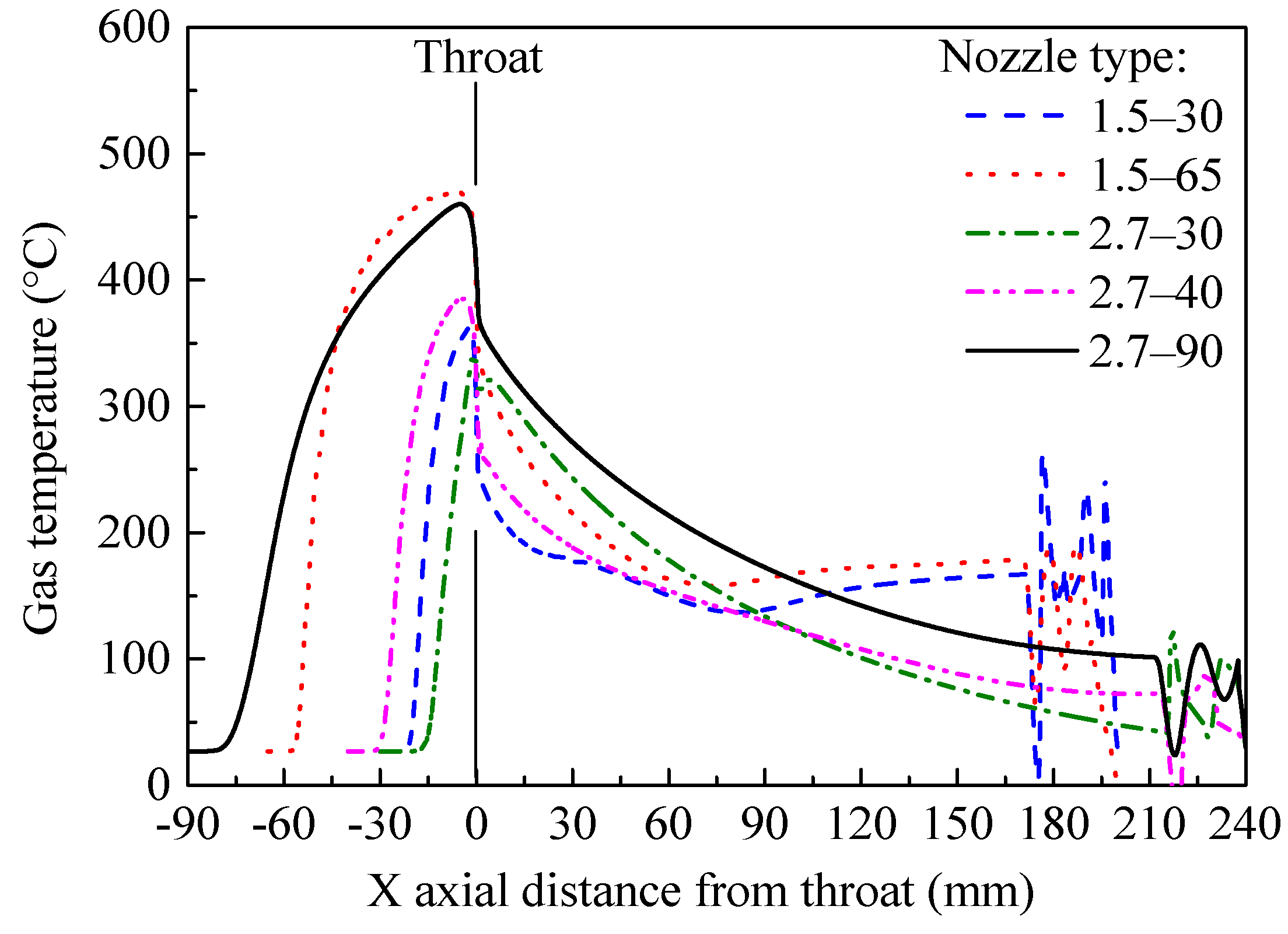
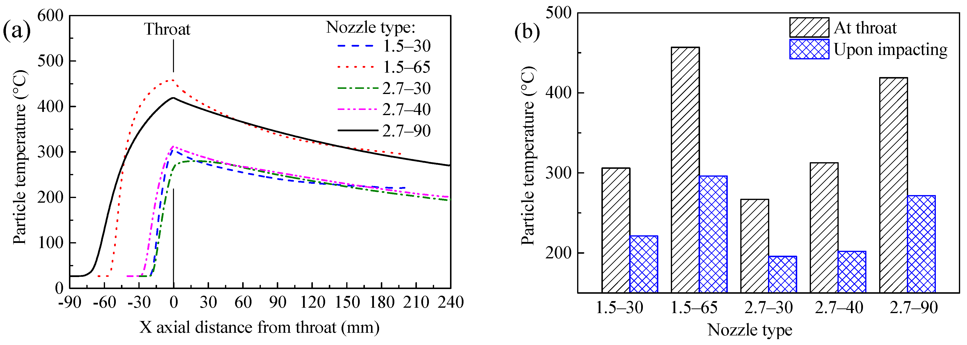
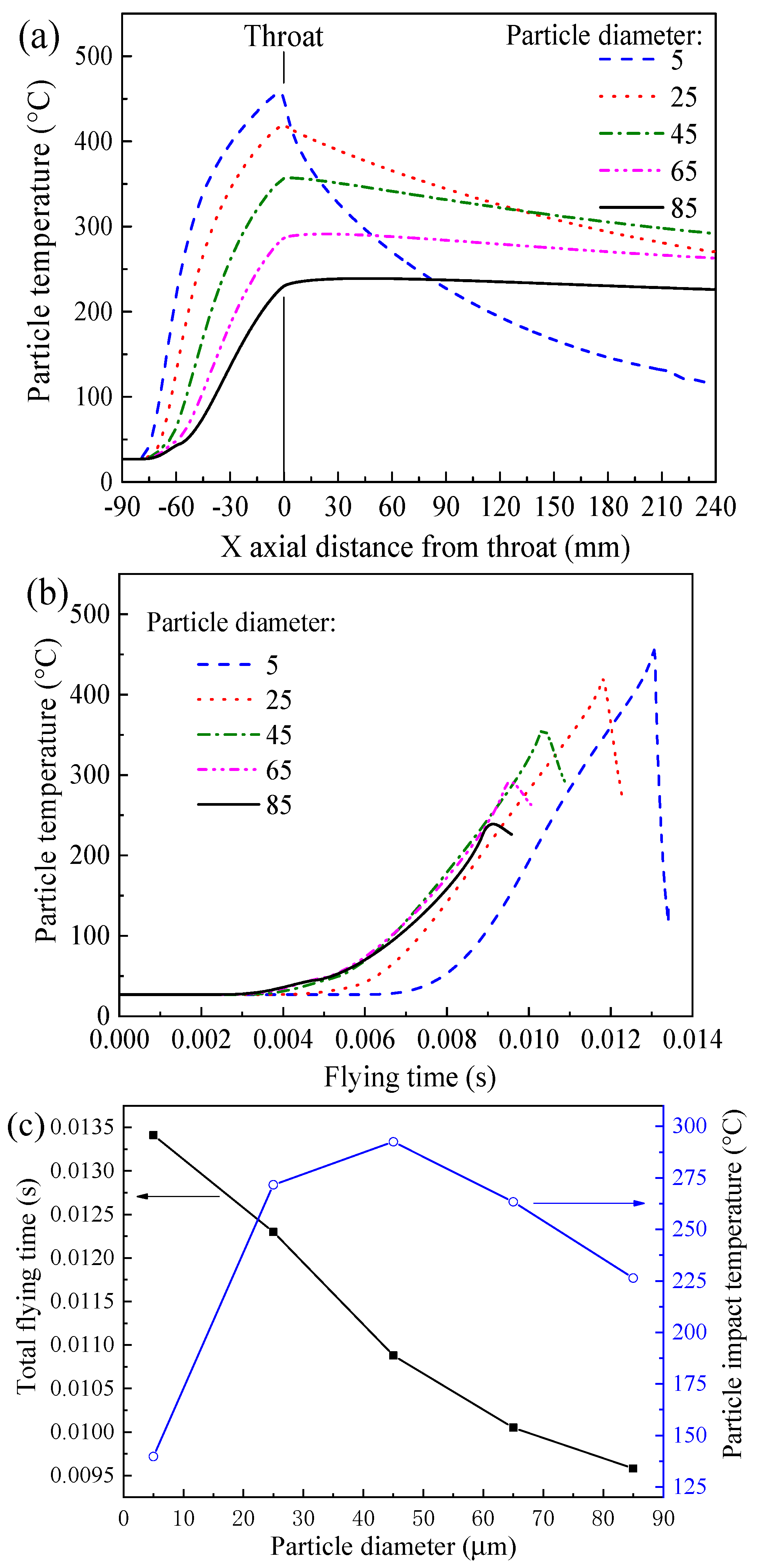
3.1. Gas Flow, Gas Temperature, and Particle Temperature

The gas temperature distribution in the nozzle convergent section for various convergent lengths is shown in Figure 4. The powder carrier gas is introduced at room temperature and remains in the center of the nozzle, while the high-temperature propulsive gas fills the rest of the nozzle volume. Those flows begin to mix at about 5 mm inside the inlet. As the convergent section becomes long, the temperature of axial gas rises, and the gas flow becomes evenly distributed.
The gas temperature along the nozzle axis was calculated as shown in Figure 5. It increases significantly in the convergent section reaching a maximum close to the throat. This causes the gas to expand and decreases its temperature in the divergent section. When keeping the throat diameter constant, axial gas temperature increases with convergent length, as the mixed gas shows an improved exchange of heat. This would be beneficial for the temperature of the particle.
Particle temperatures under different nozzle conditions are shown in Figure 6. As can be seen in Figure 6a, it rises rapidly soon after powder injection, reaches a maximum at the throat, and then decreases gradually over the divergent section. When the convergent length is long, the particle temperature at the nozzle throat increases, as shown in Figure 6b. The particle impact temperature increases from 221.3 to 296.1 °C when the convergent length increases from 30 to 65 mm for the 1.5 mm throat. The particle impact temperature increases from 195.7 to 271.6 °C when the nozzle convergent section changes from 30 to 90 mm for the 2.7 mm throat. Particles at high temperatures are more likely to become soft and plastically deform during CSAM.
In our previous studies [35,50], we showed that particle size affects particle acceleration. The calculated particle temperatures of different-sized particles upon impact on the substrate are shown in Figure 7. The impact temperature of the 5 μm particle is the lowest among the three sizes of particles for the same nozzle. In addition, when the nozzle throat is 1.5 mm, the impact temperature of the 45 μm particle increases from 196.6 °C to 331.5 °C with an increase in convergent length from 30 mm to 65 mm. When the nozzle throat is 2.7 mm, the impact temperature of the 45 μm particle rises from 176.5 °C to 292.5 °C with an increase in convergent length from 30 mm to 90 mm. It should be noted that when the convergent length is shorter (either 40 mm or 30 mm, as in the 1.5–30 case, the 2.7–30 case, and the 2.7–40 case), the impact temperature of the 25 μm particle is the highest. This may indicate that the relationship between particle temperature and particle diameter first increases and then decreases.
To analyze and verify this interesting relationship, a wide range of particle diameters was used, from 5 to 85 μm, with an increment of 20 μm, in the case of the 2.7–90 nozzle. The particle temperatures along with the nozzle axis and the flying time are shown in Figure 8a,b, respectively. Similar to Figure 6a, the particle temperature firstly increases and then decreases with the maximum at the nozzle throat for all particle diameters. increased particle diameter, steeper temperature rise in the convergent section, and drastic drop in the divergent sections can be observed (Figure 8a). The 5 μm particle yields the longest time in the nozzle, while the 85 μm particle yields the shortest time, as indicated in Figure 8b,c. Meanwhile, the 45 μm particle shows the highest impact temperature, as shown in Figure 8c. This result could be caused by the different acceleration behaviors of different particles in both the convergent and divergent parts of the nozzle. Hence, to have the highest possible impact temperature of a given powder (having a certain particle size distribution), a suitable nozzle convergent section is necessary.

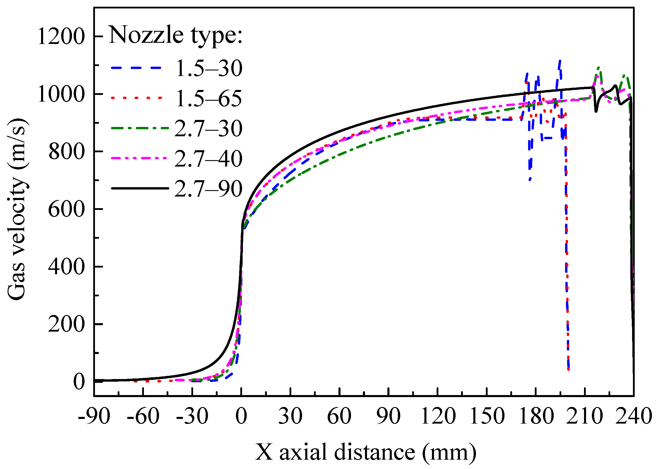
3.2. Gas Velocity and Particle Acceleration

The gas velocity along the nozzle axis is shown in Figure 9. As the gas flows through the throat, it accelerates significantly in the divergent section. When the length of the convergent section increases, the gas velocity becomes slightly higher. The calculated particle kinetic energy along the nozzle axis for various nozzles is shown in Figure 10. The increase in the particle kinetic energy effect is similar to that of gas. In previous studies, particle acceleration has been found to be dependent on the divergent length, with particles having a higher velocity with longer divergent sections [36]. The particle kinetic energy increases when the length of the convergent section increases in this study. This is a new finding, suggesting that the convergent section also has some beneficial influence on particle acceleration.
The kinetic energies of particles with various diameters upon impact on the substrate are shown in Figure 11. It can be seen that for the three particle sizes studied in this work, the particle kinetic energy before impact increases slightly with increasing convergent length, while the 45 μm particle reaches higher kinetic energy than the 25 μm and 5 μm particles. Particles with higher kinetic energy deform plastically in a more extensive manner.

3.3. Microstructure of Single-Pass CSAMed Ti6Al4V Deposit

The five different single-pass deposits and their widths are shown in Figure 12. The deposit in the 1.5–30 case in Figure 12a is about 4 mm in width with rough edges; as the convergent length increases from 30 to 65 mm, the width increases a little, from 4.1 to 4.5 mm, and the roughness of the edges is reduced, as shown in Figure 12b. When the nozzle throat diameter is 2.7 mm, the convergent length increases from 30 to 90 mm, as shown in Figure 12c–e; the width of the single-pass deposit also increases from 8.2 to 8.9 mm, the edges of the deposit change from rough to smooth, and the particle distribution on the single coating surface is relatively uniform. It can be concluded from Figure 12f that as the length of the nozzle convergent section increases, the width of the deposit increases.
The cross-sectional microstructure of the single-pass deposit is shown in Figure 13. The deposits with an arched shape are on the substrate, and the deposit and corresponding substrate are well combined. The deposits in the 1.5–30 cases are loose, with many tiny pores. In contrast, the thickness of the deposit in the 1.5–65 case increases, the zone of the deposit close to the substrate is dense, and its upper zone is relatively loose, which is because of the “tamping effect” in the CSAM process [51], as the following particles further tamp the deposited ones, increasing the deposit density. A similar phenomenon can be observed in the 2.7–30, 2.7–40, and 2.7–90 cases: as the nozzle convergent section becomes longer, the microstructure changes from porous to dense, and the density increases.
The single-pass deposit in the 2.7–90 case was sanded and polished to observe its microstructure. Figure 14 shows the cross-sectional microstructure of the deposit. In addition, Figure 15 shows a high-magnification image of its microstructure, along with area scan results of tiny selected areas. There are voids and pores in the deposit. The porosity of the coating obtained by the area method is 28.88%. Three particles are bound together, as shown in Figure 14b and Figure 15a,b, where the three particles are labeled P1, P2, and P3. It can be seen that there are no voids on the bonding interface, indicating that the particles undergo great plastic deformation during the cold spraying process, which promotes the tight bonding between particles. The area scan results of tiny selected areas A and B are shown in Figure 15c,d. In addition, it was found that the particles are mainly composed of titanium (Ti), aluminum (Al), and vanadium (V). Observing the distribution of oxygen elements, it can be seen that the content of oxygen elements is very low, and there is no enrichment in the scanning area, indicating that the particles were not oxidized during the CSAM process.
The maximum thickness of the deposit is used as an indicator to reflect the deposition efficiency. The maximum thickness in the cross-sectional microstructure of the single-pass deposit is shown in Figure 16. The microhardness is used to characterize the mechanical properties of the deposit. Figure 17 presents a histogram of the microhardness of the single-pass deposit. When the nozzle throat diameter is 1.5 mm, the convergent length increases from 30 mm to 65 mm, and the maximum thickness of the single-pass deposit increases from 378 μm to 878 μm. The microhardness increases from 265 HV to 297 HV. When the nozzle throat is 2.7 mm, the convergent length increases from 30 mm to 90 mm, and the maximum thickness of a single-pass deposit increases from 343 μm to 1179 μm. The microhardness increases from 247 HV to 324 HV. As the convergent section becomes longer, particles achieve higher velocity and temperatures, the deposition efficiency increases significantly, and deposits become thick and have high microhardness.

4. Conclusions

The temperature and velocity of the gas, as well as Ti6Al4V particles, were studied in five different nozzles during the CSAM process by means of numerical modeling. The results of these simulations were validated with single-pass deposits. The following conclusions can be drawn:
  • The temperature of gas and particles increases with increasing length of the nozzle convergent section, while the particle temperatures at the nozzle throat and upon impact on the substrate both rise, which is of benefit for the softening of particles, as well as their subsequent plastic deformation. The relationship between the particle impact temperature and particle diameter first increases, and then decreases.
  • Particles traveling inside longer convergent sections have higher velocities at the throat, and are then subsequently accelerated by the expanding gas in the divergent section. Hence, they reach higher kinetic energy at impact, which results in more intense plastic deformation during CSAM. Particle impact kinetic energy is positively related to particle size.
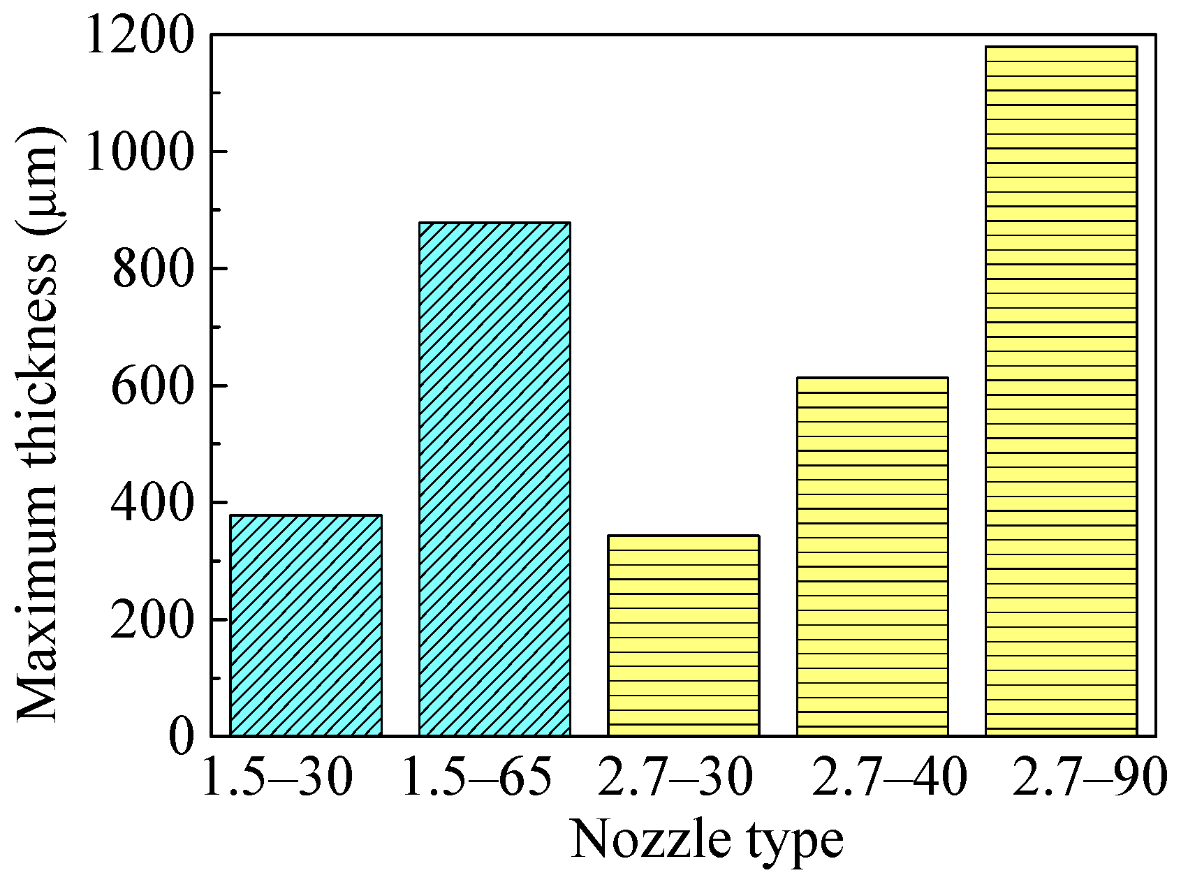
  • With a longer convergent section of the nozzle, the edges of the single-pass deposits change from rough to smooth, and deposit width increases. In addition, the deposit microstructure changes from porous to dense, and the particles in the 2.7–90 deposit are tightly bonded. The increase in the maximum thickness and microhardness of the deposit indicate the improved deposition efficiency and mechanical properties.

Author Contributions

C.C.: conceptualization, investigation, methodology, numerical calculation, data curation, writing, and editing; W.L.: conceptualization, investigation, methodology, resources, writing—review & editing, funding acquisition; Z.Z.: conceptualization, software, numerical calculation, visualization; X.Y.: methodology, writing—review & editing; Y.X.: investigation, visualization. All authors have read and agreed to the published version of the manuscript.

Funding

This research was funded by the National Natural Science Foundation of China, Grant Number 51875471 and the State Key Laboratory of Solidification Processing of China, Grant Number 2019-QZ-01.

Institutional Review Board Statement

Not applicable.

Informed Consent Statement

Not applicable.

Data Availability Statement

Data sharing not applicable.

Acknowledgments

The authors would like to express their gratitude for financial support from the National Natural Science Foundation of China (51875471) and the State Key Laboratory of Solidification Processing (NPU, China) (2019-QZ-01).

Conflicts of Interest

The authors declare that there is no conflict of interest regarding the publication of this paper.

References

  1. Raoelison, R.N.; Verdy, C.; Liao, H. Cold gas dynamic spray additive manufacturing today: Deposit possibilities, technological solutions and viable applications. Mater. Des. 2017, 133, 266–287. [Google Scholar] [CrossRef]
  2. Yin, S.; Cavaliere, P.; Aldwell, B.; Jenkins, R.; Liao, H.; Li, W.Y.; Lupoi, R. Cold spray additive manufacturing and repair: Fundamentals and applications. Addit. Manuf. 2018, 21, 628–650. [Google Scholar] [CrossRef]
  3. Yin, S.; Cizek, J.; Cupera, J.; Hassani, M.; Luo, X.T.; Jenkins, R.; Xie, Y.C.; Li, W.Y.; Lupoi, R. Formation conditions of vortex-like intermixing interfaces in cold spray. Mater. Des. 2021, 200, 109444. [Google Scholar] [CrossRef]
  4. Xie, X.; Ma, Y.; Chen, C.; Ji, G.; Verdy, C.; Wu, H.; Chen, Z.; Yuan, S.; Normand, B.; Yin, S.; et al. Cold spray additive manufacturing of metal matrix composites (MMCs) using a novel nano-TiB2-reinforced 7075Al powder. J. Alloys Compd. 2020, 819, 152962. [Google Scholar] [CrossRef]
  5. Li, W.Y.; Assadi, H.; Gaertner, F.; Yin, S. A Review of advanced composite and nanostructured coatings by solid-state cold spraying process. Crit. Rev. Solid State Mater. Sci. 2018, 44, 109–156. [Google Scholar] [CrossRef] [Green Version]
  6. Li, W.Y.; Cao, C.C.; Yin, S. Solid-state cold spraying of Ti and its alloys: A literature review. Prog. Mater. Sci. 2019, 110, 100633. [Google Scholar] [CrossRef]
  7. Bagherifard, S.; Monti, S.; Zuccoli, M.V.; Riccio, M.; Kondás, J.; Guagliano, M. Cold spray deposition for additive manufacturing of freeform structural components compared to selective laser melting. Mater. Sci. Eng. A. 2018, 721, 339–350. [Google Scholar] [CrossRef]
  8. Feng, Y.; Li, W.Y.; Guo, C.; Gong, M.; Yang, K. Mechanical property improvement induced by nanoscaled deformation twins in cold-sprayed Cu coatings. Mater. Sci. Eng. A. 2018, 727, 119–122. [Google Scholar] [CrossRef]
  9. Li, W.Y.; Wu, D.; Hu, K.W.; Xu, Y.X.; Yang, X.W.; Zhang, Y. A comparative study on the employment of heat treatment, electric pulse processing and friction stir processing to enhance mechanical properties of cold-spray-additive-manufactured copper. Surf. Coat. Technol. 2021, 409, 126887. [Google Scholar] [CrossRef]
  10. Huang, C.; Li, W.Y.; Feng, Y.; Xie, Y.; Planche, M.-P.; Liao, H.; Montavon, G. Microstructural evolution and mechanical properties enhancement of a cold-sprayed Cu Zn alloy coating with friction stir processing. Mater. Charact. 2017, 125, 76–82. [Google Scholar] [CrossRef]
  11. Liu, T.; Leazer, J.D.; Menon, S.K.; Brewer, L.N. Microstructural analysis of gas atomized Al-Cu alloy feedstock powders for cold spray deposition. Surf. Coat. Technol. 2018, 350, 621–632. [Google Scholar] [CrossRef]
  12. Zhao, H.; Tan, C.; Yu, X.; Ning, X.; Nie, Z.; Cai, H.; Wang, F.; Cui, Y. Enhan-ced reactivity of Ni-Al reactive material formed by cold spraying combined with cold-pack rolling. J. Alloys Compd. 2018, 741, 883–894. [Google Scholar] [CrossRef]
  13. Liu, T.; Leazer, J.D.; Brewer, L.N. Particle deformation and microstructure evolution during cold spray of individual Al-Cu alloy powder particles. Acta Mater. 2019, 168, 13–23. [Google Scholar] [CrossRef]
  14. Zeng, G.; Zahiri, S.H.; Gulizia, S.; Chen, Y.; Xu, C.; Chen, X.-B.; Cole, I. A comparative study of cell growth on a cold sprayed Ti-Ta composite. J. Alloys Compd. 2020, 826, 154014. [Google Scholar] [CrossRef]
  15. Li, W.Y.; Guo, X.P.; Verdy, C.; Dembinski, L.; Liao, H.L.; Coddet, C. Improvement of microstructure and property of cold-sprayed Cu-4 at.%Cr-2 at.%Nb alloy by heat treatment. Scripta Mater. 2006, 55, 327–330. [Google Scholar] [CrossRef]
  16. Wu, H.; Zhang, L.; Liu, C.; Mai, Y.; Zhang, Y.; Jie, X. Deposition of Zn-G/Al composite coating with excellent cathodic protection on low-carbon steel by l-ow-pressure cold spraying. J. Alloys Compd. 2020, 821, 153483. [Google Scholar] [CrossRef]
  17. Yang, K.; Li, W.Y.; Niu, P.; Yang, X.; Xu, Y. Cold sprayed AA2024/Al2O3 metal matrix composites improved by friction stir processing: Microstructure characterization, mechanical performance and strengthening mechanisms. J. Alloys Compd. 2018, 736, 115–123. [Google Scholar] [CrossRef]
  18. Huang, C.J.; Li, W.Y.; Zhang, Z.; Fu, M.; Planche, M.-P.; Liao, H.; Montavon, G. Modification of a cold sprayed SiCp/Al5056 composite coating by friction stir processing. Surf. Coat. Technol. 2016, 296, 69–75. [Google Scholar] [CrossRef]
  19. Wang, X.; Zhang, L.; Zhou, X.; Wu, W.; Jie, X. Corrosion behavior of Al2O3-reinforced graphene encapsulated Al composite coating fabricated by low pressure cold spraying. Surf. Coat. Technol. 2020, 386, 125486. [Google Scholar] [CrossRef]
  20. Yang, K.; Li, W.Y.; Xu, Y.X.; Yang, X.W. Using friction stir processing to augment corrosion resistance of cold sprayed AA2024/Al2O3 composite coatings. J. Alloys Compd. 2019, 774, 1223–1232. [Google Scholar] [CrossRef]
  21. Ma, W.; Xie, Y.; Chen, C.; Fukanuma, H.; Wang, J.; Ren, Z.; Huang, R. Microstructural and mechanical properties of high-performance Inconel 718 alloy by cold spraying. J. Alloys Compd. 2019, 792, 456–467. [Google Scholar] [CrossRef]
  22. Luo, X.T.; Yao, M.L.; Ma, N.; Takahashi, M.; Li, C.J. Deposition behavior, microstructure and mechanical properties of an in-situ micro-forging assisted cold spray enabled additively manufactured Inconel 718 alloy. Mater. Design. 2018, 155, 384–395. [Google Scholar] [CrossRef]
  23. Sun, W.; Bhowmik, A.; Tan, A.W.Y.; Li, R.; Xue, F.; Marinescu, I.; Liu, E. Improving microstructural and mechanical characteristics of cold-sprayed Inconel 718 deposits via local induction heat treatment. J. Alloys Compd. 2019, 797, 1268–1279. [Google Scholar] [CrossRef]
  24. Aydin, H.; Alomair, M.; Wong, W.; Vo, P.; Yue, S. Cold spray ability of mixed commercial purity Ti plus Ti6Al4V metal powders. J. Therm. Spray Technol. 2017, 26, 360–370. [Google Scholar] [CrossRef] [Green Version]
  25. Tan, A.W.Y.; Sun, W.; Phang, Y.P.; Dai, M.; Marinescu, I.; Dong, Z.; Liu, E. Effects of traverse scanning speed of spray nozzle on the microstructure and mechanical properties of cold-sprayed Ti6Al4V coatings. J. Therm. Spray Technol. 2017, 26, 1484–1497. [Google Scholar] [CrossRef]
  26. Sun, W.; Tan, A.W.Y.; Marinescu, I.; Toh, W.Q.; Liu, E. Adhesion, tribological and corrosion properties of cold-sprayed CoCrMo and Ti6Al4V coatings on 6061-T651 Al alloy. Surf. Coat. Technol. 2017, 326, 291–298. [Google Scholar] [CrossRef]
  27. Munagala, V.N.V.; Imbriglio, S.I.; Chromik, R.R. The influence of powder properties on the adhesion strength and microstructural evolution of cold sprayed Ti6Al4V single splats. Mater. Lett. 2019, 244, 58–61. [Google Scholar] [CrossRef]
  28. Li, W.Y.; Yang, K.; Yin, S.; Yang, X.W.; Xu, Y.X.; Lupoi, R. Solid-state additive manufacturing and repairing by cold spraying: A review. J. Mater. Sci. Technol. 2018, 34, 440–457. [Google Scholar] [CrossRef]
  29. Li, W.Y.; Cao, C.C.; Wang, G.Q.; Wang, F.F.; Xu, Y.X.; Yang, X.W. ‘Cold spray +’ as a new hybrid additive manufacturing technology: A literature review. Sci. Technol. Weld. Join. 2019, 24, 420–445. [Google Scholar] [CrossRef]
  30. Luo, X.T.; Wei, Y.K.; Wang, Y.; Li, C.J. Microstructure and mechanical property of Ti and Ti6Al4V prepared by an in-situ shot peening assisted cold spraying. Mater. Des. 2015, 85, 527–533. [Google Scholar] [CrossRef]
  31. Zhou, H.X.; Li, C.J.; Yang, H.; Luo, X.T.; Yang, G.; Li, W.Y.; Hussain, T.; Li, C.J. Pores structure change induced by heat treatment in cold-sprayed Ti6Al4V coating. J. Therm. Spray Technol. 2019, 28, 1199–1211. [Google Scholar] [CrossRef]
  32. Chen, C.; Xie, Y.; Yan, X.; Yin, S.; Fukanuma, H.; Huang, R.; Zhao, R.; Wang, J.; Ren, Z.; Liu, M.; et al. Effect of hot isostatic pressing (HIP) on microstructure and mechanical properties of Ti6Al4V alloy fabricated by cold spray additive manufacturing. Addit. Manuf. 2019, 27, 595–605. [Google Scholar] [CrossRef]
  33. Yin, S.; Meyer, M.; Li, W.Y.; Liao, H.; Lupoi, R. Gas flow, particle acceleration, and heat transfer in cold spray: A review. J. Therm. Spray Technol. 2016, 25, 874–896. [Google Scholar] [CrossRef]
  34. Yin, S.; Zhang, M.; Guo, Z.; Liao, H.; Wang, X. Numerical investigations on the effect of total pressure and nozzle divergent length on the flow character and particle impact velocity in cold spraying. Surf. Coat. Technol. 2013, 232, 290–297. [Google Scholar] [CrossRef]
  35. Li, W.Y.; Li, C.J. Optimal design of a novel cold spray gun nozzle at a limited space. J. Therm. Spray Technol. 2005, 14, 391–396. [Google Scholar] [CrossRef]
  36. Li, W.Y.; Liao, H.; Douchy, G.; Coddet, C. Optimal design of a cold spray nozzle by numerical analysis of particle velocity and experimental validation with 316L stainless steel powder. Mater. Des. 2007, 28, 2129–2137. [Google Scholar] [CrossRef]
  37. Alhulaifi, A.S.; Buck, G.A.; Arbegast, W.J. Numerical and experimental investigation of cold spray gas dynamic effects for polymer coating. J. Therm. Spray Technol. 2012, 21, 852–862. [Google Scholar] [CrossRef]
  38. Belbaki, A.; Mebdoua-Lahmar, Y. Influence of diverging section length on the supersonic jet delivered from micro-nozzle: Application to cold spray coating process. In Applied Mechanics, Behavior of Materials, and Engineering Systems; Boukharouba, T., Pluvinage, G., Azouaoui, K., Eds.; Springer: New York, NY, USA, 2017; pp. 465–473. [Google Scholar]
  39. Jung, H.B.; Park, J.I.; Park, S.H.; Kim, H.J.; Lee, C.H.; Han, J.W. Effect of the expansion ratio and length ratio on a gas-particle flow in a converging-dive-rging cold spray nozzle. Met. Mater. Int. 2009, 15, 967–970. [Google Scholar] [CrossRef]
  40. Sova, A.; Okunkova, A.; Grigoriev, S.; Smurov, I. Velocity of the particles accelerated by a cold spray micronozzle: Experimental measurements and numerical simulation. J. Therm. Spray Technol. 2012, 22, 75–80. [Google Scholar] [CrossRef]
  41. Sova, A.; Smurov, I.; Doubenskaia, M.; Petrovskiy, P. Deposition of aluminum powder by cold spray micronozzle. Int. J. Adv. Manuf. Technol. 2017, 95, 3745–3752. [Google Scholar] [CrossRef]
  42. Buhl, S.; Breuninger, P.; Antonyuk, S. Optimization of a Laval nozzle for energy-efficient cold spraying of microparticles. Mater. Manuf. Processes. 2017, 33, 115–122. [Google Scholar] [CrossRef]
  43. Faizan-Ur-Rab, M.; Zahiri, S.H.; King, P.C.; Busch, C.; Masood, S.H.; Jahedi, M.; Nagarajah, R.; Gulizia, S. Utilization of titanium particle impact location to validate a 3D multicomponent model for cold spray additive manufacturing. J. Therm. Spray Technol. 2017, 26, 1874–1887. [Google Scholar] [CrossRef]
  44. Lupoi, R. Current design and performance of cold spray nozzles: Experimental and numerical observations on deposition efficiency and particle velocity. Surf. Eng. 2013, 30, 316–322. [Google Scholar] [CrossRef] [Green Version]
  45. Daroonparvar, M.; Kasar, A.-K.; Khan, M.-U.-F.; Menezes, P.-L.; Kay, C.-M.; Misra, M.; Gupta, R.-K. Improvement of wear, pitting corrosion resistance and repassivation ability of mg-based alloys using high pressure cold sprayed (HPCS) commercially pure-titanium coatings. Coatings 2021, 11, 57. [Google Scholar] [CrossRef]
  46. Zórawski, W.; Molak, R.; Madry, J.; Sienicki, J.; Góral, A.; Makrenek, M.; Scendo, M.; Dobosz, R. Experimental and numerical investigations of titanium deposition for cold spray additive manufacturing as a function of standoff distance. Materials 2021, 14, 5492. [Google Scholar] [CrossRef]
  47. Schmidt, T.; Gärtner, F.; Assadi, H.; Kreye, H. Development of a generalized parameter window for cold spray deposition. Acta Mater. 2006, 54, 729–742. [Google Scholar] [CrossRef]
  48. Li, W.Y.; Zhang, C.; Guo, X.; Li, C.J.; Liao, H.; Coddet, C. Study on impact fusion at particle interfaces and its effect on coating microstructure in cold spraying. Appl. Surf. Sci. 2007, 254, 517–526. [Google Scholar] [CrossRef]
  49. Assadi, H.; Kreye, H.; Gartner, F.; Klassen, T. Cold spraying-A materials perspective. Acta Mater. 2016, 116, 382–407. [Google Scholar] [CrossRef] [Green Version]
  50. Cao, C.C.; Han, T.P.; Xu, Y.X.; Li, W.Y.; Yang, X.W.; Hu, K.W. The associated effect of powder carrier gas and powder characteristics on the optimal design of the cold spray nozzle. Surf. Eng. 2020, 36, 1081–1089. [Google Scholar] [CrossRef]
  51. Li, C.J.; Li, W.Y. Deposition characteristics of titanium coating in cold spraying. Surf. Coat. Technol. 2003, 167, 278–283. [Google Scholar] [CrossRef]
Figure 1. Nozzle internal dimensions used in the numerical model.
Coatings 12 00210 g001
Figure 2. Ti6Al4V particle microtopography (a) and size distribution (b).
Coatings 12 00210 g002
Figure 3. Five different nozzles (a), 2.7–90 nozzle and substrate (b), and single-pass deposits made using the 2.7–90 nozzle (c).
Coatings 12 00210 g003
Figure 4. Gas temperature distribution in the nozzle for various convergent section lengths.
Coatings 12 00210 g004
Figure 5. Gas temperature profile along the nozzle axis.
Coatings 12 00210 g005
Figure 6. Particle temperature along with the nozzle axis (a), and the particle temperatures at the nozzle throat and upon impact on the substrate (b). Note: particle diameter is 25 μm.
Coatings 12 00210 g006
Figure 7. Particle temperatures upon impact on the substrate.
Coatings 12 00210 g007
Figure 8. Particle temperature profiles along the nozzle axis (a) and with flying time (b), and the changes in particle total flying time and temperature with particle diameter (c) in the case of nozzle 2.7–90.
Coatings 12 00210 g008
Figure 9. Gas velocity along the nozzle axis.
Coatings 12 00210 g009
Figure 10. Particle kinetic energy along with the nozzle axis. Please note that the particle diameter is 25 μm.
Coatings 12 00210 g010
Figure 11. The kinetic energy of different-sized particles upon impact on the substrate. Please note that the kinetic energy value of the 5 μm particles is between 1.02 × 10⁻⁷ J and 1.22 × 10⁻⁷ J.
Coatings 12 00210 g011
Figure 12. The surface morphology and maximum width of five different single-pass deposits: (a) 1.5–30; (b) 1.5–65; (c) 2.7–30; (d) 2.7–40; (e) 2.7–90; and (f) maximum width.
Coatings 12 00210 g012
Figure 13. Cross-sectional microstructure of single-pass deposits.
Coatings 12 00210 g013
Figure 14. Cross-sectional microstructure of single-pass deposit in 2.7–90 case: (a) low-magnification scanning electron microscopy; (b) high-magnification scanning electron microscopy in the purple solid frame of (a). Note: the blue dashed line indicates the bonding interface between particles.
Coatings 12 00210 g014
Figure 15. The high magnification microstructure of the deposit in the 2.7–90 case: (a) high-magnification scanning electron microscopy and tiny selection area A; (b) high-magnification scanning electron microscopy and tiny selection area B; (c) area scan results of tiny selected area A; (d) area scan results of tiny selected area B. Note: the blue dashed line indicates the bonding interface between particles.
Coatings 12 00210 g015
Figure 16. The maximum thickness achieved with single-pass deposits.
Coatings 12 00210 g016
Figure 17. The microhardness of single-pass deposits.
Coatings 12 00210 g017
Table 1. Different studies on the internal dimensions of the Laval nozzle [34,35,36,37,38,39,40,41,42,43,44].
MaterialInlet Diameter
(mm)
Convergent Length
(mm)
Throat Diameter
(mm)
Divergent Length
(mm)
Exit Diameter
(mm)
Experimental ValidationReferences
Cu17302.280–4404.4, 6.22, 7.62N[34]
Cu8102402, 3, 4, 5, 6, 7, 8Y[35]
316L stainless18.2542.7, 5.467.6, 120, 27010.4-12.4Y[36]
Polymer9.84.442.66133.686.3Y[37]
N/A14202.759.9, 69.9, 79.9, 89.98.36N[38]
AlN/A17, 22, 27, 32, 42, 572.742, 57, 67, 72, 77, 824.32, 5.58, 6.84, 8.5N[39]
AlN/AN/A0.5201N[40]
AlN/AN/A0.5201Y[41]
Ti1050.8251.5Y[42]
TiN/A43.62.71296.6Y[43]
Ti1015.5, 20, 301, 1.34180, 1903, 4Y[44]
Note: Y: yes, N: no, and N/A: not available.
Table 2. Material properties [47,48,49].
MaterialDensity (kg/m3)Thermal Conductivity (W/m/K)Heat Capacity (J/kg/K)Melting Point (°C)Yield Strength (MPa)Ultimate Strength (MPa)Critical Velocity for CSAM (m/s)
Cu888039838666090210451
Al26882379059334480482
Ti450621.95221680140220712
Ti6Al4V44207.653716608809501013
Table 3. The sizes of the different nozzles.
TypeDi (mm)Lc (mm)Dt (mm)Ld (mm)De (mm)Total Length
(mm)
1.5–3020301.51703.6200
1.5–6565235
2.7–30302.72106240
2.7–4040250
2.7–9090300
Publisher’s Note: MDPI stays neutral with regard to jurisdictional claims in published maps and institutional affiliations.

