Article

Investigation of Microstructure, Residual Stress, and Hardness of Ti-6Al-4V after Plasma Nitriding Process with Different Times and Temperatures

by
Goratouch Ongtrakulkij
1,
Julathep Kajornchaiyakul
2,
Katsuyoshi Kondoh
3 and
Anak Khantachawana
1,4,*
1
Department of Mechanical Engineering, Faculty of Engineering, King Mongkut’s University of Technology Thonburi (KMUTT), Bangkok 10140, Thailand
2
National Metal and Materials Technology Center (MTEC), National Science and Technology Development Agency (NSTDA), Pathumthani 12120, Thailand
3
Department of Composite Materials Processing, Joining and Welding Research Institute, Osaka University, 11-1 Mihogaoka, Ibaraki, Osaka 567-0047, Japan
4
Biological Engineering Program, Faculty of Engineering, King Mongkut’s University of Technology Thonburi (KMUTT), Bangkok 10140, Thailand
*
Author to whom correspondence should be addressed.
Coatings 2022, 12(12), 1932; https://doi.org/10.3390/coatings12121932
Submission received: 11 November 2022 / Revised: 30 November 2022 / Accepted: 3 December 2022 / Published: 8 December 2022

Abstract

:
The residual stress and hardness generated by the nitriding process are important parameters for increasing the bending fatigue strength to Ti-6Al-4V. Therefore, this research is focused on the analysis of residual stress and hardness, including surface morphology and microstructure generated by the nitriding process at different times and temperatures. The plasma nitriding at temperatures of 750 °C and 800 °C with times of 5 h and 10 h were selected in this research. After plasma nitriding, the material would have residual compressive stress and higher hardness, including changes in the surface morphology and microstructure. The results also indicated that higher temperature and processing times generated more surface roughness and thickness in the compound layer, resulting in higher surface hardness. Moreover, higher time and temperature could generate deeper residual compressive stress and case depth hardness. This research revealed maximum hardness in the cross-sectional analysis of 643 HV and residual compressive stress of −65.3 MPa. In conclusion, the depth of the residual stress and case depth hardness were well compatible with the depth of the diffusion layer of plasma-nitrided Ti-6Al-4V, which confirmed the effect of plasma nitriding.

1. Introduction

Titanium alloy, Ti-6Al-4V, is one of the key materials in many industries, such as aerospace and automotive, including biomedical applications. The reasons that Ti-6Al-4V is typically selected to be used in many medical devices are caused by high strength, high corrosion resistance, effective biocompatibility, lightweight, and low Young’s modulus [1,2,3,4,5]. Most of the Ti-6Al-4V in medical devices are designed to be capable of handling bending forces such as bone plate and spinal fixation [6,7,8]. However, some journal papers reported that medical devices made of Ti-6Al-4V were able to be distorted or failed from high bending force and bending fatigue [9,10,11,12], although Ti-6Al-4V is found to have almost the highest strength and is considerably higher than those of other medical metals. The device failure consequently leads to re-surgery, which may increase costs and the risks of disability to the patients. Nowadays, improving the strength of Ti-6Al-4V is considered a critical issue in engineering fields. However, the methods of improving strength must be performed under the control of biocompatibility and Young’s modulus due to the stress shielding effect [13,14,15].
Many surface treatments are offered to improve the bending fatigue strength of Ti-6Al-4V by increasing hardness and residual compressive stress. Nitriding is one of the surface treatments using heat treatment to turn nitrogen into metal, resulting in an increase in the residual compressive stress and hardness in depth or case depth hardness [16,17]. Both increasing values help to increase the bending fatigue strength [16,18], while biocompatibility still remains [19,20]. Nitriding has been classified into three types which are gas nitriding, liquid nitriding, and plasma nitriding. After the process, there are three main layers found on the surface, which are the compound layer, diffusion layer, and base metal layer [21,22]. As above mentioned, nitriding seems to be one of the most effective ways to improve the fatigue strength of medical devices. However, there is a problem found when applying the nitriding process to Ti-6Al-4V. The compound layers of nitrided Ti-6Al-4V, which are δ-TiN, Ti2N, and α-case, are found with high hardness after higher temperatures, resulting in lower toughness which leads to a decrease in bending fatigue strength [22,23,24,25]. In addition, it is found that the temperature required for the nitriding of Ti-6Al4V is higher than those of steel alloys which is not over 550 °C due to the higher hardness of diffusion [22], which would increase the thickness of the compound layer [24,25,26]. However, some of the studies reported that compound layer thickness could be decreased by nitriding at temperatures lower than 800 °C in a short time; this was able to improve the bending fatigue strength of Ti-6Al-4V [25,26], including the removal of the compound layer by polishing or sandblast [25,27,28,29]. The removal of the compound layer would not lead to the crack propagation being extended from the surface to surface due to the low toughness removed from the compound layer. The crack propagation starts from the surface to the inside of the material, similar to the normal crack propagation of the material from bending stress [28,29]. The main layer supported by an increasing bending strength is the diffusion layer or Ti(N). In this layer, nitrogen is diffused into the titanium structure, which subsequently introduces residual compressive stress and high hardness [27,28,29]. Thus, less compound layer thickness with the height and depth of residual compressive stress or high diffusion layer is considered as the key target upon the application of this process towards improving the bending fatigue strength. However, there are only a few journal papers that mention residual compressive stress from the nitriding process, especially in Ti-6Al-4V, and the relationships between residual stress, hardness, and microstructure. In addition, the effect of the main parameters of nitriding, such as time and temperature, on the increasing residual compressive stress, hardness, and compound layer thickness of Ti-6Al-4V is also indicated in a few examples of the literature.
According to various journal papers which regard an increase in the bending fatigue strength through the nitriding process, based on increasing residual compressive stress and hardness, while having less compound layer thickness generated, few results of the property analysis in Ti-6Al-4V were shown. Thus, a study on residual stress, the increase in hardness, microstructure analysis on the compound layer, as well as the depth of the diffusion layer of nitrided Ti-6Al-4V is considered significant to be confirmed upon mentioned parameters of increasing bending fatigue strength. Therefore, the aim of this research is to investigate the surface morphology, the microstructure for analysis of the compound layer and depth of diffusion layer, residual compressive stress, and the hardness changed from the nitriding process, including the relationships among these factors. Furthermore, due to the main parameters of the nitriding process causing a huge effect on these properties, this research also aims to study the effects of time and temperature of nitriding to obtain results of the parameters on the performances of Ti-6Al-4V. The experiments on surface observation and roughness are to be applied as an experiment of surface morphology analysis, while the microstructure is to be observed in cross-sectional microstructure analysis through a scanning electron microscope (SEM) and identified through the phase of materials by X-ray diffraction (XRD) on the surface. The changes in the hardness and residual stress are to be supported by Vickers hardness and XRD on further analysis through the residual stress method.

2. Materials and Methods

2.1. Materials and Preparation

Titanium alloy, Ti-6Al-4V medical grade, was purchased from Baoji Energy Titanium Co., Ltd., Baoji, China. The Ti-6Al-4V was applied in the form of a sheet with a thickness of 3.5 mm following ASTM F136 [30]. The chemical compositions of the material are shown in Table 1. The physical properties obtained from the mill test certificate were 964 MPa of tensile strength and 889 MPa of yield strength with 17% elongation. The samples were cut into the size of 45 mm × 35 mm, pierced with a 3 mm diameter hole on top for hanging in the nitriding chamber, and polished up to 1500 grit with abrasive paper. After polishing, the material was cleaned with ethanol to prevent contamination.

2.2. Plasma Nitriding

Plasma nitriding was selected for this study as its diffusion is more stable, and the compound layer is less than another nitriding process [31,32]. The process was implemented by hanging specimens with the hanger through the hole of the specimens for performing the plasma nitriding effect on both sides of the specimens, and this was applied with a vacuum pressure of 400 Pa, a voltage of 380 V, and an electric current of 7–10 A. Each nitriding condition was conducted in a pure N2 atmosphere. The temperature varied between 750 °C and 800 °C with varied processing times between 5 and 10 h. The process aimed to obtain the effects of time and temperature on residual compressive stress, hardness, and microstructure. The samples after the plasma nitriding process were selected only from the center of the specimen to prevent the effects of cutting and hole drilling. The conditions of plasma nitriding found in this research are described in Table 2.

2.3. Surface Observation and Roughness

The camera photo was used to compare the surface changes in terms of color change after the nitriding process was applied. Then, the optical microscope from Olympus (DP21, Olympus Corporation, Tokyo, Japan) with a magnification of 50 times was utilized to compare the difference in the surface morphology. Moreover, the scanning electron microscope (SEM) from Joel, model JCM-7000 (Jeol Ltd., Tokyo, Japan), with a magnification of 3000 times, was used to observe the microstructure in high resolution. The surface roughness was measured by the MarSurf M 300 surface roughness tester (Mahr GmbH, Göttingen, Germany) following the JIS B0601 (2001) standard to control the measurement and calculation [33]. The cut-off value in the measurement was 0.8 mm, while the total length was 5.2 mm. The vertical and horizontal line of three samples were used to measure roughness. The arithmetical mean roughness (Ra) and ten-point mean roughness (Rz) was used to analyze the difference between each condition of the surface treatment.

2.4. Phase Identification

The X-ray diffraction (XRD, D8 Advance Eco, Bruker AXS GmbH, Karlsuhe, Germany) was used to analyze the crystalline phase of different nitriding conditions. The 40 Kv and 25 mA with Cu-Kα radiation were selected as the power of the X-ray source. The scanning angle range (2θ) started from 30° to 80° with 0.3 s in time/step and 0.0202° in the increment angle.

2.5. Microstructure Analysis

The microstructure of Ti-6Al-4V in different conditions through the nitriding process was analyzed following cross-section analysis in the roller direction side, prepared by cutting and polishing up to 2000 grit, with 0.3 μm and 0.1 μm of alumina, which was then polished with OP-S in the final process. The scanning electron microscope (SEM, JCM-7000, Jeol Ltd., Tokyo, Japan) was supplemented in this analysis. Magnifications of 500 times and 1700 times were selected to examine the depth of the diffusion layer and compound layer.

2.6. Residual Stress Analysis

The residual stress was analyzed by X-ray diffraction (XRD, D8 Advance Eco, Bruker AXS GmbH, Karlsuhe, Germany) with 40 Kv and 25 mA and radiation at Cu-Kα. The scanning angle range (2θ) between 135° and 145° with 0.6 s in time/step and 0.0202° in increment angle was used to identify the peak of (3 1 1) α-Ti. The fixed incidence angle method by varying the psi angle (ψ) between 0° and 45° and the “sin2 ψ” calculation method by using a slope of sin2 ψ vs. θ graph was selected as a method for calculating the residual stress [34,35]. The data started at 10 μm to prevent disturbance on the compound layer at the surface. The final data collected were 120 μm depth from the surface, given no residual stress in all the conditions. Electropolishing was used as a drilling method with 10% of Perchloric acid and 90% of Methanol as an electrolyte.

2.7. Hardness Analysis

The hardness analysis was divided into 2 parts, top surface hardness, and cross-section hardness, for analyzing the hardness in depth. Both parts were analyzed by HMV g Micro Vickers hardness from Shimadzu (Kyoto, Japan) and were controlled with ASTM E92 [36]. The testing temperature was controlled at 25 °C. The 3 samples for each test were prepared to measure hardness on the surface and cross-section. The force of surface hardness was 1.961 N (HV0.2) with 10 s of holding time with a random indentation on the surface. The cross-sectional hardness was prepared by having samples cut and polished with sandpaper up to 1500 grit, then using hot mounting to maintain a position and applying a force of 245.2 mN (HV0.025) with 10 s of holding time upon the condition of measurement. The measurement of the cross-sectional hardness started from 10 μm to 120 μm depth from the surface by increasing the depth from each point to 10 μm. The distance between each indentation was controlled by ASTM E92.

3. Results and Discussion

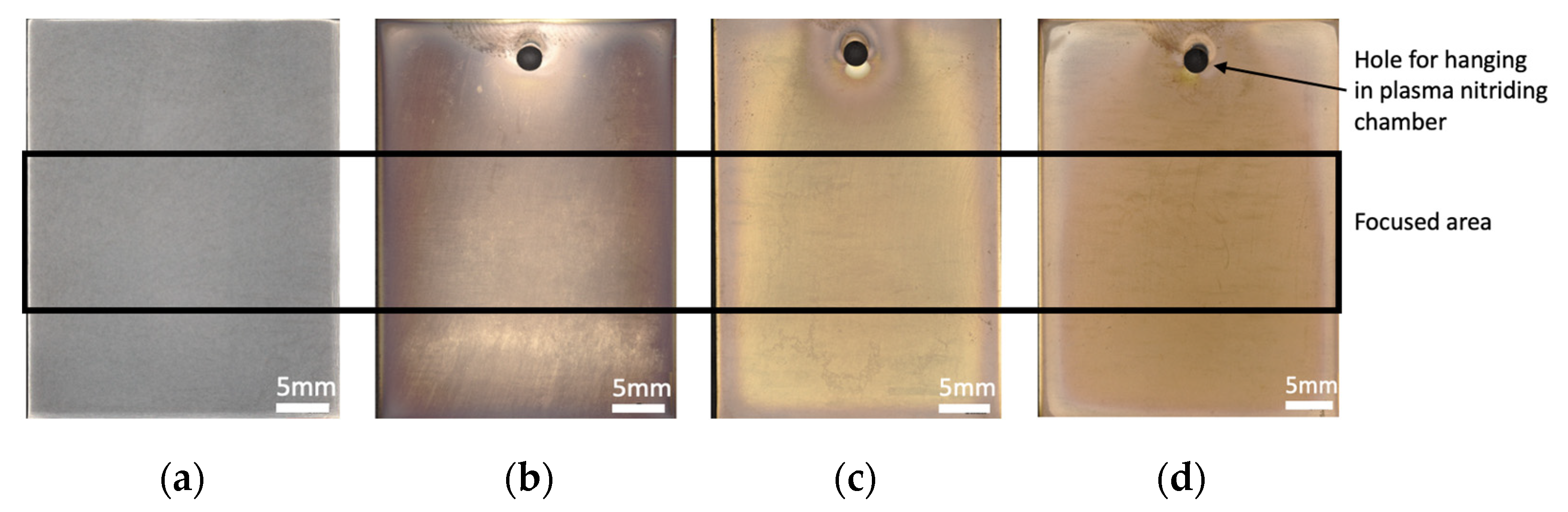
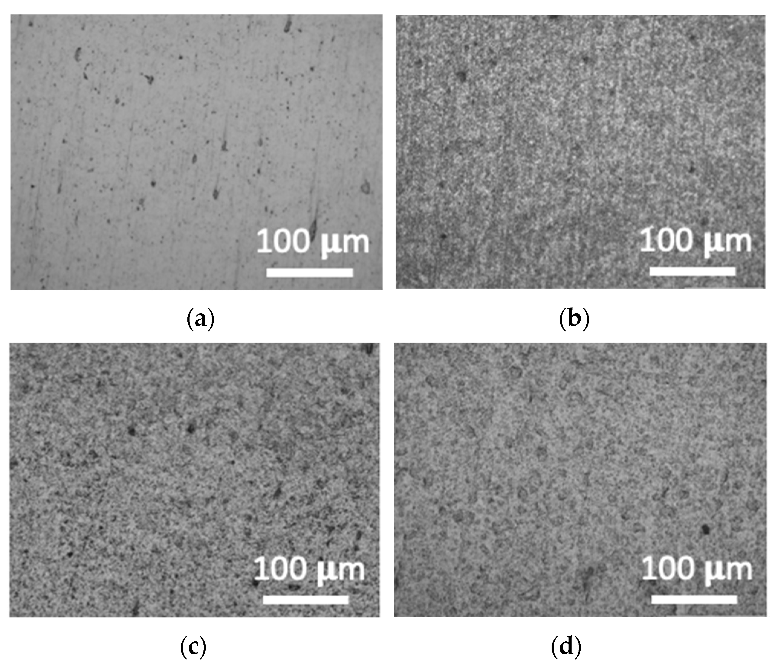
3.1. Surface Observation and Roughness

Figure 1 shows the overall observation of the surface revealed and focus areas of all experiments used in this research. The results showed that the plasma nitriding process was able to change the color of the Ti-6Al-4V surface to yellow, as shown in Figure 1. Changes to the surface color after applying plasma nitriding significantly indicated that the compound had been generated on the surface and, thus, the properties of the surface were accordingly changed [25,37]. The different conditions of plasma nitriding showed different colors on the surface, leading to differences in the compound layer composition, which is further described in the next section.
Following the application of the optical microscope to observe further differences, the images of the surface from different nitriding conditions are shown in Figure 2. After the plasma nitriding process, the surface of Ti-6Al-4V was found with small dimples which were rougher than those of the untreated surface. The reason for the high roughness on the surface after the plasma nitriding process could be explained by the formation of δ-TiN and Ti2N in the compound layer, which was similarly formed into small particles and joined in the form of hillocks as shown in the scanning electron microscope (SEM) images in Figure 3 [37,38,39]. The surface after plasma nitriding with 750 °C for 5 h identified the lowest surface roughness compared to the specimen with a longer time and higher temperature of surface treatment. It was found that the biggest dimple size was obtained from the plasma nitriding process at 800 °C for 5 h. With the increasing time and temperature of plasma nitriding, particle sizes of δ-TiN and Ti2N also increased, leading to huge hillocks, which caused large dimples on the surface under the condition of 800 °C for 5 h.
The results of the surface roughness, including the arithmetical mean roughness (Ra) and ten-point mean roughness (Rz) after different plasma nitriding conditions, are shown in Figure 4. The results show that Ra and Rz were increased after applying the plasma nitriding process. However, it is noted that the surface roughness is related to the stress concentration, which is also able to decrease fatigue strength. The Ra and Rz of the untreated Ti-6Al-4V are 0.082 μm and 0.855 μm, respectively, while, after the plasma nitriding process at 750 °C for 5 h, Ra and Rz increased to 0.158 μm and 1.311 μm, respectively. Moreover, with an increase in the plasma nitriding time up to 10 h with the temperature remaining at 750 °C, Ra and Rz were increased to 0.205 μm and 1.635 μm. By increasing the temperature of the plasma nitriding process to 800 °C for 5 h, the results show that the highest Ra and Rz were 0.271 μm and 2.044 μm, respectively. The results of the roughness identically support the hillocks, as shown in Figure 2, and the differences in each condition. The study indicates that higher temperature and treatment time significantly affects the surface roughness, which must be taken into consideration when applied towards increasing fatigue strength.

3.2. Phase Identification

The phases of Ti6-Al-4V on the surface after different plasma nitriding conditions detected by the X-ray diffraction (XRD) are shown in Figure 5. The untreated Ti-6Al-4V revealed only the α-Ti phase, while the Ti2N and δ-TiN phases were found in plasma nitrided with Ti-6Al-4V. The result confirmed that the compound layer of plasma-nitrided Ti-6Al-4V contained Ti2N and δ-TiN. The lowest time and temperature condition of plasma nitriding at 750 °C for 5 h showed the lowest intensity of the Ti2N and δ-TiN phases. While increasing the treatment time to 10 h at 750 °C, the intensity of the Ti2N and δ-TiN phases was higher. The highest intensity of the Ti2N and δ-TiN phases was found under the condition of 800 °C for 5 h. However, after the plasma nitriding process, the intensity of the α-Ti phase strongly decreased correspondingly to the increasing time and temperature. The result of the increasing intensity of Ti2N and δ-TiN while α-Ti was reduced could be explained as a reaction of the changing α-Ti to Ti2N followed by δ-TiN when nitrogen was diffused into the structure. Thus, the increasing temperature would increase the rate of changing α-Ti to Ti2N and δ-TiN while increasing the time affected by the increase in the number of changes [25,40]. The higher intensity of the Ti2N and δ-TiN phases possibly led to a higher compound layer thickness. Accordingly, further analysis was conducted and is shown in the microstructure analysis section.

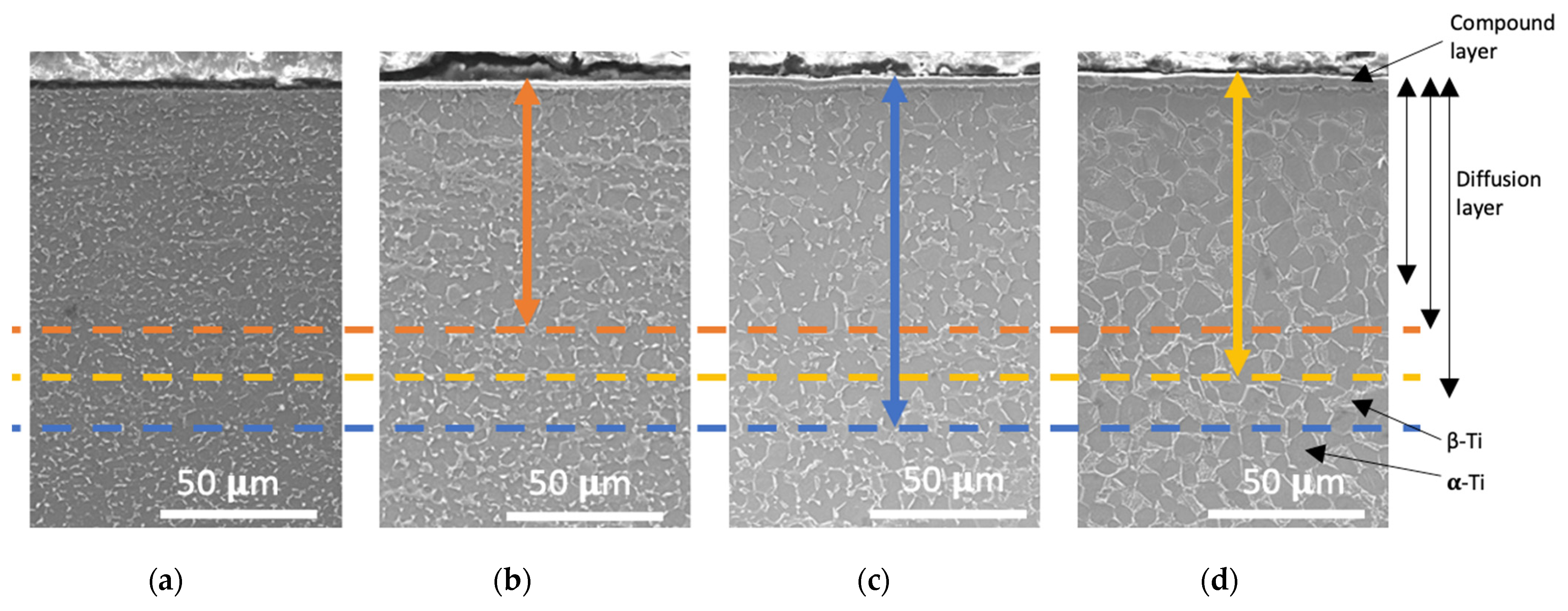
3.3. Microstructure Analysis

Normally, the material that passes through the plasma nitriding process generates two important layers: namely, the compound layer or layer on the top surface and the diffusion layer or layer under the compound layer. Subsequently, cross-sectional microstructure analysis was conducted for both parts of the diffusion layer and the compound layer.
The diffusion layer analysis or the analysis of the nitrogen diffused in Ti-6Al-4V started from the surface to the end of the layer. The objective was to identify the relationships between the nitrogen diffused, hardness, and residual compressive stress. The results generated from the diffusion layer analysis are shown in Figure 6. Normally, Ti-6Al-4V would have β-Ti thoroughly dissolved in α-Ti as a composition of the microstructure shown in the untreated Ti-6Al-4V and base metal layer. However, in the diffusion layer of the plasma-nitrided Ti-6Al-4V, the nitrogen that was dissolved in the Ti-6Al-4V structure reduced β-Ti in this layer [22,27,41]. Thus, to classify the depth of the diffusion layer, the distribution of β-Ti was used. Moreover, the higher nitrogen diffusion could reduce β-Ti in the layer. Therefore, the near-surface possibly had higher nitrogen diffusion, resulting in higher hardness and residual compressive stress, which was further studied and confirmed in other sections. The analysis of the depth from the surface to the end of the diffusion layer was concluded in Table 3. The depth of the diffusion layer from the surface to the end after the plasma-nitriding process with 750 °C for 5 h was approximately 78.3 μm. While increasing the temperature to 800 °C for 5 h, the depth from the surface to the end of the diffusion layer approximately increased to 98.6 μm. The reason for the increasing depth on the diffusion layer resulting from the increasing temperature was due to the increase in the nitrogen diffusion rate from higher energy [42,43]. Upon comparison between the different processing times, the result of the higher time of the plasma-nitriding process of 10 h at 750 °C showed a deeper level of depth from the surface to the end of the diffusion layer with a lower time at approximately 116.5 μm. This was considered the deepest finding in this research. The increasing time led to an increase in the number of diffusions of nitrogen into Ti-6Al-4V from layer to layer, which was a reason for the deeper level of the diffusion layer [16,44]. The depth from the surface to the end of the diffusion layer was possibly related to residual stress and cross-sectional hardness, which was further explained in other sections.
On the other hand, focusing on the compound layer in Figure 6, the pictures of the microstructure in the cross-section on the near-surface in different plasma-nitriding conditions are subsequently illustrated in Figure 7. The approximation of the compound layer thickness and α-case is concluded in Table 3. The compound layer on top of the surface contained a composition of δ-TiN and Ti2N, as confirmed in the phase identification section. The layers under the compound layer were an Al-rich layer and an α-case which were created when Ti and N were formed on the compound layer, [27,41]. However, the main focus of this research section was on the compound layer thickness and α-case as both properties could possibly reduce the bending fatigue strength due to high hardness with low toughness [22,23,24,25]. The lowest time and temperature of the plasma-nitriding condition at 750 °C for 5 h indicated the lowest compound layer thickness at 2.58 μm without an α-case. When increasing the times of the plasma-nitriding process to 10 h at 750 °C, the compound layer increased to 3.15 μm with a few α-case, which was 2.40 μm. The reason for the increasing compound layer and α-case was caused by a huge number of reactions of Ti and N upon the formation of a compound layer following an increase in time. Nevertheless, the largest thickness of the compound layer and α-case found in this research came from the highest temperature of the plasma-nitriding process at 800 °C for 5 h. The compound layer and α-case thickness of 4.06 μm and 5.31 μm were found in this plasma nitriding condition. The largest thickness found was generated from higher energy resulting from an increasing temperature which increased the reaction of the compound layer formed between Ti and N. The higher thickness of the compound layer and α-case could affect the surface hardness [22,45], which is further depicted in the surface hardness section. However, it is significantly noted that a higher compound layer and α-case thickness should be controlled, as explained in a reduction in the bending fatigue strength in the introduction.

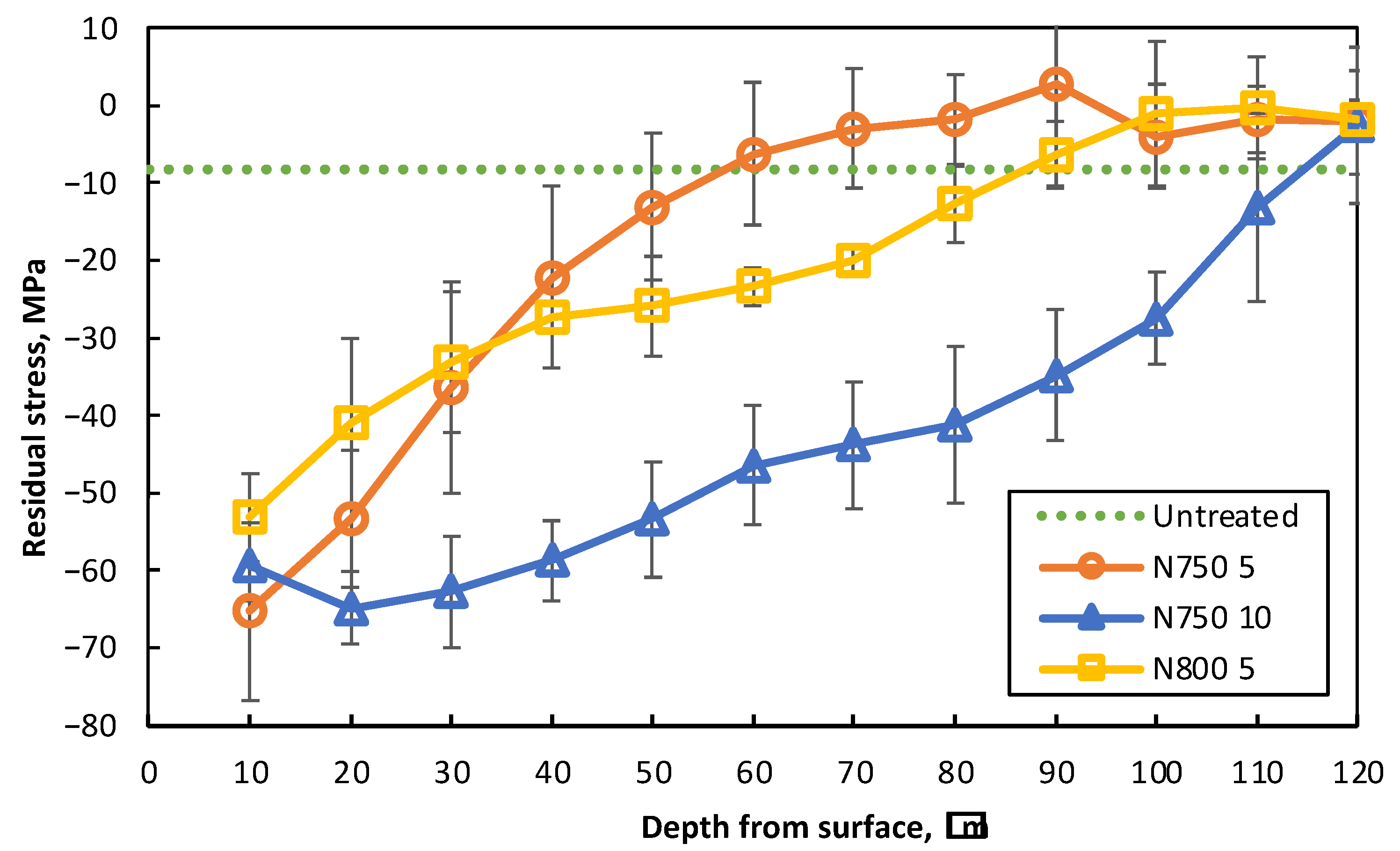
3.4. Residual Stress Analysis

After applying X-ray diffraction (XRD) to analyze the residual stress of Ti-6Al-4V with different plasma nitriding conditions, the result is accordingly shown in Figure 8. The measurement started at a 10 μm depth from the surface to analyze the residual stress from the diffusion layer without any effects of the residual stress in the compound layer. The untreated Ti-6Al-4V showed average residual stress at approximately −8.3 MPa due to metal forming. Meanwhile, upon different plasma-nitriding processes, the material showed residual compressive stress at the near surface between −53.2 and −65.3 MPa and gradually decreased to approximately 0 Mpa when the depth from the surface was increased. With the comparison of maximum residual compressive stress, the highest stated in this research was the lowest time and temperature condition, which was 750 °C for 5 h. The result found that the highest residual compressive stress was at −65.3 MPa of the maximum residual compressive stress. While under the increasing temperature condition of plasma nitriding with 800 °C for 5 h, the result showed the lowest of the maximum residual compressive stress at −53.2 MPa. The highest time of the plasma-nitriding process, which was 10 h at 750 °C, showed a slightly lower level of the maximum residual compressive stress than the lower processing time at −59.4 MPa. The lower level of the maximum residual compressive stress upon an increase in the processing temperature and time was caused by a release of residual stress from a high thermal that reduced the residual compressive stress and volume change during the treatment time, although higher nitrogen centration was confirmed by microstructure analysis [16,44]. On the other hand, upon the comparison of the residual compressive stress depth or the deepest level of residual compressive stress found from each condition, the plasma nitriding process under 750 °C for 5 h showed the lowest residual compressive stress depth at approximately 80 μm from the surface, while plasma nitriding at 800 °C for 5 h showed deeper levels of residual compressive stress depth up to 100 μm from the surface. The increase in the residual compressive stress depth when increasing the temperature could be explained by an increasing number of nitrogen diffusion, in which the diffused nitrogen from layer to layer resulted in greater and higher diffusion rates, as confirmed in cross-sectional microstructure analysis. Nevertheless, the highest residual compressive stress depth was also found under the conditions of plasma nitriding at 750 °C for 10 h at approximately 120 μm depth from the surface. The increasing residual compressive stress depth was caused by the greater diffusions of nitrogen from layer to layer, which was confirmed by the deepest diffusion layer depth from the surface to the end, as shown in Figure 6. The residual compressive stress depth corresponding to the depth of the diffusion layer in cross-sectional microstructure analysis, resulting from the surface to the end of the diffusion layer of each condition, confirmed the effect of nitrogen diffusion on generating residual compressive stress by the distortion of the titanium structure [16,17]. According to the bending stress with the highest tensile on the surface and gradually decreased depth from the surface, the application of residual compressive stress by nitriding would be sufficient to resist the tensile stress from bending stress to typically improve the bending fatigue strength of the material [45]. Thus, a deeper residual compressive stress with high values around the surface could be beneficial when applied to high-thickness material.

3.5. Hardness Analysis

The hardness analysis was divided into two parts, including the hardness on top of the surface to obtain the effects of the compound layer and cross-sectional hardness and to identify the hardness which was increased in the diffusion layer.
The result of the hardness on the top of the surface described in Figure 9 indicated that, after the plasma-nitriding process, the surface hardness was increased, due to the higher hardness of δ-TiN and Ti2N in the compound layer, including the α-case under the compound layer [22,46]. In addition, the indentations of all the plasma-nitrided Ti-6Al-4V were not found with any cracks on the edge or even after indentation. The process of plasma nitriding at 750 °C for 5 h increased the surface hardness of Ti-6Al-4V from 357 HV to 604 HV. The condition of increasing the treatment time to 10 h at 750 °C showed a higher surface hardness of 684 HV, and the highest surface hardness found in this research was 826 HV under the condition of plasma nitriding at 800 °C for 5 h. The result indicated that the level of the compound layer and α-case thickness was found at the highest level under conditions of 800 °C for 5 h, at a moderate surface hardness under conditions of 750 °C for 10 h, and at the lowest level under conditions of 750 °C for 5 h. It could be observed that the compound layer and α-case could increase the surface hardness of Ti-6Al-4V up to twice, which would subsequently reduce the toughness of the surface, resulting in the higher possibility of cracks on the surface which is considered a cause for reducing the capability of the bending fatigue strength [27].
The other result of hardness, including the cross-sectional hardness shown in Figure 10, described the hardness in each point depth starting from 10 μm in depth from the surface to neglect the effects of the compound layer. The result showed that the average cross-sectional hardness of untreated Ti-6Al-4V was approximately 357 HV. However, through the plasma nitriding process, an increase in the case depth hardness or depth of increase in the hardness in the cross-sectional approach was generated. The highest hardness was found at a 10 μm depth from the surface and gradually decreased to the normal hardness of Ti-6Al-4V when the depth from the surface was increased. The reason for increasing the hardness in the diffusion layer was generated by a hard slip of grain through the diffusion of nitrogen into the titanium grain [46]; thus, the higher nitrogen in the layer would have a higher hardness, as will be explained in this section. The result of the Ti-6Al-4V hardness at 10 μm depth from the surface applied under the lowest time and temperature conditions of plasma nitriding at 750 °C for 5 h showed an increase in the hardness to 528 HV with a case depth hardness of 80 μm. When increasing the treatment temperature to 800 °C for 5 h, the result revealed the highest hardness at 10 μm depth from the surface at 643 HV, the highest hardness found in this research, while the case depth hardness was deeper at lower temperatures at 100 μm. The highest treatment time of plasma nitriding under 750 °C for 10 h showed the deepest level of the case depth hardness, which was 120 μm, with the hardness at a 10 μm depth from the surface at 559 HV. When increasing the processing time and temperature, the nitrogen could be diffused from layer to layer and delivered into Ti-6Al-4V, which was greater than the result conducted under lower time and temperatures confirmed in the cross-sectional microstructure. This could increase a higher and deeper hardness than the lower processing time and temperature. However, the deepest level in the case depth hardness under the condition of plasma nitriding at 750 °C for 10 h showed a lower hardness than plasma nitriding at 800 °C for 5 h, which was a lower depth than the case depth hardness. This could be explained by the nitrogen concentration at each point of depth from the surface. The higher temperature could more effectively turn nitrogen to Ti-6Al-4V than the lower temperature, as confirmed in the cross-sectional microstructure analysis, which showed that the hardness would be increased. Nevertheless, due to the short treatment time, few layers of nitrogen would be diffused. However, the case depth hardness of each condition of the plasma nitriding condition corresponded to the depth from the surface to the end of the diffusion layer and residual compressive stress depth, which confirmed the effect of nitrogen diffusion on the increasing hardness by a harder slip of grain. It was noted that the higher cross-sectional hardness is one of the parameters that would possibly increase the strength of the material towards improving the bending fatigue strength [28,29].

4. Conclusions

The conclusion of the examination of the microstructure, residual stress, and hardness of Ti-6Al-4V after the plasma nitriding process with different times and temperatures is described as follows:
  • The plasma nitriding was able to generate residual compressive stress and increase hardness due to the diffusion of nitrogen into the material structure, including a changing surface morphology and roughness by creating a compound layer containing TiN and Ti2N on the surface.
  • The higher processing time and temperature of plasma nitriding would generate a bigger size of TiN and Ti2N, resulting in a higher roughness and thickness in the compound layer, which would affect an increase in higher surface hardness. Moreover, a higher time and temperature would generate deeper residual compressive stress depth and case depth hardness than the lower conditions due to the deeper diffusion of nitrogen. However, the maximum residual compressive stress would decrease corresponding to the increasing treatment time and temperature due to a release of residual stress.
  • The depths of the case depth hardness and residual compressive stress generated by plasma nitriding in different conditions corresponded to the depth from the surface to the end of the diffusion layer, which was confirmed by the effect of nitrogen diffusion on increasing strength.
The suggestion of this research for increasing the bending fatigue strength of Ti-6Al-4V by using the plasma nitriding process was to maintain the temperature lower than 800ᵒc to avoid the higher thickness of the compound layer. Low temperatures with a long processing time would be more effective in generating residual compressive stress and increasing the hardness in the depth while retaining a low compound layer thickness. However, the removal of the compound layer should be proceeded to ensure that no reduction in the bending fatigue strength applied from the compound layer occurs.

Author Contributions

Conceptualization, methodology, formal analysis, investigation, G.O., A.K., J.K. and K.K.; resources, A.K.; writing—original draft preparation, G.O.; writing—review and editing, G.O., A.K., J.K. and K.K., visualization, G.O.; supervision, A.K., J.K. and K.K.; project administration, A.K.; All authors have read and agreed to the published version of the manuscript.

Funding

This research was funded by the National Research Council of Thailand (NRCT) [grant numbers NRCT(G)REKM/116/2560], and a Scholarship for the Development of High-Quality Research Graduates in Science and Technology Petchra Pra Jom Klao Ph.D. Research Scholarship (KMUTT–NSTDA) from King Mongkut’s University of Technology Thonburi, grant number PHD/0054/2562.

Institutional Review Board Statement

Not applicable.

Informed Consent Statement

Not applicable.

Data Availability Statement

Not applicable.

Conflicts of Interest

The authors declare no conflict of interest.

References

  1. Gotman, I. Characteristics of Metals Used in Implants. J. Endourol. 1997, 11, 383–389. [Google Scholar] [CrossRef] [PubMed]
  2. Khan, M.A.; Williams, R.L.; Williams, D.F. The corrosion behaviour of Ti–6Al–4V, Ti–6Al–7Nb and Ti–13Nb–13Zr in protein solutions. Biomaterials 1999, 20, 631–637. [Google Scholar] [CrossRef] [PubMed]
  3. Navarro, M.; Michiardi, A.; Castaño, O.; Planell, J.A. Biomaterials in orthopaedics. J. R. Soc. Interface 2008, 5, 1137–1158. [Google Scholar] [CrossRef] [PubMed] [Green Version]
  4. Vu, N.B.; Nhung, T.; Dang, L.T.; Phi, L.; Thi-Thu Ho, N.; Pham, T.N.; Phan, T.P.; Pham, P.V. In vitro and in vivo biocompatibility of Ti-6Al-4V titanium alloy and UHMWPE polymer for total hip replacement. Biomed. Res. Ther. 2016, 3, 567–577. [Google Scholar] [CrossRef]
  5. Papynov, E.K.; Shichalin, O.O.; Belov, A.A.; Yu Buravlev, I.; Portnyagin, A.S.; Kozlov, A.G.; Gridasova, E.A.; Tananaev, I.G.; Sergienko, V.I. Ionizing radiation source-open type fabrication using additive technology and spark plasma sintering. Ceram. Int. 2022, in press. [Google Scholar] [CrossRef]
  6. Son, D.S.; Chang, S.H. The simulation of bone healing process of fractured tibia applied with composite bone plates according to the diaphyseal oblique angle and plate modulus. Compos. B Eng. 2013, 45, 1325–1335. [Google Scholar] [CrossRef]
  7. Antoniac, I.V.; Stoia, D.I.; Ghiban, B.; Tecu, C.; Miculescu, F.; Vigaru, C.; Saceleanu, V. Failure Analysis of a Humeral Shaft Locking Compression Plate—Surface Investigation and Simulation by Finite Element Method. Materials 2019, 12, 1128. [Google Scholar] [CrossRef] [Green Version]
  8. Agarwal, A.; Kodigudla, M.; Kelkar, A.; Jayaswal, D.; Goel, V.; Palepu, V. Towards a validated patient-specific computational modeling framework to identify failure regions in traditional growing rods in patients with early onset scoliosis. N. Am. Spine Soc. J. (NASSJ) 2021, 5, 100043. [Google Scholar] [CrossRef]
  9. Thapa, N.; Prayson, M.; Goswami, T. A failure study of a locking compression plate implant. Case Stud. Eng. Fail. Anal. 2015, 3, 68–72. [Google Scholar] [CrossRef] [Green Version]
  10. Banovetz, J.M.; Sharp, R.; Probe, R.; Anglen, J.O. Titanium Plate Fixation: A Review of Implant Failures. J. Orthop. Trauma 1996, 10, 389–394. [Google Scholar] [CrossRef]
  11. Aksakal, B.; Yildirim, Ö.S.; Gul, H. Metallurgical failure analysis of various implant materials used in orthopedic applications. J. Fail. Anal. Preven. 2004, 4, 17–23. [Google Scholar] [CrossRef]
  12. Yamanaka, K.; Mori, M.; Yamazaki, K.; Kumagai, R.; Doita, M.; Chiba, A. Analysis of the Fracture Mechanism of Ti-6Al-4V Alloy Rods That Failed Clinically After Spinal Instrumentation Surgery. Spine 2015, 40, E767–E773. [Google Scholar] [CrossRef] [PubMed]
  13. Niinomi, M.; Nakai, M. Titanium-Based Biomaterials for Preventing Stress Shielding between Implant Devices and Bone. Int. J. Biomater. 2011, 2011, 836587. [Google Scholar] [CrossRef] [PubMed] [Green Version]
  14. Dai, K. Rotational Utilization of Stress Shielding Effect of Implants. In Biomechanics and Biomaterials in Orthopedics; Poitout, D.G., Ed.; Springer: London, UK, 2004; pp. 208–215. [Google Scholar] [CrossRef]
  15. Liang, S. Review of the Design of Titanium Alloys with Low Elastic Modulus as Implant Materials. Adv. Eng. Mater. 2020, 22, 2000555. [Google Scholar] [CrossRef]
  16. Barrallier, L. Classical nitriding of heat treatable steel. In Thermochemical Surface Engineering of Steels; Mittemeijer, E.J., Somers, M.A.J., Eds.; Woodhead Publishing: Cambridge, UK, 2015; pp. 393–412. [Google Scholar] [CrossRef] [Green Version]
  17. Dalcin, R.L.; Oliveira, L.F.; Diehl, I.L.; Dias, V.W.; da Silva Rocha, A. Response of a DIN 18MnCrSiMo6-4 Continuous Cooling Bainitic Steel to Plasma Nitriding with a Nitrogen Rich Gas Composition. Mat. Res. 2020, 23, 20200036. [Google Scholar] [CrossRef]
  18. Winck, L.B.; Ferreira, J.L.A.; Araujo, J.A.; Manfrinato, M.D.; da Silva, C.R.M. Surface nitriding influence on the fatigue life behavior of ASTM A743 steel type CA6NM. Surf. Coat. Technol. 2013, 232, 844–850. [Google Scholar] [CrossRef]
  19. Kao, W.H.; Su, Y.L.; Horng, J.H.; Chang, C.Y. Tribological, electrochemical and biocompatibility properties of Ti6Al4V alloy produced by selective laser melting method and then processed using gas nitriding, CN or Ti-C:H coating treatments. Surf. Coat. Technol. 2018, 350, 172–187. [Google Scholar] [CrossRef]
  20. Samanta, A.; Rane, R.; Jhala, G.; Kundu, B.; Datta, S.; Ghosh, J.; Joseph, A.; Mukherjee, S.; Roy, S.; Mukhopadhyay, A.K. Biocompatibility and cyclic fatigue response of surface engineered Ti6Al4V femoral heads for hip-implant application. Ceram. Int. 2021, 47, 6905–6917. [Google Scholar] [CrossRef]
  21. Winter, K.-M.; Kalucki, J.; Koshel, D. Process technologies for thermochemical surface engineering. In Thermochemical Surface Engineering of Steels; Mittemeijer, E.J., Somers, M.A.J., Eds.; Woodhead Publishing: Cambridge, UK, 2015; pp. 141–206. [Google Scholar] [CrossRef]
  22. Edrisy, A.; Farokhzadeh, K. Plasma Nitriding of Titanium Alloys, In Plasma Science and Technology—Progress in Physical States and Chemical Reactions; IntechOpen: London, UK, 2016. [Google Scholar] [CrossRef] [Green Version]
  23. Unal, O.; Maleki, E.; Varol, R. Effect of severe shot peening and ultra-low temperature plasma nitriding on Ti-6Al-4V alloy. Vacuum 2018, 150, 69–78. [Google Scholar] [CrossRef]
  24. Mubarak Ali, M.; Ganesh Sundara Raman, S. Effect of Plasma Nitriding Environment and Time on Plain Fatigue and Fretting Fatigue Behavior of Ti–6Al–4V. Tribol. Lett. 2010, 38, 291–299. [Google Scholar] [CrossRef]
  25. Kikuchi, S.; Yoshida, S.; Ueno, A. Improvement of fatigue properties of Ti-6Al-4V alloy under four-point bending by low temperature nitriding. Int. J. Fatigue 2019, 120, 134–140. [Google Scholar] [CrossRef]
  26. De Castro, M.C.B.; Couto, A.A.; Almeida, G.F.C.; Massi, M.; de Lima, N.B.; da Silva Sobrinho, A.; Castagnet, M.; Xavier, G.L.; Oliveira, R.R. The Effect of Plasma Nitriding on the Fatigue Behavior of the Ti-6Al-4V Alloy. Materials 2019, 12, 520. [Google Scholar] [CrossRef] [PubMed] [Green Version]
  27. Farokhzadeh, K.; Edrisy, A. Fatigue improvement in low temperature plasma nitrided Ti–6Al–4V alloy. Mater. Sci. Eng. A 2015, 620, 435–444. [Google Scholar] [CrossRef]
  28. Morita, T.; Uehigashi, N.; Kagaya, C. Improvement of Fatigue Strength of Ti–6Al–4V Alloy by Hybrid Surface Treatment Composed of Plasma Nitriding and Fine-Particle Bombarding. Mater. Trans. 2013, 54, 1719–1724. [Google Scholar] [CrossRef] [Green Version]
  29. Morita, T.; Uehigashi, N.; Kagaya, C. Effect of Hybrid Surface Treatment Composed of Plasma Nitriding and Fine Particle Bombarding on Fatigue Strength of Ti–6Al–4V Alloy. Mater. Trans. 2013, 54, 22–27. [Google Scholar] [CrossRef] [Green Version]
  30. ASTM F136. Standard Specification for Wrought Titanium-6Aluminum-4Vanadium ELI (Extra Low Interstitial) Alloy for Surgical Implant Applications (UNS R56401); ASTM International: West Conshohocken, PA, USA, 2021. Available online: https://www.astm.org/Standards/F136.htm (accessed on 8 October 2021).
  31. Shivamurthy, R.C.; Kamaraj, M.; Nagarajan, R.; Shariff, S.M.; Padmanabham, G. Laser surface modification of steel for slurry erosion resistance in power plants. In Laser Surface Modification of Alloys for Corrosion and Erosion; Kwok, C.T., Ed.; Woodhead Publishing: Cambridge, UK, 2012; pp. 177–287. [Google Scholar] [CrossRef]
  32. Aghajani, H.; Behrangi, S. Plasma Nitriding of Steels. In Topics in Mining, Metallurgy and Materials Engineering; Bergmann, C.P., Ed.; Springer: Cham, Switzerland, 2017. [Google Scholar] [CrossRef]
  33. JIS B0601. Geometrical Product Specifications (GPS}-Surface texture: Profile method—Terms, definitions and surface texture parameters, Surface Roughness; Japanese Standards Association: Tokyo, Japan, 2001. [Google Scholar]
  34. Cullity, B.D.; Stock, S.R. Elements of X-ray Diffraction, 2nd ed.; Addison-Wesley Publishing Company Inc.: Boston, MA, USA, 1978. [Google Scholar]
  35. Hauk, V. Structural and Residual Stress Analysis by Nondestructive Methods, 1st ed.; Elsevier Science B.V.: Amsterdam, Netherlands, 1997. [Google Scholar] [CrossRef]
  36. ASTM E92. Standard Test Methods for Vickers Hardness and Knoop Hardness of Metallic Materials; ASTM International: West Conshohocken, Pennsylvania, USA, 2017. Available online: https://www.astm.org/Standards/E92.htm (accessed on 24 June 2019).
  37. Bhavsar, V.N.; Jha, J.S.; Jhala, G.; Joseph, A.; Mishra, S.; Tewari, A. Characterization of Ti6Al4V alloy modified by plasma nitriding process. In Proceedings of the ASME 2017 Gas Turbine India Conference GTINDIA, Mumbai, India, 7–8 December 2017; pp. 1–5. [Google Scholar] [CrossRef]
  38. Hosseini, S.R.; Ahmadi, A. Evaluation of the effects of plasma nitriding temperature and time on the characterisation of Ti 6Al 4V alloy. Vacuum 2013, 87, 30–39. [Google Scholar] [CrossRef]
  39. Morgiel, J.; Maj, Ł.; Szymkiewicz, K.; Pomorska, M.; Ozga, P.; Toboła, D.; Tarnowski, M.; Wierzchoń, T. Surface roughening of Ti-6Al-7Nb alloy plasma nitrided at cathode potential. Appl. Surf. Sci. 2022, 574, 151639. [Google Scholar] [CrossRef]
  40. Lee, D.B.; Pohrelyuk, I.; Yaskiv, O.; Lee, J.C. Gas nitriding and subsequent oxidation of Ti-6Al-4V alloys. Nanoscale Res. Lett. 2012, 7, 21. [Google Scholar] [CrossRef] [Green Version]
  41. Lee, D.B.; Kim, M.J.; Chen, L.; Hwan Bak, S.; Yaskiv, O.; Pohrelyuk, I.; Fedirko, V. Oxidation of nitride layers formed on Ti-6Al-4V alloys by gas nitriding. Met. Mater. Int. 2011, 17, 471–477. [Google Scholar] [CrossRef]
  42. Ponticaud, C.; Guillou, A.; Lefort, P. Direct gaseous nitridation of the Ti–6Al–4V alloy by nitrogen. Phys. Chem. Chem. Phys. 2000, 2, 1709–1715. [Google Scholar] [CrossRef]
  43. Fouquet, V.; Pichon, L.; Straboni, A.; Drouet, M. Nitridation of Ti6Al4V by PBII: Study of the nitrogen diffusion and of the nitride growth mechanism. Surf. Coat. Technol. 2004, 186, 34–39. [Google Scholar] [CrossRef]
  44. Jegou, S.; Barrallier, L.; Kubler, R.; Somers, M.A.J. Evolution of residual stress in the diffusion zone of a model Fe-Cr-C alloy during nitriding. HTM—J. Heat Treat. Mater. 2013, 6, 135–142. [Google Scholar] [CrossRef]
  45. Jing, J.N.; Dong, L.H.; Wang, H.D.; Jin, G. Influences of vacuum ion-nitriding on bending fatigue behaviors of 42CrMo4 steel: Experiment verification, numerical analysis and statistical approach. Int. J. Fatigue 2021, 145, 106104. [Google Scholar] [CrossRef]
  46. Yildiz, F.; Yetim, A.F.; Alsaran, A.; Çelik, A. Plasma nitriding behavior of Ti6Al4V orthopedic alloy. Surf. Coat. Technol. 2008, 202, 2471–2476. [Google Scholar] [CrossRef]
Figure 1. Results of Ti6Al4V surface after different plasma nitriding conditions applied. (a) Untreated; (b) N750 5; (c) N750 10; (d) N800 5.
Coatings 12 01932 g001
Figure 2. Surfaces of Ti6Al4V by optical microscope after different plasma nitriding conditions. (a) Untreated; (b) N750 5; (c) N750 10; (d) N800 5.
Coatings 12 01932 g002
Figure 3. Surfaces of Ti6Al4V by scanning electron microscope after different plasma nitriding conditions (a) Untreated; (b) N750 5; (c) N750 10; (d) N800 5.
Coatings 12 01932 g003
Figure 4. Surface roughness of Ti6Al4V after different plasma nitriding conditions. (a) The arithmetical mean roughness (Ra); (b) ten-point mean roughness.
Coatings 12 01932 g004
Figure 5. XRD patterns of Ti6Al4V after different plasma nitriding conditions (a) Untreated; (b) N750 5; (c) N750 10; (d) N800 5.
Coatings 12 01932 g005
Figure 6. Microstructures in cross section of Ti6Al4V after different plasma nitriding conditions. (a) Untreated; (b) N750 5; (c) N750 10; (d) N800 5.
Coatings 12 01932 g006
Figure 7. Microstructures in cross section on near surface of Ti6Al4V after different plasma nitriding conditions (a) N750 5; (b) N750 10; (c) N800 5.
Coatings 12 01932 g007
Figure 8. Residual stress of Ti6Al4V after different plasma nitriding conditions.
Coatings 12 01932 g008
Figure 9. Surface hardness of Ti6Al4V after different plasma nitriding conditions.
Coatings 12 01932 g009
Figure 10. Cross-sectional hardness of Ti6Al4V after different plasma nitriding conditions.
Coatings 12 01932 g010
Table 1. Chemical compositions of material in wt.%.
TiAlVFeCNOHOther
Remainder6.114.050.1650.0090.010.110.001<0.1
Table 2. Conditions of plasma nitriding.
Code NameTemperature °CTime
Untreated--
N750 5750 °C5 h
N750 10750 °C10 h
N800 5800 °C5 h
Table 3. Microstructure analysis of plasma nitriding.
Code NameDiffusion Layer
Depth from Surface
Compound Layer
Thickness
α-Case Thickness
N750 578.3 μm2.58 μm-
N750 10116.5 μm3.15 μm2.40 μm
N800 598.6 μm4.06 μm5.31 μm
Publisher’s Note: MDPI stays neutral with regard to jurisdictional claims in published maps and institutional affiliations.

