Article

Effect of Nitrogen Flow Rate on Microstructure and Optical Properties of Ta2O5 Coatings

1
School of Mechatronics Engineering, Henan University of Science and Technology, Luoyang 471003, China
2
Henan Key Laboratory for Machinery Design and Transmission System, Luoyang 471003, China
3
Longmen Laboratory, Luoyang 471000, China
*
Author to whom correspondence should be addressed.
Coatings 2022, 12(11), 1745; https://doi.org/10.3390/coatings12111745
Submission received: 21 October 2022 / Revised: 9 November 2022 / Accepted: 11 November 2022 / Published: 14 November 2022
(This article belongs to the Topic Surface Engineered Materials)

Abstract

:
Ta2O5 coatings were prepared on highly transparent quartz glass and silicon wafer substrates using RF magnetron sputtering technology. Different flow rates (10%, 15%, and 20%) of N2 were introduced during the sputtering process while keeping the total sputtering gas flow rate constant at 40 sccm. The effects of N2 flow rate on the phase structure, micro-morphology, elemental composition, and optical properties of Ta2O5 coatings were investigated. The coatings were characterized by X-ray diffraction (XRD), X-ray photoelectron spectroscopy (XPS), scanning electron microscopy (SEM), atomic force microscopy (AFM), electron energy spectroscopy (EDS), and spectrophotometry. The results show that the phase composition of the coating is an amorphous structure when the sputtering gases are pure argon and nitrogen-argon mixed gases, respectively. The coating after the passage of N2 is mainly composed of Ta, N, and O, which confirms that the deposited coating is a composite coating of Ta oxide and nitride. The EDS spectrum indicates that the ratio of O to Ta atoms in the composite coating is greater than the stoichiometric value of 2.5. It may be related to the deposition rate of Ta atoms during the preparation process. The optical properties show that the average transmittance of the composite coating is greater than 75% and the maximum light transmission is 78.03%. The transmittance in the visible range of Ta2O5 coatings prepared under nitrogen-argon mixed gas sputtering conditions is greater than that of those prepared under pure argon sputtering conditions. Finally, the coatings optical direct band gap Edg and indirect band gap Eig are obtained.

1. Introduction

With the rapid development of industrialization, modernization, and intellectualization, the demand for electrical energy is also rising dramatically [1]. Because of its renewable nature, solar power has become an alternative energy source widely used in human life and industry. Solar power is considered to have great potential in the power industry and has become a hot spot for domestic and international attention in recent years [2]. Because of the high transmittance characteristics of glass, it is often used as a cover plate to protect the battery components from harsh environments, such as dust and rain in solar battery components [3,4,5]. It is an indispensable part of solar power generation equipment. However, the actual environment is not friendly to solar cell cover modules. With abundant solar energy and poor land resources in northwest China, it becomes the optimal choice for building large PV power plant areas [6]. However, the harsh atmospheric environment in the region leads to the accumulation of gravel and dust particles on the surface of the glass cover, causing wear and tear that also reduces light transmission and thus affects the photoelectric conversion efficiency [7,8].
In the aerospace sector, solar power is the primary energy provider for the proper functioning of aerospace equipment. As the main detection tool of the lunar exploration project, solar power generation is especially important to ensure the normal operation of the rover. The lunar surface environment is complex, covering solar wind (hot electrons), solar UV, photoelectrons, plasma particles in the Earth’s magnetosphere, lunar dust, vacuum, and high and low temperatures [9]. These unknown factors bring many security risks to the lunar exploration project. Among them, the lunar dust is the biggest challenge facing the lunar exploration project. Because of the strong adhesion and electrostatic properties of moon dust, when deposited on the surface of solar photovoltaic cells, incident light will undergo transmission, reflection, and scattering phenomena, resulting in changes in the spectrum incident on the solar cells and reducing the photoelectric conversion rate.
It has been shown that applying a special functional coating on the surface of the solar cell glass cover can significantly improve photovoltaic conversion [10]. Due to the good optical properties, chemical stability [11], and high refractive index in the visible and near-infrared regions [12,13]. Ta2O5 coatings have been widely used as high-performance materials in semiconductors [14], data storage systems, and optical devices [15,16]. In addition to the above optical properties, Ta2O5 coatings also have mechanical properties, such as good wear resistance [17] and high hardness [18], which can be used as protective coatings. In recent years, transition metal nitride materials have attracted much attention because of their high hardness, oxidation resistance, stability, and their high wear resistance [19]. Riekkinen et al. [20] found that high-quality amorphous Ta metal nitride coatings can be prepared by controlling the N2 flow rate. Based on the excellent chemical and physical properties of transition metal oxides and nitrides, tantalum oxide and nitride composite coatings were designed.
In this study, tantalum metal oxide and nitride composite coatings were prepared by RF magnetron sputtering technology. The substrates were Quartz glass and silicon wafer, with Ta2O5 as the target, keeping the power at 140 W constant during sputtering. The prepared composite coating should have high light transmission characteristics without affecting the photoelectric conversion efficiency of the solar cell. The effect of N2 flow rate on the structure, element composition, chemical state, microstructure, and optical properties of composite coatings was studied.

2. Materials and Methods

The Ta2O5 coating was prepared by a JGP045CA RF sputtering system. The substrates are highly transparent quartz glass (10 mm × 10 mm × 2 mm) and a N<111> type silicon wafer (7 mm × 7 mm × 0.5 mm). The samples were ultrasonically cleaned with acetone, anhydrous ethanol, and deionized water for 15 min with the SCIENTZ-450 equipment (Ningbo, China) before deposition, dried with compressed air, and prepared for use. The total gas flow rate for deposition was kept constant at 40 sccm (10%, 15%, and 20% for N2/(N2 + Ar)) in the experiment, respectively). The target material is Ta2O5 of 99.99% purity (φ30 × 3 mm, Beijing Goodwill Metal Technology Development Co., Ltd., Beijing, China). The deposition temperature was room temperature, the sputtering power was 140 W, and the substrate rotation speed was 10 rpm (no negative bias). A clean target surface is obtained by glow discharge pre-sputtering for 10 min before deposition, and the deposition time is 45 min.
The microstructure of Ta2O5 thin films was analyzed by X-ray diffraction (XRD-Max2500, Rigaku, Japan) at a scanning angle of 5° under CuKa radiation of 50 kV and 150 mA. High-resolution spectra of Ta2O5 thin films were obtained by X-ray photoelectron spectroscopy (XPS, ESCALAB 250 Xi, Thermo Fischer, Waltham, MA, USA). The excitation source is Al kα ray (hv = 1486.6 eV) with a step length of 0.1 ev. The purpose is to analyze the ratio of tantalum to oxygen and nitrogen content in the film and the bonding state of the elements. The surface and cross-sectional morphology of the coating were obtained using a scanning electron microscope (SEM, Zeiss Sigma 300, Carl Zeiss, Jena, Germany), and the film deposition thickness was measured. Coating surface morphology and surface roughness (Ra) were obtained using an atomic force microscope (AFM, Bruker Dimension Icon, Billerica, MA, USA). Using a UV-Vis spectrophotometer (Shimadzu UV2700, Shimadzu, Kyoto, Japan), the transmission spectrum of the coating is obtained at a step of 0.5 nm in the visible wavelength range of 220–850 nm.

3. Results

Figure 1 shows that the XRD patterns of Ta2O5 coatings were deposited under different flow rates of N2 and Ar. XRD was used to analyze the phase structure of the Ta metal composite coating deposited on the Si substrate. It can be seen from Figure 1 that the coatings are amorphous when the sputtering gas conditions are 40 sccm Ar, 36 sccmAr-4 sccm N2,34 sccm Ar-6 sccm N2, and 32 sccm Ar-8 sccm N2, respectively. When the scanning angle 2θ is between 20°–40° gradually becomes flatter and wider, which is consistent with the results of Tsukimoto [21] and Chen et al. [22]. When a large number of Ta atoms are released from the target, they are freely mixed with argon ion radicals and nitrogen ions in the chamber. One part of the Ta atom recombines with the oxygen atom to form tantalum metal oxide, and the other part combines with the nitrogen atom to form tantalum metal nitride. As a result, the dynamic energy of the Ta metal particles reaching the substrate is reduced, and the crystal structure cannot be formed by orderly arranging the particle positions [23], so the prepared coating has an amorphous structure.
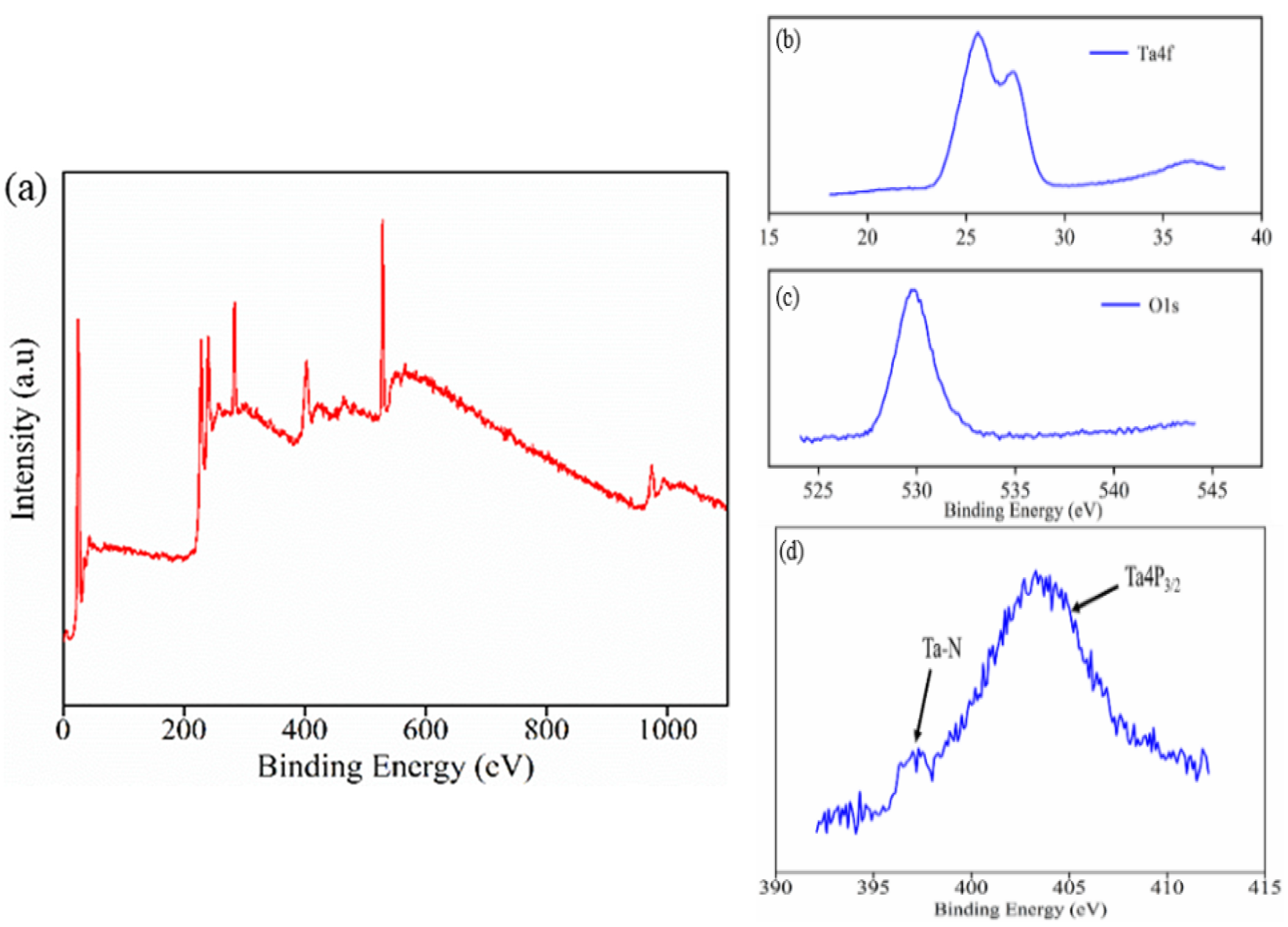
In order to obtain the elemental composition and chemical valence of the deposited coatings, the coating samples prepared at a sputtering gas flow rate of 34 sccm Ar-6 sccmN2 were characterized by XPS analysis. Figure 2 shows the XPS spectra of a Ta2O5 coating prepared at 34 sccm Ar-6 sccm N2 sputtering power of 140 W. The binding energy of all elements was corrected using the C1s = 284.8 eV signal as a binding energy reference. As shown in Figure 2, it is shown that a double peak in the Ta4f spectrum. The binding energies are 25.8 eV and 27.6 eV, corresponding to Ta4f7/2 and Ta4f5/2 orbitals, respectively, and are similar to the chemical state of Ta in the target material Ta2O5. Two low-binding-energy peaks, Ta4f7/2 = 23.2 eV and Ta4f5/2 = 24.6 eV, appeared after convolution fitting of the XPS spectra of Ta metal, which is consistent with the binding energy of Ta in TaN. It is indicated that the prepared coating samples are mainly composed of Ta metal oxide Ta2O5 and Ta metal nitride TaN. It is further verified that the coating sample prepared under this process condition is a Ta metal composite coating.
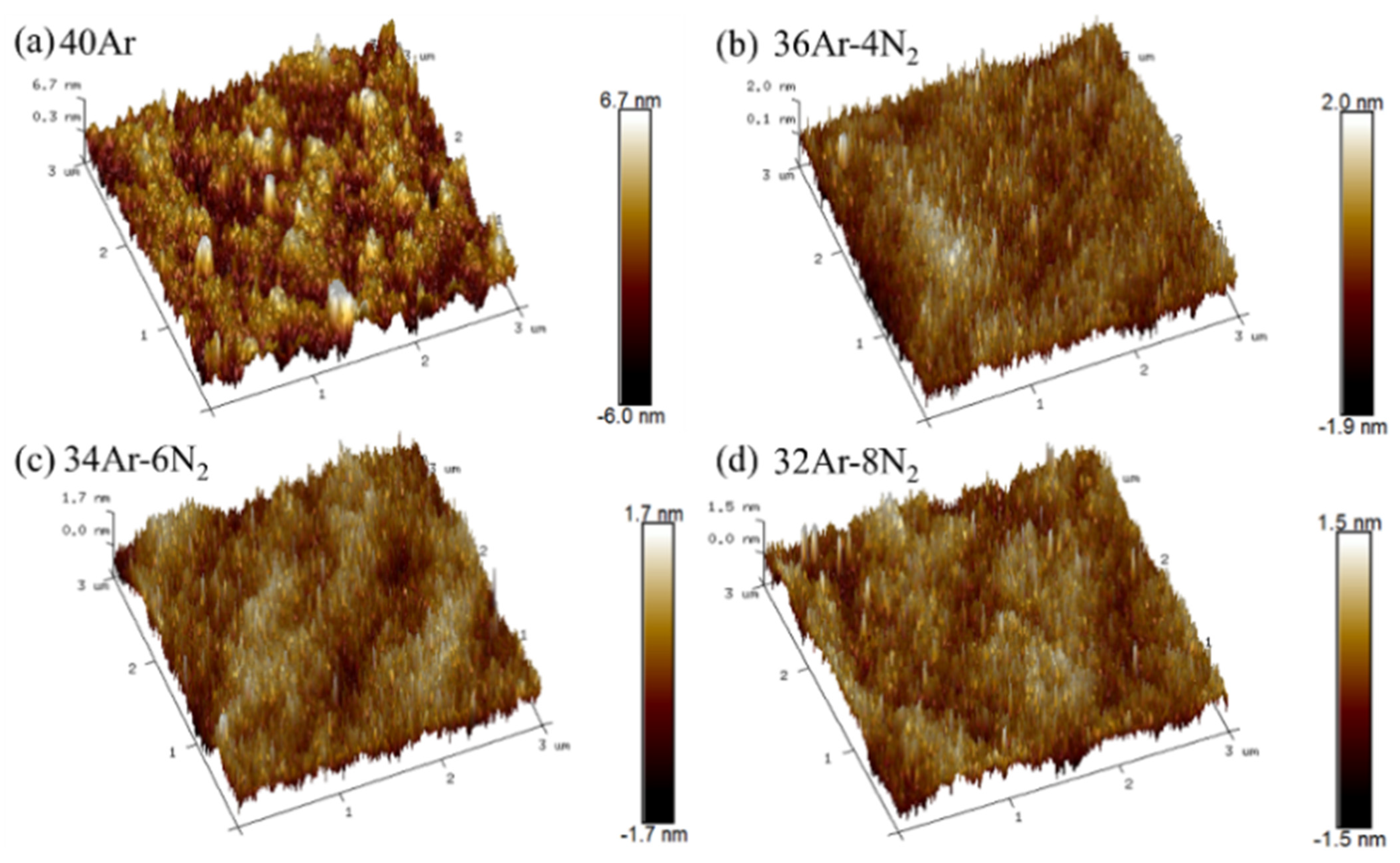
Figure 3 shows the surface and cross-section morphology of a Ta2O5 coating prepared under different N2 and Ar gas flow rates at a sputtering power of 140 W. It can be seen from Figure 3 that different nitrogen-argon gas flow ratios have a significant effect on the surface morphology of the prepared Ta2O5 coating samples. It can be seen that the surface of the composite coatings prepared with 40 sccm Ar, 36 sccm Ar-4 sccm N2, and 34 sccm Ar-6 sccm N2 is rough, and there is a large area of particle agglomeration. When the sputtering gas is 32 sccm Ar-8 sccm N2, the surface of the composite coating is smooth, and only a few particles agglomerate. Figure 4 shows the AFM images of Ta2O5 films deposited at different N2 and Ar flow and power rates of 140 W. It can be seen that the coating surface is smooth and uniform. The average roughness of the coatings was 1.14 nm, 0.429 nm, 0.382 nm, and 0.347 nm, respectively. It can be seen from the cross-sectional morphology of the coating that the sputtered particles of the deposited composite coating are uniformly accumulated. When the sputtering gas is 36 sccm Ar-4 sccm N2 and 32 sccmAr-8 sccm N2, slight cracks appear in the cross-sectional morphology of the coatings. Cracks may be caused by the silicon wafer during the fracture process. When the sputtering gas is 40 sccm Ar, 34 sccm Ar-6 sccm N2, and 32 sccm Ar-8 sccm N2, respectively, the cross-section morphology sputtered particles are closely packed.
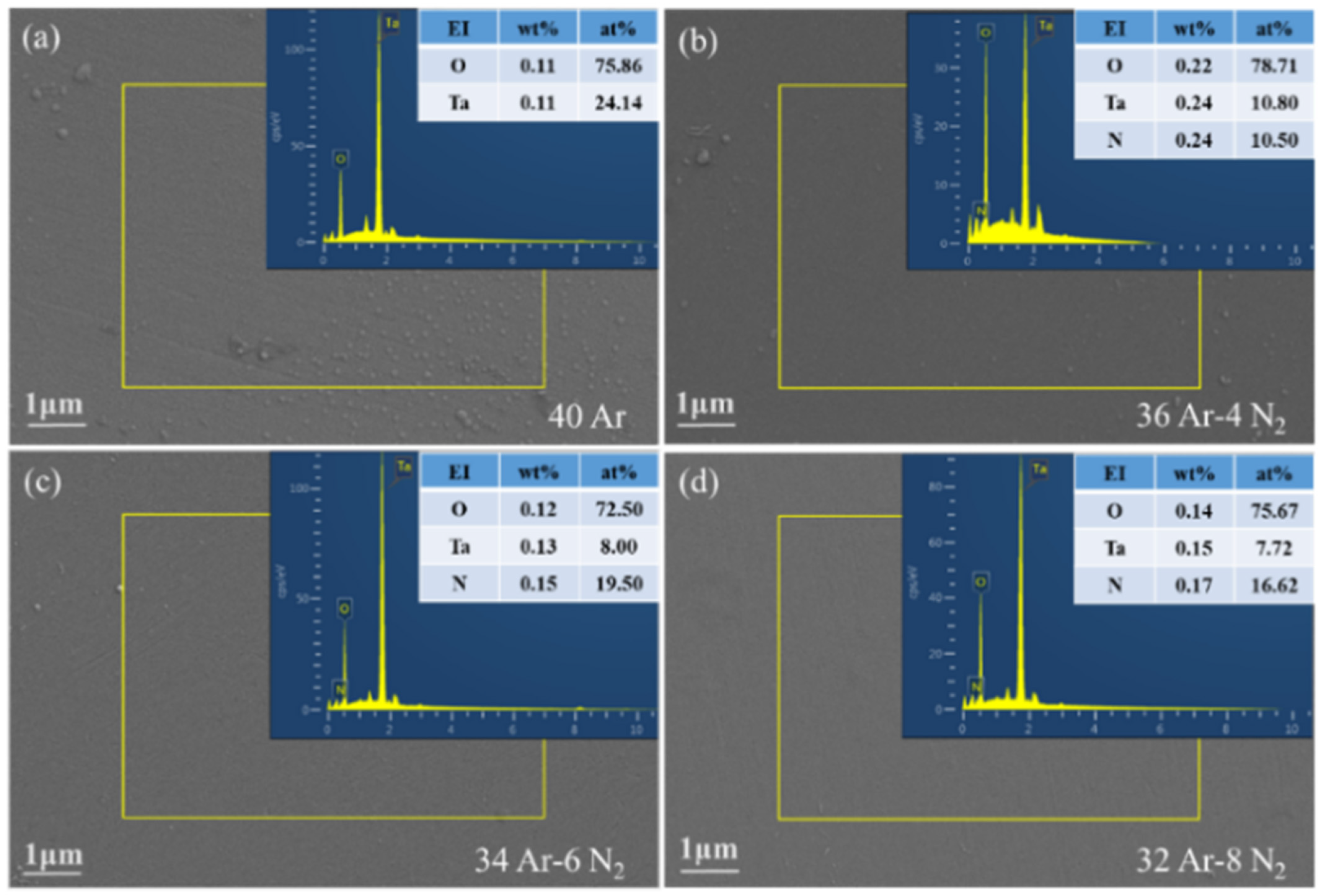
Figure 5 shows the surface EDS energy spectra of Ta2O5 coating samples prepared with different N2 and Ar gas flow rates when the sputtering power is 140 W. It can be seen from Figure 5 that the main component elements of the coating samples include Ta, O, and N. It was fully demonstrated that the prepared coating samples are oxides and nitrides of the metal Ta. From the proportion of the atomic content in Figure 5a, it is found that the atomic ratio of O to Ta in the Ta2O5 coating prepared under pure argon sputtering is greater than the stoichiometric ratio of 2.5. Analysis of the data in Figure 5b,d shows that when the sputtering gas is 36 sccm Ar-4 sccm N2,34 sccm Ar-6 sccm N2, and 32 sccm Ar-8 sccm N2, the ratio of O and Ta atoms in the coating is still greater than the stoichiometric ratio of 2.5. According to the chemical formula of Ta2O5, O/Ta is 2.5, and the test results of coating samples are greater than this ratio. Analysis of the reasons that argon ions bombard Ta2O5 on the target surface under the action of the magnetic field. After Ta atoms and O atoms obtain kinetic energy, they collide with each other under the action of the magnetic field, recombine, and deposit on the substrate surface. The deposition process is a bottom-up movement of ions deposited on the substrate surface within the sputtering chamber. Because the mass of the Ta atom is greater than that of the O atom, its rising rate is lower than that of the O atom. Some Ta atoms cannot reach the substrate surface and recombine with O atoms without sufficient kinetic energy. The ratio of O to Ta atoms in the coating sample is greater than the stoichiometric ratio. Further analysis of the data in Figure 5b,d shows that the content of Ta atoms decreases gradually from 10.80% to 7.72% with the increase in the N2 flow rate. This situation is mainly due to the sputtering gas total flow (40 sccm) remaining unchanged, the N2 flow ratio increasing, as the working gas Ar flow decreases, so that the number of ions bombarding the target reduces, resulting in a decrease in the Ta atom content. On the contrary, the content of N atoms increased from 10.50% to 19.50%, and then decreased to 16.62%, which was a process of increasing first and then decreasing. This may be due to the uneven distribution of N atom content in the selected coating area during EDS scanning.
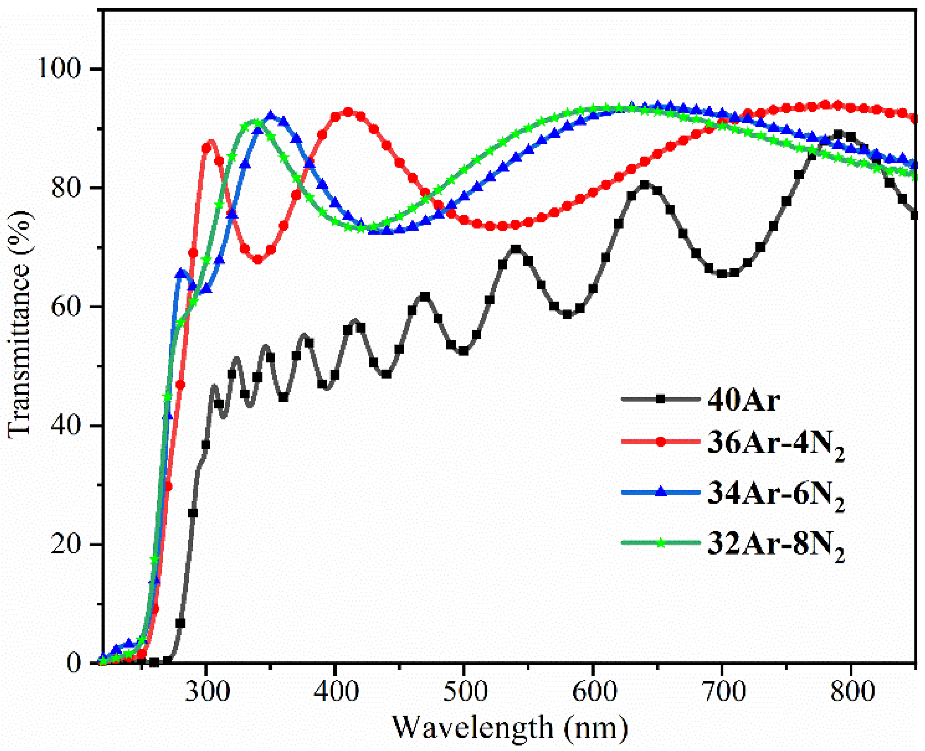
Figure 6 shows the transmittance curve of a Ta2O5 coating in the visible wavelength range when the sputtering gas is a mixture of nitrogen and argon. The average transmittance of Ta2O5 coatings prepared under pure argon sputtering conditions was 57.36% in the visible light (wavelength 220 nm–850 nm) range. The transmittance at wavelength 600 nm is 50%–60%, which is less than the theoretical value of 75%. This situation may be related to the contamination caused by other metal residues in the sputtering chamber of the experimental equipment. When the sputtering gases were 36 sccm Ar-4 sccm N2, 34 sccm Ar-6 sccm N2, and 32 sccm Ar-8 sccm N2, the average transmittance of the coating samples was 76.56%, 77.79%, and 78.03%, respectively. The transmittance of the coatings prepared under the nitrogen-argon mixture sputtering conditions was higher than the average transmittance of the coatings prepared under the pure argon sputtering conditions. In the study of the optical properties of thin films, the absorption coefficients of the films are usually studied to reflect the light transmission of the coatings. The absorption coefficients of the coatings prepared by sputtering were obtained by the envelope method and were 4.34 × 10⁻³, 2.35 × 10⁻³, 2.23 × 10⁻³, and 2.17 × 10⁻³ at a wavelength of 600 nm, respectively, which tended to decrease with the decrease of the argon flow rate [24,25]. Because the working principle of RF magnetron sputtering technology is argon ion bombardment, the transmittance curve of the coating sample can be deduced by comparing the transmittance curve of the coating sample. The transmittance of the coating increases with the decrease in argon gas flow rate. The reduced number of argon ions bombarding the target is due to the reduced sputtering gas flow. As the sputtering gas flow rate decreases, this results in a decrease in the number of argon ions bombarding the target. The coating deposited on the substrate during the same sputtering time becomes thinner (consistent with the changing trend of the cross-sectional thickness of the coating in Figure 3), which increases the transmittance of the coating in the visible light range. In the wavelength range below 300 nm, the coatings’ transmittance decreased significantly. The transmittance of the coatings increases rapidly when the wavelength is over 300 nm. This phenomenon is related to the large absorption of light caused by the energy gap transition of Ta2O5 [26]. The peaks and troughs on the transmittance curve are related to the interference effect [27]. Within a fixed wavelength range, the number of peaks and troughs depends on the optical thickness of the coatings (physical thickness multiplied by refractive index). The more peaks and troughs on the spectral curve indicate the thicker the optical thickness of the coatings, reflecting the thicker the physical thickness of the coatings [28]. The peaks and troughs on the transmittance curve of the coating in Figure 6 decrease with the increase in the N2 flow rate, indicating that the physical thickness of the coating is thinner, which is consistent with the changing trend of the cross-sectional thickness of the coating in Figure 3.
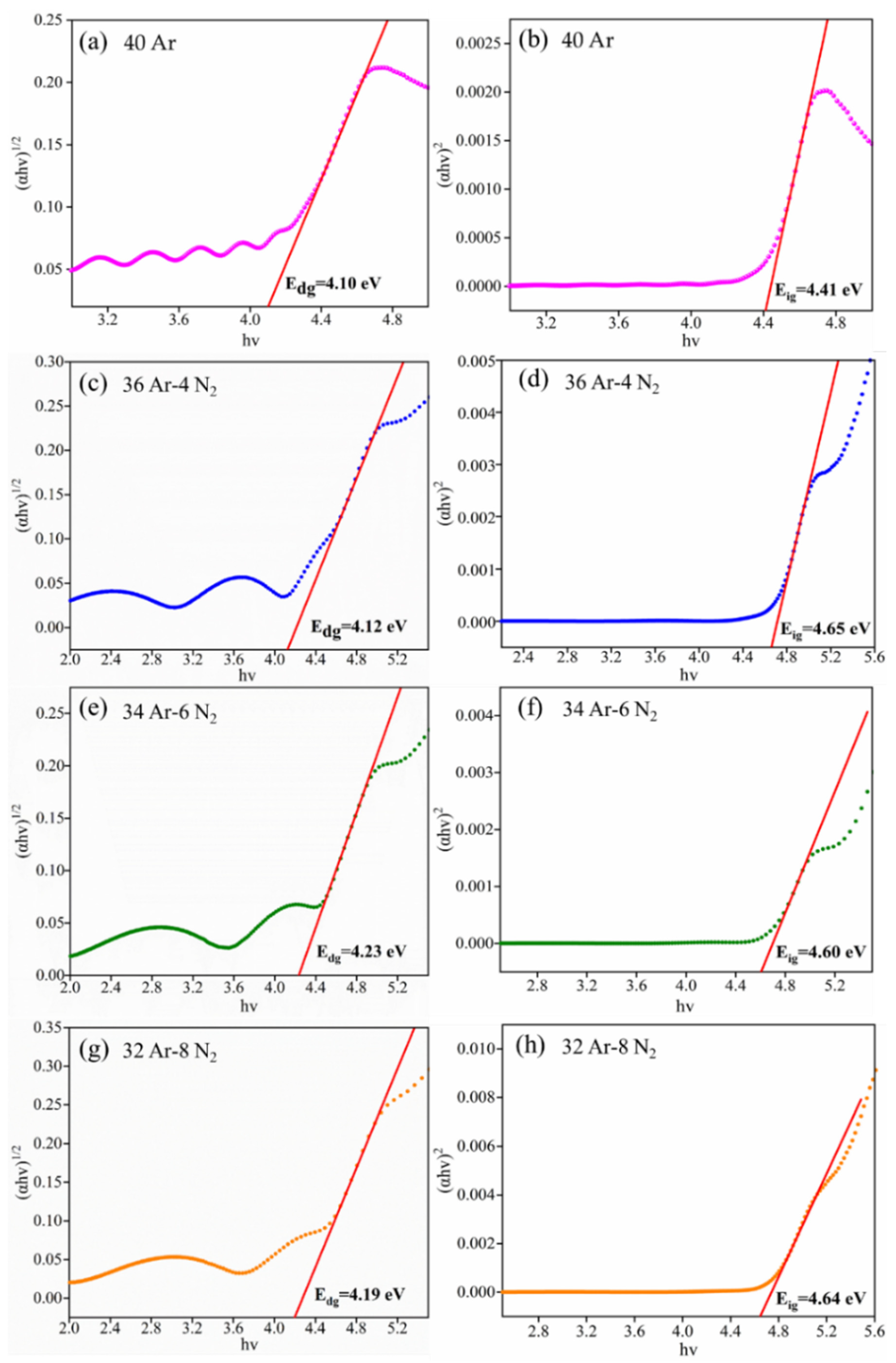
The optical band gap of Ta2O5 coatings prepared at different N2 and Ar gas flow rates is shown in Figure 7. The optical band gaps of the coatings were obtained from the Tauc plot [29]. The optical direct band gaps (Edg) of the Ta2O5 coatings prepared with sputtering gas flow rates of 40 sccm Ar, 36 sccm Ar-4 sccm N2, 34 sccm Ar-6 sccm N2, and 32 sccm Ar-8 sccm N2 were 4.10 eV, 4.12 eV, 4.23 eV, and 4.19 eV, respectively, as shown in Figure 7a,c,e, and g. The optical indirect band gaps (Eig) of Ta2O5 coating are 4.41 eV, 4.65 eV, 4.60 eV, and 4.64 eV, respectively, as shown in Figure 7b,d,f, and h. The obtained direct band gap values are very close to the band gap values of Ta2O5 coatings prepared by ion beam sputtering deposition and electron beam evaporation techniques [30,31]. Comparing the direct bandgap (Edg) and indirect bandgap (Eig) of the coatings, it was found that the values of the optical bandgap of the coatings prepared by passing N2 were slightly larger than those of the coatings prepared by pure Ar, indicating that the gas flow had some influence on the optical bandgap of the coatings.

4. Conclusions

(1) When the sputtering gas is pure Ar gas (40 sccm) or a nitrogen-argon mixture (36 sccm Ar-4 sccm N2, 34 sccm Ar-6 sccm N2, and 32 sccm Ar-8 sccm N2), the Ta2O5 coatings are all amorphous in structure. The broadening of the coating diffraction peaks is related to the recombination of Ta, N, and O atoms.
(2) The surface of the coatings is smooth, mainly composed of Ta, N, and O three elements. It is confirmed that the sample prepared under mixed sputtering gas conditions is a mixed coating of Ta2O5 and TaN.
(3) The optical test results show that when the Ta2O5 is on target, the transmittance of the coatings prepared under the condition of nitrogen-argon mixed gas sputtering is greater than that of the coatings were prepared under the condition of pure argon, with the maximum transmittance reaching 78.03%. The direct and indirect band gaps of the coating are between 4.10 eV–4.23 eV and 4.4 eV–4.65 eV, respectively.
Summary of each parameter for coating samples with different gas flow is presented in Table A1.

Author Contributions

Methodology, R.C.; Writing—review, and editing, H.C. and H.L.; Visualization, Y.X. All authors have read and agreed to the published version of the manuscript.

Funding

This research was funded by the National Key R&D Program of China (Grant No. 2021YFB3400401) and the National Defense Industrial Technology Development Program (Grant No. JCKY2018419C101).

Institutional Review Board Statement

Not applicable.

Informed Consent Statement

Not applicable.

Data Availability Statement

Not applicable.

Conflicts of Interest

The authors declare no conflict of interest.

Appendix A

Table A1. Summary table of each parameter of the coating samples.
ParametersGas Flow (sccm)
40 Ar36 Ar-4 N234 Ar-6 N232 Ar-8 N2
Coating thickness (nm)685.4437.6433.8337.8
Average roughness (nm)1.1400.4290.3820.347
EDS (at%)O75.8678.7172.5075.67
Ta24.1410.808.007.72
N-10.5019.5016.62
Average
transmittance (%)
57.3676.5677.7978.03
Optical band gap (eV)Edg4.104.124.234.19
Eig4.414.654.604.64
Absorption coefficient (k) l = 600 nm4.34 × 10−32.35 × 10−32.23 × 10−32.17 × 10⁻³

References

  1. Das, U.K.; Tey, K.S.; Seyedmahmoudian, M.; Mekhilef, S.; Idris, M.Y.I.; Van Deventer, W.; Horan, B.; Stojcevski, A. Forecasting of photovoltaic power generation and model optimization: A review. Renew. Sustain. Energy Rev. 2018, 81, 912–928. [Google Scholar] [CrossRef]
  2. Comello, S.; Reichelstein, S.; Sahoo, A. The road ahead for solar PV power. Renew. Sustain. Energy Rev. 2018, 92, 744–756. [Google Scholar] [CrossRef]
  3. Yilbas, B.S.; Ali, H.; Khaled, M.M.; Al-Aqeeli, N.; Abu-Dheir, N.; Varanasi, K.K. Influence of dust and mud on the optical, chemical and mechanical properties of a pv protective glass. Sci. Rep. 2015, 5, 15833. [Google Scholar] [CrossRef] [PubMed] [Green Version]
  4. Said, S.A.; Al-Aqeeli, N.; Walwil, H.M. The potential of using textured and anti-reflective coated glasses in minimizing dust fouling. Sol. Energy 2015, 113, 295–302. [Google Scholar] [CrossRef]
  5. Quan, Y.-Y.; Zhang, L.-Z. Experimental investigation of the anti-dust effect of transparent hydrophobic coatings applied for solar cell covering glass. Sol. Energy Mater. Sol. Cells 2017, 160, 382–389. [Google Scholar] [CrossRef]
  6. Xu, L.; Li, S.; Jiang, J.; Liu, T.; Wu, H.; Wang, J.; Li, X. The influence of dust deposition on the temperature of soiling photovoltaic glass under lighting and windy conditions. Sol. Energy 2020, 199, 491–496. [Google Scholar] [CrossRef]
  7. Fountoukis, C.; Figgis, B.; Ackermann, L.; Ayoub, M.A. Effects of atmospheric dust deposition on solar PV energy production in a desert environment. Sol. Energy 2018, 164, 94–100. [Google Scholar] [CrossRef]
  8. Lu, H.; Zhao, W. Effects of particle sizes and tilt angles on dust deposition characteristics of a ground-mounted solar photovoltaic system. Appl. Energy 2018, 220, 514–526. [Google Scholar] [CrossRef]
  9. Hong, G.; Shen, Z.; He, R.; Liu, G. Material requirements for China’s future lunar exploration missions. Aerosp. Mater. Technol. 2021, 51, 15–25. Available online: https://kns.cnki.net/kcms/detail/detail.aspx?FileName=YHCG202105004&DbName=CJFQ2021 (accessed on 10 August 2022).
  10. Pan, A.; Lu, H.; Zhang, L.-Z. Experimental investigation of dust deposition reduction on solar cell covering glass by different self-cleaning coatings. Energy 2019, 181, 645–653. [Google Scholar] [CrossRef]
  11. Shang, P.; Xiong, S.; Li, L.; Tian, D.; Ai, W. Investigation on thermal stability of Ta2O5, TiO2 and Al2O3 coatings for application at high temperature. Appl. Surf. Sci. 2013, 285, 713–720. [Google Scholar] [CrossRef]
  12. Farhan, M.S.; Zalnezhad, E.; Bushroa, A. Properties of Ta2O5 thin films prepared by ion-assisted deposition. Mater. Res. Bull. 2013, 48, 4206–4209. [Google Scholar] [CrossRef]
  13. Ren, W.; Yang, G.-D.; Feng, A.-L.; Miao, R.-X.; Xia, J.-B.; Wang, Y.-G. Annealing effects on the optical and electrochemical properties of tantalum pentoxide films. J. Adv. Ceram. 2021, 10, 704–713. [Google Scholar] [CrossRef]
  14. Shakoury, R.; Rezaee, S.; Mwema, F.; Luna, C.; Ghosh, K.; Jurečka, S.; Ţălu, Ş.; Arman, A.; Korpi, A.G. Multifractal and optical bandgap characterization of Ta2O5 thin films deposited by electron gun method. Opt. Quantum Electron. 2020, 52, 95. [Google Scholar] [CrossRef]
  15. Qiao, Z.; Pu, Y.; Liu, H.; Luo, K.; Wang, G.; Liu, Z.; Ma, P. Residual stress and laser-induced damage of ion-beam sputtered Ta2O5/SiO2 mixture coatings. Thin Solid Films 2015, 592, 221–224. [Google Scholar] [CrossRef]
  16. Lv, Q.; Huang, M.; Zhang, S.; Deng, S.; Gong, F.; Wang, F.; Pan, Y.; Li, G.; Jin, Y. Effects of Annealing on Residual Stress in Ta2O5 Films Deposited by Dual Ion Beam Sputtering. Coatings 2018, 8, 150. [Google Scholar] [CrossRef] [Green Version]
  17. Huang, H.-L.; Chang, Y.-Y.; Chen, H.-J.; Chou, Y.-K.; Lai, C.-H.; Chen, M.Y.C. Antibacterial properties and cytocompatibility of tantalum oxide coatings with different silver content. J. Vac. Sci. Technol. A Vac. Surf. Film. 2014, 32, 02B117. [Google Scholar] [CrossRef]
  18. Horandghadim, N.; Khalil-Allafi, J.; Urgen, M. Influence of tantalum pentoxide secondary phase on surface features and mechanical properties of hydroxyapatite coating on NiTi alloy produced by electrophoretic deposition. Surf. Coatings Technol. 2020, 386, 125458. [Google Scholar] [CrossRef]
  19. Zaman, A.; Meletis, E.I. Microstructure and Mechanical Properties of TaN Thin Films Prepared by Reactive Magnetron Sputtering. Coatings 2017, 7, 209. [Google Scholar] [CrossRef] [Green Version]
  20. Riekkinen, T.; Molarius, J.; Laurila, T.; Nurmela, A.; Suni, I.; Kivilahti, J. Reactive sputter deposition and properties of TaxN thin films. Microelectron. Eng. 2002, 64, 289–297. [Google Scholar] [CrossRef]
  21. Tsukimoto, S.; Moriyama, M.; Murakami, M. Microstructure of amorphous tantalum nitride thin films. Thin Solid Films 2004, 460, 222–226. [Google Scholar] [CrossRef]
  22. Chen, S.-F.; Wang, S.-J.; Yang, T.-H.; Yang, Z.-D.; Bor, H.-Y.; Wei, C.-N. Effect of nitrogen flow rate on TaN diffusion barrier layer deposited between a Cu layer and a Si-based substrate. Ceram. Int. 2017, 43, 12505–12510. [Google Scholar] [CrossRef]
  23. Grilli, M.L.; Yilmaz, M.; Aydogan, S.; Cirak, B.B. Room temperature deposition of XRD-amorphous TiO2 thin films: Investigation of device performance as a function of temperature. Ceram. Int. 2018, 44, 11582–11590. [Google Scholar] [CrossRef]
  24. Li, K.; Xiong, Y.Q.; Wang, H.; He, Y.C.; Wang, L.X.; Zhou, C.; Zhou, H. Effects of Process Parameters on Optical Properties and Crystallization Characteristics of Zinc Sulfide Films. Surf. Technol. 2021, 50, 184–192. [Google Scholar]
  25. Li, K.P.; Wang, D.S.; Li, C.; Wang, J.; Dong, M.; Zhang, L. Study on optical thin film parameters measurement method. Infrared Laser Eng. 2015, 44, 1048–1052. [Google Scholar]
  26. Chen, X.; Bai, R.; Huang, M. Optical properties of amorphous Ta2O5 thin films deposited by RF magnetron sputtering. Opt. Mater. 2019, 97, 109404. [Google Scholar] [CrossRef]
  27. Pai, Y.-H.; Chou, C.-C.; Shieu, F.-S. Preparation and optical properties of Ta2O5−x thin films. Mater. Chem. Phys. 2008, 107, 524–527. [Google Scholar] [CrossRef]
  28. Minkov, D.; Gavrilov, G.; Angelov, G.; Moreno, J.; Vazquez, C.; Ruano, S.; Marquez, E. Optimisation of the envelope method for characterisation of optical thin film on substrate specimens from their normal incidence transmittance spectrum. Thin Solid Films 2018, 645, 370–378. [Google Scholar] [CrossRef]
  29. Ghobadi, N.; Arman, A.; Sadeghi, M.; Luna, C.; Mirzaei, S.; Zelati, A.; Shakoury, R. Optical transitions and photocatalytic activity of NiSe films prepared by the chemical solution deposition method. Eur. Phys. J. Plus 2022, 137, 661. [Google Scholar] [CrossRef]
  30. Wang, L.; Yang, X.; Liu, D.; Jiang, C.; Liu, H.; Ji, Y.; Zhang, F.; Fan, R.; Chen, D. Heat treatment effect on the optical properties of ion beam sputtered tantalum oxide thin films. Infrared Laser Eng. 2018, 47, 184–190. Available online: https://kns.cnki.net/kcms/detail/detail.aspx?FileName=HWYJ201803025&DbName=CJFQ2018 (accessed on 10 August 2022).
  31. Xu, C.; Yang, S.; Wang, J.-F.; Niu, J.; Ma, H.; Qiang, Y.-H.; Liu, J.-T.; Li, D.-W.; Tao, C.-X. Effect of Oxygen Vacancy on the Band Gap and Nanosecond Laser-Induced Damage Threshold of Ta2O5 Films. Chin. Phys. Lett. 2012, 29, 084207. [Google Scholar] [CrossRef]
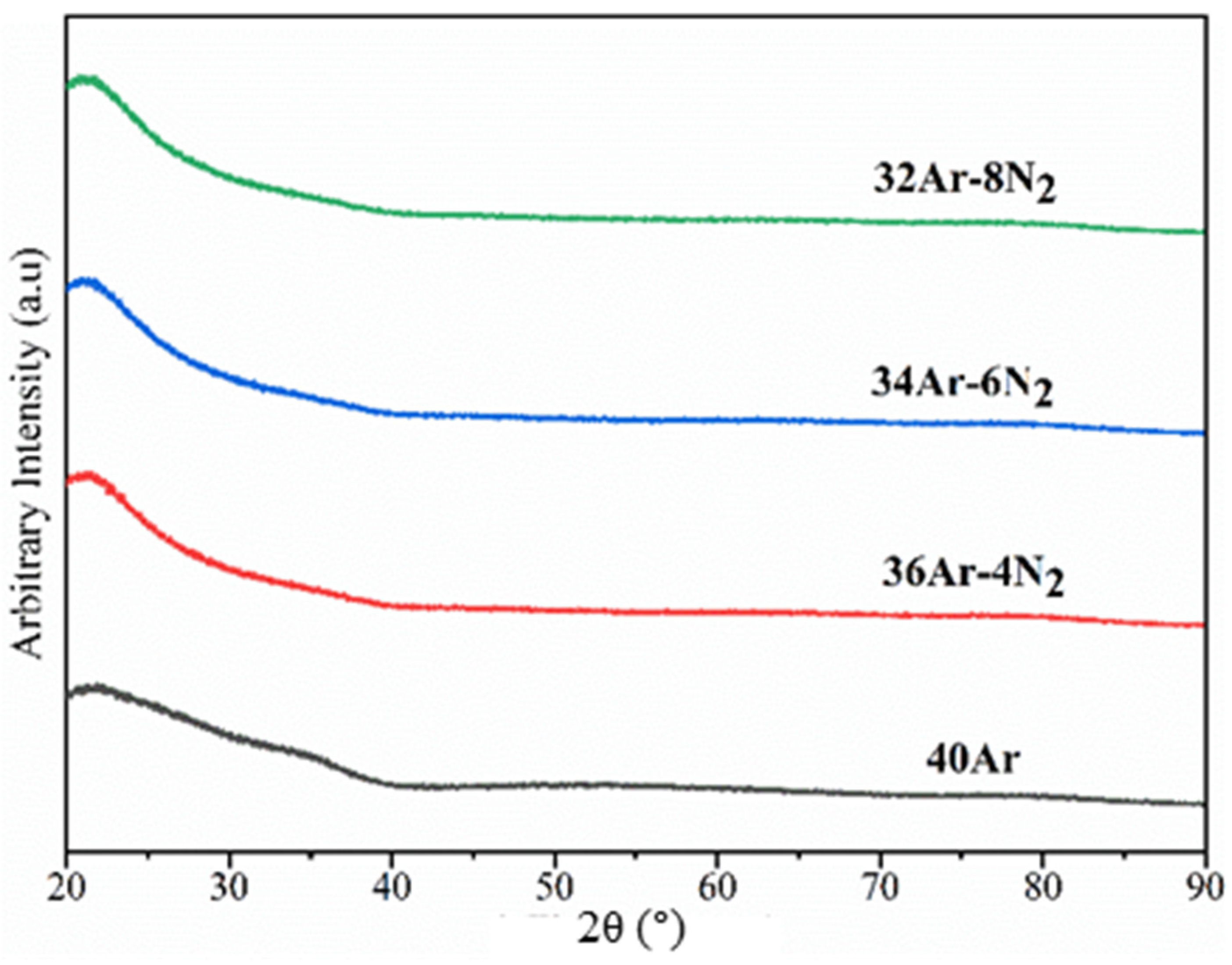
Figure 1. XRD spectra of Ta2O5 coatings deposited at a sputtering power of 140 W with different N2 and Ar fluxes.
Coatings 12 01745 g001
Figure 2. XPS spectra of 34 sccm Ar-6 sccm N2 and Ta2O5 coatings prepared at a sputtering power of 140 W (a): Ta4f (b), O1s (c), Ta-N and Ta4P3/2 (d).
Coatings 12 01745 g002
Figure 3. SEM images of surface and cross-section morphology of Ta2O5 coatings prepared at a sputtering power of 140 W under different N2 and Ar gas flow rates: (a) 40Ar, (b) 36Ar-4N2, (c) 34Ar-6N2, (d) 32Ar-8N2.
Coatings 12 01745 g003
Figure 4. AFM images of Ta2O5 coatings deposited at a sputtering power of 140 W under different N2 and Ar flow rates. (a) 40Ar, (b) 36Ar4-N2, (c) 34Ar-6N2, (d) 32Ar-8N2.
Coatings 12 01745 g004
Figure 5. EDS energy spectrum of Ta2O5 coatings prepared with different N2 flow rates and a sputtering power of 140 W. (a) 40Ar, (b) 36Ar-4N2, (c) 34Ar6-N2, (d) 32Ar-8N2.
Coatings 12 01745 g005
Figure 6. The transmittance of Ta2O5 coatings deposited at a sputtering power of 140 W under different N2 and Ar flow rates.
Coatings 12 01745 g006
Figure 7. Optical band gap of Ta2O5 coatings prepared at different N2 and Ar gas flow rates with a sputtering power of 140 W. (a,b) 40Ar, (c,d) 36Ar-4N2, (e,f) 34Ar-6N2, (g,h) 32Ar-8N2.
Coatings 12 01745 g007
Publisher’s Note: MDPI stays neutral with regard to jurisdictional claims in published maps and institutional affiliations.