Article

Synthesis Optimization of Cadmium Carbonate Films as Potential Precursor to Produce CdSe, CdTe, and CdO Films

by
J. A. Heredia-Cancino
1,*,
K. J. Mendoza-Peña
2,
H. J. Higuera-Valenzuela
3,
M. Anahí Soto B.
4,
R. Ochoa-Landín
5 and
S. J. Castillo
6
1
P.E. Ingeniería Mecatrónica, Universidad Estatal de Sonora, Av. Ley Federal del Trabajo s/n, Col. Apolo, Hermosillo 83100, Sonora, Mexico
2
Department of Materials and Synchrotron Radiation Engineering, Graduate School of Engineering, University of Hyogo, 2167 Shosha, Himeji 671-2280, Hyogo, Japan
3
P.E. Ingeniería Biomédica, Universidad Estatal de Sonora, Av. Ley Federal del Trabajo s/n, Col. Apolo, Hermosillo 83100, Sonora, Mexico
4
Coordinación de Investigación y Posgrado, Universidad Estatal de Sonora, Av. Ley Federal del Trabajo s/n, Col. Apolo, Hermosillo 83100, Sonora, Mexico
5
Departamento de Física, Universidad de Sonora, Blvr Luis Encinas s/n, Col Centro, Hermosillo 83000, Sonora, Mexico
6
Departamento de Investigación en Física, Universidad de Sonora, Blvr Luis Encinas s/n, Col Centro, Hermosillo 83000, Sonora, Mexico
*
Author to whom correspondence should be addressed.
Coatings 2022, 12(11), 1691; https://doi.org/10.3390/coatings12111691
Submission received: 11 October 2022 / Revised: 1 November 2022 / Accepted: 3 November 2022 / Published: 7 November 2022

Abstract

:
Cadmium-derived materials are highly demanded for optoelectronics applications, and the scientific community has widely worked in different ways to develop them. In this research, the optimization of CdCO3 films using a chemical bath deposition (CBD) method at different deposition times (10, 11, and 12 h) is reported. The intention to optimize CdCO3 films is in order to propose it as a precursor to produce different types of cadmium-derived semiconductors such as CdSe, CdTe, and CdO. The obtained films were characterized by X-ray diffraction (XRD), Raman spectroscopy, Fourier-transform infrared (FTIR) spectroscopy, optical absorption by diffuse reflectance, scanning electron microscopy (SEM), and energy-dispersive spectroscopy (EDS). The results provide evidence that CdCO3 films were effectively synthesized, featuring a rhombohedral crystalline structure with a preferential plane (104), and crystallite sizes were 65, 69, and 87 nm for the deposited samples at 10, 11, and 12 h, respectively. Surface morphology analysis revealed microstructures around 3–5 μ m , with a deltoid shape, agglomerated and distributed randomly for all samples. The bandgap obtained was 3.78 eV for all samples.

1. Introduction

The search for new methods for the deposition of thin films has become relevant since the last decade, particularly for those semiconductors that require expensive processes and special conditions. The use of precursor films as a source of a metal has allowed the synthesis of different semiconductors through ion exchange in an aqueous or gaseous state. Zhu et al. [1] synthesized a PbSe film using a plumbonacrite precursor film as a lead source, and then performed an ion exchange in aqueous conditions by immersing the precursor film in a Na2SeSO3 solution. They described the chemical reactions involved in the ion exchange between lead byproducts present in plumbonacrite (PbO, PbCO3, and Pb(OH)2) and Se−2 ions, resulting in a complete transformation to PbSe after an immersion time of 1.5 h. Fernández-Díaz et al. [2] used a silver precursor film (silver hydrogen oxide carbonate film) to synthesize an AgSe film by introducing it into a solution rich in Se−2 ions; selenium ions were prepared by reducing metallic selenium with rongalite, which acts as a reducing agent in an alkaline medium. The characterizations they carried out confirmed the development of AgSe films, which have potential application as an absorber layer in thin-film solar cells due to their direct banggap of 1.37 eV. Mattinen et al. [3] reported a new molybdenum precursor film, which, when immersed in H2S, is converted to MoS2. They highlighted the importance of synthesizing MoS2 films using this method, as they were able to control the thickness and scale of the MoS2 films; this is in contrast to other methods reported in the literature, since producing high-quality MoS2 films in large areas with controllable thicknesses for the different optoelectronic applications remains a big challenge. Chávez Urbiola et al. [4] transformed a lead precursor film into PbTe by introducing it into a tellurium atmosphere. They reported that the characteristics obtained using this mechanism are similar to those obtained using other direct methods of PbTe synthesis, when comparing the response of a PbTe-p/Si-n type photodiode using the PbTe synthesized according to a two-step and direct method. Gujar et al. [5] and Chávez Urbiola [6] reported Cd(OH)2 and Cd(O2)0.88(OH)0.24 films, respectively, which reacted to a thermal treatment with an oxygen atmosphere at temperatures between 200 and 500 °C to become CdO films, due to ion exchange between OH and O2− ions. In addition, they highlighted the need to obtain CdO films from different precursors, with the intention of finding the most efficient and effective method to produce CdO films with the properties required in their different applications despite its danger and toxicity, without the need for subsequent procedures. Sotelo-Lerma et al. [7] and Ochoa-Landín et al. [8] synthesized CdTe films by performing an ion exchange in aqueous medium with Te−2 ions on Cd(OH)2 and Cd(O2)0.88(OH)0.24, respectively. They were among the first to report in the literature the elaboration of CdTe films using chemical bath deposition (CBD) in two steps; the results confirmed the complete transformation to CdTe. The main difficulty of the process is the stability of Te−2 ions in solution for an effective ion exchange; however, the method is relatively simple and represents an economical alternative for the synthesis of CdTe. Furthermore, Chávez Urbiola et al. [9] synthesized CdSe films using cadmium precursor films exposed to gaseous ion exchange with Se−2 ions. The main advantage of producing CdSe films using this two-step method is the ability to produce thicker precursor films according to the CBD method (a thickness of 20 μm was reported), which is favorable for photovoltaic applications due to its potential use as an absorbent layer, which can hardly be produced using one-step physical processes. Moreover, it is important to mention that the synthesis of nanocrystals of cadmium derivatives has been reported using an ion tracking template, with properties different from those of films [10,11,12].
Our working group is focused on synthesizing precursor films that can carry out ion exchange in a liquid or gas phase, as an alternative to common methods while avoiding expensive reagents [2,7,8,9,13,14]. CdCO3 is a good candidate to be used as a cadmium precursor film, since it meets one of the main characteristics of a precursor film, which is to have an ion that can be relatively easy to remove, such as the CO3−2 ion that has been reported in reaction mechanisms in ion exchange [1,4], and that can be replaced by selenium, tellurium, and oxide ions to produce CdSe, CdTe, and CdO, respectively. In this study, the optimization of the synthesis of CdCO3 films deposited using CBD on Corning glass substrates at different times is reported. XRD, Raman, and FTIR spectroscopy characterizations were conducted to determine the structure of the material; in addition, SEM and EDS were performed to analyze the morphology of the surface and the chemical composition of the material, respectively.

2. Experimental

The films were synthesized using CBD, and all precursors were analytical grade. In a previous study [15], two formulations were reported to synthesize CdCO3 films, along with the reaction mechanism; the optimized method to produce CdCO3 films is now reported, which consists of doubling the volume of sodium citrate and reducing the temperature from 70 to 50 °C. The reaction solution consisted of sequentially adding the following in a 100 mL beaker: 5 mL of cadmium chloride 0.5 M, 20 mL of sodium citrate 1.0 M, 15 mL of ammonium hydroxide 2.0 M, 5 mL of sodium bicarbonate 1.0 M, and 55 mL of deionized water. Once all precursors were in the beaker, borosilicate glass substrates with dimensions of 25 mm × 75 mm × 1.1 mm were used; substrates were cleaned with commercial soap and deionized water, and then placed at opposite extremes close to the beaker walls, keeping them upright. The reaction temperature was set at 50 °C for 3 h; after 1 h, the substrates were rinsed with deionized water in order to stimulate a better nucleation process, before being returned to the beaker to finish 3 h at 50 °C. Finally, the reaction was allowed to continue for 7, 8, and 9 h in room conditions, after which the substrates were removed from the beaker, rinsed with deionized water, and left vertically to dry. The samples were labeled according to the sum of the reaction time in the bath and the complementary growth time under room conditions, i.e., 10, 11, and 12 h, respectively. In addition, the samples were immediately characterized to avoid changes in their properties.
The equipment used to characterize the obtained films were as follows: XRD analysis using PANalytical X-Ray diffractometer, model X’Pert MRD PRO; Raman spectrum using a XploRA RAMAN microscope HORIBA system (785 nm); FTIR spectroscopy in transmittance mode using a PerkinElmer UATR Spectrum Two equipment; diffuse reflectance using a Perkin Elmer UV/VIS/NIR Lambda 19 Spectrometer; surface morphology and chemical composition analysis using an FE-SEM JEOL JSM-7800F SEM and EDS.

3. Results and Discussion

3.1. XRD Analysis

The films obtained resulted thick, homogeneous, uniform, and with good adhesion to the Corning glass substrate. Figure 1 displays theXRD patterns of CdCO3 films deposited at 10, 11, and 12 h. At the bottom, the XRD pattern of the crystallography reference for CdCO3 in its mineral phase (otavite) is shown. The diffraction peaks of the reference match well with the XRD patterns of the films synthesized; according to the reference, it has a rhombohedral crystalline structure and a preference plane (104) at about 30°. The peak intensity at different times of deposition does not illustrate a significant change in the diffractograms; only peaks (012), (104), and (110) seemed to increase in intensity, and the formation of impurities was not observed. Furthermore, the crystallite size was calculated according to the Debye–Scherrer equation (Equation (1)).
D = 0.9 λ β c o s θ ,
where D is the crystallite size, β is the full width at half maximum (FWHM) in radians, λ is the wavelength of the X-ray source (CuKα = 1.5406 Å), and θ is the diffraction angle. The approximate crystallite size for the deposited films at 10, 11, and 12 h, were 65, 69, and 87 nm, respectively.

3.2. Raman Spectroscopy

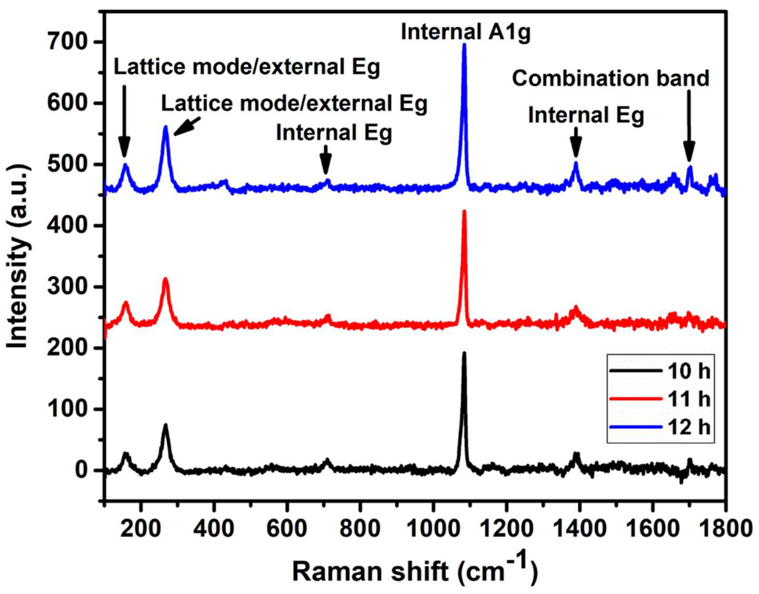
The Raman spectra are shown in Figure 2. According to [16,17,18], six Raman frequencies associated with the CO3−2 group exist. The signals around 1083 (ν1), 1397 (ν3), and 711 cm−14) correspond to symmetric stretching of C–O (A1g), asymmetric stretching of C–O (Eg), and in-plane bending for CO32−, respectively. Furthermore, the vibration frequencies at 158 (ν14) and 267 cm−113) are associated with the vibrational lattice modes of the CO32− group bonded with cadmium [19]. The signal observed at 1714 cm−1 is related to the combination of symmetric and asymmetric internal vibrations of C–O (A1g + Eg) [14,15,16].
On the other hand, as the deposition time increased, other vibrational modes did not appear, indicating that the growth process of the films was free from the formation of oxides or impurities.

3.3. FTIR Spectroscopy

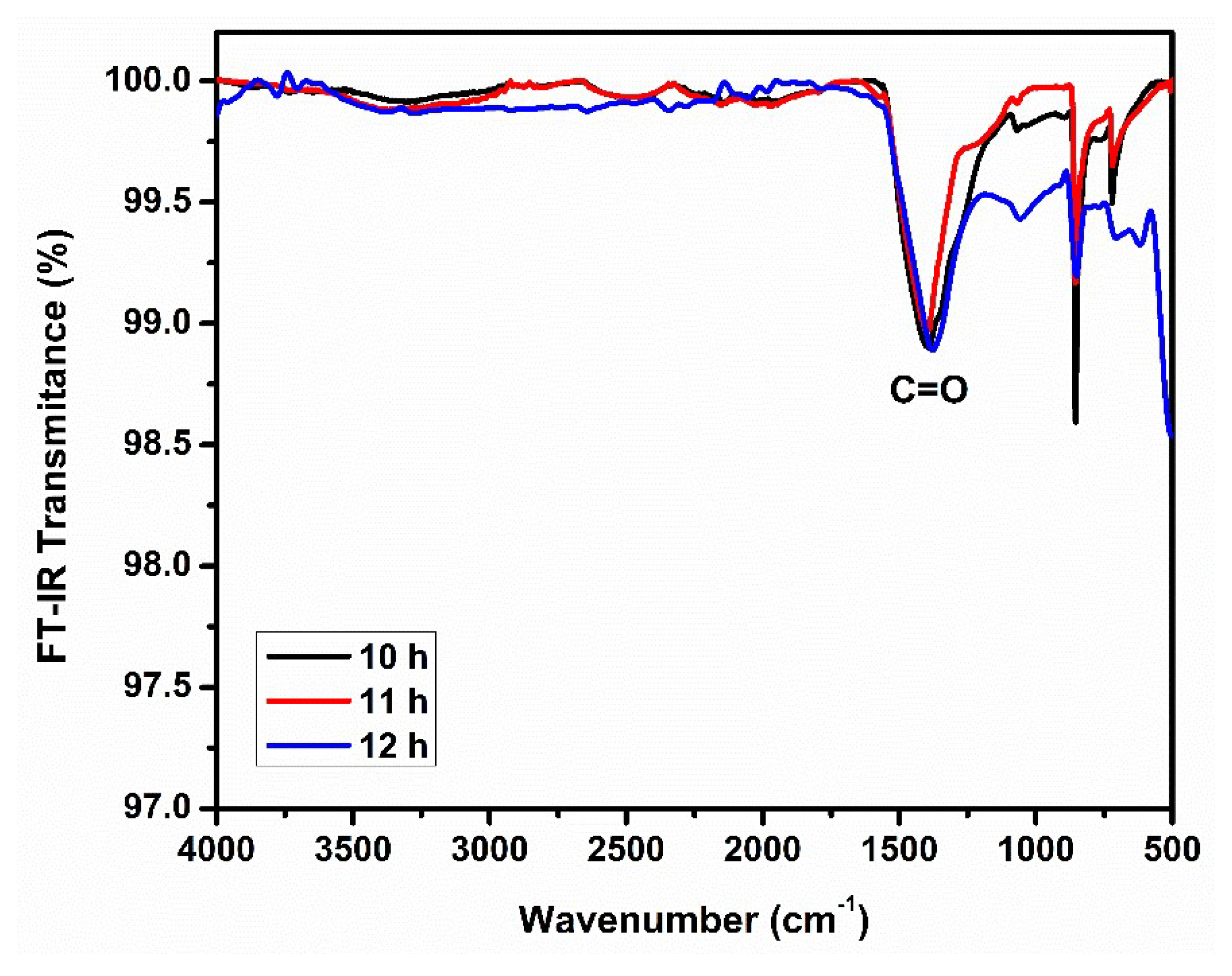
Figure 3 displays the FTIR transmission spectra; the absorption peaks observed at 705, 852, and 1373 cm−1 are associated with the CO32− vibrations [16,17,20,21]. Furthermore, the band at 1395 cm−1 is assigned to CO32−3), that at 853 cm−1 is assigned to CO3−22), and that at 705 cm−1 is assigned to CO3−22) [17]. The wavenumber ν3 corresponds to asymmetric stretching vibrations, whilst ν2 is associated with out-of-plane bending vibrations [16]. Therefore, the presence of CO32− in the deposited films can be confirmed, which is correlated with Raman characterization, strongly supporting the results. Moreover, the absorption bands between 700 and 500 cm−1 correspond to residual carbon compounds [22].

3.4. SEM and EDS

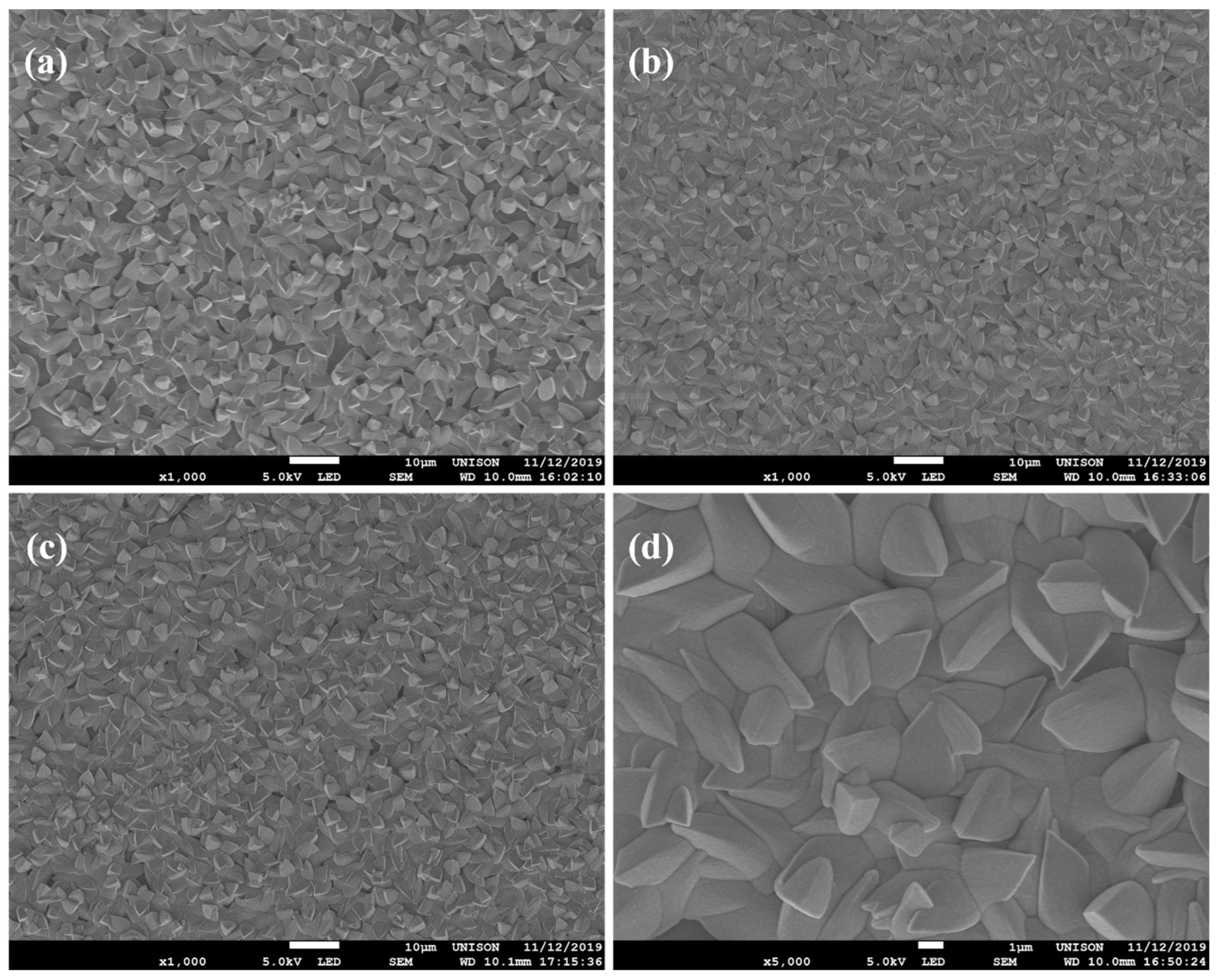
The morphologies of the samples are shown in Figure 4 and labeled as (a), (b), and (c), corresponding to films deposited at 10, 11, and 12 h, respectively. Figure 4d exhibits a close-up of the morphology of the sample at 11 h to observe its shape and size. It can be seen that the entire surface area of the substrate was covered; as the deposition time increased, the morphology became more uniform and denser. The size of the microstructures was around 3–5 µm, with a deltoid shape, agglomerated and distributed randomly for all samples. In a previous study [15], the morphology revealed agglomerated clusters with a butterfly cocoon shape. The difference in these morphologies is attributed to the optimized formulation and conditions to synthetize CdCO3 films since temperature was reduced from 70 to 50 °C and bath time incremented from 1 to 3 h. The effect of reducing the temperature in combination with the double molarity of sodium citrate produced a decrease in the deposition time, due to a higher proportion of cadmium ionic complexes, which led to a more controlled, uniform, denser, and rapid formation of the film on the substrate. However, in the literature, different morphologies are reported, depending on the conditions and methods of synthesis, yielding many forms [23,24].
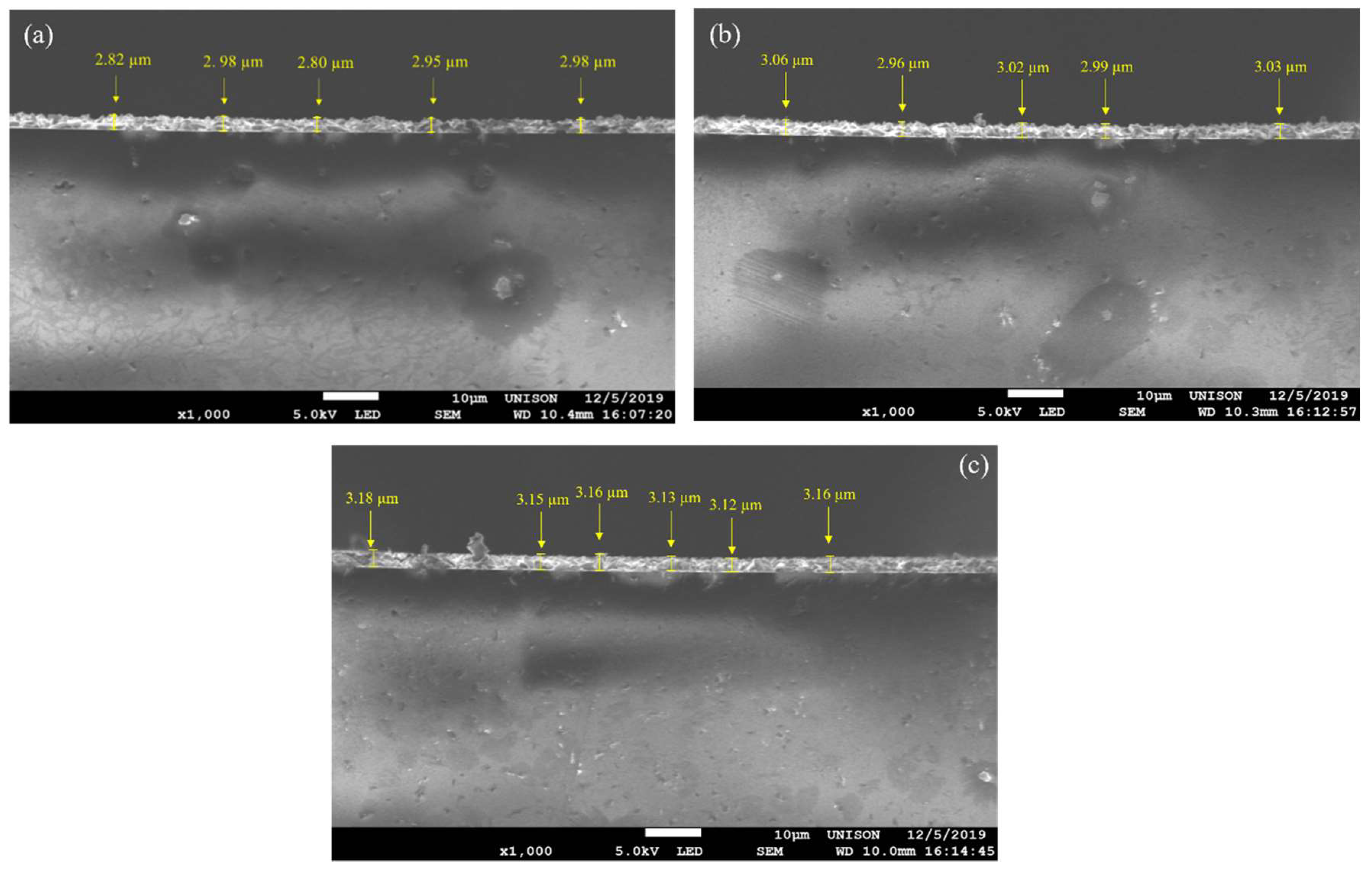
The thickness of films was measured using cross-sectional SEM. Figure 5 displays the cross-section micrography of the deposited samples at 10, 11, and 12 h, whose thicknesses were approximately 2.90, 3.00, and 3.15 µm. These thicknesses are promising because cadmium-derived semiconductor applications require a thick film, as they are used as an absorber layer in optoelectronic applications. Therefore, this method represents a good alternative to physical methods, since obtaining CdCO3 films with thicknesses greater than 1 µm is simple, economical, and scalable.
Figure 6 reveals the EDS analysis of the global area of the micrographs corresponding to the series of samples, showing a relationship of atomic percentages very close to the stoichiometric relationship in the formula of the compound CdCO3 [25]. Furthermore, there were no considerable impurities in the samples, with silicon coming from the substrate and sodium coming from the precursors, both with atomic percentages less than 1.31%. Therefore, the results of the EDS analysis exhibit the successful high-purity synthesis of CdCO3 using the CBD technique at different deposition times. This result supports the feasibility of using CdCO3 films as a precursor material to produce CdSe, CdTe, and CdO via ion exchange in an aqueous solution or sublimation.

3.5. Reflectance and Direct Bandgap

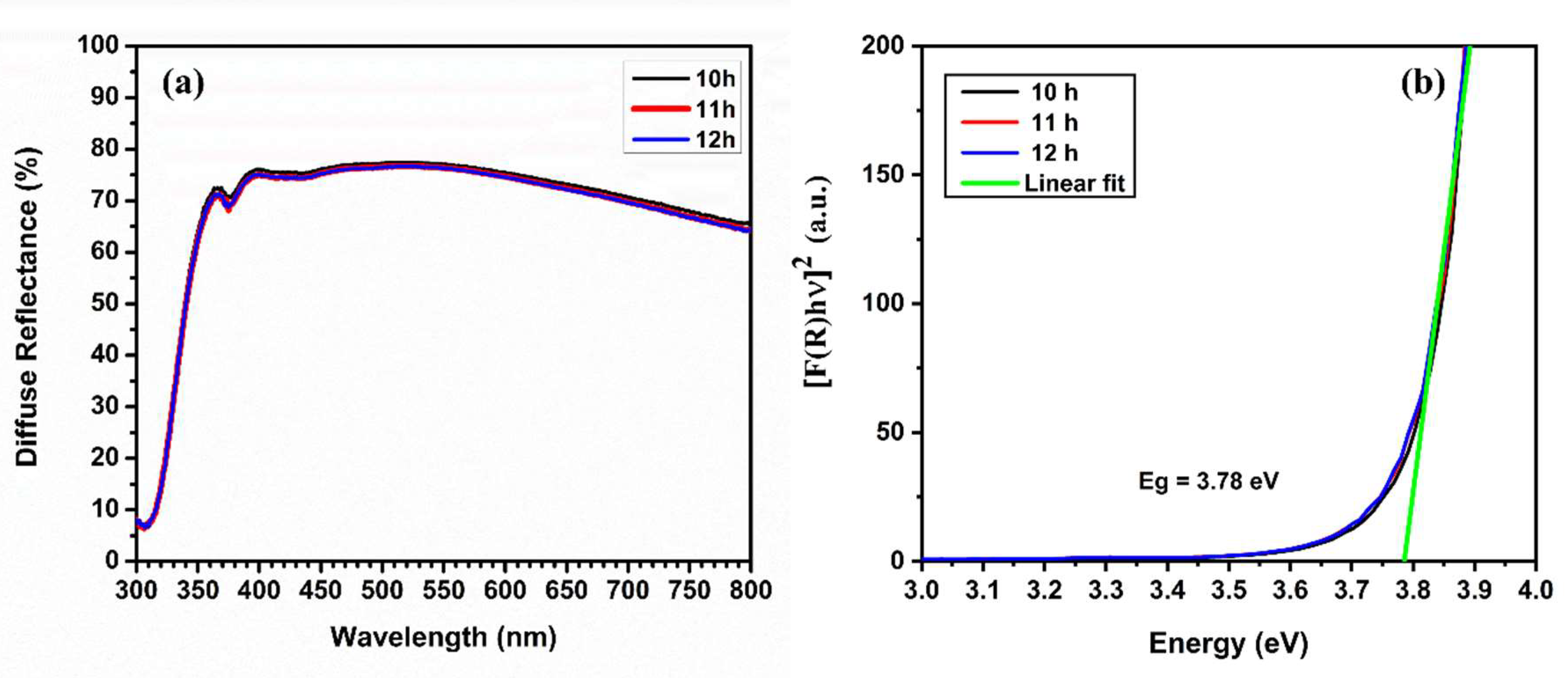
Diffuse reflectance results are displayed in Figure 7a, which were processed to obtain the bandgap values using the Kubelka Munk method (Figure 7b) (see [26,27]). The diffuse reflectance for the samples presented no remarkable variations; as can be observed, their reflectance was on the order of 70% in the 400–800 nm range for all samples, which is related to the thicknesses of the film. A noticeable edge began around wavelengths from 328 nm to 370 nm, associated with the absorption spectrum for CdCO3 films. The estimation of the energy bandgap was carried out according to the following procedure, considering that the Kubelka Munk function is proportional to the optical absorption of the material, with a computational improvement in the estimation of the intersection with hν axis [28]: [F(R)hν]2 was plotted against the photon energy hν, and then, to estimate the energy bandgap analytically, a linear fit was performed to obtain the best position of the tangent line correlated with the start of the absorption edge; therefore the portion of the straight line was extrapolated from the straight segment of the graph to the hν intercept, obtaining a bandgap estimate of 3.78 eV for all CdCO3 films, which is quite close to the values reported in the literature, hovering between 3.86 and 4.00 eV [15,24].
Portillo Moreno et al. [24] reported thin films of CdCO3 through a formulation used to deposit thin films of CdS based on thiourea as a source of S−2 ions, which, when reacting at temperatures between 40 and 60 °C, provides CO3−2 ions and produces CdCO3. They reported a low sulfur concentration in the CdCO3 films resulting from the use of thiourea, while 3–8 μm microstructures in the shape of cubes, circles, and cables of different sizes with agglomerations were observed in the SEM micrographs. Furthermore, the thickness reached in the film was 2.04 μm for a deposition time of 12 h, while, in this study, a thickness of 2.9 μm was reached in 10 h by another formulation; they finally reported a band gap of 4.0 eV. A later study was reported by Moreno Morales et al. [29], with CdCO3 films converted to CdO by applying a heat treatment in an air atmosphere at 400 °C for 1 h. Similarly, CdCO3 was deposited using CBD at room temperature instead of 40 °C in the original formulation. The analysis of the chemical composition of the CdCO3 films after heat treatment revealed a good stoichiometry of Cd/O ≈ 1; however, they mentioned that it was necessary to apply more heat treatment time to convert all the CdCO3 to CdO, since some CO32− residues were detected in FTIR analysis. In addition, an increase in the transmission spectrum and the expected bandgap for CdO was noticeably observed. They also mentioned a lack of studies and models on the decomposition and possible ion exchange processes of CdCO3, particularly in films. One of the main advantages of CdCO3 films over films of Cd(OH)2 and Cd(O2)0.88(OH)0.24, as reported by Gujar et al. [5], Sotelo-Lerma [7], Chávez Urbiola [6], and Ochoa-Landín [8], is the deposition process, since it does not require H2O2, which simplifies and avoids destabilization of the pH of the reaction. In addition, the Cd(OH)2 film, when subjected to ion exchange in aqueous conditions, is very prone to detach from the substrate due to a lack of adhesion, requiring special treatment, while the CdCO3 films are more uniform and dense, along with a better adhesion to the substrate. Table 1 presents a comparison of the bandgap energies for the cadmium precursor films mentioned above.

4. Conclusions

The CBD deposition method of cadmium carbonate films was optimized, reducing its deposition time from 12 to 10 h. The synthesized films presented a thickness between 2.90 and 3.15 μm, uniformity, homogeneity, and good adhesion to the substrate. XRD analysis showed CdCO3 in its mineral phase (otavite) with a rhombohedral crystal structure with a preferential plane (104) at approximately 30°; crystallite sizes were 65, 69, and 87 nm for 10, 11, and 12 h, respectively. FTIR analysis showed absorption peaks associated with CO32− vibrations, supporting the results of Raman spectroscopy. The estimated bandgap was approximately 3.78 eV for all films. The SEM micrographs showed the morphology of the surface with agglomerations of deltoid-like microstructures with a size of 3–5 μm, unlike the butterfly cocoon-like microstructures reported in a previous study, whose size was around 5–10 μm. We attribute this change in microstructure to the optimization process, which involved changing the reaction temperature from 70 to 50 °C and the reaction time from 1 to 3 h. The EDS analysis found a stoichiometric relationship very close to the formula of the CdCO3 compound, evidencing a successful process in optimizing the synthesis of CdCO3 films and postulating them as excellent candidates to be cadmium precursor films to synthesize CdSe, CdTe, and CdO using ion exchange processes.

5. Patents

This research is in the patent process in Mexico under the ID MX/a/2017/014496.

Author Contributions

Conceptualization, J.A.H.-C., K.J.M.-P., R.O.-L. and S.J.C.; investigation, J.A.H.-C., K.J.M.-P., H.J.H.-V. and M.A.S.B.; methodology, J.A.H.-C., K.J.M.-P., H.J.H.-V. and M.A.S.B.; resources, R.O.-L. and S.J.C.; supervision, R.O.-L. and S.J.C.; writing—original draft, K.J.M.-P., H.J.H.-V. and M.A.S.B.; writing—review and editing, J.A.H.-C., R.O.-L. and S.J.C. All authors read and agreed to the published version of the manuscript.

Funding

This research was partially supported by Universidad Estatal de Sonora, project UES-PII-20-UAH-IIM-01.

Institutional Review Board Statement

Not applicable.

Informed Consent Statement

Not applicable.

Data Availability Statement

Data are available on request due to privacy/ethical restrictions. The data presented in this study are available on request from the corresponding authors. The data are not publicly available due to their ability to potentially compromise the privacy of research participants.

Acknowledgments

We thank Amanda Carrillo-Castillo from UACJ for the XRD measurements.

Conflicts of Interest

The authors declare no conflict of interest.

References

  1. Zhu, Y.; Hou, H.; Liu, G.; Zhang, X.; Lv, Q.; Yang, J.; Liu, J.; Qiao, G. Microstructures and optical properties of porous PbSe film prepared by ion exchange process. Mater. Sci. Semicond. Process. 2022, 147, 106741. [Google Scholar] [CrossRef]
  2. Fernández-Díaz, E.; Espinoza-Martinez, A.B.; Flores-Pacheco, A.; Ramírez-Bon, R.; Castillo, S.J.; Ochoa-Landin, R. Synthesis and Characterization of Silver Selenide Thin Films by Chemical Bath Deposition and Ionic Exchange. J. Electron. Mater. 2019, 48, 3405–3409. [Google Scholar] [CrossRef]
  3. Mattinen, M.; Hatanpää, T.; Sarnet, T.; Mizohata, K.; Meinander, K.; King, P.J.; Khriachtchev, L.; Räisänen, J.; Ritala, M.; Leskelä, M. Atomic Layer Deposition of Crystalline MoS2 Thin Films: New Molybdenum Precursor for Low-Temperature Film Growth. Adv. Mater. Interfaces 2017, 4, 1700123. [Google Scholar] [CrossRef] [Green Version]
  4. Urbiola, I.R.C.; Bon, R.R.; Vorobiev, Y.V. Lead Telluride Through Transformation of Plumbonacrite in Tellurium Atmosphere and Its Behavior as Part of PbTe–Si Photodiode. IEEE Sens. J. 2016, 16, 5875–5882. [Google Scholar] [CrossRef]
  5. Gujar, T.; Shinde, V.; Kim, W.-Y.; Jung, K.-D.; Lokhande, C.; Joo, O.-S. Formation of CdO films from chemically deposited Cd (OH) 2 films as a precursor. Appl. Surf. Sci. 2008, 254, 3813–3818. [Google Scholar] [CrossRef]
  6. Chávez Urbiola, I.R.; Ramírez Bon, R.; Vorobiev, Y.V. The transformation to cadmium oxide through annealing of cadmium oxide hydroxide deposited by ammonia-free SILAR method and the photocatalytic properties. Thin Solid Film. 2015, 592, 110–117. [Google Scholar] [CrossRef]
  7. Sotelo-Lerma, M.; Zingaro, R.A.; Castillo, S.J. Preparation of CdTe coatings using the chemical deposition method. J. Organomet. Chem. 2001, 623, 81–86. [Google Scholar] [CrossRef]
  8. Ochoa-Landín, R.; Castillo, S.J.; Ramírez-Bon, R. Growth from solution of CdTe films by conversion of chemically deposited cadmium oxide hydroxide films. Solar Energy 2012, 86, 3326–3330. [Google Scholar] [CrossRef]
  9. Chávez-Urbiola, I.R.; Chávez-Urbiola, E.A.; Ochoa-Landín, R.; Castillo, S.J.; Vorobiev, Y.V.; Ramírez-Bon, R. Cadmium selenide film through ammonia free thermal substitution reaction on cadmium oxide hydroxide films by chemical vapor deposition. Mater. Lett. 2014, 116, 254–257. [Google Scholar] [CrossRef]
  10. Balakhayeva, R.; Akilbekov, A.; Baimukhanov, Z.; Usseinov, A.; Giniyatova, S.; Zdorovets, M.; Vlasukova, L.; Popov, A.I.; Dauletbekova, A. CdTe Nanocrystal Synthesis in SiO2/Si Ion-Track Template: The Study of Electronic and Structural Properties. Phys. Status Solidi 2021, 218, 2000231. [Google Scholar] [CrossRef]
  11. Akilbekov, A.; Balakhayeva, R.; Zdorovets, M.; Baymukhanov, Z.; Komarov, F.F.; Karim, K.; Popov, A.I.; Dauletbekova, A. Ion track template technology for fabrication of CdTe and CdO nanocrystals. Nucl. Instrum. Methods Phys. Res. Sect. B Beam Interact. Mater. At. 2020, 481, 30–34. [Google Scholar] [CrossRef]
  12. Karbovnyk, I.; Bolesta, I.; Rovetskyi, I.; Lesivtsiv, V.; Shmygelsky, Y.; Velgosh, S.; Popov, A.I. Long-term evolution of luminescent properties in CdI2 crystals. Low Temp. Phys. 2016, 42, 594–596. [Google Scholar] [CrossRef] [Green Version]
  13. Heredia-Cancino, J.A.; Mendivil-Reynoso, T.; Ochoa-Landin, R.; Ramírez-Bon, R.; Castillo, S.J. Optical and structural properties of PbSe films obtained by ionic exchange of lead oxyhydroxicarbonate in a selenium-rongalite solution. Mater. Sci. Semicond. Process. 2016, 56, 90–93. [Google Scholar] [CrossRef]
  14. Heredia-Cancino, J.A.; Salcido, O.; Britto-Hurtado, R.; Ruvalcaba-Manzo, S.G.; Ochoa-Landín, R.; Castillo, S.J. CdS/PbSe Heterojunction Made via Chemical Bath Deposition and Ionic Exchange Processes to Develop Low-Cost and Scalable Devices. Appl. Sci. 2021, 11, 914. [Google Scholar] [CrossRef]
  15. Ruvalcaba-Manzo, S.G.; Castillo, S.J.; Ochoa-Landín, R.; Flores-Acosta, M.; Ramírez-Bon, R. Optical, structural, and morphological characterization of cadmium carbonate thin films by CBD two formulations. Opt. Mater. 2020, 109, 110295. [Google Scholar] [CrossRef]
  16. Song, L.; Zhang, S.; Wu, X.; Wang, Z.; Wei, Q. Self-assemble, growth mechanism, and optical properties of complex and oriented 3D CdCO3 pyramids consist of single crystal parallel tetrahedrons. Chem. Eng. J. 2012, 195–196, 15–21. [Google Scholar] [CrossRef]
  17. Bucca, M.; Dietzel, M.; Tang, J.; Leis, A.; Köhler, S.J. Nucleation and crystallization of otavite, witherite, calcite, strontianite, hydrozincite, and hydrocerussite by CO2 membrane diffusion technique. Chem. Geol. 2009, 266, 143–156. [Google Scholar] [CrossRef]
  18. Rutt, H.N.; Nicola, J.H. Raman spectra of carbonates of calcite structure. J. Phys. C Solid State Phys. 1974, 7, 4522. [Google Scholar] [CrossRef]
  19. Minch, R.; Seoung, D.-H.; Ehm, L.; Winkler, B.; Knorr, K.; Peters, L.; Borkowski, L.; Parise, J.; Lee, Y.; Dubrovinsky, L.; et al. High-pressure behavior of otavite (CdCO3). J. Alloys Compd. 2010, 508, 251–257. [Google Scholar] [CrossRef]
  20. Chávez Portillo, M.; Chaltel Lima, L.A.; Peña Rosas, U.; Hernández Téllez, G.; Gutiérrez Pérez, R.; Portillo Moreno, O. Shape- and size controlled synthesis of CdCO3 in situ-doped-Er3+. Mater. Lett. 2014, 120, 130–132. [Google Scholar] [CrossRef]
  21. Chávez Portillo, M.; Sosa Sánchez, A.; Juárez Díaz, G.; Chaltel Lima, L.A.; Cruz Cruz, S.; Gutierrez Pérez, R.; Hernández Téllez, G.; Portillo Moreno, O. Optical, structural and morphological properties of CdS-CdCO3 films. Rev. Mex. Fis. 2015, 61, 83–87. [Google Scholar]
  22. Nevins, N.; Allinger, N.L. Molecular mechanics (MM4) vibrational frequency calculations for alkenes and conjugated hydrocarbons. J. Comput. Chem. 1996, 17, 730–746. [Google Scholar] [CrossRef]
  23. Ashoka, S.; Nagaraju, G.; Thipperudraiah, K.V.; Chandrappa, G.T. Controlled synthesis of cadmium carbonate nanowires, nanoribbons, nanorings and sphere like architectures via hydrothermal method. Mater. Res. Bull. 2010, 45, 1736–1740. [Google Scholar] [CrossRef]
  24. Moreno, O.P.; Pérez, R.G.; Portillo, M.C.; García, M.E.A.; Moreno, G.E.; Cruz, S.C.; Rosas, E.R.; Lascano, M.H. Morphological, optical and structural analysis in CdS, CdS-CdCO3 and CdCO3 thin solid films grown by chemical bath. Optik 2018, 157, 388–399. [Google Scholar] [CrossRef]
  25. Anthony, J.W. Handbook of Mineralogy; Mineral Data Pub.: Tucson, AZ, USA, 1990. [Google Scholar]
  26. Abdullahi, S.S.; Güner, S.; Musa, Y.; Adamu, B.I.; Abdulhamid, M.I. Sımple method for the determınatıon of band gap of a nanopowdered sample usıng Kubelka Munk theory. NAMP J. 2016, 35, 241–246. [Google Scholar]
  27. Alcaraz de la Osa, R.; Iparragirre, I.; Ortiz, D.; Saiz, J.M. The extended Kubelka–Munk theory and its application to spectroscopy. ChemTexts 2020, 6, 2. [Google Scholar] [CrossRef]
  28. Brik, M.; Srivastava, A.; Popov, A.I. A few common misconceptions in the interpretation of experimental spectroscopic data. Opt. Mater. 2022, 127, 112276. [Google Scholar] [CrossRef]
  29. Moreno Morales, G.E.; Araiza Garcia, M.E.; Cruz Cruz, S.; Rebollo Plata, B.; Portillo Moreno, O.; Gutiérrez Pérez, R. CdCO3 nanocrystalline thin film grown by chemical bath and its transition to porous CdO by thermal annealing treatment. Optik 2018, 171, 347–355. [Google Scholar] [CrossRef]
  30. Sahin, B.; Bayansal, F.; Çakmak, H.M.; Kahraman, S.; Çetinkara, H.A. Effect of heat treatment on the properties of Cd(OH)2 and CdO films grown by chemical bath deposition. Philos. Mag. Lett. 2013, 93, 101–108. [Google Scholar] [CrossRef]
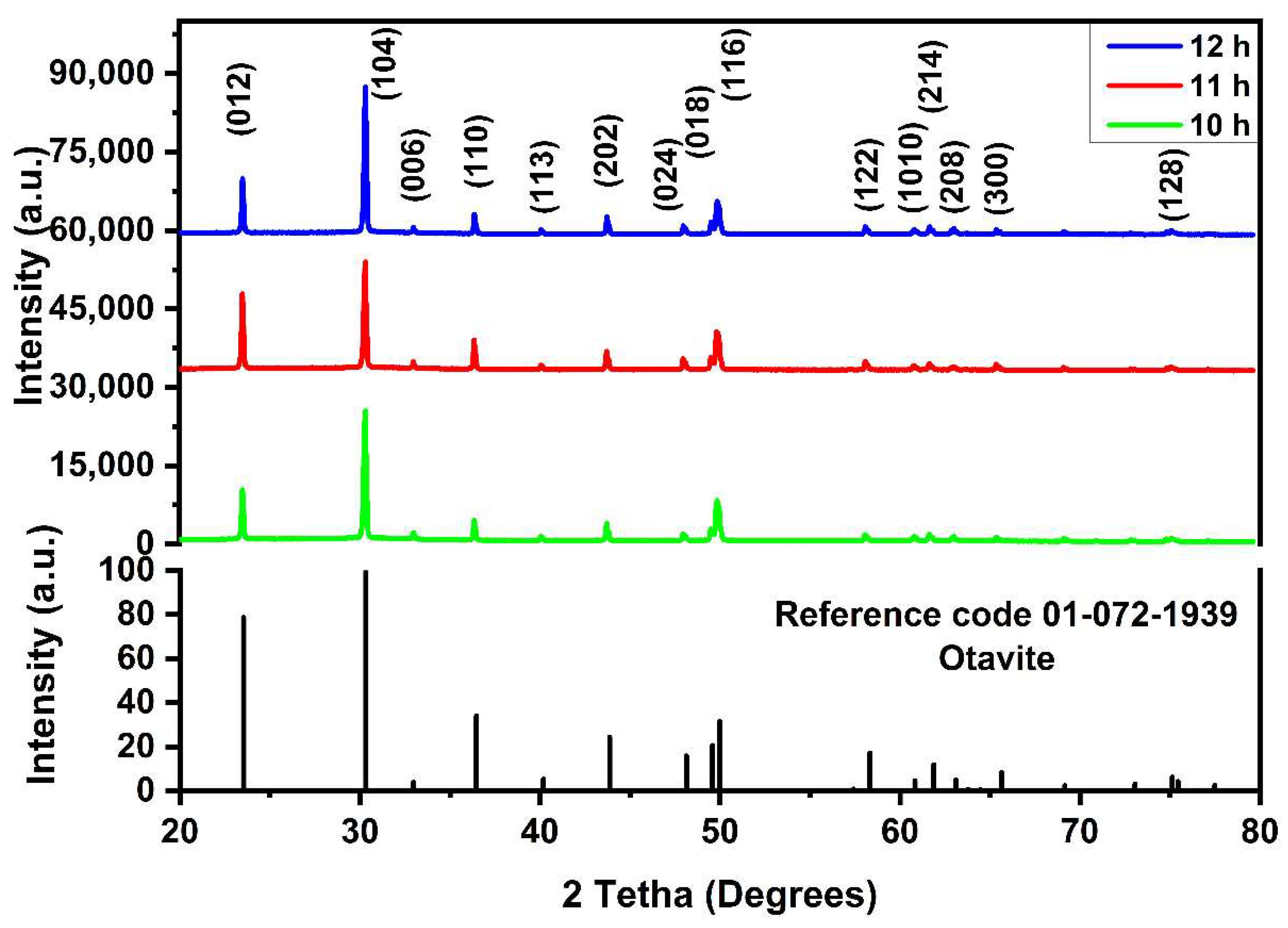
Figure 1. XRD diffractograms of the CdCO3 samples deposited at 10, 11, and 12 h.
Coatings 12 01691 g001
Figure 2. Raman spectra of the CdCO3 samples deposited at 10, 11 and 12 h.
Coatings 12 01691 g002
Figure 3. FTIR transmission spectra of the CdCO3 samples deposited at 10, 11, and 12 h.
Coatings 12 01691 g003
Figure 4. SEM micrographs of the CdCO3 samples deposited at (a) 10, (b) 11, and (c) 12 h; (d) micrograph of the deposited sample at 11 h with higher magnification.
Coatings 12 01691 g004
Figure 5. SEM micrographs showing the cross-section of the samples deposited at (a) 10, (b) 11, and (c) 12 h.
Coatings 12 01691 g005
Figure 6. EDS spectra of the samples at deposited (a) 10, (b) 11, and (c) 12 h.
Coatings 12 01691 g006
Figure 7. (a) Diffuse reflectance spectra and (b) direct bandgap of the CdCO3 films deposited at 10, 11, and 12 h.
Coatings 12 01691 g007
Table 1. Bandgap energies of different cadmium compounds used as precursor films.
Cadmium CompoundsBandgap (eV)
Cd(O2)0.88(OH)0.243.39 [6]
Cd(OH)22.74 [30]
CdCO33.78
Publisher’s Note: MDPI stays neutral with regard to jurisdictional claims in published maps and institutional affiliations.