Article

Liquid Nanofilms’ Evaporation Inside a Heat Exchanger by Mixed Convection

by
Abdelaziz Nasr
1,2,* and
Abdullah A. Alzahrani
1
1
Mechanical Engineering Department, College of Engineering and Islamic Architecture, Umm Al-Qura University, B. Po715, Makkah 21955, Saudi Arabia
2
Laboratory of Thermal and Energy Systems Studies, Monastir University, Ibn Eljazzar Street, Monastir 5019, Tunisia
*
Author to whom correspondence should be addressed.
Coatings 2022, 12(10), 1564; https://doi.org/10.3390/coatings12101564
Submission received: 1 September 2022 / Revised: 26 September 2022 / Accepted: 10 October 2022 / Published: 17 October 2022

Abstract

:
The present work focuses on a numerical investigation of nanofilms’ (water/copper and water/aluminium) evaporation inside a heat exchanger by mixed convection flowing down on one channel plate. The channel was composed of two parallel vertical plates. The wetted plate was heated while the other plate was maintained isothermal and dry. The impact of the dispersion of different types of nanoparticles in the liquid film and their volume fraction in mass and heat exchange and the evaporation process has been analysed in this work. The results show that an increase of the nanoparticle inlet volume fraction enhances the efficiency of evaporation in heat exchangers. It is shown that an enhancement of 22% in evaporation rate has been recorded when the inlet nanoparticle volume fraction is elevated by 5%. The results show that the water–copper nanofluid had higher evaporation rate compared to water–aluminium nanofluid.

1. Introduction

Nanofilm’s evaporation provides high thermal transfer rates because of its small thickness. This phenomenon is seen in heat pumps, heat exchangers, drying technology and nanotechnology applications. Do and Jang [1] showed that the heat transfer during liquid film evaporation is enhanced by the dispersion of nanoparticles into film. Zhao et al. [2] illustrated the impact of the dispersion of nanoparticles into a liquid film on its evaporation. They showed that the enhancement of the heat transfer during film evaporation is mainly due to the thermal conductivity enhancement of the liquid film. Numerical analyses of steady heat transfer and the forced turbulent flow of different nanofluids flowing inside a circular tube were presented by Namburu et al. [3]. The authors showed that an increase in the volume concentration of nanofluids induces pressure loss. Sefiane and Bennacer [4] experimentally analysed the effect of nanoparticle concentration on nanofluid viscosity. They showed that the dispersion of nanoparticles caused an increase in the nanofluid viscosity and then deterred drop evaporation. Gorjaei et al. [5] presented an analysis of the effect of adding Al2O3 nanoparticles in the heat transfer inside a three-dimensional annulus. A study of convective heat transfer of water containing CuO nanoparticles has been presented by Lazarus et al. [6]. They showed that the convective heat transfer coefficient of the nanofluid can be enhanced for a lower volume concentration of CuO nanoparticles. Chen et al. [7] presented the effects of nanoparticles on nanofluid droplet evaporation. They showed an enhancement of nanofluid evaporation in the case of packing of nanoparticles in the fluid. They showed that these nanoparticles (Laponite, Fe(2)O(3) and Ag-water) droplets evaporate at different rates from the base fluid (water). Siddiqa et al. [8] investigated of heat transfer by natural convection of nanofluid flow along a vertical surface by natural convection. It was shown that the dispersion of the nanoparticles ameliorates heat exchange. Sheremet et al. [9] numerically studied the free fluid flow of the convective heat transfer inside a porous wavy cavity in the presence of a nanofluid. They showed that the local heat source influenced the nanofluid flow and heat transfer rate. The effects of Brownian motion of nanoparticles and thermophoresis on the heat transfer during liquid film boiling have been analysed by Malvandi et al. [10]. Orejon et al. [11] presented a study of evaporation of water droplets containing titanium dioxide nanoparticles (TiO2) under direct current conditions. They showed that the TiO2 nanofluids’ receding contact was continuous and smooth when they applied direct current. Orejon et al. [12] treated the evaporation of water droplets containing different quantities of titanium oxide nanoparticles. Askounis et al. [13] studied the evaporation of water droplets containing a low concentration of Al2O3 nanoparticles. They concluded that the dispersion of Al2O3 nanoparticles in the water droplets at low concentrations did not affect the evaporation kinetics of droplets. Perrin et al. [14] analysed the evaporation of liquid drops containing a low nanoparticle concentration. A comparison between experimental and theoretical results of the evaporation of nanofluid liquid drops has also been presented. Abu-Hamdeh et al. [15] presented heat transfer and entropy formation of steady Prandtl–Eyring nanofluids. A numerical study of the first-grade viscoelastic nanofluid boundary layer flow with the transmission of entropy and heat was performed by Mashhour et al. [16]. Kam et al. [17] presented the removal of Tl(I) onto synthesised γ-alumina nanoparticles (γANPs) with a crystallite size of 4.1 nm. Yan [18] presented a numerical analysis of falling liquid film evaporation by mixed convection. Huang et al. [19] experimentally analysed liquid film evaporation. They showed that the increase of the inlet air flow rate and the inlet temperature enhanced the evaporation rate.
As regards the prior research, the numerical analysis of evaporation of water film containing a low-volume fraction of copper nanoparticle flowing down a vertical channel by mixed convection has not been considered. The main purpose of the present paper was to analyse the effect of the dispersion of copper nanoparticles in water liquid film on mass and heat exchange and on the efficiency of heat exchangers.

2. Numerical Model

The present work is focused on a numerical study of the evaporation of a water film flowing on one of two vertical plates under mixed convection (Figure 1). The water film contained copper nanoparticles. One plate was heated and wetted while the other plate was isothermal and dry. The nanofluid film entered the plate with a mass flow rate m0L, a temperature T0L and an inlet volume fraction of nanoparticle φ0. The ambient parameters at the inlet channel were the mass fraction of water vapour c0, the velocity u0, the temperature T0 and the pressure p0.

2.1. Assumptions

The simplifying hypothesis adopted for this study is:
  • The gas is perfect;
  • The nanoparticles and the liquid are in thermal equilibrium;
  • Transfers and flows are two-dimensional, laminar and steady.

2.2. Basic Equations

The governing equations of the nanofluid film evaporation in the two phases [2,10,18,20] are:

2.2.1. For the Liquid Film

Continuity
ρ n f u n f x L + ρ n f v n f y L = 0
x-Momentum
ρ n f u n f u n f x L + v n f u n f y L = ρ n f g d p n f d x L + y L μ n f u n f y L
Energy
ρ n f c p n f u n f T n f x L + v n f T n f y L = y L λ n f T n f y L + ρ p c p p y L D B φ y L T n f y L + D T T n f T n f y L 2
Nanoparticle concentration
u n f ϕ x L + v n f ϕ y L = y L D B ϕ y L + D T T n f T n f y L
where D B = β μ L ρ L φ , D T = k b T 3 π μ L d p and β = 0 . 26 λ L 2 λ L + λ p

2.2.2. For the Gaseous Phase

Continuity
ρ v y + ρ u x = 0
x-momentum
u u x + v u y = 1 ρ   d P d x β g ( T T 0 ) β * g ( c c 0 )   + 1 ρ y μ u y
Energy
u T x + v T y = 1 ρ c p y λ T y + ρ D ( c p v - c p a ) T y c y    
Specie concentration
v c y + u c x = 1 ρ y ρ D c y
Overall mass balance
δ d ρ u d y = ( d δ ) ρ 0 u 0 0 x ρ v ( x , 0 ) d x

2.3. Boundary Conditions

At x = 0
u = u0; T (0, y) = T0; P = P0 and c(0, y) = c0
T L ( 0 , y L ) = T 0 L ; m ( 0 ,     y L ) = m 0 L ;   φ = φ 0
At y = d:
v ( x = d , y ) = 0 ;   u ( x = d , y ) = 0 ; c i y y = d = 0 ; T ( x = d , y ) = T w
At yL = 0:
u n f ( x , 0 ) = v n f ( x , 0 ) = 0 ;   q 1 = λ nf T nf y L y L = 0
At yL = δ and y = 0:
The continuities of temperatures and velocities are:
u n f x , y L = δ = u x , y = 0 ;   T nf ( x ,   y L = 0 ) = T   ( x ,   y = 0 )
The continuities of shear stress give:
μ nf u nf y L y L = δ = μ u y y = 0
The energy equation at the interface is:
λ n f   T n f y L y L = δ = λ   T y y = 0 ρ   L v D 1 c ( x ,   0 ) c y y = 0

2.4. The Dimensionless Governing Equations

We introduce the following transformations:
In the gas:
η = (y − δ)(d − δ), ξ = x/H
In the liquid:
η L = y/δ, ξ = x/H

2.4.1. For the Liquid Phase

Continuity
ρ L u L ξ η L δ δ ξ ρ L u L η L + H δ ρ L v L η L = 0
x-momentum
u n f u n f ξ + ( v n f H δ u n f η L δ δ ξ ) u n f η L = 1 ρ L d P d ξ H ρ L δ 2 η L μ L u n f η L + g H
Energy
u n f T n f ξ + ( u n f η L 1 δ δ ξ + H δ v n f ) T n f η = 1 ρ n f C n f H δ 2 η L ( λ n f T n f η L )                                                                                     + ρ p C p p D B H ( δ ) 3 T n f η L φ η L + ρ p C p p D T T n f H ( δ ) 3 T n f η L 2
Nanoparticle concentration
u n f φ ξ + ( u n f η L 1 δ δ ξ + H δ v n f ) φ η = 1 ρ n f H δ 2 ( η L ( ρ n f D B φ η L )                                                                                                                                                                                     + η L ( ρ n f D T T n f T n f η L ) )

2.4.2. For the Gaseous Phase

Continuity
ρ u ξ + η 1 d δ δ ξ ρ u η + H d δ ρ v η = 0
x-momentum
u u ξ + ( η 1 d δ δ ξ u + H d δ v ) u η = 1 ρ d P d ξ g β H ( T T 0 ) g β H ( c c 0 )                                                                                                                                                                           + 1 ρ H d δ 2 η ( μ u η )
Energy
u   T ξ + ( u η 1 d δ   δ ξ + H d δ v )   T η = 1 ρ C p H d δ 2 η ( λ   T η )   + ρ D c p v c p a H ( d δ ) 2   T η   c η
Species diffusion
u c ξ + ( u η 1 d δ δ ξ + H d δ v ) c η = 1 ρ H d δ 2 η ( ρ D c η )
Overall mass balance
0 1 ρ ( d δ ) u ( ξ   ,   η ) d η = = ( d δ 0 ) ρ 0 u 0 H 0 ξ ρ v ( ξ   , η = 0 ) d ξ

2.4.3. Boundary Conditions

At ξ = 0 :
T (0, η) = T0; c(0, η) = c0; u(0, η) = u0; p(0, η) = p0
T L ( 0 ,   η L ) = T 0 L   ;   0 1 ρ 0 L δ 0 u L ( 0 , η L ) d η L = m 0 L   ;   φ = φ 0
At η = 1:
u ( ξ , 1 ) = v ( ξ , 1 ) = 0 ; c η η = 1 = 0 ; T ( ξ , 1 ) = T w
At ηL = 0:
u n f ( ξ , 0 ) = v n f ( ξ , 0 ) = 0 ; q w = λ L 1 δ T L η L η L = 0 ; D B φ η L = D T T n f T n f η L
At η = 0 and ηL =1:
u n f ( ξ , η L = 1 ) = v n f ( ξ , η = 0 ) ;   T n f ( ξ , η L = 1 ) = T n f ( ξ , η = 0 )
v ξ , η = 0 = D 1 c ( ξ , η = 0 ) c η η = 0   where       c ξ , η = 0 =   c s a t ( T ξ , η = 0 )
The continuities of shear stress are:
1 δ μ L u L η L η L = 1 = 1 d δ μ u η η = 0
The heat balance at the interface implies:
1 δ λ n f T n f η L η L = 1 = 1 d δ λ T η η = 0 1 d δ ρ L v D c η η = 0 1 c ξ , η = 0
We introduced the following quantities.
The latent heat flux is given by:
  q L = ρ   L v D   c η η = 0 d δ 1 c ( ξ , η = 0 )
The sensible heat flux is given by:
q s = - λ 1 d - δ T η η = 0
In addition, the local and total evaporation rates of liquid film are respectively given by:
  m x = ρ   D 1 c ( x , 0 ) c y y = 0 and   M r x = 0 x m x d x    
The heat capacity and density of the nanofluids are given by [2,11,21,22,23]:
ρ n f = φ ρ n + ( 1 φ ) ρ L
ρ c P n f = φ ρ P c P n + ( 1 φ ) ρ L c P L
The dynamic viscosity and thermal diffusivity are given by [21]:
μ n f = μ L 1 ϕ 2.5 ; λ n f λ L = λ P + 2 λ L 2 ϕ ( λ L λ P ) λ P + 2 λ L + ϕ ( λ L λ P )

2.5. Solution Method

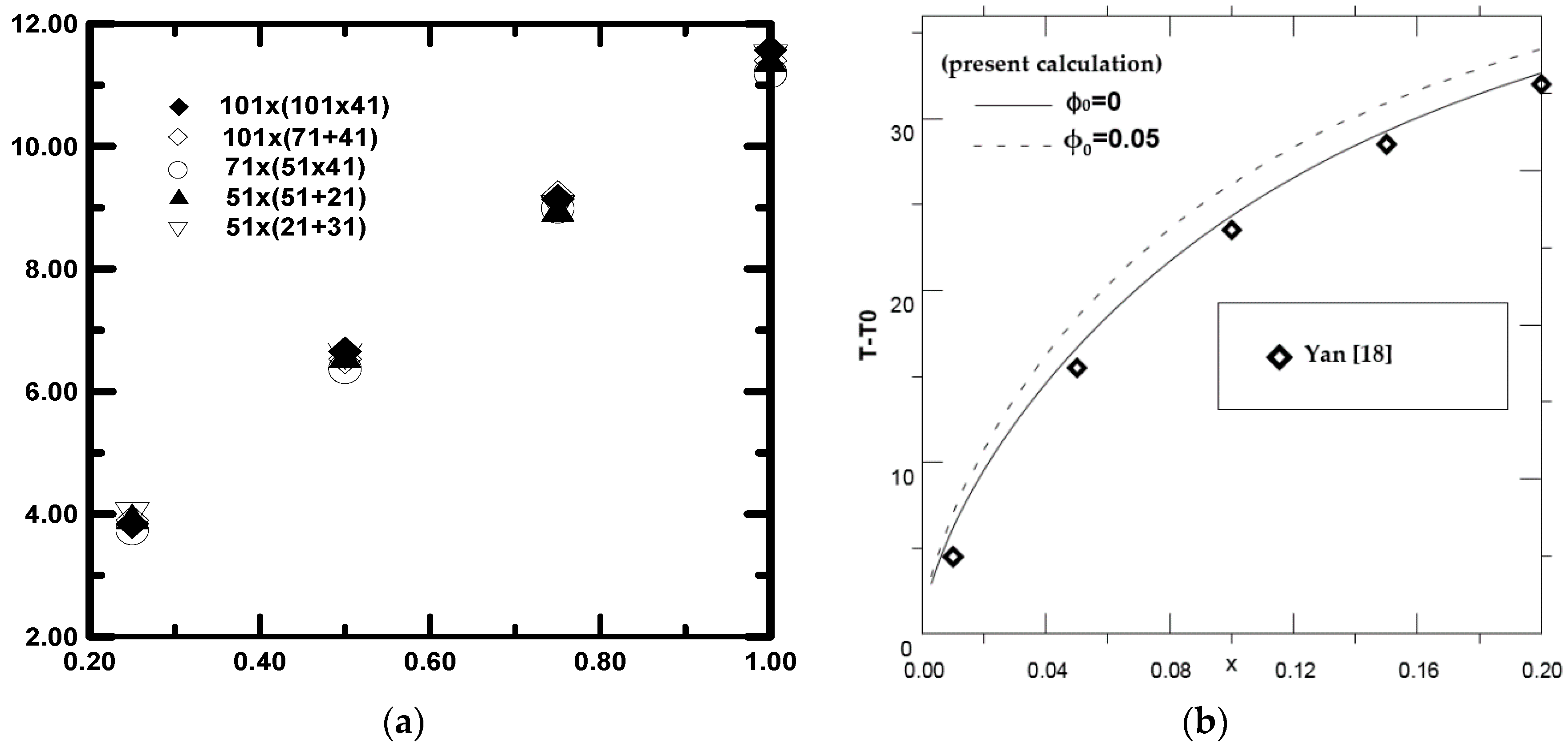
The system of partial differential Equations (1)–(17) is solved using the implicit finite difference method. The governing partial differential equations are transformed into finite difference equations by using a fully implicit marching scheme. The system of finite difference equations is solved by the Gaussian elimination method. To confirm that results were grid-independent, Table 1 presents the stability of calculation from a mesh variations-local evaporation rate   m ( X ) . Table 1 and Figure 2a show that the difference in the local evaporation rate obtained using 101 × (101 + 41) and 51 × (21 + 31) grids is less than 1%. To validate the numerical simulation used in the present work, a comparison between our results of the interfacial temperature (Ti − T0) during pure water film evaporation flowing down a vertical heated plate by mixed convection, and those obtained by Yan [18], has been effected. This comparison has been made for q2 = 0, T0L = 298 K, T0 = 293 K, q1 = 3000 W/m2, Re = 2000,   m 0 L = 0.02 Kg / s , d = 0.015 m. Figure 2b shows a satisfactory agreement.

3. Results and Discussion

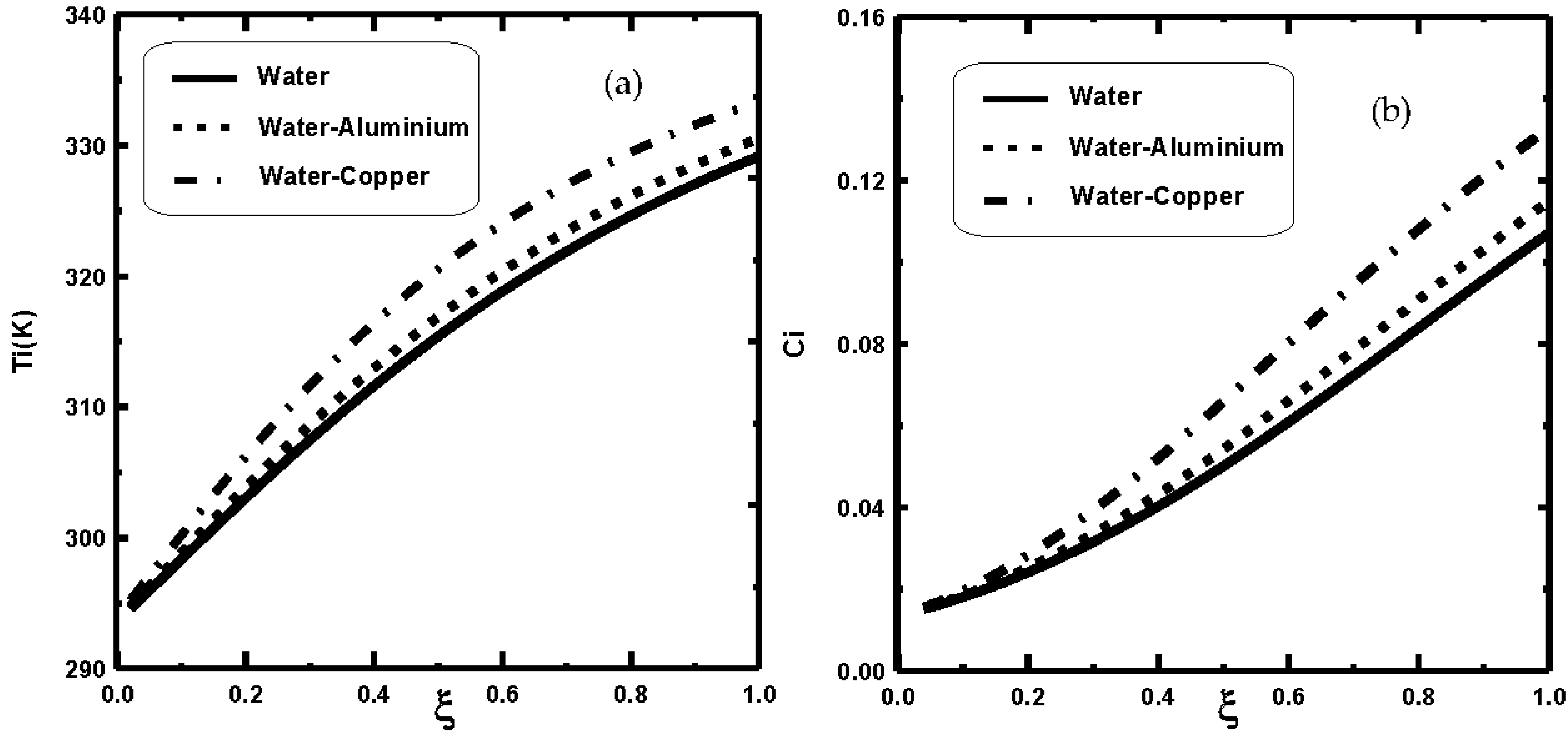
The present work focuses on the evaporation of nanofilm (water + copper nanoparticles) falling on a vertical channel by mixed convection. The falling plate was subjected to uniform flux while the other plate was isothermal and dry. In this work, we show the impact of nanoparticle types and their volume fraction φ0 on mass and heat exchange and on film evaporations. Figure 3 illustrates the impact of nanoparticle types on the interfacial liquid–vapour temperature and vapour concentration. Figure 3a shows that the interfacial liquid–vapour temperature of the water–copper (H2O-Cu) nanofluid is greater than that of water–aluminium (H2O-Al) nanofluid. This variation in the interfacial temperature may be due to the elevated thermal conductivity and the lower heat capacity of copper nanoparticles compared to those of the aluminium nanoparticles.
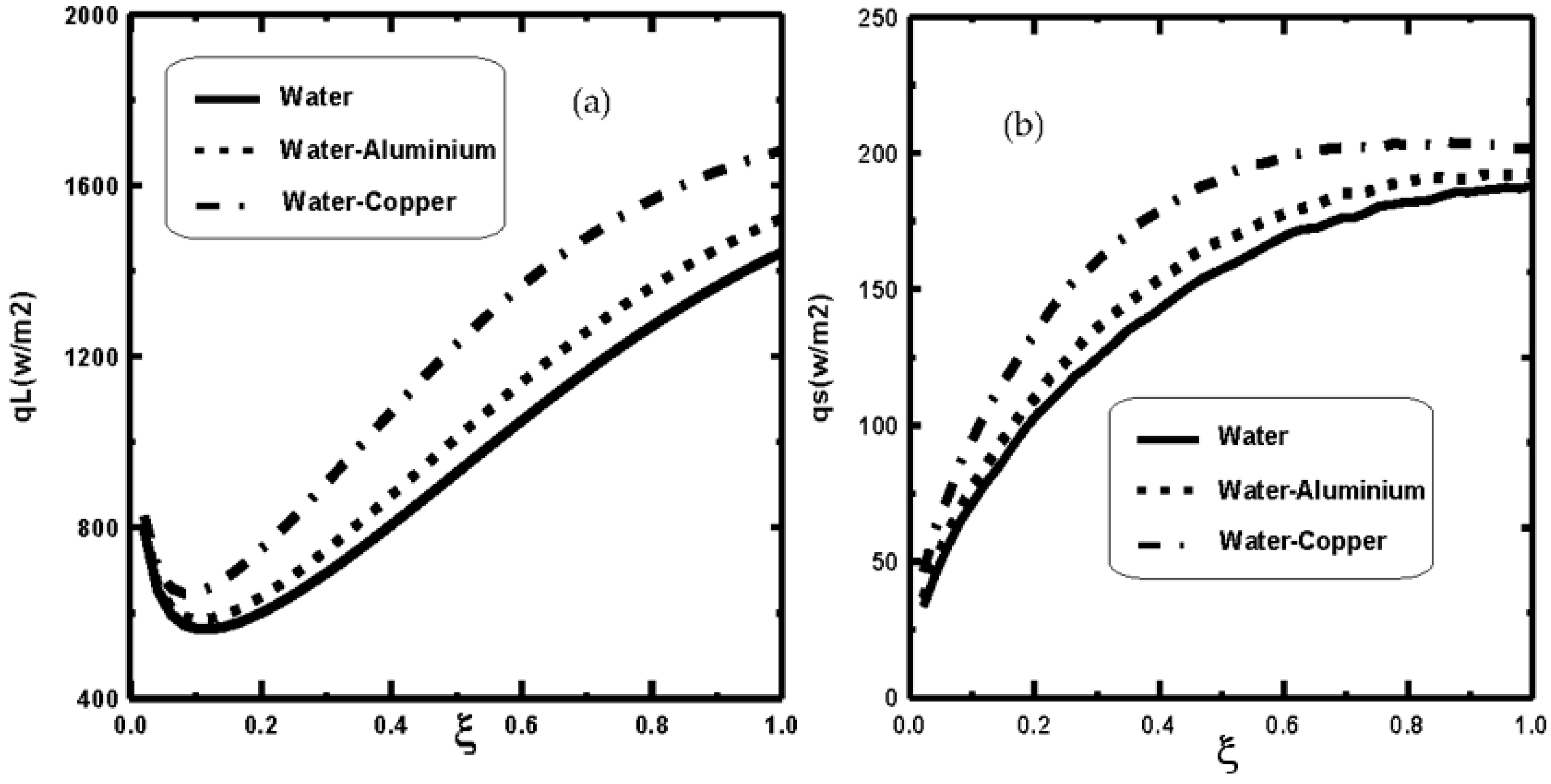
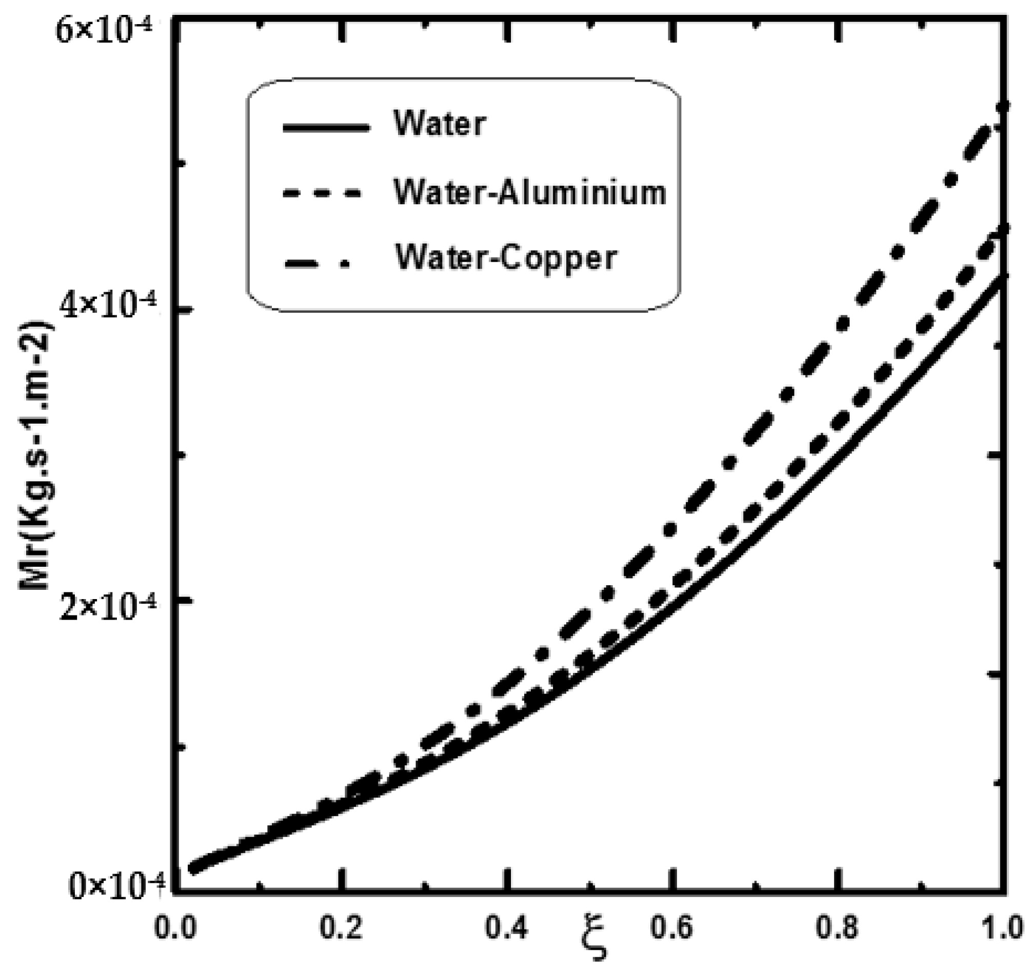
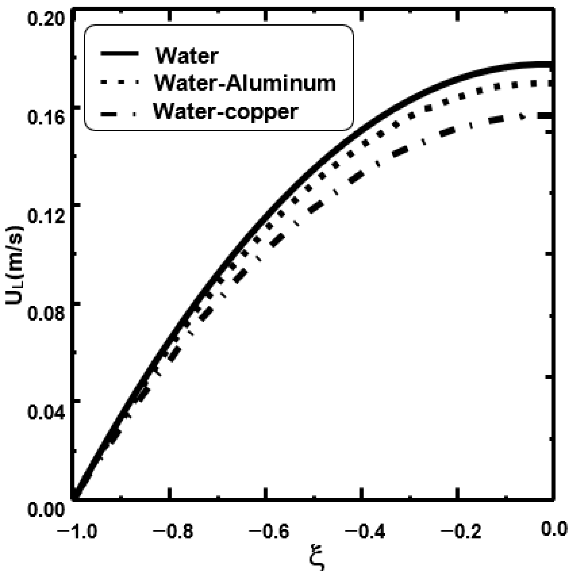
Figure 4a,b presents the sensible and latent heat fluxes for various nanofluids and for pure water. It is shown that the heat transfer is more enhanced with the dispersion of copper nanoparticles than with aluminium nanoparticles and water film. This is can be explained by the lower heat capacity and higher thermal conductivity of copper nanoparticles compared to aluminium nanoparticles and water film (see Table 2). This is explained by the fact that the latent heat flux is enhanced by using the nanofluids (see Figure 4b). Figure 5 shows that the liquid film evaporation was higher for copper–water nanofluid compared to aluminium–water nanofluid and pure water. Figure 6 displays the variation of the velocity of the liquid at the channel exit for various types of nanoparticles types. It was found that the velocity of the liquid for copper–water nanofluid was lower compared to water–aluminium nanofluid and to basic fluid (water). This is due to the increase in the viscosity of nanofluid compared to base-fluid (water).
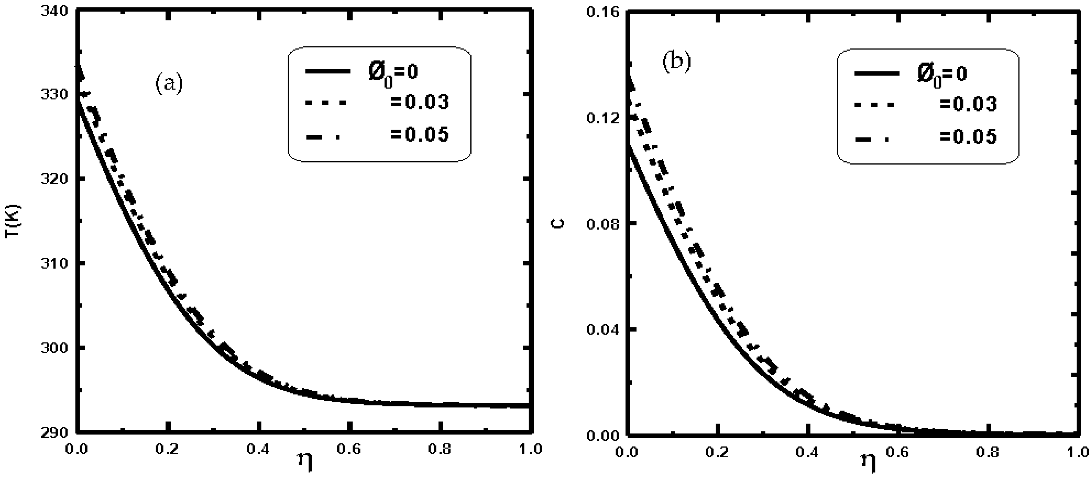
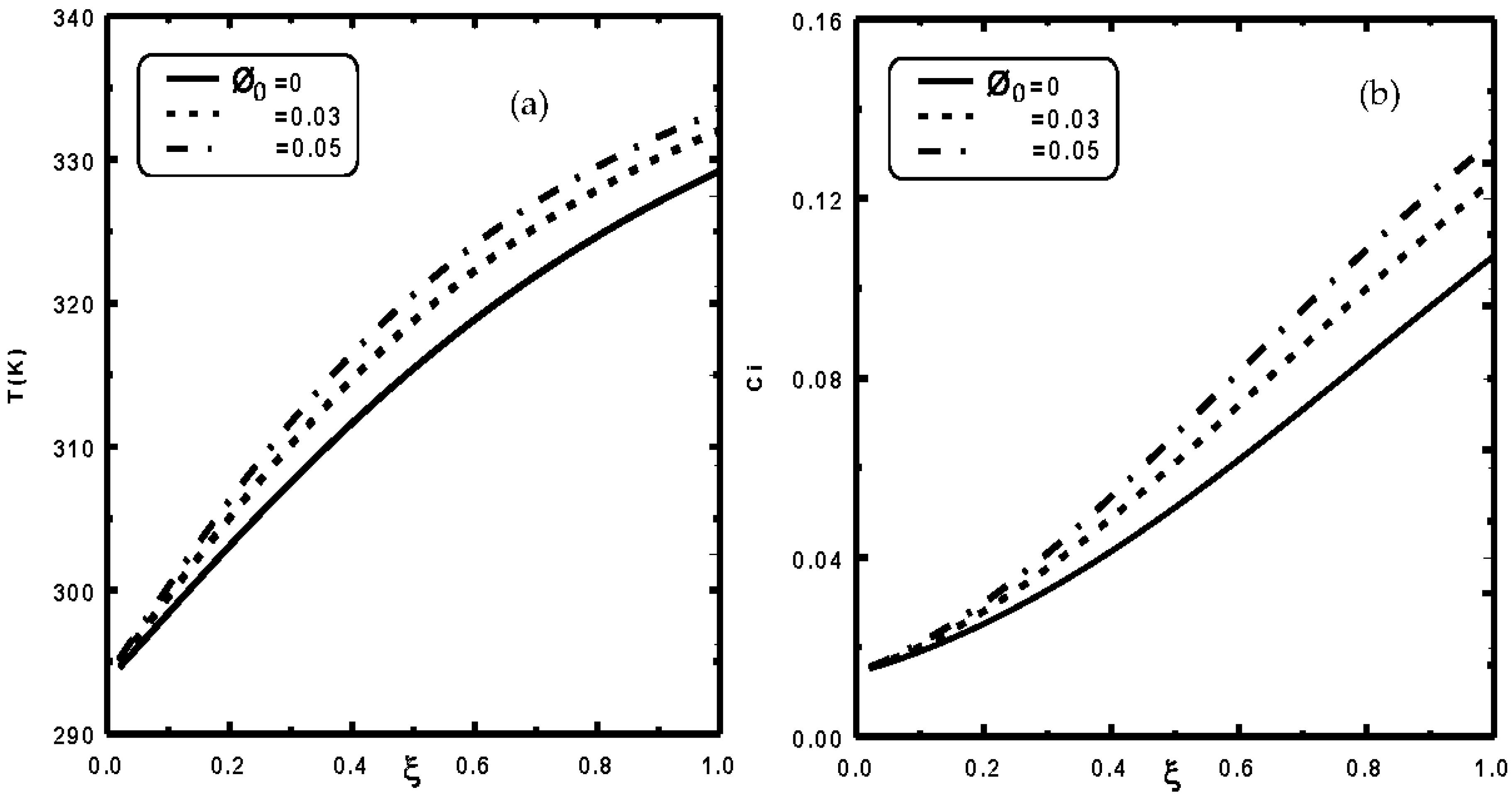
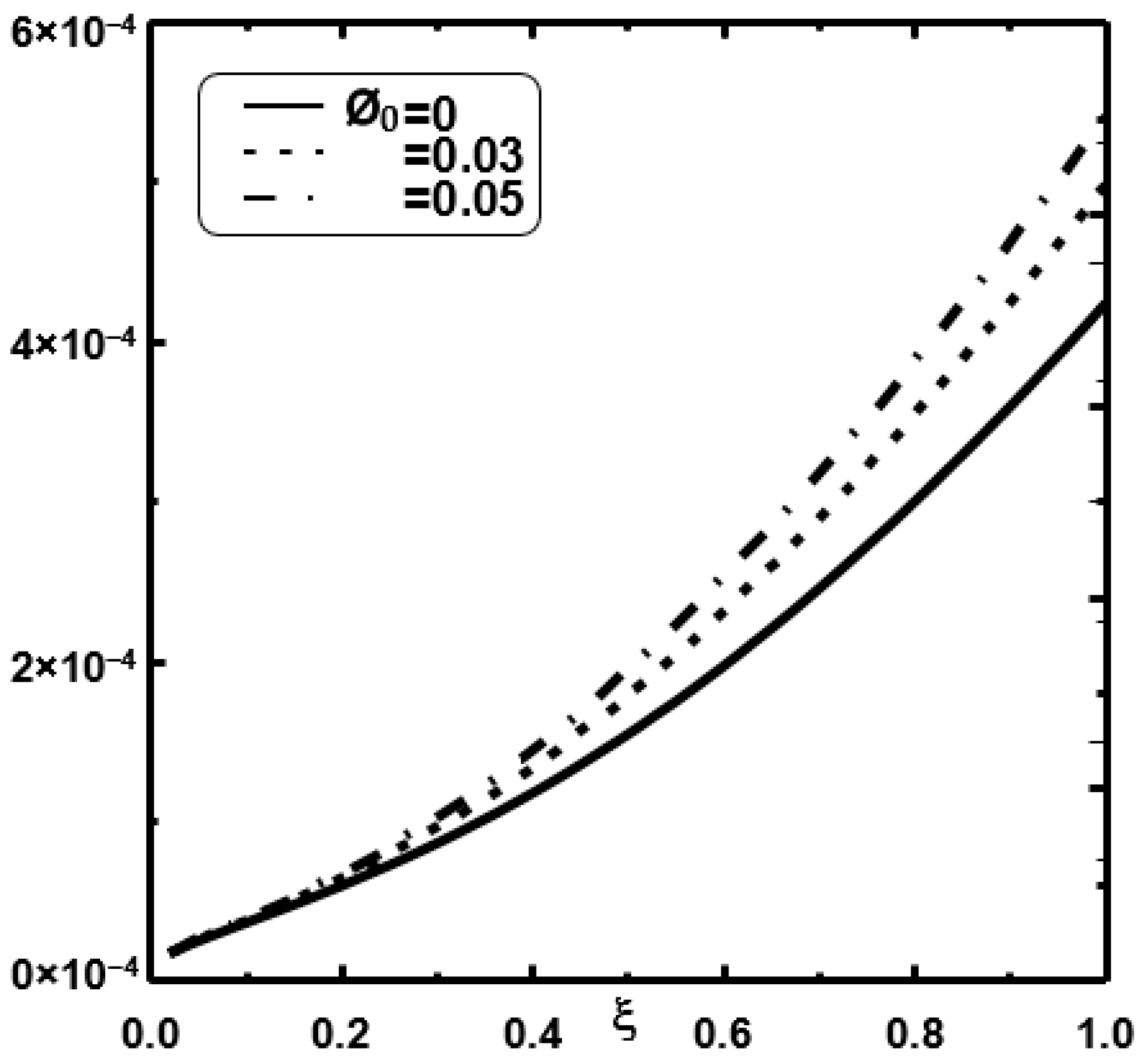
Figure 7 and Figure 8 illustrate the effect of the copper volume fraction φ0 on the temperature and vapour concentration at the interface of liquid–vapour and in the gas mixture. Figure 7a and Figure 8a show that the temperature is important for high values of φ0. This result may be due to the high thermal conductivity and the lower heat capacity of nanoparticles compared to pure water. Figure 7b and Figure 8b show that the increase of φ0 causes an increase in the vapour concentration in the gas region. This result is justified by the fact that an augmentation of the temperature causes an increase in the vapour concentration in the gas region. It is also shown in Figure 4b that the concentration gradient is increased when φ0 is augmented, causing an improvement of the vapour mass transfer (Fick’s law). In fact, the addition of nanoparticles increases heat transfer in the liquid, which allows more energy to be transferred to the liquid–vapour interface; increasing the number of water molecules evaporating from the surface induces an increase in water film evaporation (Figure 9). In fact, Figure 9 shows an enhancement of the evaporative heat transfer efficiency of liquid nanofilms compared to liquid pure liquid films. This result is very important because the enhancement of water film evaporation occurs only by the dispersion of copper nanoparticles in the liquid film and without an increase in the energy consumption.
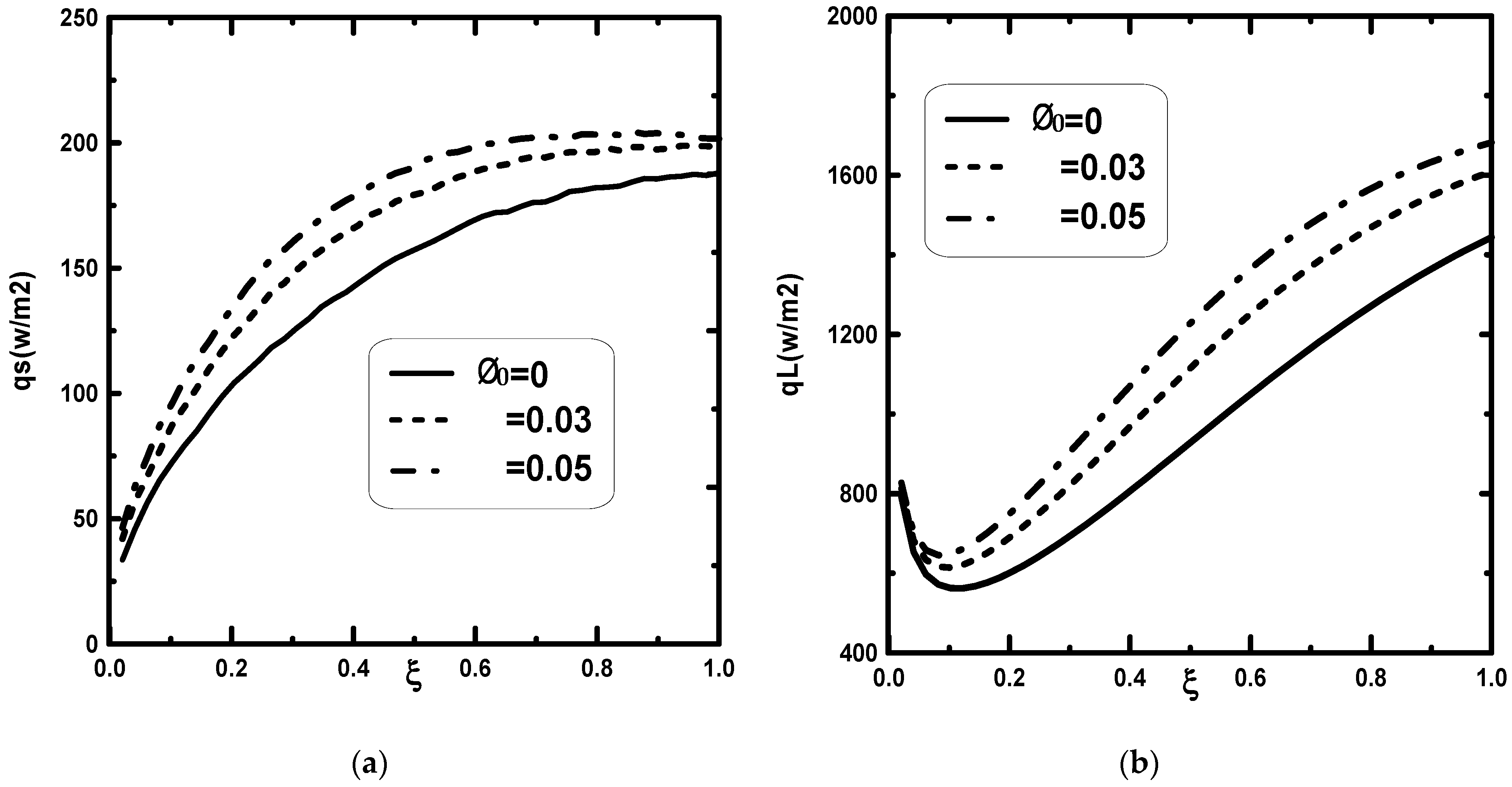
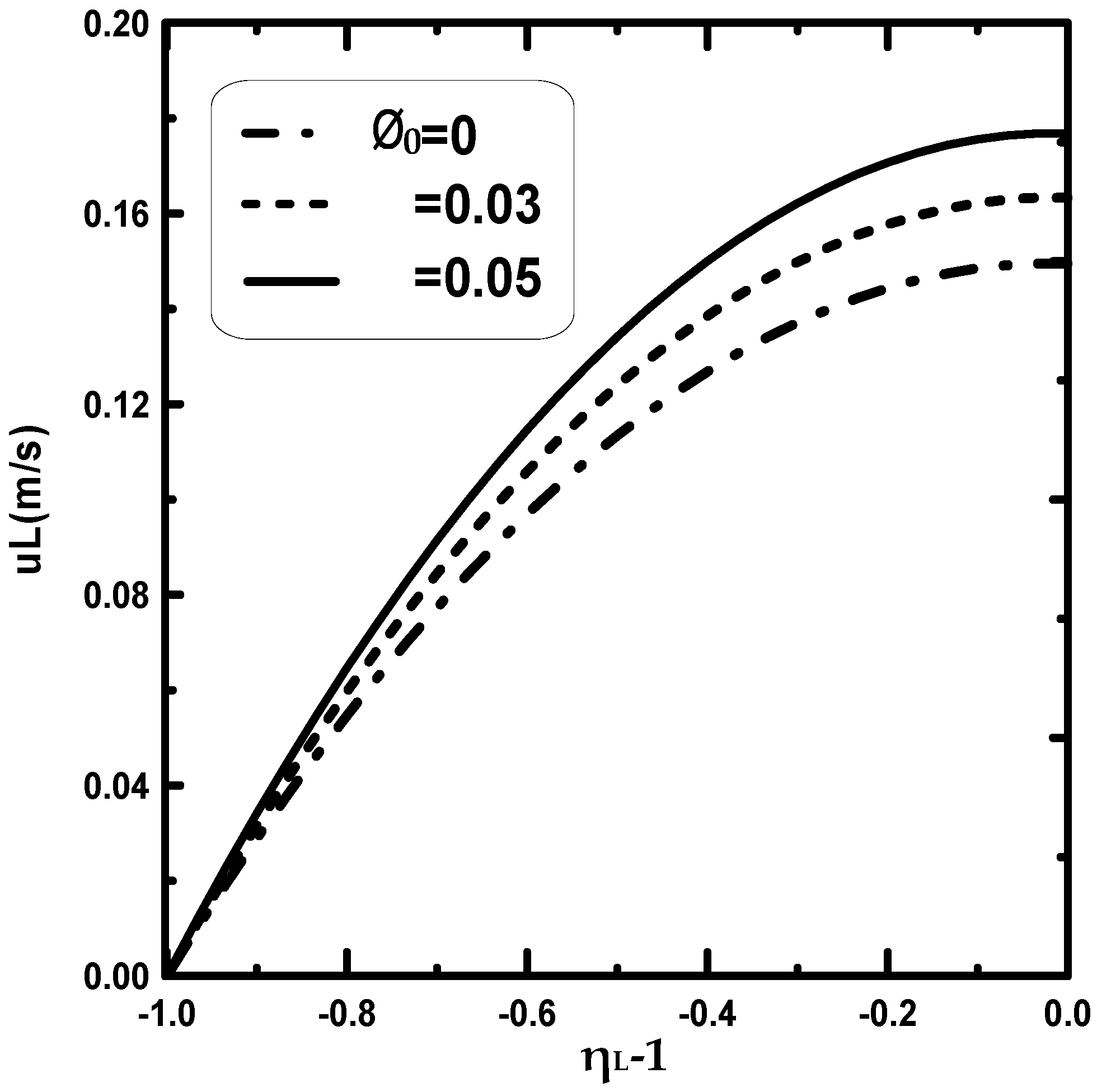
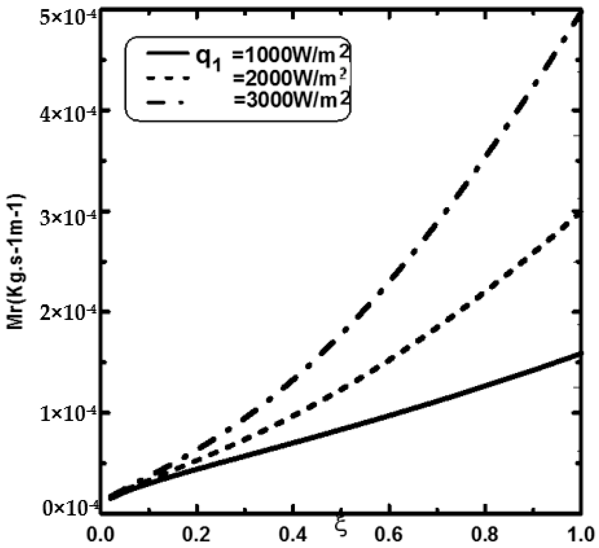
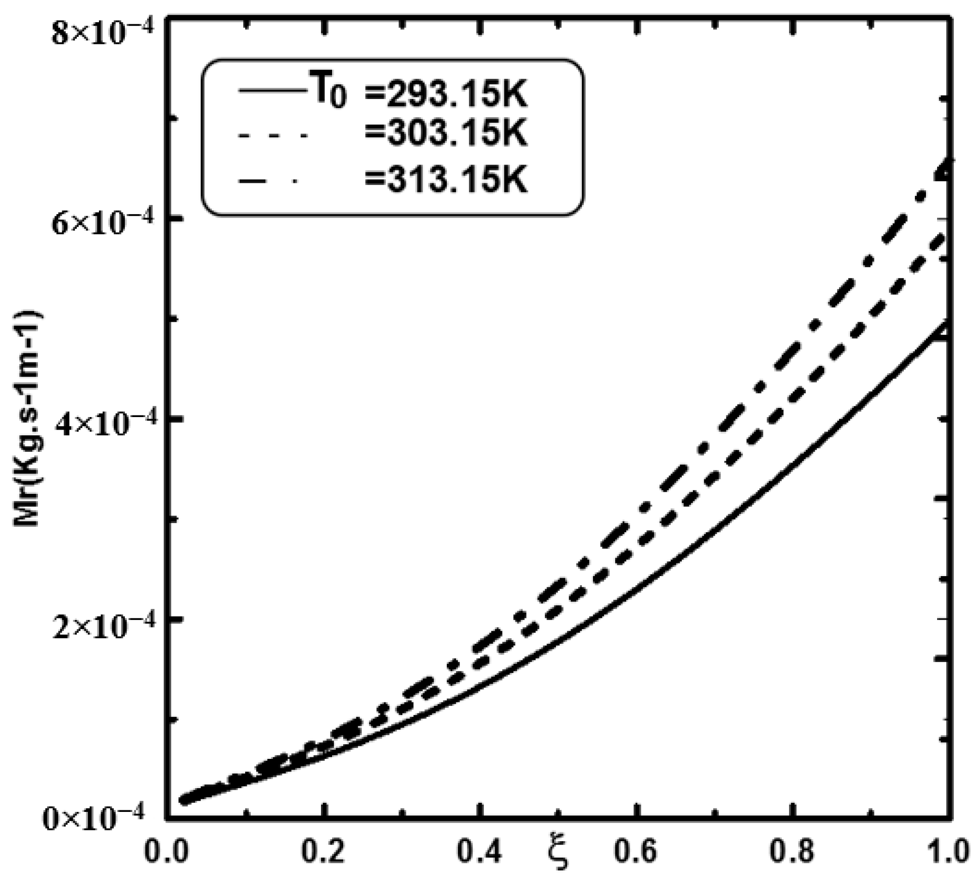
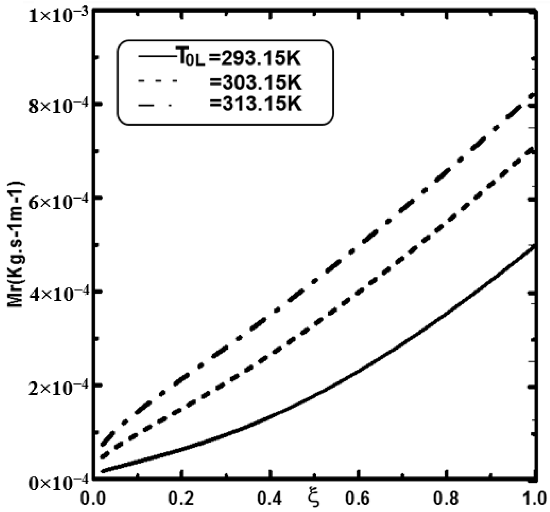
Figure 10a,b illustrates the sensible and latent heat fluxes for various values of φ0. Figure 9 shows that the latent and sensible heat transfer was enhanced if we dispersed the copper nanoparticles into the water film. In fact, it is shown that an increase of φ0 causes an increase in the latent (Figure 10a) and sensible (Figure 10b) heat fluxes. In Figure 10b, the decreasing of the latent heat flux near the plate entrance is explained by the fact that the liquid film near the plate entrance is sufficiently heated to convect the heat to the gas and the heat transfers in this region are dominated by sensible heat. Far from the plate entrance, the latent heat flux increase and the heat transfer are dominated by latent heat. Figure 11 illustrates the evolution of the velocity of the liquid for various φ0. It is found that an augmentation of φ0 reduces the velocity of the liquid at the channel exit. We can explain this by the fact that an augmentation of φ0 induces an increase of the nanofluid viscosity compared to the base fluid (water), causing a deceleration of liquid film flow. It is shown in Figure 12 that the fluid film evaporation rate is raised for important values of external heat flux qw. Figure 13 concludes that the film evaporation becomes more critical for higher values of T0. This result is explained by the fact that increasing T0 induces an increase in the temperature at the liquid–gas interface and consequently an increase of the vapour concentration at the liquid–gas interface, causing an augmentation of film evaporation. Figure 14 illustrates the impact of liquid temperature T0L on the liquid film evaporation rate. In fact, it is shown that an increase in the inlet film temperature ameliorates the film evaporation.

4. Conclusions

A numerical investigation of the evaporation of nanofilms of copper–water and aluminium–water flowing on a channel by mixed convection has been presented. The channel was composed of two parallel vertical plates. The wetted plate was heated while the other plate was maintained dry and isothermal. The impact of the dispersion of different nanoparticles and their volume fractions on the efficiency of heat exchange and on the evaporation process has been analysed.
The following conclusions are drawn:
(1).
The dispersion of nanoparticles improves the mass and heat exchange during film evaporation.
(2).
It is shown that the dispersion of copper nanoparticles enhances liquid film evaporation more compared to aluminium nanoparticles and pure water.
(3).
It is shown that the liquid film evaporation rate is increased with an increase of nanoparticle volume fraction Φ0.
(4).
It is shown that an enhancement of 22% in evaporation rate has been recorded when the nanoparticle volume fraction Φ0 of copper is elevated by 5%.
(5).
It is observed that an increase in the inlet gas ameliorates the water film evaporation.
(6).
An increase in the inlet liquid temperature improves the water film evaporation.
(7).
An increase in the supplied heat flux enhances the water film evaporation.

Author Contributions

Conceptualization, A.N.; Data curation, A.N.; Formal analysis, A.N.; Writing—original draft, A.N.; Writing—review & editing, A.A.A. All authors have read and agreed to the published version of the manuscript.

Funding

The authors would like to thank the Deanship of Scientific Research at Umm Al-Qura University for supporting this work by Grant Code: (22UQU4340531DSR02).

Institutional Review Board Statement

Not applicable.

Informed Consent Statement

Not applicable.

Data Availability Statement

Not applicable.

Conflicts of Interest

The authors declare no conflict of interest.

Abbreviation

Nomenclature
cmass fraction for water vapour
Dmass diffusivity [m2·s−1]
Pdynamic pressure in the channel [N·m−2]
Tabsolute temperature [K]
uaxial velocity [m·s−1]
vtransverse velocity [m·s−1]
xcoordinate in the axial direction [m]
ycoordinate in the transverse direction [m]
Greek symbols
φvolume fraction of nanoparticles
λthermal conductivity of the fluid [W·m−1·K−1]
μdynamic viscosity of the fluid [kg·m−1·s−1]
ρdensity of the gas [kg·m−3]
ηdimensionless coordinate in the transverse direction
ξdimensionless coordinate in the flow direction
Subscripts
nnanoparticle
psolid particle
fNanofluid
Lliquid

References

  1. Do, K.H.; Jang, S.P. Effect of nanofluids on the thermal performance of a flat micro heat pipe with a rectangular grooved wick. Int. J. Heat Mass Transf. 2010, 53, 2183–2192. [Google Scholar] [CrossRef]
  2. Zhao, J.-J.; Duan, Y.-Y.; Wang, X.-D.; Wang, B.-X. Effect of nanofluids on thin film evaporation in microchannels. J. Nanoparticle Res. 2011, 13, 5033–5047. [Google Scholar] [CrossRef]
  3. Namburu, P.K.; Das, D.K.; Tanguturi, K.M.; Vajjha, R.S. Numerical study of turbulent flow and heat transfer characteristics of nanofluids considering variable properties. Int. J. Therm. Sci. 2009, 48, 290–302. [Google Scholar] [CrossRef]
  4. Sefiane, K.; Bennacer, R. Nanofluids droplets evaporation kinetics and wetting dynamics on rough heated substrates. Adv. Colloid Interface Sci. 2009, 147–148, 263–271. [Google Scholar] [CrossRef]
  5. Gorjaei, A.R.; Soltani, M.; Bahiraei, M.; Kashkooli, F.M. Cfd simulation of nanofluid forced convection inside a three-dimensional annulus by two-phase mixture approach: Heat transfer and entropy generation analyses. Int. J. Mech. Sci. 2018, 146–147, 396–404. [Google Scholar] [CrossRef]
  6. Asirvatham, L.G.; Vishal, N.; Gangatharan, S.K.; Lal, D.M. Experimental Study on Forced Convective Heat Transfer with Low Volume Fraction of CuO/Water Nanofluid. Energies 2009, 2, 97–119. [Google Scholar] [CrossRef] [Green Version]
  7. Chen, R.-H.; Phuoc, T.X.; Martello, D. Effects of nanoparticles on nanofluid droplet evaporation. Int. J. Heat Mass Transf. 2010, 53, 3677–3682. [Google Scholar] [CrossRef]
  8. Siddiqa, S.; Begum, N.; Hossain, M.; Gorla, R.S.R.; Al-Rashed, A.A. Two-phase natural convection dusty nanofluid flow. Int. J. Heat Mass Transf. 2018, 118, 66–74. [Google Scholar] [CrossRef]
  9. Sheremet, M.A.; Cimpean, D.S.; Pop, I. Free convection in a partially heated wavy porous cavity filled with a nanofluid under the effects of Brownian diffusion and thermophoresis. Appl. Therm. Eng. 2017, 113, 413–418. [Google Scholar] [CrossRef]
  10. Malvandi, A.; Heysiattalab, S.; Ganji, D. Thermophoresis and Brownian motion effects on heat transfer enhancement at film boiling of nanofluids over a vertical cylinder. J. Mol. Liq. 2016, 216, 503–509. [Google Scholar] [CrossRef]
  11. Orejon, D.; Sefiane, K.; Shanahan, M.E.R. Evaporation of nanofluid droplets with applied DC potential. J. Colloid Interface Sci. 2013, 407, 29–38. [Google Scholar] [CrossRef] [PubMed] [Green Version]
  12. Orejon, D.; Sefiane, K.; Shanahan, M.E.R. Stick–Slip of Evaporating Droplets: Substrate Hydrophobicity and Nanoparticle Concentration. Langmuir 2011, 27, 12834–12843. [Google Scholar] [CrossRef] [PubMed]
  13. Askounis, A.; Sefiane, K.; Koutsos, V.; Shanahan, M.E.R. The effect of evaporation kinetics on nanoparticle structuring within contact line deposits of volatile drops. Colloids Surf. A Physicochem. Eng. Asp. 2014, 441, 855–866. [Google Scholar] [CrossRef]
  14. Perrin, L.; Pajor-Swierzy, A.; Magdassi, S.; Kamyshny, A.; Ortega, F.; Rubio, R.G. Evaporation of Nanosuspensions on Substrates with Different Hydrophobicity. ACS Appl. Mater. Interfaces 2018, 10, 3082–3093. [Google Scholar] [CrossRef]
  15. Abu-Hamdeh, N.H.; Abdulmalik, A.A.; Eltaher, M.A.; Almitani, K.H.; Alnefaie, K.A.; Abusorrah, A.M.; Safaei, M.R. Implicit Finite Difference Simulation of Prandtl-Eyring Nanofluid over a Flat Plate with Variable Thermal Conductivity: A Tiwari and Das Model. Mathematics 2021, 9, 3153. [Google Scholar] [CrossRef]
  16. Mashhour, A.A.; Nidal, H.A.; Goodarzi, M. Entropy Optimization of First-Grade Viscoelastic Nanofluid Flow over a Stretching Sheet by Using Classical Keller-Box Scheme. Mathematics 2021, 9, 2563–2585. [Google Scholar]
  17. Kam, O.R.; Bakouan, C.; Zongo, I.; Guel, B. Removal of Thallium from Aqueous Solutions by Adsorption onto Alumina Nanoparticles. Processes 2022, 10, 1826. [Google Scholar] [CrossRef]
  18. Yan, W.M. Effects of film evaporation on laminar mixed heat and mass transfer in a vertical channel. Int. J. Heat Mass Transf. 1992, 12, 3419–3429. [Google Scholar]
  19. Huang, X.G.; Yang, Y.H.; Hu, P. Experimental study of falling film evaporation in large scale rectangular channel. Ann. Nucl. Energy 2015, 76, 237–242. [Google Scholar] [CrossRef]
  20. Palen, J.W.; Wang, Q.; Chen, J.C. Falling film evaporation of binary mixtures. AICHE J. 1994, 40, 207–214. [Google Scholar] [CrossRef]
  21. Brinkman, H.C. The viscosity of concentrated suspensions and solutions. J. Chem. Phys. 1952, 20, 571. [Google Scholar] [CrossRef]
  22. Maxwell, J.C. A Treatise on Electricity and Magnetism; Clarendon Press: Oxford, UK, 1881; Volume 1. [Google Scholar]
  23. Rosenhain, W. The Properties of Some Copper Alloys (Classic Reprint) Paperback–October 27, 2017; Forgotten Books: London, UK, 2017. [Google Scholar]
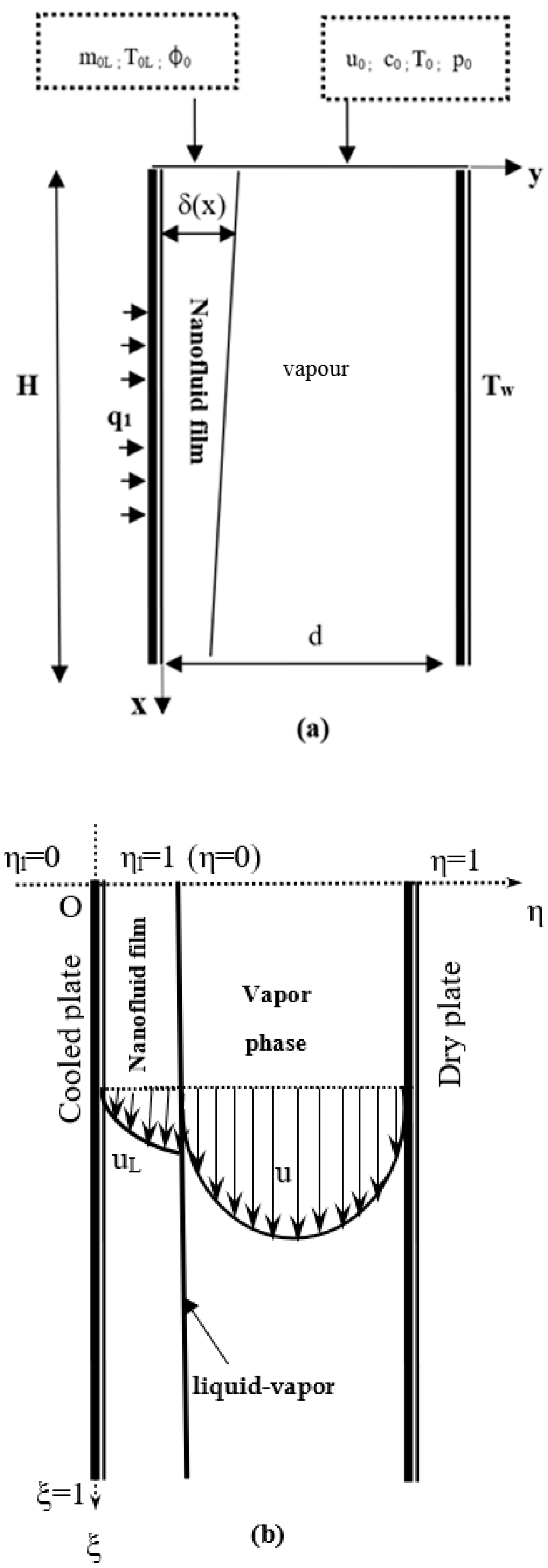
Figure 1. (a) Schematic diagram of physical system of heat exchanger; (b) Domain of the physical system of heat exchanger.
Coatings 12 01564 g001
Figure 2. (a) The grid independence study; (b) Comparison of the temperature at the interface with Yan [18].
Coatings 12 01564 g002
Figure 3. Effect of nanoparticles type on the temperature (a) and the vapour mass fraction (b) at the interface liquid-gas: T0 = 20 °C, T0L = 20 °C, q1 = 3000 W/m2, Tw = 20 °C, c0 = 0, u0 = 1 m/s, m0L = 15 × 10−4 Kg/m·s, p0 = 1 atm, d/H = 0.015, φ0 = 0.05.
Coatings 12 01564 g003
Figure 4. Effect of nanoparticles type on the latent ql (a) and sensible qs (b) heat fluxes: T0 = 20 °C, T0L = 20 °C, q1 = 3000 W/m2, Tw = 20 °C, c0 = 0, u0 = 1 m/s, m0L = 15 × 10−4 Kg/m·s, p0 = 1 atm, d/H = 0.015, φ0 = 0.05.
Coatings 12 01564 g004
Figure 5. Effect of nanoparticles type on the cumulated evaporation rate: T0 = 20 °C, T0L = 20 °C, q1 = 3000 W/m2, Tw = 20 °C, c0 = 0, u0 = 1 m/s, m0L = 15 × 10−4 Kg/m·s, p0 = 1 atm, d/H = 0.015, φ0 = 0.05.
Coatings 12 01564 g005
Figure 6. Effect of nanoparticles type on the liquid velocity at the exit channel: T0 = 20 °C, T0L = 20 °C, q1 = 3000 W/m2, Tw = 20 °C, c0 = 0, u0 = 1 m/s, m0L = 15 × 10−4 Kg/m·s, p0 = 1 atm, d/H = 0.015, φ0 = 0.05.
Coatings 12 01564 g006
Figure 7. Effect of nanoparticle volume fraction on the temperature (a) and the vapor concentration (b) at the channel exit: T0L = 293.15 K, T0 = 293.15 K, q1 = 3000 W/m2, c0 = 0, Tw = 293.15 K, u0 = 1 m/s, H = 1 m, d = 0.015 m, m0L = 15 × 10−4 Kg/m·s, p0 = 1 atm.
Coatings 12 01564 g007
Figure 8. Variation of the temperature (a) and vapour concentration (b) at the interface liquid-gas for different nanoparticle volume fraction: T0L = 293.15 K, T0 = 293.15 K, q1 = 3000 W/m2, c0 = 0, Tw = 293.15 K, u0 = 1 m/s, H = 1 m, d = 0.015 m, m0L = 15 × 10−4 Kg/m·s, p0 = 1 atm.
Coatings 12 01564 g008
Figure 9. Effect of nanoparticle volume fraction on the total evaporation rate: T0L = 293.15 K, T0 = 293.15 K, q1 = 3000 W/m2, c0 = 0, Tw = 293.15 K, m0L = 15 × 10−4 Kg/m·s, u0 = 1 m/s, H = 1 m, d = 0.015 m, p0 = 1 atm.
Coatings 12 01564 g009
Figure 10. Impact of φ0 on the sensible qs (a) and latent ql heat fluxes (b): T0L = 293.15 K, T0 = 293.15 K, q1 = 3000 W/m2, Tw = 293.15 K, c0 = 0, u0 = 1 m/s, m0L = 15 × 10−4 Kg/m·s, H = 1 m, d = 0.015 m, p0 = 1 atm.
Coatings 12 01564 g010
Figure 11. Evolution of the liquid velocity at the exit channel for different values of nanoparticle volume fraction: T0L = 293.15 K, T0 = 293.15 K, c0 = 0, q1 = 3000 W/m2, m0L = 15 × 10−4 Kg/m·s, Tw = 293.15 K, u0 = 1 m/s, H = 1 m, d = 0.015 m, p0 = 1 atm.
Coatings 12 01564 g011
Figure 12. Evolution of the cumulated evaporation rate to various heat flux: T0L = 293.15 K, T0 = 293.15 K, u0 = 1 m/s, Tw = 293.15 K, m0L = 15 × 10−4 Kg/m·s, H = 1 m, d = 0.015 m, c0 = 0, p0 = 1 atm, φ0 = 0.03.
Coatings 12 01564 g012
Figure 13. Variation of the cumulated evaporation rate to various inlet gas temperature: T0L = 293.15 K, q1 = 3000 W/m2, Tw = 293.15 K, c0 = 0, p0 = 1 atm, m0L = 15 × 10−4 Kg/m·s, H = 1 m, d = 0.015 m, u0 = 1 m/s, φ0 = 0.03.
Coatings 12 01564 g013
Figure 14. Evolution of the cumulated evaporation rate to various inlet liquid temperature: T0 = 293.15 K, c0 = 0, q1 = 3000 W/m2, Tw = 293.15 K, u0 = 1 m/s, p0 = 1 atm, m0L = 15 × 10−4 Kg/m·s, H = 1 m, d = 0.015 m, φ0 = 0.03.
Coatings 12 01564 g014
Table 1. Stability of calculation in mesh variations local water film evaporation rate.
I × (J + K) Grid Point101 × (101 + 41)101 × (71 + 41)71 × (51 + 41)51 × (51 + 21)51 × (21 + 31)
ξ = 0.253.8413.9003.9733.9593.736
ξ = 0.506.6516.5306.5726.5936.367
ξ = 0.759.1409.2008.9848.9868.959
ξ = 1.0011.57311.40011.44211.42511.195
Table 2. Thermo-physical properties of the base fluid and of nanoparticles at T = 300 K.
Thermo-Physical PropertiesAluminiumCopper (Cu)
ρ (kg·m−3)27008933
Cp (J·kg−1·K−1)900385
λ (W·m−2·K−1)240401
Publisher’s Note: MDPI stays neutral with regard to jurisdictional claims in published maps and institutional affiliations.