Abstract
In order to study the bond-slip constitutive model between prestressed tendons and concrete, the pull-out tests of single-strand and multi-strands specimens are carried out. The effect of the number of prestressed tendons on the failure mode, slip characteristics and concrete strain of the pull-out specimens are analyzed, and the constitutive models of bond-slip between for single- strand and multi-strand tendons are also proposed. The results show that the bond mechanism between steel strand and concrete is basically similar to that of deformed steel bar, but the slip process of steel strand along the axis direction is accompanied by rotation phenomenon because it is twisted. Moreover, compared with the single-strand prestressed tendon, the average ultimate bond stress of each tendon of the three-strand prestressed tendons decreases by 13.2%. In addition, the calculated result of the pull-out limit load for the single-strand prestressed tendon is only 2% higher than the experimental value, while the corresponding value of three-strand prestressed tendon is only 3.74% lower than the experimental value. This means that the proposed bond-slip models for single- strand and multi-strand tendons have high reliability.
1. Introduction
The effective bond between strand and concrete is the basis for the work of bonded prestressed concrete beams [1]. With the increase of service time of post-tensioned prestressed concrete (PTPC) structures, the long-term erosion of concrete by carbon dioxide and chlorine elements, as well as construction defects such as insufficient grouting, can lead to strand corrosion or even local fracture. For PTPC beams after local fracture of the strand, an effective bond between the strand and the concrete is the primary factor that allows it to continue to work properly. The prestressing tendons achieve secondary anchorage through the bond between them and the concrete [2,3]. Therefore, under the premise of the end anchorage failure of PTPC beam or the local prestressed tendon fracture, it is important to study the bond performance of multiple tendons in the prestressing tendon to accurately estimate the bearing capacity of the structure.
Some scholars have conducted experimental studies on the bonding performance of single strands and proposed a model for bonding performance measurement of single strands. Mohandoss [4] emphasized that the existing test methods to determine the bond strength in rebar-concrete systems cannot be used for strand-concrete systems, and the failure of strand-concrete depend on the failure of concrete keys, which is a function of shear strength of concrete and interlocking effects due to the helical shape of the strands. Franceschini [5] proposed a new constitutive law (CPS-model) to predict the mechanical behavior of prestressing strands induced by pitting corrosion. Wang [6] investigated the bond-slip property of high-strength stainless steel strand in engineered cementitious composites (ECC) with tensile strength, steel strand diameter and relative anchorage length, and established the bond-slip relationship model between steel strand and ECC according to the improved BPE model. Dai [7] predicted the transfer length in pre-tensioned concrete beams according with corrosive cracking. Dyba [8,9] developed a finite element analysis method for bond stresses in prestressing tendons. However, most of the above research only focused on single prestressed reinforcement. The bond mechanism between multi-bar prestressed steel strands and concrete is not clear, and the corresponding bond-slip model has not been proposed.
It is different from the single prestressing tendon that the bond performance at the interface between the prestressing bundle and the compression slurry is inevitably influenced by the interaction of the individual tendon. As a result, the bonding behavior of prestressing bundles as a combination of multiple prestressing tendons is more complex. In view of the above problems, some scholars have gradually paid attention to the effect of the number of prestressed steel strands on the bond-slip performance. Zghayar [10] found that the bond performance between the prestressing bundle and the compression slurry is greatly influenced by the number of prestressing forces as well as the arrangement density. For prestressing FRP tendons, Zhang [11] found a non-uniform bonding force problem between the interface of multiple force tendons and the compression slurry. Wu [12] investigated the effect of temperature on bond strength and found that the bond strength deteriorated with a rise in temperature and the degradation of bond strength was more severe than that of other mechanical properties. Zhu [13] studied the influence laws of spacing between transverse stainless-steel strand, diameter of longitudinal stainless-steel strand and relative anchorage length on the bond properties of steel strand in ECC. The test results show that the bond failure can be transformed from brittle failure to ductile failure by adding the transverse steel strands. Mei [14] studied the bond-slip behavior of CFRP tendons inside anchors and multiaxial stresses of the steel sleeve, and the test results shown that bond-slip relationship of CFRP tendon inside anchor is nonlinear. Most of the above studies focus on prestressed steel tendons not used for bridges, which leads to doubts about the applicability of existing conclusions in ordinary PC structures. Therefore, it is urgent to study the bond performance between multi-bar prestressed steel strands and concrete.
The main purpose of this paper is to study the bonding performance between multi-bar prestressed tendons and concrete. First, the pull-out test of single-strand and multi-strands specimens are carried out. Next, the effect of the number of prestressed tendons on the damage mode, specimen slip characteristics and concrete strain is analyzed, and the bond mechanism of multi strand tendons is also revealed. Finally, the local bond-slip constructive model for single-bar and multi-strand tendons are further established, and the effectiveness of the above model is also verified. Among them, studying the bond mechanism of multi-bar prestressed tendons and proposing a bond-slip constructive model for multi-bar prestressed tendons are the novelties of this paper.
2. Test Introduction
2.1. Specimen Design
Two pull-out specimens, numbered as PLS1 and PLS2, are designed in this test according to the specification of JTG 3362-2018 [15]. The section forms of the above specimens are set as rectangle to match the actual rectangular beam. To avoid splitting failure of the two specimens, the lengths of specimens are designed as 1000 mm, and the ratio between the concrete cover and the diameter of steel strand are set to be greater than 5. In addition, the cross-sectional dimensions of the two specimens are set as 300 mm × 500 mm according to the commonly used size range of rectangular section. PLS1 is a single-bar specimen for comparison and its prestressed bar is a single 7-wire twisted steel strand of . PLS2’s prestressed bars are three 7-wire twisted steel strands of . Eight HRB400 deformed bars with 12 mm is configured longitudinally as erection bars, and the HPB235 plain round bars with 8 mm is selected as stirrups with a spacing of 100 mm. The steel strands are placed in the center of the specimen section. The detailed dimension and reinforcement layout of these specimens are as shown in Figure 1 and Figure 2.
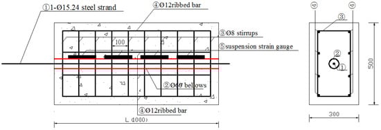
Figure 1.
Dimension and reinforcement of specimen PLS1.
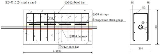
Figure 2.
Dimension and reinforcement of specimen PLS2.
The HRB 400-grade ribbed bars with a diameter of 16mm and 10mm are arranged in the tension area and compression area, respectively. The HPB235 plain round bars with a diameter of 8 mm is selected as stirrups. The 1860-grade 7-wire steel stands with a diameter of 15.2 mm is adopted as the prestressed steel bars. The yield strength, limit strength, elasticity modulus, and elongation of the above reinforcement and steel strand have been tested according to the specification of GB/T228.1-2021 [16] and the test method used in Wang et al. [17], and the test results are shown in Table 1.

Table 1.
Mechanical properties of steel bars.
The concrete specimens are manufactured using C425 ordinary silicate cement. The natural river sand is used as fine aggregate, the graded gravel is used as coarse aggregate with a maximum nominal particle size of 25 mm, and the tap water mixed from the laboratory is used. The mix proportion of specimens is cement: sand: gravel: water = 1:1.62:2.73:0.44. The mortar is the commercial cement paste of the same grade as concrete, and the tension stress of sand-steel strand is 1395 MPa. Material properties of the steel strands and the ordinary steel bars are shown in Table 1. The two test components are cast with the same batch of concrete at one time, so the concrete compression strength of each specimen is the same. The standard cube specimen is made of the same batch of concrete and cured together with the test components. The average compressive strength of concrete in 28 days is 56.5 MPa.
2.2. Test Devices and Monitoring Point Arrangement
According to the test rules of the bond stress between concrete and steel strands, draw-off gear is self-designed. After the test components are completed, a center hole jack with a range of 150 tons is used for tensioning and the pull-out force is measured by rope meter.
Since the steel strands in the test are made by twisting seven wires, the axis of the steel strands cannot be slotted, or strain gauge cannot be pasted on their surface to monitor the strain of the steel strands because of the twisting angle. Therefore, suspension strain gauges are placed at the outer wall of the corrugated pipes with a spacing of 17.5 cm in order to monitor the strain of concrete and calculate strain distribution and real-time bond length of the steel strands. In the test, free end and loading end of the specimens are both installed with a dial indicator to record the relative slippage between steel strands and concrete. Distribution of the strain gauges and the devices for the pull-out test are shown in Figure 3.
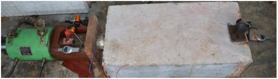
Figure 3.
Devices for the pull-out test.
Pre-tensioning is carried out before formal tensioning to eliminate inelastic deformation between test devices, and the pre-tensioning force is set as 5 kN. After that, a step-by-step loading method is adopted here. The initial loading is 5kN for each stage, and the load for each stage is adjusted to 15 kN after reaching 15 kN. When the steel strand is pulled out or broken, as well as the slip at the loading end is large and the load cannot continue to increase or the increment is very small, the specimen is considered as bond slip failure. That is, the pull-out test has been completed.
3. Test Results and Analysis
3.1. Damage Mode
In the test process, PLS1 and PLS2 are both strand fractures, and when the two specimens reached 1000 mm, they both have sufficient bond lengths. The maximum bond strength of the steel strands provided by concrete is larger than the ultimate tensile strength of the strands.
For PLS1 steel strand, its slippage at the free end is close to zero, almost nonexistent. All steel wires of PLS1 steel strand are basically broken at the same time, and there is no splitting failure of concrete or overall pull-out of steel strand. However, the increase rate of the slippage at the tension end of PLS2 steel strand is much faster than that of PLS1 steel strand, and the slippage at the free end also increased rapidly. Finally, the steel strand is necked and then pulled to failure, as shown in Figure 4. Neither of the two specimens has splitting failure, so it can be considered that the specimens have sufficient thickness of protective layer.
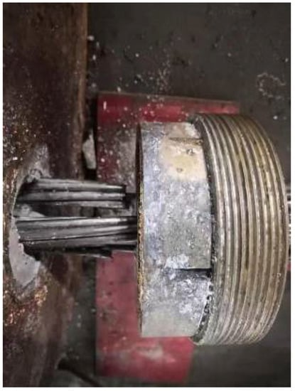
Figure 4.
Steel strand pull-off damage.
3.2. Slip Performance under Load
In the pull-out test, the steel strands slipped in a way that is not consistent with that of ordinary deformed steel bars and twisted along the steel strands. This is similar to the screw-out mode of a long stud, namely, the spiral slippage. The reason should be related to the fact that the steel strands are formed in a twisted way, so the strands slipped not only in a linear way but also a rotary way, which is similar to long studs and the pitch should be the distance of twist. This proves that the twisted steel strands slipped through the concrete in a way such as removing a stud along the nut. However, different from the greater ductility of the real nuts are made of metal materials, concrete nuts are made of fragile materials and their threads are easier to break, which results in the weakened rotational confinement effect and further the direct slippage between the steel strands and concrete. Meanwhile, with the increase of load, after each rotary slippage, the load will decrease to a certain extent. As the load continues to be increased, the undamaged concrete threads will work again, and then the load will continue to be increased, resulting in a sawtooth shape on the load-slip curve. The concrete that occurred and worked as nuts was of fragile material, and its thread is easily damaged by twisted wires of the steel strands. The total slippage of the steel strands is composed of linear slippage and rotary slippage. The linear slippage means the slippage of the steel strands in their direct pull-out along the axis, while rotary slippage means the slippage at an end during the strand rotation. Therefore, the bond and cementation effect are gradually destroyed, and after the loss of cementation, the bonding force is mainly composed of the friction force between the concrete and the steel strands and the bite force between the steel wires in the twisting direction.
Figure 4 shows the load-slip curves of loading and free ends of PLS1 and PLS2. For specimen PLS1, when the drawing force gradually increases, the slip increases. When the drawing force is less than 90 kN, the slip value has a linear relation with the increase of the drawing force, then there is a nonlinear relation between the value of the drawing force and the slip of the loading end. The increasing speed of the slip is obviously greater than that of the drawing force. Finally, the drawing force increases slowly, while the slip value increases rapidly, and the steel strands are broken. At the same time, almost no slip at the free end is measured during the whole drawing process. Since the steel strands are broken and their maximum load corresponds to their ultimate tensile strength, and the cementation of the concrete and the steel strands at the free end is not damaged yet, the maximum bonding force provided by the specimens is inevitably greater than the ultimate tensile strength of the steel strands.
As indicated in Figure 5, the load-slip curve of a single-wire steel strand is not consistent with that of a three-wire steel strand, specimen PSL2 slips at the free end and has a sawtooth shape at the loading end. Therefore, the effective bond length of PLS2 is obviously larger than that of PLS1. Meanwhile, from the load-slip curves of PLS1 and PLS2, it can be drawn that their ultimate drawing loads are, respectively, 262 kN and 776 kN. These two specimens have effective bond performance, and the effective bond length is less than the designed length. The reason is that for the tendons, the concrete cracking areas around each wrapped steel strand overlap each other due to the small spacing of the multiple steel strands, and the micro-cracks become wider, and the cracking range is obviously larger than that of a single-strand component. According to the thick cylinder theory, the concrete with multi-strand components cracked in a single tendon cannot provide the wall thickness of a single strand in a single tendon and thus cannot provide enough binding force to the steel tendon, resulting in the reduction of mechanical interaction and friction force, and the bonding stiffness and strength smaller than those of a single-strand component, so a longer bonding length is needed.
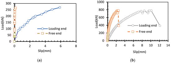
Figure 5.
Load-slip curves of the drawing specimens. (a) PLS1; (b) PLS2.
3.3. Concrete Strain Distribution
By recording the strains of the suspension strain gauge for each specimen under different drawing load and drawing lines according to their distribution, the concrete strains at different distances from the loading end are obtained, as shown in Figure 6. In the test, the strain is assumed to be uniformly distributed along the whole cross section, without considering the influence of its uneven distribution at the same cross section. It can be seen from Figure 6 that with the pull-out force, the strain distribution of concrete is non-uniform and nonlinear along the specimen length, the line slope between two adjacent strains under a same load and the slope between two identical points under different pull-out forces are both different. When the pull-out force is small, the value of the concrete strain near the loading end is very big, and with the increase of the pull-out force, concrete strain is gradually transferred to the free end and the strain becomes smaller gradually from the loading end to the free end. These two specimens suffer significantly different drawing loads when the initial strain occurs at the free end. For PLS1, its strain at the free end is zero under ultimate load, and for PLS2, when the drawing load increases to 200 kN, some negative strains at the free end and even the concrete turn into tiny positive strains. From Figure 5, it may be concluded that the effective length of PLS1 under the ultimate load is 88 cm and that of PLS2 is 100 cm.
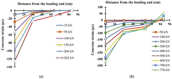
Figure 6.
Concrete strain distribution under pull-out load. (a) PLS1; (b) PLS2.
3.4. Average Bond Stress
It can be inferred from Figure 6 that the distribution of bond stress is not uniform along the length of the specimen. In order to discuss the influence of the number of steel strands on the bond stress, it can be assumed that the bond stress is consistent in the range of the bond length. Therefore, the average bond stress may be calculated through Equation (1)
where: is average bond stress, P is pull-out force, is effective bond length, and is total circumference of steel strands.
According to Equation (1), the average bond stress of PLS1 under the ultimate pull-out force is 6.23 MPa, and that of PLS2 is 5.41 MPa, reduced by 13.2%. It can be drawn that both stiffness and average bond strength of the three-strand specimen decrease significantly, compared with those of single-strand specimen.
4. Local Bond-Slip Model of Steel Strand Tendons
4.1. Local Bond-Slip Model of Steel Strands
For the local bond-slip performance of deformed bars, many scholars in the world have developed lots of bond-slip curve models, which are generally simplified as multi-segment broken-line or curvilinear model. The most used one is four-segment local bond-slip model recommended by the CEB-FIP Code [18], which, as shown in Figure 7, is divided into four segments including nonlinear increase, linear segment, linear decrease, and constant residual bond. In Figure 7, is splitting bond stress, is ultimate bond stress and is residual bond stress. s1, s2, and s3 are the slip values corresponding to .
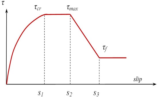
Figure 7.
Local bond-slop model under CEB-FIP Code.
In order to simplify the calculation, many scholars [19,20] have ignored this part in model building. Considering that the bond stiffness and strength of steel strands are composed of adhesive force, mechanical friction force and biting force and so are those of the deformed steel bars, in the calculation of this paper, the CEB-FIP Model may be improved by removing the linear segment, and the local bond-slip model may be used in the calculation of PLS1, which can be expressed as Figure 8 and Equation (2).
where is maximum bond stress, and is compressive strength of concrete. is residual bond strength, and its value is set as . x1 is local slip under the maximum bond stress, x2 is local slip under the residual friction and bond stress. According to the calculation method proposed by Haskett [21] and Zhang [19], x1 is taken as 3 mm and x2 is taken as 12 mm. α is a constant parameter and is taken as 0.4.
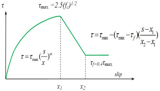
Figure 8.
Local bond-slip model for PLS1.
4.2. Analysis Method of Local Bond-Slip Model for a Single Steel Strand
According to Equation (1), if x1 and x2 are determined, the local bond-slip relation between a single strand of a single strand tendon and concrete can be determined if the maximum bond stress is determined. The bond-slip relation is calculated by assuming the value of the maximum bond stress . The calculated curve and the test value are compared with each other repeatedly in order to correct the maximum bond stress , until the difference between the two curves meet the accuracy requirements.
Divide specimen PLS1 into n pieces of girder elements and number them as 1, … i … n consecutively. For a simple calculation, set all elements with a same length of 10mm. In addition, considering the very minimal girder length, assume that all girder elements have the same force and slip. With , calculate the local bond-slip relation between steel strands and concrete according to Equation (1) and then acquire sp, the slip value at the loading end under pull-out force P. Collect strain gauge readings and determine the effective transfer length in the girders, that is, both concrete strain and steel strand slip at the end of the effective length are zero, see Figure 9 for the calculation diagram. The specific calculation process is as follows:
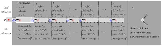
Figure 9.
Calculation diagram of specimen PLS1.
- (1)
- Set the slip value at the loading end under the pull-out force P as , and calculate s1, the slip value of element 1 of the bond segment of the specimen according to load and deformation relation.
- (2)
- Set pull-out force as and the slip value of 1 of element 1 as , and repeatedly calculate the local bond stress of this element with prepared bond-slip constructive model according to the amount of slip, and calculate local load increment according to equation ( is the sum of the circumference of the cross section of steel strand).
- (3)
- Since all elements are very short, it can be assumed that all elements are subject to the same force. Calculate the strand strain of element 1# () and concrete strain (), in which and are, respectively, the sectional area of steel strands and concrete of specimen PLS1, Es and Ec are, respectively, the elasticity modulus of steel strands and concrete of specimen PLS1.
- (4)
- Calculate the relative slip of steel strands and concrete of element 1 .
- (5)
- Calculate the stress of steel strands of element 2 ().
- (6)
- Calculate the amount of slip of element 2 ().
In the same way, the pull-out force Fi and slip si of the steel strands of any ith element can be calculated. Since the slip at the free end of PLS1 is zero, its boundary conditions may be set that if both the pull-out force and slip of an element in the specimen meet the accuracy requirements, the assumed is considered correct, otherwise, should be reset, until the boundary condition error is within the allowable range.
Based on results of the pull-out test, the boundary conditions may be divided into two types. The first one is that when the load is relatively small, no slip occurs at the free end, the length of bond transfer is less than the length of the entire specimen and the boundary condition is that the pull-out force Fi and slip si of the steel strands of a certain element in the specimen are both 0. The second one is that when the drawing load is relatively great, the pull-out force exists along the whole specimen length and slip occurs at the free end, the boundary condition is that the pull-out force Fn of the steel strands at element n at the free end is 0.
And according to the test results, the failure of the specimens is the fracture of steel strands, so elastoplastic deformation should be considered for the strand strain, namely
where is yield strength of the steel strands, is corresponding yield strain, is strain-hardening modulus after yield, is strain of the steel strands at ith element, and Fi is pull-out force of the steel strands at ith element.
In view of compressive property of concrete, some scholars have pointed out that when the pressure stress is within 40% of the compressive strength, concrete may be regarded as linear elastic material, without considering nonlinear effect of the material. The maximum pull-out force F withstood by the steel strands in the test is about 262 kN, so the maximum pressure stress withstood by corresponding concrete is about 3 MPa. The standard value of axial compressive strength of concrete (fck) can be calculated according to the conversion relationship between it and the concrete cubic compressive strength (fcu = 56.5 MPa) provided by the code of GB 50010-2020 [22], and its value is 36.7 MPa.
4.3. Validation of Constitutive Model of a Single-Strand Specimen
According to the calculation and analysis method stated in Section 4.2, calculate the load-slip curve of the loading end of specimen PLS1 of a single-strand prestressed tendon. By calculation, is set as .
The load-slip calculation curve of loading end is calculated based on Equation (3) and (which is set as ), as shown in Figure 10. As indicated, the calculated value of pull-out limit load is 262 kN, which is only 2% higher than the experimental value of 257 kN. That is, the calculation results are in good agreement with the experimental result. By calculation, the boundary condition is determined as the first type and it can be confirmed that the failure mode of the steel strand is consistent with the actual test results, namely, tensile failure. Therefore, it may be concluded that the local bond-slip model amended according to CEB-FIP code as proposed in Equation (3) has relatively high calculation accuracy.
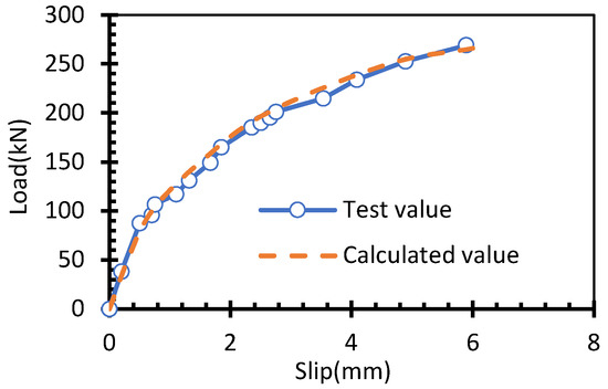
Figure 10.
Comparison of the measured and calculated load-slip curves of the loading end of specimen PLS1.
4.4. Local Bond-Slip Model of Three-Strand Prestressed Specimen
According to the CEB-FIP Code [17], the three-strand prestressed specimen should have similar local bond-slip model of concrete and steel strands as the single-strand prestressed specimen. Based on the bond mechanism, the interaction between the multi-strand tendons and concrete is much complex and the bond between the multi-strand tendons and grouting interface is inevitably affected by the interaction of all bars. When the spacing of each strand is small, the extent of micro-cracks in some concrete around the steel strand increases and the constraint on the steel strands decreases, so the interaction of multiple steel strands may not only affect the bond strength between steel strands and concrete, but also affect the bond stiffness, which is in inverse proportion to the number of strands. From Equation (1), it can be seen that may affect both the bond stiffness and strength, therefore, the bond-slip model of the steel strands can be adjusted simply by correcting the value of . For this purpose, this paper explored the local bond characteristics of three steel strands and concrete simply by correcting the value of .
Similar to determining the bond-slip model of a single steel strand and concrete, a calculation was made with trial method for the bond-slip constructive model of the three-strand specimen PLS2 and a bond-slip curve of the loading end was obtained. The difference from the calculation process of PLS1 is that the first type of boundary condition is taken when no slip occurs at the free end of PLS2, or otherwise, the second type of boundary condition may be taken, that is, the pull-out force Fn of the steel strands at element n# at the free end is 0, and in specific calculation. The first step is to set the maximum bond stress according to the method in Section 4.2, successively calculate the pull-out force and slip value of each strand element. For Nth element, if the pull-out force meets the accuracy requirement, the setting is feasible, otherwise, the calculation should be re-made by correcting . The comparison between the load-slip curve of the loading end calculated with this method and the measured curve is as shown in Figure 11. By comparison, it can be drawn that for specimen PLS2, the calculated values are all in good agreement with the test values under all grades of load by correcting , and coincide with actual test results, and the steel strands are broken. This shows that it is reasonable and feasible to represent the local bond characteristics of steel strands and concrete by correcting . See Equation (4) for the corrected bond-slip constructive model.
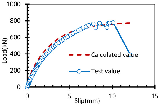
Figure 11.
Comparison of measured and calculated load-slip curves of PLS2.
By calculation, see Equation (4) for the corrected bond-slip constructive model.
where is set as , , n is the number of steel strands.
According to Equation (4), the load-slip curve of the loading end of PLS2 was calculated by setting n as 3. The calculated curve and the measured curve are as shown in Figure 11. As indicated, the calculated value of pull-out limit load is 747 kN, which is 3.74% lower than the test value of 776 kN. The prediction deviation fully meets the engineering prediction requirements. Moreover, the failure mode of the drawing specimens obtained after calculation was the fracture of steel strands, in agreement with test results. Therefore, it can be drawn that by introducing the number of the steel strands as a parameter, the corrected local bond-slip model of the concrete and steel strands has relatively high calculation accuracy.
5. Conclusions
In this paper, the effect of the number of prestressed tendons on the failure mode, slip characteristics and concrete strain of the pull-out specimens are analyzed, and the constitutive models of bond-slip between for single-bar and multi-strand tendons are also proposed. The conclusions are summarized as follows:
- (1)
- The bond mechanism between steel strands and concrete is basically similar to that of deformed steel bars, but the slip process of steel strand along the axis direction is accompanied by rotation phenomenon because it is twisted.
- (2)
- Three-strand prestressed tendons have a smaller bond stress than those of single-strand prestressed tendons. In this test, the mean ultimate bond stress of three-strand prestressed tendons is about 13.2% smaller than that of single-strand prestressed tendons.
- (3)
- Based on load-slip data of the loading end of single-strand prestressed tendons, the maximum bond strength can be determined by a trial calculation with the model suggested by CEB-FIP code.
- (4)
- A simplified bond-slip constructive model between three strand prestressing tendons and concrete is proposed. The bond force is degraded exponentially according to the number of strands that make up the prestressing tendon. The validity of the proposed model is verified by comparing the experimental results with the predicted values.
The limitation of this study is that only two kinds of strand quantities are considered, and the effect of more types of strand quantities on the bond performance needs to be further studied. Moreover, the effect of tendon configurations with different numbers but the same total area on the bond performance is also the focus of future research.
Author Contributions
Conceptualization, R.Y.; methodology, R.Y.; X.Z. and X.W.; validation, R.Y. and Y.Y.; writing—original draft preparation, R.Y. and Y.Y.; writing—review and editing, R.Y., Y.Y., X.Z. and X.W.; supervision, X.Z. and X.W.; funding acquisition, R.Y. and X.W.; All authors have read and agreed to the published version of the manuscript.
Funding
This research was funded by the Hunan Provincial Natural Science Foundation of China (grant no. 2021JJ50156 and 2021JJ50153), and the Research Foundation of Education Bureau of Hunan Province (grant no. 18A401 and 19C0343).
Institutional Review Board Statement
Not applicable.
Informed Consent Statement
Not applicable.
Data Availability Statement
Not applicable.
Conflicts of Interest
The authors declare that they have no known competing financial interests or personal relationships that could have appeared to influence the work reported in this paper.
References
- Dang, C.N.; Hale, W.M.; Martí-Vargas, J.R. Quantification of bond performance of 18-mm prestressing steel. Constr. Build. Mater. 2018, 159, 451–462. [Google Scholar] [CrossRef]
- Dai, L.Z.; Xu, W.G.; Wang, L.; Yi, S.C.; Chen, W. Secondary transfer length and residual prestress of fractured strand in post-tensioned concrete beams. Front. Struct. Civ. Eng. 2022, 16, 388–400. [Google Scholar] [CrossRef]
- Yang, R.H.; Zhang, J.R.; Wang, L.; Zhang, X.H. Experimental research for flexural behavior on concrete beams with local corrosion fracture of strands. J. Cent. South Univ. (Sci. Technol.) 2018, 49, 2593–2601. [Google Scholar]
- Mohandoss, P.; Pillai, R.G.; Gettu, R. Determining bond strength of seven-wire strands in prestressed concrete. Structures 2021, 33, 2413–2423. [Google Scholar] [CrossRef]
- Franceschini, L.; Vecchi, F.; Tondolo, F.; Belletti, B.; Sánchez Montero, J. Mechanical behaviour of corroded strands under chloride attack: A new constitutive law. Constr. Build. Mater. 2022, 316, 125872. [Google Scholar] [CrossRef]
- Wang, X.L.; Zhao, Y.K.; Zhou, Q.W.; Zhu, J.T. Study on bond-slip property of high strength stainless steel strand and ECC. J. Huazhong Univ. Sci. Technol. (Nat. Sci. Ed.) 2020, 48, 108–113. [Google Scholar]
- Dai, L.Z.; Chen, H.; Wang, L.; Ma, Y.F.; Zhang, J.R. Transfer length prediction in pre-tensioned concrete beams under corrosive cracking. Structures 2021, 30, 938–948. [Google Scholar] [CrossRef]
- Dyba, M. FEM Simulations of Bond Behaviour between Concrete and Seven-Wire Prestressing Strand. IOP Conf. Ser. Mater. Sci. Eng. 2020, 960, 032076. [Google Scholar] [CrossRef]
- Dyba, M. FEM Analysis of Bond between Concrete and Seven-Wire Prestressing Strand. IOP Conf. Ser. Mater. Sci. Eng. 2020, 960, 032077. [Google Scholar] [CrossRef]
- Zghayar, E.E.; Mackie, K.R.; Haber, Z.B.; Potter, W. Secondary Anchorage in Post-Tensioned Bridge Systems. ACI Struct. J. 2013, 110, 629–638. [Google Scholar]
- Zhang, K.Y.; Fang, Z.; Nanni, A. Behavior of Tendons with Multiple CFRP Rods. J. Struct. Eng. 2016, 142, 04016065. [Google Scholar] [CrossRef]
- Wu, X.Q.; Huang, T.; Zhang, L.; Au, F.T.K. Bond performance of grouted tendons at elevated temperatures. ICE Proc. Struct. Build. 2021, 174, 791–803. [Google Scholar] [CrossRef]
- Zhu, J.T.; Zhang, K.; Wang, X.L.; Li, K.; Li, Y. Bond-slip relational model between high-strength stainless steel wire mesh and ECC. China Civ. Eng. J. 2020, 53, 83–92. [Google Scholar]
- Mei, K.H.; Sun, S.J.; Li, B.; Sun, Y.M.; Jin, G.Q. Experimental investigation on the mechanical properties of a bond-type anchor for carbon fiber reinforced polymer tendons. Compos. Struct. 2018, 201, 193–199. [Google Scholar] [CrossRef]
- JTG 3362-2018; Specifications for Design of Highway Reinforced Concrete and Prestressed Concrete Bridges and Culverts. People’s Communications Press Co., Ltd.: Beijing, China, 2018.
- GB/T228.1-2021; Metallic Materials-Tensile Testing-Part 1: Method of Test at Room Temperature. China Standards Press: Beijing, China, 2021.
- Wang, X.Z.; Yang, Y.M.; Yang, R.H.; Liu, P. Experimental Analysis of Bearing Capacity of Basalt Fiber Reinforced Concrete Short Columns under Axial Compression. Coatings 2022, 12, 654. [Google Scholar] [CrossRef]
- CEB-FIP. FIB Model Code for Concrete Structures; Ernst & Sohn: Lausanne, Switzerland, 2010. [Google Scholar]
- Zhang, X.H. Theory of Computation of Corrosion Prestressed Reinforcement and Concrete Deformation Coordination and Component Bearing Capacity. Ph.D. Thesis, Changsha University of Science and Technology, Changsha, China, 2016. [Google Scholar]
- Yu, F.; Jia, J.Q.; Song, Y.P. Experimental study on flexural fatigue performance of partially prestressed concrete beams after steel strand corrosion. Build. Struct. 2012, 42, 97–100. [Google Scholar]
- Haskett, M.; Oehlers, D.J.; Mohamed, A.M.S. Local and global bond characteristics of steel reinforcing bars. Eng. Struct. 2008, 30, 376–383. [Google Scholar] [CrossRef]
- GB 50010-2020; Code for Design of Concrete Structures. China Architecture and Building Press: Beijing, China, 2019.
Publisher’s Note: MDPI stays neutral with regard to jurisdictional claims in published maps and institutional affiliations. |
© 2022 by the authors. Licensee MDPI, Basel, Switzerland. This article is an open access article distributed under the terms and conditions of the Creative Commons Attribution (CC BY) license (https://creativecommons.org/licenses/by/4.0/).