Article

Mechanism of the Influence of Weld Pool Wall Constraint on Weld Profile Formation in Gas Metal Arc Welding of Aluminum Alloy

1
Guangzhou Panyu Polytechnic, Guangzhou 511483, China
2
College of Artificial Intelligence, Guangxi Minzu University, Nanning 530006, China
3
School of Mechanical and Automotive Engineering, Guangxi University of Science and Technology, Liuzhou 545616, China
*
Author to whom correspondence should be addressed.
Coatings 2022, 12(10), 1479; https://doi.org/10.3390/coatings12101479
Submission received: 23 August 2022 / Revised: 27 September 2022 / Accepted: 29 September 2022 / Published: 6 October 2022

Abstract

:
This paper aims to clarify the influence of the wall constraint on the convection behavior of molten metal in a molten pool and improve the weld formation and mechanical property. In this paper, the flow behavior of molten metal under the action of weld pool wall constraint and driving forces is studied; especially, the mechanism of weld pool wall constraint on the flow behavior of molten metal and its influence on the weld formation are studied and verified. Additionally, the influence of convection behavior on the composition distribution and properties of weld are explored. The results show that the bottom wall of the molten pool has the function of constraint on the molten metal, which directly determines the profile and size of the upper and lower reinforcement of the weld. Therefore, the reinforcement forming coefficient Rc is proposed to value the diversion ability of the bottom wall. Meanwhile, the EDS results demonstrate that the flow pattern of molten metal has a significant effect on the distribution of the weld composition for different profiles of weld. For the weld with depressed upper reinforcement, its mechanical properties can be significantly improved because of its enhanced wall constraint when the supporting plate is added.

1. Introduction

The quality of the weld formation significantly affects the mechanical properties of the weld, and the weld formation depends on the flow pattern of the molten metal in the molten pool, which is not only determined by the driving forces but also is affected by the wall constraint of the weld pool. The wall constraint of weld pool refers to the ability provided by the pool wall to restrict the flow of molten metal in the molten pool.
The influence of the wall constraint of the weld pool on the flow pattern of molten metal and the formation of weld profile was first found when studying the formation of hump during high-speed welding by Nguyen and other scholars [1]. They found that the molten droplet rushed into the molten pool at a high speed and struck the inclined front wall of the molten pool, and then it drove the molten metal in the molten pool to flow backward first, then upward along the tail of the molten pool under the constraint of the solid molten pool wall. Scholars such as Wu and Hu [2] also found the phenomenon in GMAW welding; after the high-speed droplet hit the molten pool wall on the front side of the molten pool, it drove the backward liquid flow with great momentum to generate a hump weld bead. To clarify the effect, Chen et al. [3] developed a numerical analysis model for the backward flow of molten metal on the basis of wall flow, and the model is proven consistent with the experimental results. In addition, scholars such as Meng developed a three-dimensional unsteady simulation model to simulate the formation process. The results show that the molten metal in the front of the molten pool mainly flows to the tail of the molten pool through the lateral channels on both sides [4]. Based on the wall flow theory, Wu et al. [5] conducted a numerical analysis of the hump formation process and found that the backward liquid flow with greater momentum can promote the accumulation of the molten metal at the tail of the molten pool. However, when the welding current is small, Xu et al. [6] found through simulation analysis that arc pressure and arc shear force are the main driving forces for the backward flow of the molten pool. At this time, the front wall of the molten pool has not yet played a role in changing the flow direction of the molten metal. When the molten droplet rushes into the molten pool and hits the bottom of the molten pool under the constraint of the molten pool wall, Na et al. [7] pointed out that the fluid driven by the droplet first flows backwards in the deep region of the molten pool, and then flows upwards along the pool wall at the tail of the molten pool. Na et al. [8] also studied the phenomenon of fluid flow at different inclination angles of the welding torch, and their results show that the fluid flow driven by the droplet is constrained to flow backward and upward whether the torch is inclined forward or backward. However, when the welding torch is inclined forward by 20°, the fluid flow in the molten pool lasts longer because of less momentum loss by the droplet hitting the molten pool. In addition to the inclination angle of the welding gun, some researchers [9,10,11,12,13] also studied the effect of welding speed, groove angles, and V-groove on the flow of the molten pool. The results show that when the welding torch deviates from one side of the weld groove, it flows to the other side of the weld pool under the constraints of the side and bottom wall.
Additionally, bottom wall constraint not only significantly changes the flow pattern of molten metal in the weld pool but also has a significant impact on the weld formation. Some researchers [14,15,16,17] have studied the forming characteristics and mechanism of the weld back by changing the wall constraint conditions of the weld pool bottom wall. For example, after applying shielding gas constraints with different gas flow rates to the weld pool bottom wall, Liu et al. [14] found that the weld burns through when the protective air flow on the back of the weld is smaller or larger. Chai et al. [15] changed the forming size of the reinforcement on the upper surface of the weld by changing the distance between the supporting plate (here after SP) and the workpiece. They found that when the groove depth on the back of the weld was increased, the reinforcement on the back of the weld was increased, and the reinforcement on the front was also reduced. Some researchers [18,19,20] pointed out that changes in the groove shape had an insignificant influence on the flow pattern over the surface; however, the groove shape affected the energy transfer to the surrounding solid material and, thus, altered the melt-pool shape and could affect the properties of the joint. This research, however, did not clarify the effect of the wall constraint on the flow pattern, bead formation, and composition distribution.
Therefore, in this paper, in order to clarify the convection behavior of molten metal in molten pool and improve the weld formation and mechanical property, the flow behavior of molten metal under the action of weld pool wall constraint and driving forces was studied, especially the mechanism of weld pool wall constraint on the flow behavior of molten metal and its influence on the weld formation. Additionally, the influence of convection behavior on the composition distribution and properties of weld was explored.

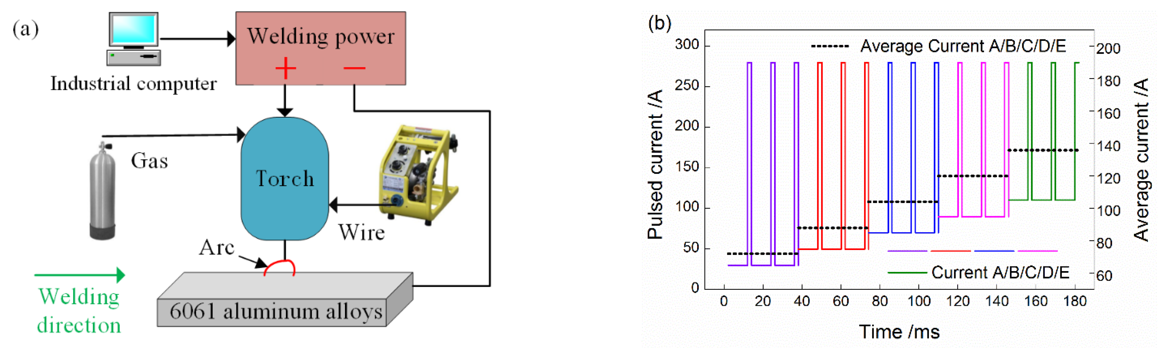
2. Materials and Methods

A bead-on-plate welding experiment was conducted on aluminum alloy AA6061 base metal (250 × 60 × 3 mm3) using ER4047 filler wire, and the experimental setup is displayed in Figure 1a. The respective compositions of each material used in this study are provided in Table 1. A pulsed GMAW with good stability was employed to obtain a different average current, which changes within a wide range by adjusting the base current, as displayed in Figure 1b [21,22], and the parameters for welding are presented in Table 2. Pure argon was coaxially supplied as a shielding gas at a flow rate of 18 L/min. The specimens were cut along the transverse cross sections of the welds, then ground and polished with colloidal silica, and subsequently, etched for 30 s using the standard Keller agent (95 mL H2O, 1 mL HCl, 1.5 mL HF, and 2.5 mL HNO3). The chemical composition was tested using energy dispersive X-ray spectroscopy (EDS) NOVA NANOSEM 430.
In order to verify the forming mechanism of wall constraints on the weld profile, different constraint conditions of the bottom wall were designed by applying supporting plates at different positions on the back of the base metal. In order to compare the influence on the weld profile with and without the supporting plate, a back supporting plate was placed in the middle of a weld bead; to compare the influence of the supporting plate on the arc crater of the molten pool, the supporting plate was placed at the tail of the weld; finally, to compare the influence of the side wall constraint on the weld profile, the supporting plate was applied on one side and both sides of the weld, respectively. The experimental schemes of four different supporting positions are shown in Figure 2.
The specimen size is given in Figure 2e. After welding, the tensile test was carried out on the Instron 8801 hydraulic tensile testing machine with a loading speed of 2 mm/min.

3. Results and Discussion

Our previous study [23] showed that when the heat input was at a low level of 122 J/mm, the upper surface of the weld was displayed as an inverted “U” shape (Figure 3a,b). As the heat input increased to 163 J/mm, the reinforcement of the three longitudinal sections along the welding direction of the weld gradually became prominent, namely, the reinforcement of the center plane and the reinforcement of both sides. From the cross section morphology, it can be seen that the upper surface has three high points, so it is shown as a “W” shape (Figure 3c,d); this shape not only occurred in the 3 mm aluminum plate but also in the experiment with the aluminum plate 2 mm thick.
When the heat input increased further to 204 J/mm, the weld reinforcement continued to decrease, different from the previous upper surface morphology of the weld in the W-shaped stage. When the heat input reached 204 J/mm, the reinforcement in the central plane with the maximum height decreased fastest. It could be found that the reinforcement in the central plane of the weld sunk and was lower than the reinforcement in the two sides. As the reinforcement existed only in the two sides, the upper surface contour of the weld presented a “V” shape (Figure 3e) due to its low middle plate and two high side plates. When the heat input was further increased to 231 J/mm, not only the reinforcement of the central plane was sunk but also the reinforcement of both sides. At this time, since the reinforcement of the three longitudinal sections along the welding direction was lower than the surface of the base metal, the upper surface of the weld was in a “U” shape (Figure 3f). According to the image and our samples, during our experiment the welded plate did not show obvious distortion. This may result from the not quite high heat input and the tightly fixed effect.
According to the above morphological characteristics of the upper surface of the weld, it can be seen that the upper surface of the weld experienced four stages of inverted U, W, V, and U shapes during the increase in heat input. The formation of these stages is not only related to the heat input of welding and the driving forces of the molten pool but also is affected by the solid–liquid state of the bottom wall. The bottom wall of the molten pool plays a role in supporting and restricting the molten metal and promoting it to change the flow direction. In these comprehensive effects, the heat input of the current is responsible for melting the base metal and forming the molten pool, while various driving forces acting on the molten pool drive the flow of the molten metal, and the flow channel is composed of the bottom wall and side wall of the molten pool. While these molten pool walls restrict the flow of the molten metal, the molten metal has a large amount of heat energy and impact kinetic energy. Therefore, the walls of the molten pool are constantly “thermally eroded” to further “excavate” the channel of the molten pool. Hence, the flow channel of molten metal is not only affected by its own thickness and other material characteristics but also affected by heating input and driving force of molten pool.

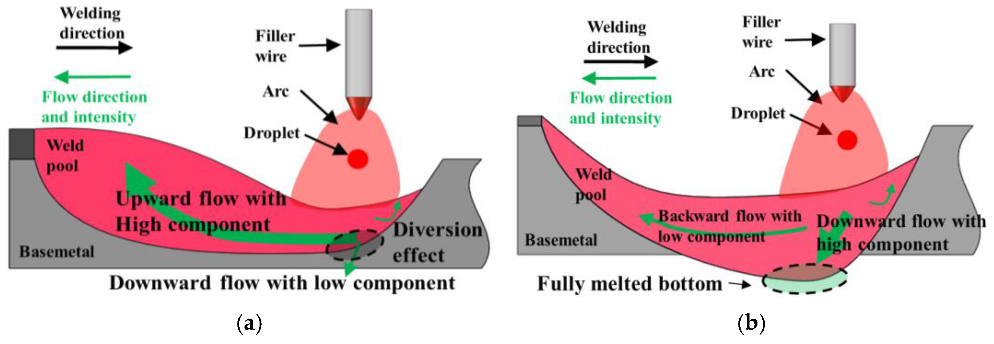
3.1. Effect of Driving Forces and Wall Constraint on the Flow Pattern of Molten Pool

The above-mentioned formation process of the upper surface morphology of the weld indicates that the weld reinforcement consists of three parts: the reinforcement of the central plane and the reinforcement of both sides, and its formation process is mainly affected by the welding heat input and the driving force of the weld pool. When the heat input is at a low level, the excess molten filler metal accumulates on the surface of the base metal, thus, covering the reinforcement on both sides due to the small capacity of the molten pool for the molten metal. With the increase in the heat input, the capacity of the molten pool to accommodate the filler metal increases, and the reinforcement on both sides gradually appears. At this time, the reinforcement on the central plane formed by the molten metal driven by the droplet impact is also clearly visible.
The forming mechanism is related to the droplet impact and the wall constraint provided by the bottom wall. When the penetration is not complete, the solid bottom wall of the molten pool has a greater constraint on the direction of the molten metal, as shown in Figure 4a. However, when the heat input increases further to 204 J/mm, due to the complete melting of the bottom wall, it no longer has a sufficiently effective restraining and redirecting effect on the fluid flow driven by the droplet impact, resulting in more molten metal flowing to the bottom wall of the molten pool and less molten metal flowing to the tail of the molten pool; thus, the reinforcement of the central plane disappears, as shown in Figure 4b. After the welding current is further increased, the reinforcement width on the back of the base metal is greater than that on the upper surface. Due to the lack of effective support, the reinforcement on both sides is also sunk below the base metal surface, therefore the U-shaped upper surface comes into being.
It can be seen from the above analysis that the shape of the upper surface of the molten pool is jointly determined by the droplet impact, which plays an active driving role, and the wall constraint, which plays a passive restraining role. When the base metal surface is not completely penetrated, the droplet impact promotes the molten metal to flow in the molten pool [24]. When it flows to the bottom wall of the molten pool, the solid bottom wall restricts a large amount of molten metal to flow backward, thus, forming an upper surface reinforcement in the central plane. When the base metal is completely penetrated, due to its loss of the constraint effect by the solid bottom wall, a large number of molten metal does not change the flow direction. It accumulates on the bottom wall of the molten pool to maintain and form a bottom wall reinforcement. Meanwhile, due to the lack of metal melt reflux, there is a depression on the upper surface. When the base metal is completely penetrated, the molten metal driven by the droplet flows to the bottom wall of the molten pool. Meanwhile there is a depression on the upper surface due to the lack of molten metal reflux. Therefore, from the point of weld formation, the role of the bottom wall is to divert or redistribute the molten metal in the molten pool: when the bottom wall is solid, due to its strong restraining and redirecting effect on the molten metal, more molten metal in the molten pool is divided to flow backwards and accumulate, forming a weld with high reinforcement.
With the continuous melting of the bottom wall, its ability to change the direction of the molten metal is weakened, resulting in less molten metal being divided into backward flows, thus the height of the weld upper surface reinforcement is continuously reduced; When the bottom wall is further melted, due to the loss of its restraining and redirecting effect from the bottom wall, more molten metal flows downwards and accumulates directly under the drive of droplet impact and other molten pool forces, and almost no molten metal refluxes to form the upper surface reinforcement, thus, forming a weld with prominent reinforcement on its back surface and concave on its upper surface, which is the “diversion” effect by the bottom wall on the molten metal.
Since the size of the weld upper surface reinforcement directly depends on the “diversion” effect of the bottom wall, and its size reflects the “diversion” effect of the bottom wall, therefore, the upper surface reinforcement forming coefficient Rc is taken as the measurement index of the diversion capacity of the bottom wall, and its calculation is shown as follows, where, R h is the height of the upper surface height, and R w is the width of the upper surface height.
R c = R h R w
Figure 5 shows the height, width, and forming coefficient of the weld reinforcement corresponding to different heat inputs. It can be seen from the figure that the height of reinforcement gradually decreases with the increase in heat input, while its width gradually increases. After calculation, the reinforcement forming coefficient gradually decreases from 0.30 to −0.09 with the increase in heat input. A negative number means the collapse of the upper surface reinforcement. Therefore, the reinforcement forming coefficient has the ability to reflect the diversion capacity of the bottom wall.

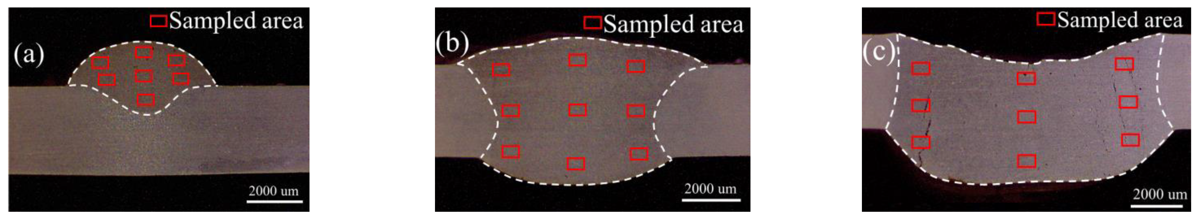
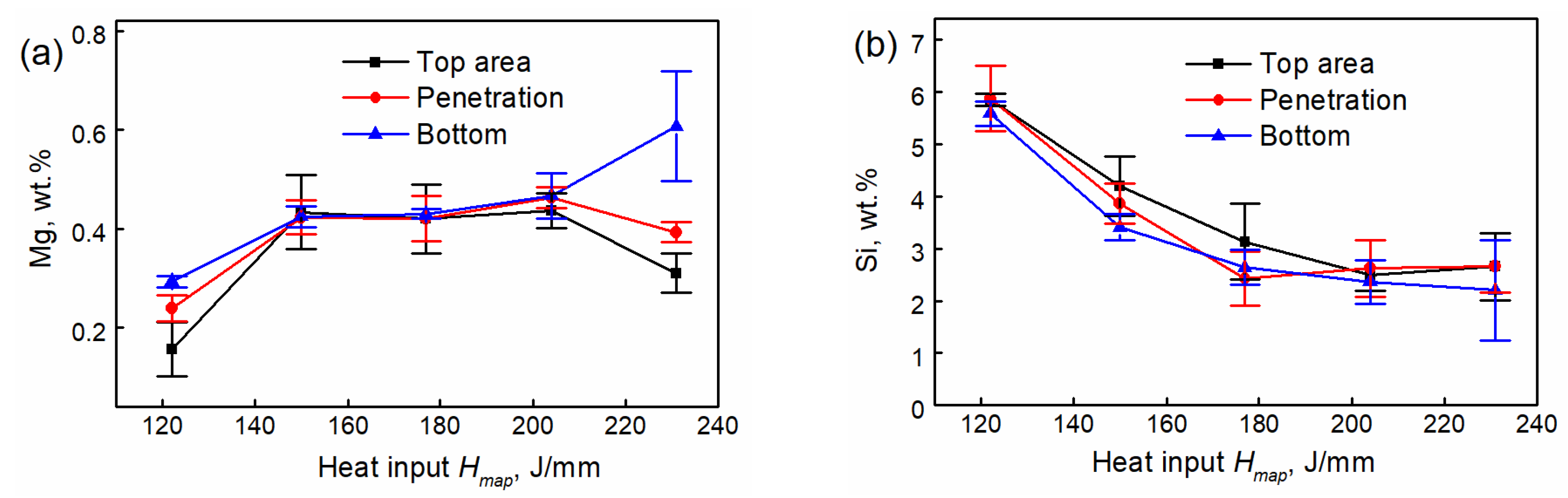
3.2. Distribution of Chemical Element

In order to study the influence of flow pattern in different forming stages on the distribution of weld composition, EDS chemical composition analysis was carried out on the top area, penetration, and weld bottom of the weld respectively. For the weld in different stages, the schematic diagram of the sampling areas is shown in Figure 6. At least three areas were collected in each region, and the three areas were located on the left, middle, and right. In order to avoid the influence of micro-segregation, the area of each sampling region was more than 10,000 um2 [25]. For the fully penetrated specimen, the bottom of the weld pool is actually the reinforcement at the back of the weld.
Meanwhile, the cracks can be seen in Figure 6c. This is because when the heat input increases to a high level, the bottom wall is fully penetrated, resulting in a lack of support for the molten metal. Therefore, the molten metal flows downward without adequate support by the bottom wall, and when there is not enough molten metal flowing downward, the crack happens.
With the increase in heat input, as shown in Figure 7b–d, when the weld enters into the stage of the fusion width matching with the reinforcement, there is no obvious difference in the content of Mg and Si in each area of the weld, showing good uniformity. This is because at this stage, the droplet can not only impact the bottom of the weld pool, making the content of Si no obvious difference in the depth direction of the weld, but also the droplet impact can drive the molten metal at the bottom to move backward and then upward, thus, the base metal component “tracker” Mg element can be more evenly distributed in each area of the weld, especially in the up area.
With the further increase in heat input, the weld enters the stage of the upper surface depression. It can be seen from Figure 7e that although the “tracker” of the filler wire by the Si element still shows no obvious difference in each area of the weld, the content of the Mg element as the “tracker” of base metal, however, shows once again that the content varies along the depth. In the centerplate of the weld pool, the content of the Mg element at the bottom of weld is 0.61 wt.%, while the content of the Mg element decreases to 0.39 wt.%, 0.31 wt.%, respectively, with the increase in weld height, which means the content of the Mg element at the bottom of weld is about 196.77% of that in the top area.
The result shows that even though the molten drops can still impact the bottom of the molten pool, the role of restriction and redirection undertaken by the bottom wall disappears greatly because the bottom wall of the molten pool completely melted with the increase in heat input and the driving forces, thus, resulting in less molten metal flowing backward and upward. Therefore, when the heat input reaches a high level, more base metal compositions accumulate at the bottom of the molten pool, while less flows to the middle and upper parts of the molten pool with the loss of the restriction and redirection role of the bottom wall. Therefore, with the increase in heat input, the content of the Mg element becomes less in the corresponding areas.
Figure 8a,b show the changes in the Mg and Si content with heat input in each area of the weld, respectively. The average values of each area are calculated after being collected from the left, right, and middle parts. It can be seen from the two figures that the content of the Mg element gradually increases with the increase in heat input, and the content of the Si element decreases with the increase in heat input. This is because with the increase in heat input, the melting amount of the base metal increases faster than that of the filler wire. Especially when the heat input is less than 150 J/mm, with the increase in melting amount of base metal, the content of the Si element in the weld area increases, At the same time, because the base metal melting speed is faster than that of the filler wire, the content of the Si element gradually decreases. When the heat input enters into the width–height matching stage, the content of each element becomes steady. When the heat input is further increased until the base metal bottom wall is completely melted, the content of Si in each zone is significantly different again due to the change in flow pattern in the molten pool. Meanwhile, according to Moshtaghi [26], the higher heat input leads to lower fraction in its microstructure.

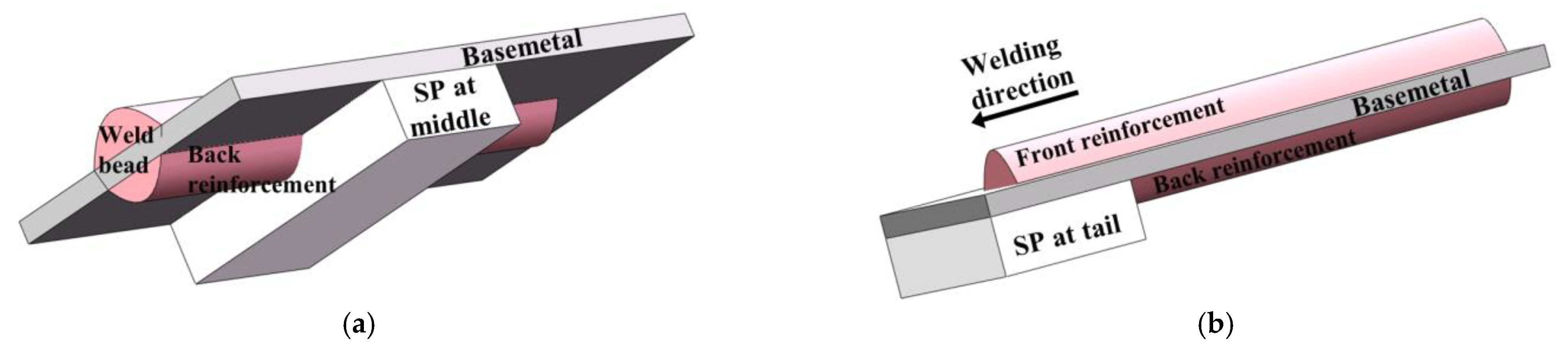
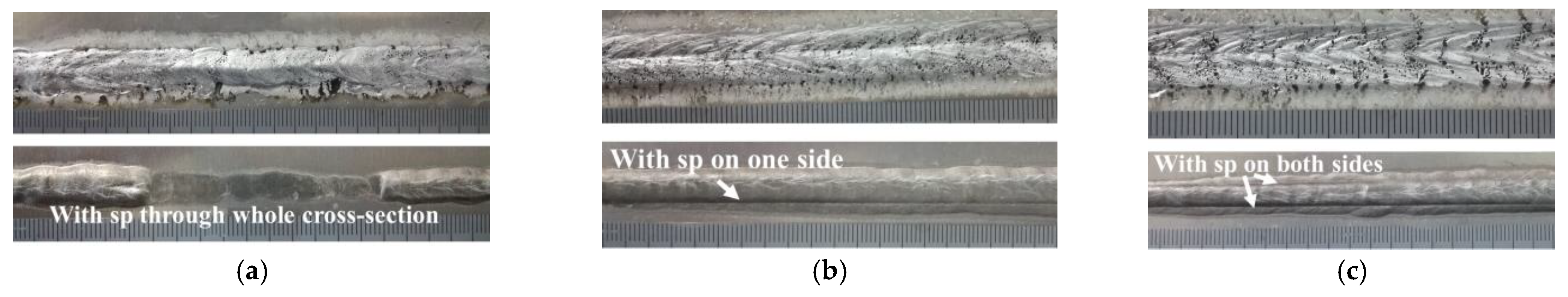
3.3. Profile with Different Supporting Plates

The weld appearances with different supporting plates are shown in Figure 9. Figure 9a shows the B70 weld appearance with the supporting plate at the middle position, and Figure 9b,c show, respectively, the B110 weld appearance under different unilateral supports and bilateral supporting plates. It can be seen from Figure 9a that when the back supporting plate is added, the front reinforcement of the weld increases, and the back reinforcement disappears due to the role of the supporting plate. In Figure 9b,c, the “dividing line” left on the back of the weld due to the effect of the supporting plate can be obviously seen. The three cases illustrate the constraint effect of the supporting plate on the weld formation.
In order to better understand this constraint effect, Figure 10 shows the weld profile with different supporting cases; Figure 10a,d show the comparison of B70 cross-section before and after the presence of mid-section supporting plate; Figure 10b,c,e,f show the weld profiles of B110 sample when there is no single side and double side supporting plate, respectively, and the white arrows in the figure show the position of the supporting plates. It can be seen from Figure 10a,d that when there is no supporting plate at the back of a weld, the reinforcement at the back is larger, while it is smaller at the front. When the back supporting plate is added, the reinforcement at the back decreases and the reinforcement at the front increases rapidly. The data comparison between the two cases is shown in Figure 11.

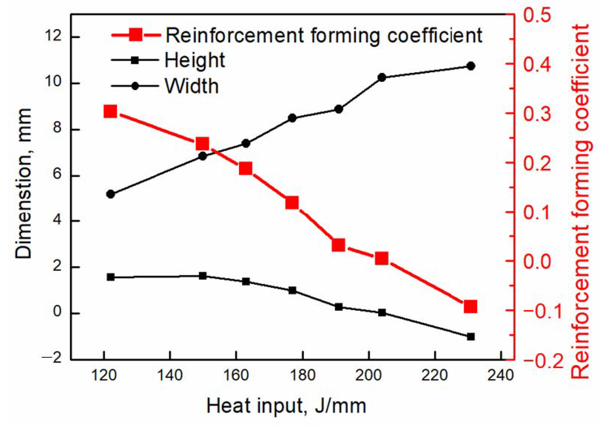
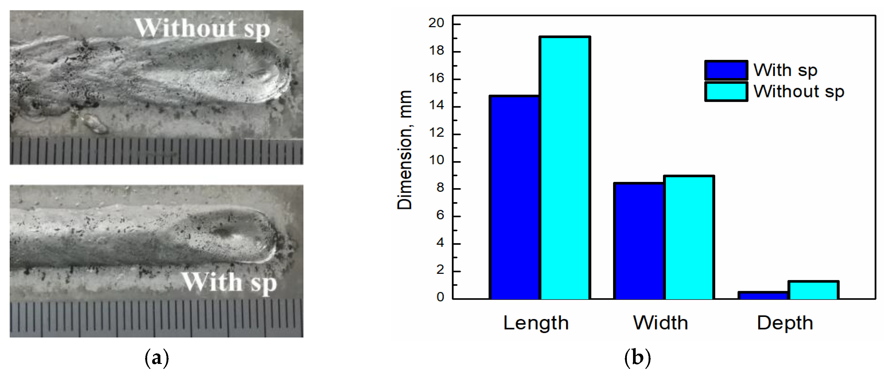
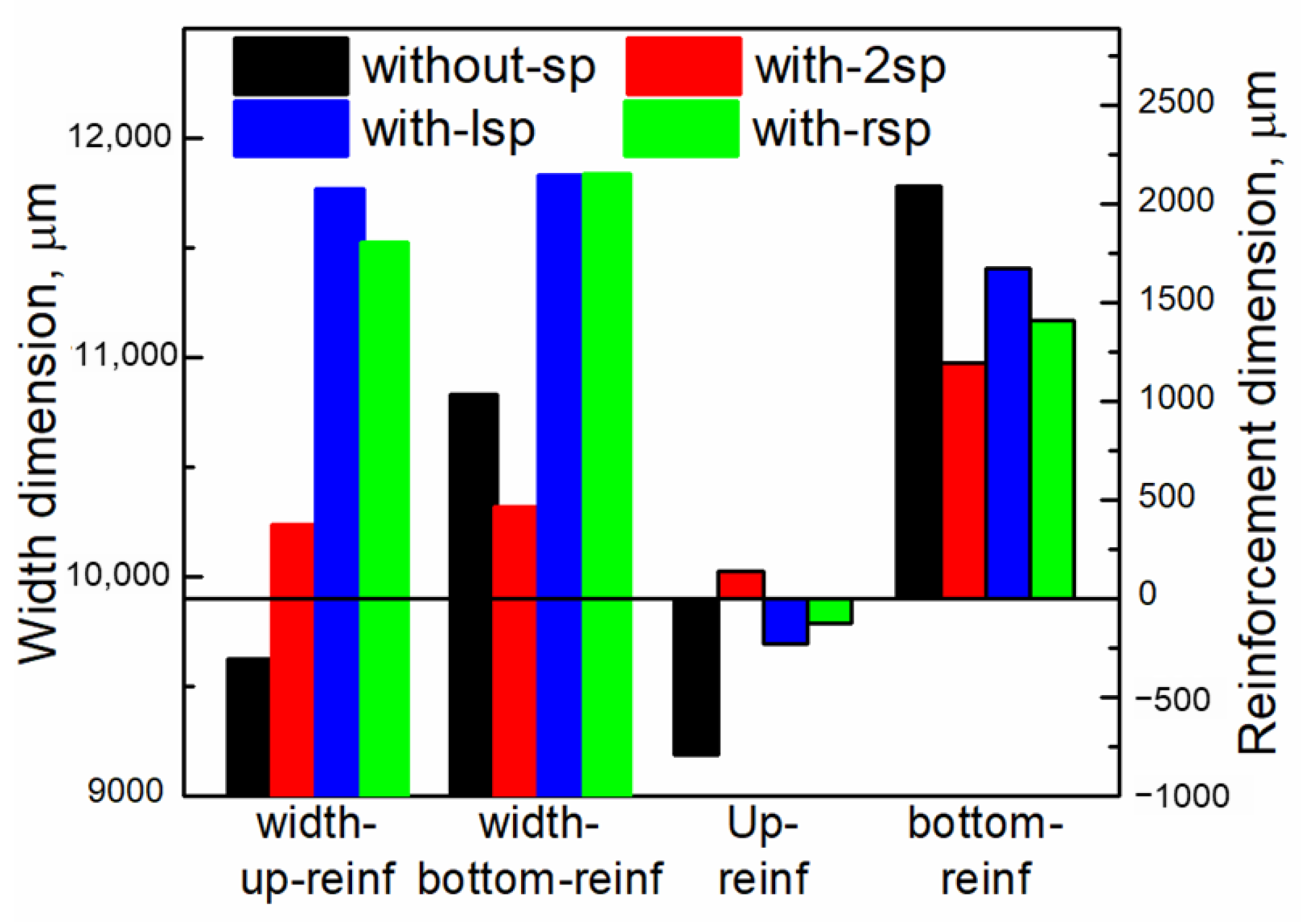
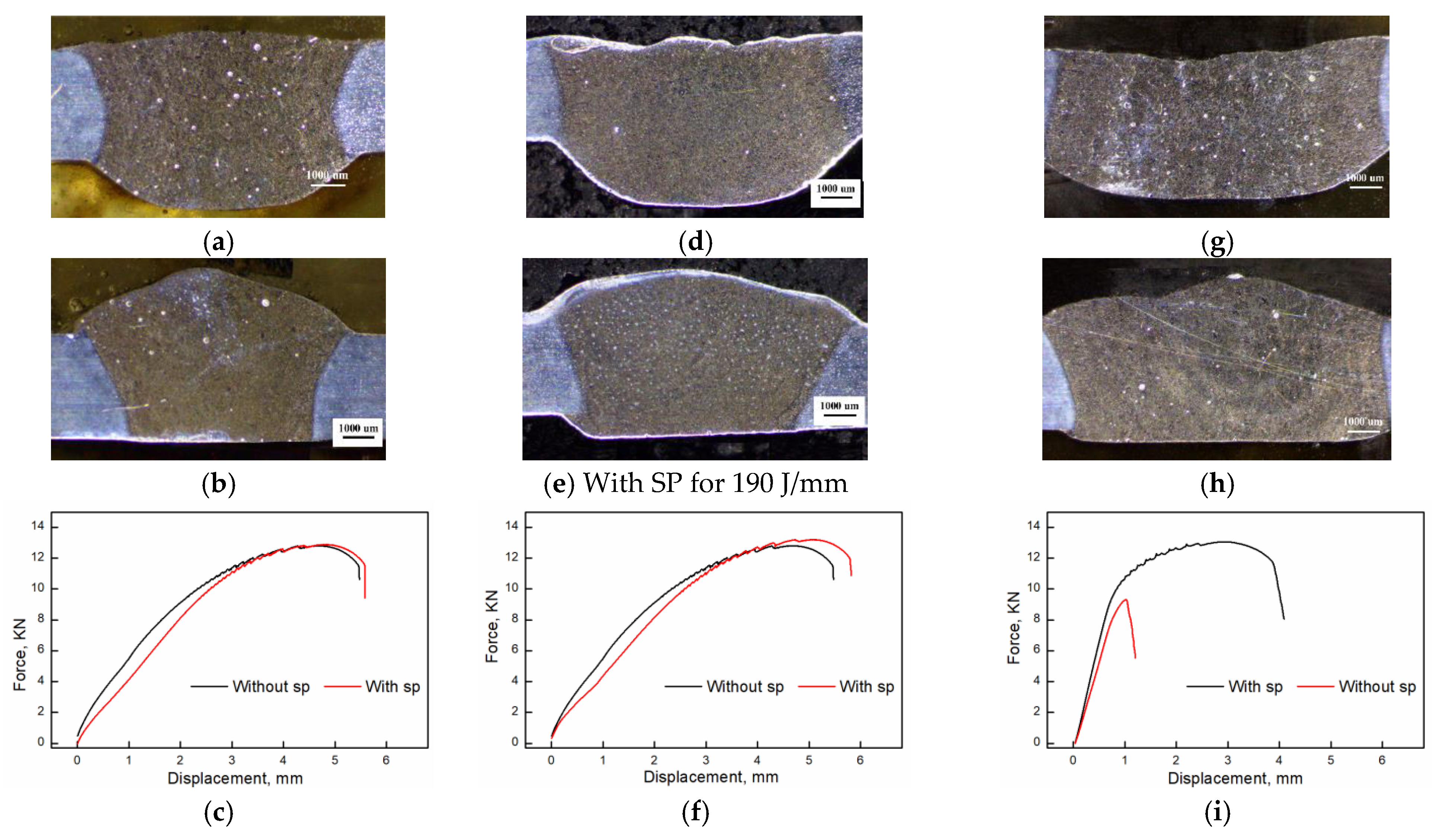
3.4. Comparison of Bead Dimensions with and without Supporting Plate

Figure 11 shows the comparison of weld cross-sectional dimensions of a B70 weld with and without supporting plates. It can be seen from this Figure 11 and Figure 10a,d that when there is a supporting plate at the back of the weld, the upper weld width (UP-with) is slightly smaller than that without a supporting plate (UP-without), but the bottom weld width (Bottom-with) reduced significantly from 7472 μm to 5312 μm. Meanwhile, the upper and bottom reinforcement of the weld shows a more significant difference. When there is a supporting plate, the upper reinforcement is 1901 μm. After removing the back supporting plate, the upper reinforcement is only 394 μm. Namely, the former is approximately 4.82 times the latter. The lower reinforcement is also very different in two cases. When there is a back supporting plate, the lower reinforcement is only 180 μm. When there is no back supporting plate, the lower reinforcement is 1458 μm. The former is only 12.35% of the latter. The change in reinforcement dimension also causes the corresponding change in contact angle, that is, when the back supporting plate is added, the upper contact angle increases and the lower contact angle decreases.
It can be seen from the above weld profiles and their sizes that the presence of the back supporting plate of the weld has a significant impact on the forming of a weld. For example, when there is a supporting plate, the reinforcement of the upper surface of the weld (B70 sample) increases by 3.82 times, while the fusion width of the upper surface decreases slightly from 8408 μm to 7810 μm by 7.11%. The reinforcement forming coefficient Rc increased sharply from 0.05 to 0.24 after the supporting plate was added, with an increase in 480%. The melting width of the lower surface, however, decreased by 40.66%. This is because with the addition of supporting plates at the back of the weld, the flow pattern in the weld pool has changed greatly. When the weld is fully penetrated and unsupported, the bottom cannot effectively restrict the molten metal to flow backwards due to the weak constraint of the bottom wall, resulting in a large part of the molten metal flowing downward under the driving force of droplet impact and other forces, thus, forming a large back reinforcement and a small front reinforcement on the upper surface. After the supporting plate constraint is applied to the back of the weld, as shown in Figure 12, the base metal state of the weld remains unchanged and its constraint on the metal melt in the weld pool is still weak. However, due to the role of the back supporting plate, when the fluid driven by the droplet impact flows to the bottom wall of the weld pool, it can no longer drive the molten metal to flow downward under the combined effect of the cooling effect of the supporting plate on the bottom wall and the new constraint provided by the supporting plate. Namely, under the constraint of the supporting plate, the backward flow component is enhanced owing to the increased constraint and redirection effect rebuilt by the supporting plate. On the other hand, the downward flow component of molten metal is weakened owing to the enhanced bottom constraint effect. Therefore, the reinforcement on the upper surface is significantly increased by 3.82 times after the back supporting plate is applied, which directly shows how the profile of a weld is affected by the enhanced constraint role of a newly applied supporting plate.

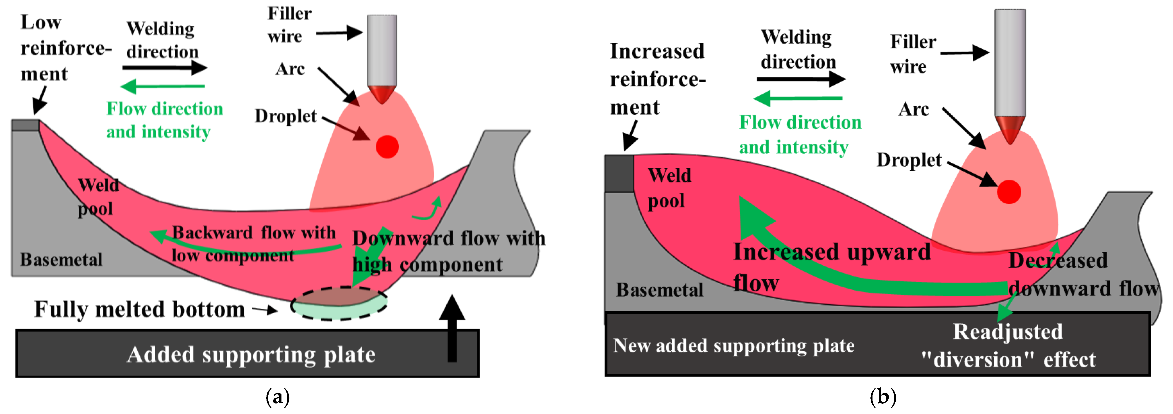
3.5. Formation Mechanism with Supporting Plate

This is also proven by the change in the crater shape and its size, as shown in Figure 13. Figure 13a shows the comparison of the crater shape with or without the supporting plate, and Figure 13b shows the dimension comparison of two craters. It can be seen from the two figures that when the back supporting plate is added, the length, width, and depth of the crater decrease, and the depth of the crater changes most significantly, from 1.27 mm to 0.49 mm, with a decrease of 159.18%. However, the length changes from 19.12 mm to 14.81 mm, with a decrease of 31.13%, and the depth also changes greatly. The width change in the crater is the smallest, with a decrease of only 0.53 mm, a decrease of 6.29%. The change in crater size indicates that when the back supporting plate is added, the metal in the molten pool can no longer flow downward due to the enhanced constraint of the bottom wall, so the backward and then upward reflow metal increases. Meanwhile, the arc pressure and other forces are basically unchanged. Therefore, when the reflow molten metal increases, the crater size decreases significantly.
Figure 14 shows the dimension comparison of the weld cross-section of the B110 sample under different supporting conditions. It can be seen from this figure and Figure 10 that when the back supporting condition differs, the weld profile and size are significantly different. When there is no back supporting plate, the upper weld width is 9615 μm, and the lower weld width is 10,824 μm. However, when two side supporting plates are added at the back, the upper and lower weld widths are 10,233 μm and 10,310 μm, respectively. Namely, the difference between the two weld widths is significantly reduced. Compared with the case without the supporting plate, the upper weld width is significantly increased, and the lower weld width is evidently reduced. This is because the supply of the back supporting plate changes the flow pattern of the molten metal in the weld pool, forcing more molten metal to flow backward and then upward, thus, lifting the position of the center of the heat source to melt more base metal in the upper area. Therefore, the upper weld width is increased, and the size of the lower weld width decreases. It is the wall constraint provided by the back supporting plate that makes more molten metal flow backward. Meanwhile, when constraints are applied on both sides of the weld, the depression of the upper reinforcement disappears owing to the accumulation of refluxed molten metal. Meanwhile, the size of the back reinforcement decreases due to the lack of downward flow of molten metal. At the same time, it can be seen from Figure 10c,f that for unilateral support, the fusion line on the support side is shown as a “horn” shape, while the fusion line on the non-support side is the “dumbbell” shape. This is because the molten metal on the support side cannot continue to flow downward, so it continuously accumulates here and brings a lot of heat, which causes more base metal to melt on this side, thus, it shows a “horn” shape. Moreover, due to more melting of the base metal on this side, the weld width is significantly larger than that without the back supporting plate. In summation, the constraint and diversion effect of the bottom wall on the weld pool flow pattern and on the weld formation are demonstrated by the conditions with or without back supporting plate.
In order to verify the effect of the wall constraint on the mechanical properties of weld joints, tensile tests of samples with and without supporting plates were carried out on B70, B80, and B90 samples, respectively. The cross-section comparison and tensile results are shown in Figure 15 and Table 3. It can be seen from the figure that for the weld with a collapsed upper surface, the tensile property increases, but the degree of increase varies for different welds. For the well-formed B70 sample, as shown in Figure 15a–c, the increase in the tensile property can be almost ignored. For the B80 sample with a slight depression on the upper surface, its tensile property is slightly increased from 12.80 KN to 13.21 KN, as shown in Figure 15d–f. For the B90 sample with serious surface depression, its tensile property was significantly improved from 9.31 KN to 13.02 KN, with an increase of 39.85%, as shown in Figure 15g–i. Meanwhile, it can be seen from Figure 16 that the fracture surface shows both the dimples (Zone A in Figure 16a,b) and cleavage faces (Zone B in Figure 16a,c), which means the fracture is a complex effect of ductile and brittle fracture.
Meanwhile, it can be seen from the fracture position (Figure 15j,k) that the fracture position is transferred from the weld bead to the heat affected zone. This is because under the wall constraint provided by the back supporting plate, the molten metal in the molten pool regains the ability to flow backwards to form a well-formed weld with no collapse on the upper surface reinforcement in the weld bead zone, thus, increasing the effective penetration of the weld. Therefore the fracture position is transferred to the heat affected zone.
Figure 17 displays the microhardness of samples welded with all levels of heat input. As we can see, the width of the weld is increased with the heat input increasing; the maximum hardness of the samples is measured at 79 HV for the weld bead with heat input of 150 J/mm. For the weld bead with a heat input of 231 J/mm, the excessive heat input makes the microstructure coarser, and the cracks increase, which results in the lower microhardness.

4. Conclusions

In this paper, the mechanism of the influence of the weld pool wall constraint on weld profile formation in GMAW was discussed. The main conclusions are as follows:
(1)
The flow pattern of molten metal and the weld profile are significantly affected by the wall constraint of the bottom wall. When the molten pool is not fully penetrated, most of the molten metal flows to the rear of the molten pool to form weld reinforcement. As the bottom wall changes to being completely penetrated because of the increase in heat input, the constraint effect of the bottom wall on the molten metal gradually weakens, resulting in the decrease or even collapse of the front reinforcement. It shows that the wall constraint has a “diversion” effect on the molten metal. Therefore, the reinforcement forming coefficient Rc is proposed to value the diversion ability.
(2)
The distribution of composition is also affected by the flow pattern and wall constraint. When the bottom is fully melted, the content of the Mg element, namely, the “tracker” of the base metal, varies obviously along the depth of the weld zone.
(3)
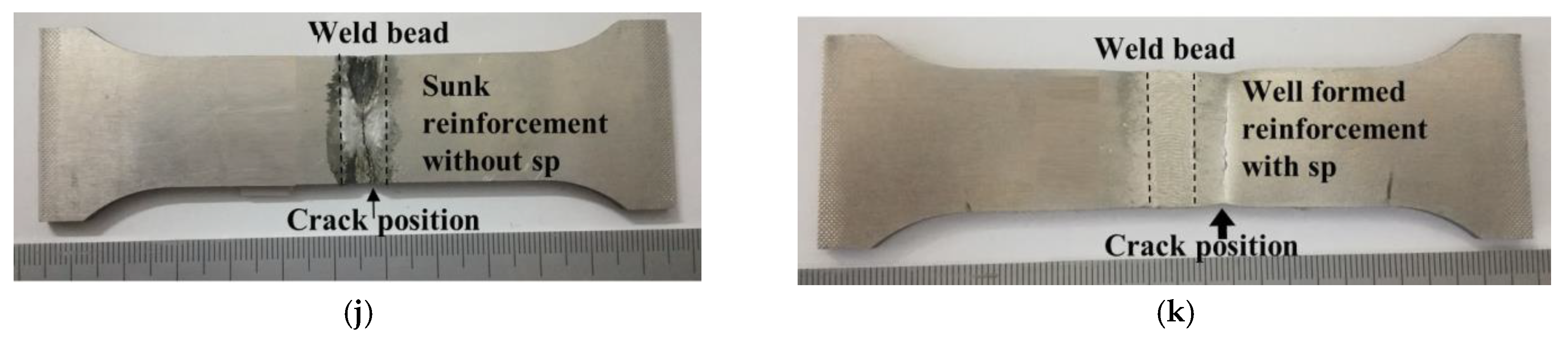
For the fully penetrated weld, the supporting plate on the back of the weld has a significant impact on the weld profile forming. This is because the supporting plate re-establishes the wall constraint on the flow of molten metal in the weld pool, thus restricting the molten metal to flow back and up again. The tensile property can be significantly improved by using wall constraint, such as the tensile strength of the weld increasing by 39.85% after adding back supporting plate.

Author Contributions

Conceptualization, Z.Z. and L.H.; methodology, G.L. and Z.Z.; validation, G.L. and Z.Z.; formal analysis, Q.J.; writing—original draft preparation, Z.Z.; writing—review and editing, L.H.; project administration, L.H.; funding acquisition, Z.Z. All authors have read and agreed to the published version of the manuscript.

Funding

This research was funded by Guangdong Basic and Applied Basic Research Foundation (2019A1515110627), Project of Educational Commission of Guangdong Province of China (2021KTSCX262), Guangzhou Panyu Polytechnic Technology Research (2021KJ22) and Guangxi Science and Technology Base and Talent Project Research Fund (Grant No. Guike AD21220002).

Institutional Review Board Statement

Not applicable.

Informed Consent Statement

Not applicable.

Data Availability Statement

The data presented in this study are available on request from the corresponding author. The data are not publicly available due to privacy restrictions.

Conflicts of Interest

The authors declare no conflict of interest.

References

  1. Nguyen, T.C.; Weckman, D.C.; Johnson, D.A.; Kerr, H.W. The humping phenomenon during high speed gas metal arc welding. Sci. Technol. Weld. Join. 2005, 10, 447–459. [Google Scholar] [CrossRef]
  2. Chuansong, H.Z.W. Experimental investigation on forming process of humping bead in high speedmag arc welding. Acta Metall. Sin. 2008, 44, 1445–1449. [Google Scholar]
  3. Chen, J.; Wu, C. Numerical simulation of forming process of humping bead in high speed gmaw. Acta Metall. Sin. 2009, 79, 1274–1280. [Google Scholar]
  4. Meng, X.; Qin, G.; Zou, Z. Investigation of humping defect in high speed gas tungsten arc welding by numerical modelling. Mater. Des. 2016, 94, 69–78. [Google Scholar] [CrossRef]
  5. Wu, D.; Hua, X.; Ye, D.; Zhang, J. Numerical analysis of humping formation in high speed GMAW process. Trans. Sin. Weld. Inst. 2016, 37, 5–8. [Google Scholar]
  6. Xu, G.; Cao, Q.; Hu, Q.; Zhang, W.; Liu, P.; Du, B. Modelling of bead hump formation in high speed gas metal arc welding. Sci. Technol. Weld. Join. 2016, 21, 700–710. [Google Scholar] [CrossRef]
  7. Cheon, J.; Kiran, D.V.; Na, S.J. Cfd based visualization of the finger shaped evolution in the gas metal arc welding process. Int. J. Heat Mass Transf. 2016, 97, 1–14. [Google Scholar] [CrossRef]
  8. Cho, D.W.; Song, W.H.; Cho, M.H.; Na, S.J. Analysis of submerged arc welding process by three-dimensional computational fluid dynamics simulations. J. Mater. Process. Technol. 2013, 213, 2278–2291. [Google Scholar] [CrossRef]
  9. Zong, R.; Chen, J.; Wu, C.S.; Padhy, G.K. Influence of molten metal flow on undercutting formation in gmaw. Sci. Technol. Weld. Join. 2016, 22, 198–207. [Google Scholar] [CrossRef]
  10. Chen, J.; Schwenk, C.; Wu, C.S.; Rethmeier, M. Predicting the influence of groove angle on heat transfer and fluid flow for new gas metal arc welding processes. Int. J. Heat Mass Transf. 2012, 55, 102–111. [Google Scholar] [CrossRef]
  11. Hu, J.; Tsai, H.L. Modelling of transport phenomena in 3d gmaw of thick metals with v groove. J. Phys. D Appl. Phys. 2008, 41, 065202. [Google Scholar] [CrossRef]
  12. Cho, D.-W.; Na, S.-J. Molten pool behaviors for second pass v-groove gmaw. Int. J. Heat Mass Transf. 2015, 88, 945–956. [Google Scholar] [CrossRef]
  13. Tomashchuk, I.; Sallamand, P.; Méasson, A.; Cicala, E.; Duband, M.; Peyre, P. Aluminum to titanium laser welding-brazing in v-shaped groove. J. Mater. Process. Technol. 2017, 245, 24–36. [Google Scholar] [CrossRef]
  14. Liu, L.; Shi, J.; Wang, H. Research on the Low Power Laser Induced Arc Hybrid Welding of Titanium Alloy Thinsheet. J. Mech. Eng. 2016, 52, 38–50 + 50. [Google Scholar] [CrossRef]
  15. Chai, X.; Yang, Y.K.; Carlson, B.E.; Kou, S. Gas metal arc welding of magnesium alloys: Oxide films, high crowns, and fingers. Weld. J. 2015, 94, 16S–33S. [Google Scholar]
  16. Liu, Z.; Fang, Y.; Qiu, J.; Feng, M.; Luo, Z.; Yuan, J. Stabilization of weld pool through jet flow argon gas backing in c-mn steel keyhole tig welding. J. Mater. Process. Technol. 2017, 250, 132–143. [Google Scholar] [CrossRef]
  17. Cho, D.W.; Na, S.J.; Cho, M.H.; Lee, J.S. A study on v-groove gmaw for various welding positions. J. Mater. Process. Technol. 2013, 213, 1640–1652. [Google Scholar] [CrossRef]
  18. Ebrahimi, A.; Babu, A.; Kleijn, C.R.; Hermans, M.J.M.; Richardson, I.M. The effect of groove shape on molten metal flow behaviour in gas metal arc welding. Materials 2021, 14, 7444. [Google Scholar] [CrossRef]
  19. Ni, M.; Qin, X.; Hu, Z.; Ji, F.; Yang, S.; Wang, S. Forming characteristics and control method of weld bead for gmaw on curved surface. Int. J. Adv. Manuf. Technol. 2022, 119, 1883–1908. [Google Scholar] [CrossRef]
  20. Han, S.; Liu, G.; Tang, X.; Xu, L.; Cui, H.; Shao, C. Effect of molten pool behaviors on welding defects in tandem ng-gmaw based on cfd simulation. Int. J. Heat Mass Transf. 2022, 195, 123165. [Google Scholar] [CrossRef]
  21. Zhu, Q.; Xue, J.; Yao, P.; Dong, C.; Wang, L.; Heng, G.; Li, Z. Gaussian pulsed current waveform welding for aluminum alloys. Mater. Manuf. Processes 2014, 30, 1124–1130. [Google Scholar] [CrossRef]
  22. Wang, L.; Jin, L.; Huang, W.; Xu, M.; Xue, J. Effect of thermal frequency on aa6061 aluminum alloy double pulsed gas metal arc welding. Mater. Manuf. Processes 2015, 31, 2152–2157. [Google Scholar] [CrossRef]
  23. Zhang, Z.; Xue, J. Profile map of weld beads and its formation mechanism in gas metal arc welding. Metals 2019, 9, 146. [Google Scholar] [CrossRef] [Green Version]
  24. Zhang, Z.; Xue, J.; Jin, L.; Wu, W. Effect of droplet impingement on the weld profile and grain morphology in the welding of aluminum alloys. Appl. Sci. 2018, 8, 1203. [Google Scholar] [CrossRef]
  25. Zhang, Z.; Huang, X.; Yao, P.; Xue, J. A new method for weld dilution calculation through chemical composition analysis. Metals 2021, 11, 131. [Google Scholar] [CrossRef]
  26. Moshtaghi, M.; Loder, B.; Safyari, M.; Willidal, T.; Hojo, T.; Mori, G. Hydrogen trapping and desorption affected by ferrite grain boundary types in shielded metal and flux-cored arc weldments with ni addition. Int. J. Hydrog. Energy 2022, 47, 20676–20683. [Google Scholar] [CrossRef]
Figure 1. Schematic of (a) experimental setup and (b) the adjustment of average current.
Coatings 12 01479 g001
Figure 2. Welding with different supporting plates. (a) SP at middle; (b) SP at tail; (c) SP at one side; (d) SP at both sides; (e) Dimensions of tensile specimens.
Coatings 12 01479 g002aCoatings 12 01479 g002b
Figure 3. The profile shape of a bead with the increase in heat input. (a) Inverted “U” shape; (b) Inverted “U” shape; (c) “W” shape; (d) “W” shape; (e) “V” shape; (f) “U” shape.
Coatings 12 01479 g003
Figure 4. Schematic diagram of fluid flow in weld pool with (a) solid bottom wall and (b) molten bottom wall.
Coatings 12 01479 g004
Figure 5. Coefficient of bead reinforcement with heat input.
Coatings 12 01479 g005
Figure 6. Sampled areas for typical weld profiles [25]. Heat input of (a) 122 J/mm; (b)177 J/mm; (c) 231 J/mm.
Coatings 12 01479 g006
Figure 7. Concentrations of compositions Mg, Si in different weld zones. Heat input of (a) 122 J/mm; (b) 150 J/mm; (c) 177 J/mm; (d) 204 J/mm; (e) 231 J/mm.
Coatings 12 01479 g007
Figure 8. Concentration change in composition for (a) Mg and (b) Si with heat inputs for different zones.
Coatings 12 01479 g008
Figure 9. Appearance of beads with different supporting plates on (a) whole cross-section; (b) one side; (c) both sides.
Coatings 12 01479 g009
Figure 10. Profile of beads with different underlying supporting plate: (a) no supporting plate for 177 J/mm; (b) with supporting plate for 177 J/mm; (c) no supporting plate for 231 J/mm; (d) with supporting plate on the left for 231 J/mm; (e) with supporting plate on the right for 231 J/mm; (f) with supporting plate on both sides for 231 J/mm.
Coatings 12 01479 g010aCoatings 12 01479 g010b
Figure 11. Comparison of bead dimensions with and without supporting plate.
Coatings 12 01479 g011
Figure 12. Comparison of flow pattern. (a) without supporting plate; (b) with supporting plate.
Coatings 12 01479 g012
Figure 13. Comparison of crater with and without supporting plates. (a) profile; (b) dimension.
Coatings 12 01479 g013
Figure 14. Comparison of cross-section dimension for different supporting cases.
Coatings 12 01479 g014
Figure 15. Comparison of tensile results with and without supporting plate. (a) Without SP for 177 J/mm; (b) With SP for 177 J/mm; (c) Tensile property for 177 J/mm; (d) Without SP for 190 J/mm; (e) With SP for 190 J/mm; (f) Tensile property for 190 J/mm; (g) Without SP for 204 J/mm; (h) With SP for 204 J/mm; (i) Tensile property for 204 J/mm; (j) Crack position without SP for 204 J/mm; (k) Crack position with SP for 204 J/mm.
Coatings 12 01479 g015aCoatings 12 01479 g015b
Figure 16. SEM image of the fracture surface for 204 J/mm with SP. (a) SEM image of the fracture surface; (b) Dimples on fracture surface; (c) Cleavage faces.
Coatings 12 01479 g016
Figure 17. Microhardness of the samples with various heat input.
Coatings 12 01479 g017
Table 1. Chemical compositions of AA6061 and ER4047 (wt.%).
MaterialMgSiFeCuMnCrTiAl
AA60610.870.660.420.290.090.270.08Bal.
ER40470.0511.060.300.130.120.040.07Bal.
Table 2. Welding process parameters for P-GMAW.
Process ParametersValue
Mean voltage (V)24.3
Mean current (A)A: 72 B: 88 C: 104 D: 120 E: 136
Base current (A)A: B30 B: B50 C: B70 D: B90 E: B110
Welding speed (mm/s)10
Heat input (J/mm)A: 122 B: 150 C: 177 D: 204 E: 231
Table 3. Tensile Test Results.
SampleYield Strength (MPa)Tensile Strength (MPa)ElongationFracture Location
B90-with sp125 ± 6175 ± 94.84Base metal
B90-without sp/125 ± 6/Weld bead
B80-with sp116 ± 4169 ± 54.74Base metal
B80-without sp130 ± 7179 ± 114.62Base metal
B70-with sp124 ± 8173 ± 65.24Base metal
B70-without sp122 ± 6172 ± 74.71Base metal
Publisher’s Note: MDPI stays neutral with regard to jurisdictional claims in published maps and institutional affiliations.

