Abstract
New digital technologies are improving the accuracy of orthognathic surgery. One of the new approaches transfers the surgical plan into real surgery without using an occlusal splint. This pilot study aims to validate the splintless approach to orthognathic surgery on a series of cases. Five patients were enrolled. Surgeries were planned using a digital surgical simulation method thanks to three-dimensional images. The splintless surgical approach was planned for maxillary reposition. This consisted of cutting guides and three-dimensionally (3D) printed custom titanium plates. These two were created using the computer-aided design and computer-aided manufacturing (CAD-CAM) technique and were used intraoperatively to guide the osteotomy and repositioning of the bony segments without the use of the surgical splint. The difference between the planned surgery and the real final position was analyzed thanks to superimposition techniques and landmark analysis. Statistical tests were performed to detect significant differences. No difference was found in any of the landmarks. Midline landmarks differed from the planned position by 0.34 mm. Higher variability was found in the posterior landmark. These findings suggest that a splintless approach is useful in transferring the surgical plan without using an occlusal splint.
1. Introduction
Diagnosis and planning of orthognathic surgery treatments are essential for obtaining aesthetic and functional results. Initially, the diagnosis was conducted on the plaster model and two-dimensional images. Treatment planning was performed via model surgery. Information to the laboratory was transferred with the facial bow. Then, during surgery, laboratory fabricated intermediate splints were used. A malposition up to 5 mm is reported by Ellis and coworkers [1]. Low accuracy in using face-bow is reported by Zizelmann and coworker [2]. The intermediate splints guide the position of the maxilla using the occlusion and the mandibular position. The planned result may not be achieved due to the condylar position and mandibular autorotation.
Nowadays, three-dimensional images are widely used for diagnosis and treatment planning. Surgery can be simulated on the three-dimensional images and intermediate splints can be produced thanks to the computer-aided design and manufacturing (CAD/CAM) technique. These new techniques are improving the accuracy of the treatment [3]. Nonetheless, the position of the maxilla still depends on the mandibular position and condylar rotation. The preoperative position of the mandible can differ from the intra-operative one due to its movability under general anesthesia. Errors can also be introduced during the acquisition of the preoperative records.
Another problem is the vertical displacement of the maxilla. Vertical dimension is usually measured using intraoral and extraoral reference points [4]. This is highly correlated with surgeon expertise. A novel solution to these problems is to transfer the three-dimensional plan using customized fixation miniplates [5]. With this procedure repositioning of the maxilla and mandible can be done without intermediate splints [6]. The procedure uses custom bone-supported guides for placed custom, highly rigid, miniplates produced using CAD-CAM technology. The high rigidity of the miniplates is another source of stability for this system [7].
Several authors have proposed a slightly different approach to this technique and many cases have been published [5,7,8,9,10,11,12,13,14,15,16,17,18,19,20]. Some criticalities of this technique are the mismatch between the planned position and the postoperative ones that some authors have reported [8,20] and the costs of the CAD/CAM individual splints and cutting guides [5,12]. The vast majority of the publications are single case reports. This pilot study aims to investigate the feasibility and the accuracy of a splintless approach to orthognathic surgery on a series of cases. Specifically, we expected that the difference between planned and the postoperative was aligned with the existing literature, cut off set ±2 mm for translational measurements [8].
2. Materials and Methods
2.1. Participants
This retrospective pilot study included five patients: three females and two males (mean age: 23 years ± 2 years), with dentofacial dysmorphism, belonging to the orthodontic department of the university hospital of Brescia.
The inclusion criteria were: (1) age greater than 20 years; (2) patients who were diagnosed with dentofacial dysmorphism; (3) clinical indication for corrective intervention of maxillomandibular dysmorphism; (4) good compliance and motivation for proposed orthodontic and surgical therapeutic procedure; (5) acquisition of informed consent for the study protocol.
Exclusion criteria were: (1) recurrence of dental-skeletal malocclusion following a previous surgery to correct dysmorphism of the same type (Le Fort I); (2) previous reduction and synthesis of fractures affecting the maxillary and mandibular bones; (3) diagnosis of craniofacial abnormalities; (4) systemic contraindications to major surgery.
Before the intervention, an assessment interview was administrated to patients to define objectives and explore patients’ expectations.
2.2. Preoperative Preparation
Patients underwent a preoperative cone-beam computed tomography. CBCT (Newtom 5G, QR, Verona, Italy) acquisitions were standardized as shown in Table 1.

Table 1.
Standard setting of CBCT.
The digital dental models were generated by scanning a set of stone dental models (Figure 1) using a 3D scanner (R1000, 3Shape, Copenhagen, Denmark). It was necessary to obtain a separate scan of the dental arches to remedy the poor resolution of the dental elements at the CBCT.
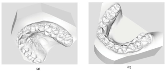
Figure 1.
Scanning of stone dental models: (a) upper jaw; (b) lower jaw.
The CBCT data were imported into planning software (version 3.0, ProPlan, Materialise NV, Leuven, Belgium) to generate 3D maxillary and mandibular models. The digital dental models were superimposed into the 3D skull model, replacing the less-than-accurate CT teeth. This resulted in a computerized composite skull model with an accurate rendition of both the bony structures and the teeth (Figure 2).
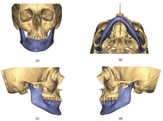
Figure 2.
3D maxillary and mandibular models: (a) front view; (b) bottom view; (c) right-side view; (d) left-side view.
According to the surgeon’s instructions, the maxillary osteotomies (Le Fort I) and Mandibular (Hunsuck-Epker) lines were then performed on the three-dimensional facial mass. The maxilla-mandibular complex was subsequently moved in the three spatial directions until the desired final position was obtained (Figure 3).
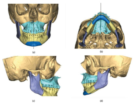
Figure 3.
3D maxillary and mandibular models in the final position: (a) front view; (b) bottom view; (c) right-side view; (d) left-side view.
Implantable devices were made using 3D software (version 16.0.1, 3-Matic, Materialise NV, Leuven, Belgium) on the three-dimensional model with jaws in the final position. The cutting guide for the upper jaw was made of Titanium 61-4V, with precise and stable support with at least one positioning hole per side, an angled guide to guide the inclination of the osteotomy line. This was to ensure that the guides could be anchored intraoperatively at the same locations as planned with maximum stability (Figure 4).
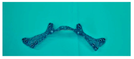
Figure 4.
Cutting guide for the upper jaw.
The osteosynthesis plate for the upper jaw was made of Titanium 61-4V and had a single structure for the connection of the elements of the two emulates (Figure 5).
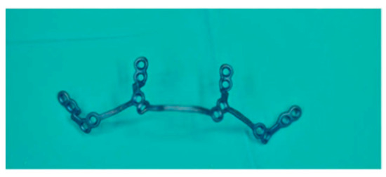
Figure 5.
Osteosynthesis plate for the upper jaw.
Finally, an occlusal plate was designed for mandibular repositioning. The construction of the devices took place with the CAM technique, using the 3D printer (Materialise, Leuven, Belgium) and laser sintering (Materialise, Leuven, Belgium) (Figure 6).
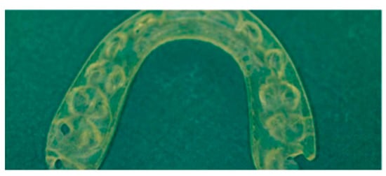
Figure 6.
Occlusal plate.
2.3. Surgical Procedure
Le Fort I osteotomy and bimaxillary surgery were performed under general anesthesia. After the bone surface of the maxilla was exposed, the cutting guides were mounted in the proper position and fixed with microscrews (Matrix-ORTHOGNATHIC, DePuy Synthes CMF, Oberdorf, Switzerland) (Figure 7).
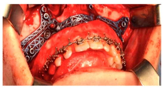
Figure 7.
The cutting guides in position.
Execution was by sagittal saw (Aesculap, Center Valley, PA, USA) or piezoelectric instrument (Mectron, Carasco, Italy) of the anterior portion of the osteotomy in the Le Fort I plane identified by the cutting guide (Figure 8).
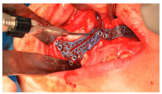
Figure 8.
The osteotomy in the Le Fort I plane identified by the cutting guide.
For the fixation of the next osteosynthesis plate, the planned hole positions were pre-drilled. Then, the osteotomy was performed of Le Fort I identified by the cutting template and after the usual procedure of down-fracture, bone interferences were removed until the four pre-bent plates fitted properly onto the maxilla. Using the drill holes as a guide, the plates were positioned and fixed with commercially available 1.85 mm osteosynthesis titanium screws (Matrix-ORTHOGNATHIC, DePuy Synthes CMF, Oberdorf, Switzerland) (Figure 9).
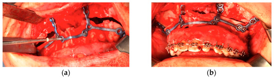
Figure 9.
The plates positioned with osteosynthesis titanium screws. (a) during the positioning, (b) is in position.
2.4. Analysis
Postoperative CT images were taken at 4 days post-surgery. The check of the accuracy of the virtual surgical programming was carried out using the Geomagic Qualify software (version 12.0). To do this, the virtual project was exported to an STL file and the control CBCTs were exported in the same format. These files were loaded into the software, which made it possible to superimpose the two images and, subsequently, analyze specific points to evaluate the differences between the two.
Once the files were imported, the symmetry planes were defined: the sagittal plane was identified with a line passing through nasion, point A, and basion, while the Frankfurt plane was taken as the reference for the axial plane. The sagittal plane is taken as the dominant plane and is aligned with the YZ plane in order to correctly orient the patient in space; as regards the axial plane, however, it has been aligned to the XY plane. In order to locate eight points, on which to make our measurements in a repeatable manner on the surface of the upper jaw, planes parallel to those indicated above have been built. In detail, there are two planes parallel to the sagittal, passing through the infra-orbital foramina and two planes parallel to the axial, passing respectively through point A and through the most concave point of the maxillo-zygomatic pillar. From the intersection of these four planes and between the sagittal plane and the maxilla surface, six points have been identified. The remaining two points considered were identified at the SNP (posterior nasal spine) and the incisor midpoint (midpoint between the central incisors) (Figure 10).

Figure 10.
Eight-point grid.
A superimposition was made between the STL planning and postoperative STL through a computerized recording on the stable bones of the skull and orbit. Finally, for each patient, the previously described points were taken into consideration and the discrepancy between virtual project and postoperative control was assessed. Two different methodologies were used to carry out this evaluation: color code mask and linear measurements. The color code mask allows a global evaluation of the discrepancies between the two objects; this function registers differences in a range between −2 and +2 mm, assigning a specific color for each value. For major discrepancies, gray color is automatically assigned. The linear measurements were performed with a specific function (selection measurement) of the Geomagic Qualify software, which allows the evaluation of the distances between the surfaces at the eight identified points. If the distance is positive, the real surface is in front of the planned one. A sign test was performed to assess if the median distance was 0 (H0: median of the sample is 0). Alpha was set at 0.05.
3. Results
The maximum deviation between these regions is 0.1 mm. This difference indicates the high reliability of the superimposition method. Figure 11 shows the difference between the planned and executed surgery in all the defined landmarks. Descriptive statistics are reported in Table 2.
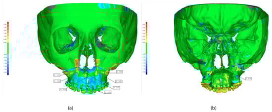
Figure 11.
Superimposition of pre surgery and post-surgery. STL: (a) front view, (b) back view.
Table 2.
Descriptive statistics of difference in landmark position between planned and executed surgery.
The results of the sign test (with null hypothesis median = 0), are reported in Table 3. The null hypothesis can never be rejected.
Table 3.
p-score of the sign test.
The measurements from the eight points identified as described above vary from patient to patient (Table 4). The margin of error between planning and postoperative is in the range of −1.17 mm to +1.48 mm, values considered acceptable in the considered literature.
Table 4.
Difference (mm) measured on five patients between planning and postoperative. PT, patient.
4. Discussion
Our study aimed to validate a splintless approach based on 3D planning in orthognathic surgery on five patients. To execute that, we planned the surgery using a digital surgical simulation method thanks to three-dimensional images. The splintless surgical approach was planned for maxillary reposition. This consisted of cutting guides and three-dimensionally (3D) printed custom titanium plates. These two were created using a computer-aided design and computer-aided manufacturing (CAD-CAM) technique and were used intraoperatively to guide the osteotomy and repositioning of the bony segments without the use of the surgical splint.
Traditionally, in orthognathic surgery, maxillary repositioning is mostly intraoperative based on surgical splints placed on intra- or extra-oral measurements. The splints are typically constructed manually through surgical models that lead to many sources of potential errors and unsatisfactory outcomes with maxillary mispositioning as great as 5 mm [1]. Despite this inaccuracy, this method is still widely used.
Nowadays, advances in planning software for 3D orthognathic surgery and the incorporation of data from CT or CBCT scans open up new horizons for diagnosis and treatment in orthognathic surgery. In this study, we aim to validate a splintless approach based on 3D planning in orthognathic surgery on a series of cases. Our results showed that splintless surgery is a very promising approach for maxillary repositioning with a very low range of error between preoperative planning and postoperative (around −1.17 mm/−1.48 mm). The translational differences (<2 mm) in accuracy assessment protocol was considered to be clinically insignificant [21,22]. The explanation could be due to the advantages related to the use of 3D planning. Compared to traditional assessment, 3D diagnosis and planning provide additional information related to the morphology of the bone at the planned osteotomy sites, the width of the tooth-bearing portion of the bone, and the location of the dental roots. This additional information makes maxillary repositioning safer and more reliable as well as allows better preparation in the case of anatomical variations, i.e., an atypical nerve position. Furthermore, the 3D planning overcomes the common problem related to the thickness of the anterior maxillary wall that might jeopardize screw stability, clearly indicating the location of thin bone to avoid [23].
The 3D image has been acquired using CBCT. This scan considerably reduces radiation dose, scanning time, and cost compared to CT [24,25]. However, despite these advantages, CBCT is not able to develop accurate images of the dental surfaces due to the presence of metal artifacts (braces) on patients’ teeth [26]. To overcome this issue, in our study, a scan of dental elements was introduced and superimposed on the 3D models deriving from the CBCT scans of the facial bones [23,27]. Regarding the cutting guides, a previous study [20] used two different guides, one for each side, with a further intervention to check the position using image-guided navigation. However, image-guided navigation has been reported to be less accurate than CAD/CAM splints, with a mean deviation of 0.67 mm vertically, 0.37 mm anteroposteriorly, and 0.2 mm mediolaterally [3]. Furthermore, Mazzoni and colleagues [20] showed that 30% of the guides required small adjustments. The CAD/CAM cutting guides used in this study were made in one piece crossing the midline to guarantee maximum fitting and accurate positioning.
In the present study, the custom-made titanium plate was used to simultaneously position and fix the maxilla, reducing the operative time and producing more stable results through the use of a 3D custom-made plate. The surgical outcomes were evaluated by superimposing the postoperative CBCT to the virtual plan. Our results showed a midline deviation of 0.31 mm, according to a previous study [15,17] showing a midline deviation of 0.34 to 0.39. This finding confirms the high precision of the procedure and the potential replicability of this innovative technique. In conclusion, the development of splintless orthognathic surgery applied to the upper jaw provides encouraging results in terms of precision achieved in the repositioning of the skeletal bases of the jaw. Furthermore, the protocol developed leads to a significant reduction in operating times.
Finally, the use of STL images for planning and postoperative evaluation allows the storage of three-dimensional data able to create a database available for subsequent studies. Despite the small number of cases, justified by the novelty of the approach, the promising results demonstrate the applicability of our protocol both in the planning phase and in terms of evaluation of the surgical result. Authors should discuss the results and how they can be interpreted in perspective of previous studies and of the working hypotheses. The findings and their implications should be discussed in the broadest context possible. Future research directions may also be highlighted.
5. Limitations
The limitations of this procedure are mostly time and costs. In our experience, the time between surgical planning and arrival of individualized devices was about 4 to 5 weeks, almost twice as long as the standard technique. This is related to greater complexity in the design of the surgical devices and the technical time required to ship them. However, a prolongation of the time required to schedule the surgery is associated with a significant reduction in intraoperative time from about 180 min described in the literature [8] to about 150 min in our cases, with, in particular, a reduction to 45 min of the operative time devoted to osteotomy and maxillary fixation. Costs are currently higher than the standard technique. However, in our opinion, the increased predictability of the final result and the reduction in operative time more than compensate for the increased expense incurred. Finally, given the pilot study of the study, a limitation is related to the small sample size. Further study will be conducted with a larger and more representative sample.
6. Conclusions
The results of the study suggest that a splintless approach resulted in acceptable accuracy in transferring the surgical plan without using an occlusal splint. All the difference between the planned and realized surgery is not clinically significant. However, in light of the wide variation and limited case numbers, further studies are necessary to determine the efficiency in the approach in terms of costs, surgical precision, and occlusal stability.
Author Contributions
Conceptualization, R.Z.; methodology, R.Z.; formal analysis, D.D. and G.I.; data curation, I.B. and U.Z.; writing—original draft preparation, R.Z. and G.O.; writing—review and editing, C.T. and G.O.; visualization, R.Z. and U.Z.; supervision, S.B.; project administration, S.B. and U.Z. All authors have read and agreed to the published version of the manuscript.
Funding
This research received no external funding.
Institutional Review Board Statement
The study was conducted according to the guidelines of the Declaration of Helsinki. The protocol of this study was approved by the review board of the Dental School of the University of Brescia (protocol code SPSS1907, 15-04-2019).
Informed Consent Statement
Not applicable.
Data Availability Statement
Data are available from the corresponding author upon reasonable request.
Conflicts of Interest
The authors declare no conflict of interest.
References
- Ellis, E. Accuracy of Model Surgery: Evaluation of an Old Technique and Introduction of a New One. J. Oral Maxillofac. Surg. 1990, 48, 1161–1167. [Google Scholar] [CrossRef] [PubMed]
- Zizelmann, C.; Hammer, B.; Gellrich, N.C.; Schwestka-Polly, R.; Rana, M.; Bucher, P. An Evaluation of Face-Bow Transfer for the Planning of Orthognathic Surgery. J. Oral Maxillofac. Surg. 2012, 70, 1944–1950. [Google Scholar] [CrossRef]
- Zinser, M.J.; Mischkowski, R.A.; Sailer, H.F.; Zöller, J.E. Computer-Assisted Orthognathic Surgery: Feasibility Study Using Multiple CAD/CAM Surgical Splints. Oral Surg. Oral Med. Oral Pathol. Oral Radiol. 2012, 113, 673–687. [Google Scholar] [CrossRef] [PubMed]
- Sun, Y.; Luebbers, H.-T.; Agbaje, J.O.; Schepers, S.; Vrielinck, L.; Lambrichts, I.; Politis, C. Accuracy of Upper Jaw Positioning with Intermediate Splint Fabrication after Virtual Planning in Bimaxillary Orthognathic Surgery. J. Craniofac. Surg. 2013, 24, 1871–1876. [Google Scholar] [CrossRef] [PubMed]
- Pascal, E.; Majoufre, C.; Bondaz, M.; Courtemanche, A.; Berger, M.; Bouletreau, P. Current Status of Surgical Planning and Transfer Methods in Orthognathic Surgery. J. Stomatol. oral Maxillofac. Surg. 2018, 119, 245–248. [Google Scholar] [PubMed]
- Han, J.J.; Yang, H.J.; Hwang, S.J. Repositioning of the Maxillomandibular Complex Using Maxillary Template Adjusted Only by Maxillary Surface Configuration without an Intermediate Splint in Orthognathic Surgery. J. Craniofac. Surg. 2016, 27, 1550–1553. [Google Scholar] [CrossRef] [PubMed]
- Brunso, J.; Franco, M.; Constantinescu, T.; Barbier, L.; Santamaría, J.A.; Alvarez, J. Custom-Machined Miniplates and Bone-Supported Guides for Orthognathic Surgery: A New Surgical Procedure. J. Oral Maxillofac. Surg. 2016, 74, 1061-e1. [Google Scholar] [CrossRef] [PubMed]
- Schouman, T.; Rouch, P.; Imholz, B.; Fasel, J.; Courvoisier, D.; Scolozzi, P. Accuracy Evaluation of CAD/CAM Generated Splints in Orthognathic Surgery: A Cadaveric Study. Head Face Med. 2015, 11, 24. [Google Scholar] [CrossRef] [PubMed]
- Sharifi, A.; Jones, R.; Ayoub, A.; Moos, K.; Walker, F.; Khambay, B.; McHugh, S. How Accurate Is Model Planning for Orthognathic Surgery? Int. J. Oral Maxillofac. Surg. 2008, 37, 1089–1093. [Google Scholar] [CrossRef]
- Gateno, J.; Xia, J.; Teichgraeber, J.F.; Rosen, A.; Hultgren, B.; Vadnais, T. The Precision of Computer-Generated Surgical Splints. J. Oral Maxillofac. Surg. 2003, 61, 814–817. [Google Scholar] [CrossRef]
- Kwon, T.G.; Choi, J.W.; Kyung, H.M.; Park, H.S. Accuracy of Maxillary Repositioning in Two-Jaw Surgery with Conventional Articulator Model Surgery versus Virtual Model Surgery. Int. J. Oral Maxillofac. Surg. 2014, 43, 732–738. [Google Scholar] [CrossRef] [PubMed]
- Imai, H.; Fujita, K.; Yamashita, Y.; Yajima, Y.; Takasu, H.; Takeda, A.; Honda, K.; Iwai, T.; Mitsudo, K.; Ono, T.; et al. Accuracy of Mandible-Independent Maxillary Repositioning Using Pre-Bent Locking Plates: A Pilot Study. Int. J. Oral Maxillofac. Surg. 2019, 49, 901–907. [Google Scholar] [CrossRef] [PubMed]
- Gander, T.; Bredell, M.; Eliades, T.; Rücker, M.; Essig, H. Splintless Orthognathic Surgery: A Novel Technique Using Patient-Specific Implants (PSI). J. Cranio-Maxillofac. Surg. 2015, 43, 319–322. [Google Scholar] [CrossRef] [PubMed]
- Wellens, H.L.L.; Kuijpers-Jagtman, A.M. Connecting the New with the Old: Modifying the Combined Application of Procrustes Superimposition and Principal Component Analysis, to Allow for Comparison with Traditional Lateral Cephalometric Variables. Eur. J. Orthod. 2016, 38, 569–576. [Google Scholar] [CrossRef][Green Version]
- Heufelder, M.; Wilde, F.; Pietzka, S.; Mascha, F.; Winter, K.; Schramm, A.; Rana, M. Clinical Accuracy of Waferless Maxillary Positioning Using Customized Surgical Guides and Patient Specific Osteosynthesis in Bimaxillary Orthognathic Surgery. J. Cranio-Maxillofac. Surg. 2017, 45, 1578–1585. [Google Scholar] [CrossRef]
- Kraeima, J.; Jansma, J.; Schepers, R.H. Splintless Surgery: Does Patient-Specific CAD-CAM Osteosynthesis Improve Accuracy of Le Fort I Osteotomy? Br. J. Oral Maxillofac. Surg. 2016, 54, 1085–1089. [Google Scholar] [CrossRef]
- Li, B.; Shen, S.; Jiang, W.; Li, J.; Jiang, T.; Xia, J.J.; Shen, S.G.; Wang, X. A New Approach of Splint-Less Orthognathic Surgery Using a Personalized Orthognathic Surgical Guide System: A Preliminary Study. Int. J. Oral Maxillofac. Surg. 2017, 46, 1298–1305. [Google Scholar] [CrossRef]
- Chin, S.-J.; Wilde, F.; Neuhaus, M.; Schramm, A.; Gellrich, N.-C.; Rana, M. Accuracy of Virtual Surgical Planning of Orthognathic Surgery with Aid of CAD/CAM Fabricated Surgical Splint—A Novel 3D Analyzing Algorithm. J. Cranio-Maxillofac. Surg. 2017, 45, 1962–1970. [Google Scholar] [CrossRef]
- Suojanen, J.; Leikola, J.; Stoor, P. The Use of Patient-Specific Implants in Orthognathic Surgery: A Series of 32 Maxillary Osteotomy Patients. J. Cranio-Maxillofac. Surg. 2016, 44, 1913–1916. [Google Scholar] [CrossRef]
- Mazzoni, S.; Bianchi, A.; Schiariti, G.; Badiali, G.; Marchetti, C. Computer-Aided Design and Computer-Aided Manufacturing Cutting Guides and Customized Titanium Plates Are Useful in Upper Maxilla Waferless Repositioning. J. Oral Maxillofac. Surg. 2015, 73, 701–707. [Google Scholar] [CrossRef]
- Karanxha, L.; Rossi, D.; Hamanaka, R.; Giannì, A.B.; Baj, A.; Moon, W.; Del Fabbro, M.; Romano, M. Accuracy of splint vs splintless technique for virtually planned orthognathic surgery: A voxel-based three-dimensional analysis. J. Cranio-Maxillofac. Surg. 2021, 49, 1–8. [Google Scholar] [CrossRef] [PubMed]
- Chen, H.; Jiang, N.; Bi, R.; Liu, Y.; Li, Y.; Zhao, W.; Zhu, S. Comparison of the Accuracy of Maxillary Repositioning Between Using Splints and Templates in 2-Jaw Orthognathic Surgery. J. Oral Maxillofac. Surg. 2022, 80, 331–1339. [Google Scholar] [CrossRef] [PubMed]
- Hanafy, M.; Akoush, Y.; Abou-ElFetouh, A.; Mounir, R.M. Precision of Orthognathic Digital Plan Transfer Using Patient-Specific Cutting Guides and Osteosynthesis versus Mixed Analogue–Digitally Planned Surgery: A Randomized Controlled Clinical Trial. Int. J. Oral Maxillofac. Surg. 2020, 49, 62–68. [Google Scholar] [PubMed]
- Lin, H.-H.; Lo, L.-J. Three-Dimensional Computer-Assisted Surgical Simulation and Intraoperative Navigation in Orthognathic Surgery: A Literature Review. J. Formos. Med. Assoc. 2015, 114, 300–307. [Google Scholar] [CrossRef] [PubMed]
- Haas, O.L., Jr.; Becker, O.E.; De Oliveira, R.B. Computer-Aided Planning in Orthognathic Surgery—Systematic Review. Int. J. Oral Maxillofac. Surg. 2015, 44, 329–342. [Google Scholar]
- De Vos, W.; Casselman, J.; Swennen, G.R.J. Cone-Beam Computerized Tomography (CBCT) Imaging of the Oral and Maxillofacial Region: A Systematic Review of the Literature. Int. J. Oral Maxillofac. Surg. 2009, 38, 609–625. [Google Scholar] [CrossRef]
- Centenero, S.A.-H.; Hernández-Alfaro, F. 3D Planning in Orthognathic Surgery: CAD/CAM Surgical Splints and Prediction of the Soft and Hard Tissues Results–Our Experience in 16 Cases. J. Cranio-Maxillofac. Surg. 2012, 40, 162–168. [Google Scholar]
Publisher’s Note: MDPI stays neutral with regard to jurisdictional claims in published maps and institutional affiliations. |
© 2022 by the authors. Licensee MDPI, Basel, Switzerland. This article is an open access article distributed under the terms and conditions of the Creative Commons Attribution (CC BY) license (https://creativecommons.org/licenses/by/4.0/).