Review

Laser Cladding-Based Surface Modification of Carbon Steel and High-Alloy Steel for Extreme Condition Applications

by
Merbin John
1,
Udaya Bhat Kuruveri
2 and
Pradeep L. Menezes
1,*
1
Department of Mechanical Engineering, University of Nevada, Reno, NV 89557, USA
2
Department of Metallurgical and Materials Engineering, National Institute of Technology Karnataka, Surathkal 575025, India
*
Author to whom correspondence should be addressed.
Coatings 2022, 12(10), 1444; https://doi.org/10.3390/coatings12101444
Submission received: 12 September 2022 / Revised: 25 September 2022 / Accepted: 27 September 2022 / Published: 30 September 2022

Abstract

:
Laser cladding (LC) is a laser-based surface modification technique widely adopted to develop a thin coating or remanufacture worn-out mechanical components that work in extreme conditions. LC helps to generate superior surface properties and surface integrity on the substrate surface, improving the service life. This review paper provides a comprehensive overview of the LC process, different powder feeding methods, and the uniqueness of LC over other coating techniques. More specifically, the current state-of-the-art of the LC process on carbon steel and high-alloy steel-based mechanical components operating in diverse industries was elucidated. Furthermore, the effect of LC processes on mechanical properties such as wear, corrosion and fatigue properties are discussed. In addition, the LC process’s influence on microstructural features and microstructural modifications is explained. Finally, this study explores some potential applications of the LC process in diverse industries.

1. Introduction

Mechanical components working in an extreme environment require superior mechanical properties and surface integrity to perform their intended task without failure. Scholars reported premature failure of mechanical components when operating in extreme and challenging circumstances. The extreme conditions include high pressure, high temperature, and corrosive environments. They originate from the surface and propagate through the bulk of the component, affecting longevity and leading to severe financial hardships. Fatigue, corrosion, and wear account for over 80% of mechanical failures [1]. These failures depend on the surface microstructure and surface properties rather than bulk properties [2], hence it is always recommended to provide superior surface integrity and surface mechanical properties for mechanical components that operate in dynamic and challenging environments [3,4,5,6]. Tremendous research has been put forward to develop mechanical components that can provide superior surface integrity and surface mechanical properties. These research efforts lead to various surface modification techniques that can develop excellent surface properties and help the mechanical components to sustain for a long time without failure in challenging environmental conditions [7,8]. For enhanced wear and corrosion properties, scholars adopted various coating techniques. These surface modification methods include physical vapor deposition [9], chemical vapor deposition [10], thermal spray coatings [11], plasma spraying [12], cold spray deposition [13], nitriding [14], boriding [15], carbonitriding [16], carburizing [17] friction surfacing [18], laser surface alloying [19], and laser cladding (LC) [20]. Among the various coating methods developed, LC is considered a prominent surface modification technique capable of delivering excellent wear and corrosion properties to the substrate material [21]. This is primarily due to the extreme non-equilibrium processing conditions such as spontaneous heating, melting, and cooling when laser and coating material interact. LC is considered not only a process for manufacturing components but also for repairing parts being used under extreme conditions [22,23,24]. There is another closely related method, i.e., laser surface alloying. Here, the surface of the substrate is alloyed. The substrate surface is melted using a high-energy laser beam, and alloying metal is added to the molten pool [25,26,27]. The alloy addition mixes with the molten substrate, and on resolidification, the surface will be a new alloy, imparting desired properties to the surface.
LC is a laser-assisted process for coating the surface of the substrate. The coating helps to improve the substrate’s hardness and wear, heat, and corrosion resistance [28,29,30,31,32,33]. The process has high economic efficiency and produces high-performance coatings on the cheaper substrates without affecting the bulk properties of the substrate. It can reduce the cost of precious materials and reduce environmental pollution. Lasers used for cladding are predominantly CO2 lasers and solid-state lasers, such as disc lasers, fiber lasers, and diode lasers. Laser cladding is helpful in many industrial applications such as slurry transport systems, oil industries, hydroelectric power plants, coal slurry transportation systems, etc. [30,34,35,36].
This review paper comprehensively discusses the LC techniques for carbon and high-alloy steel. The LC process, the powder feeding methods, and the advantages of LC techniques compared to other coating deposition methods are discussed in Section 2. The effect of the LC process on mechanical properties and microstructural features and carbon steel and high-alloy steel is explained in Section 3 and Section 4. Finally, Section 5 discusses some industrial applications of the LC process.

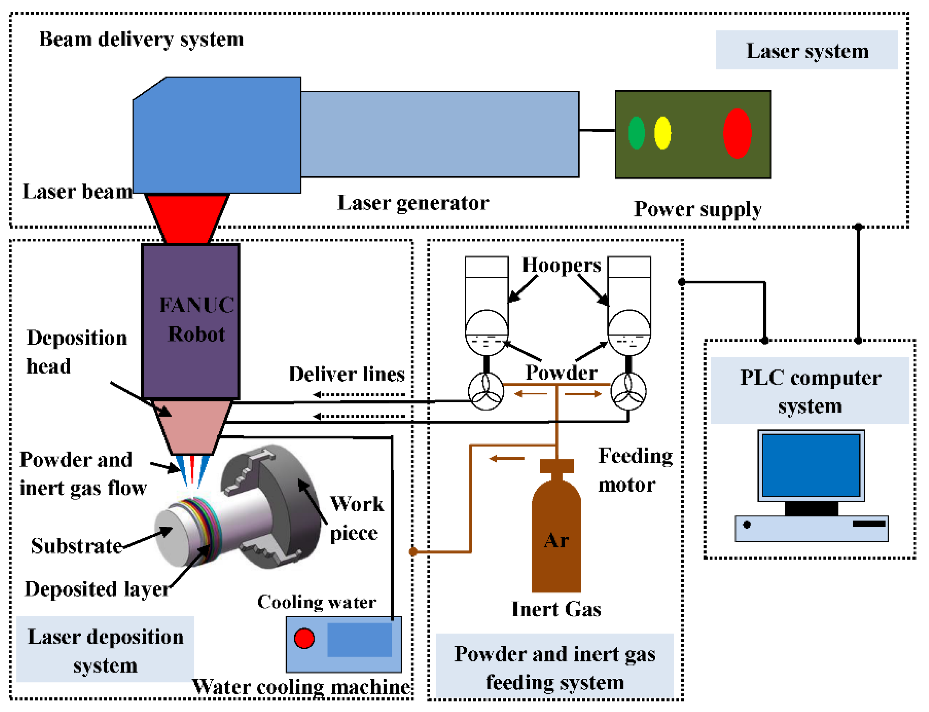
2. Laser Cladding Process

In the LC process, a high-intensity laser beam and coating material interact, and the beam melts the coating material along with a thin layer of the substrate material. The molten metal quickly resolidifies with excellent metallurgical bonding to the substrate. LC has many characteristics that are not observed in other coating technologies as a process. Some of the characteristics of LC are that it is a rapid solidification process, and various microstructures can be manipulated by controlling the LC process parameters. The schematics of the LC process are shown in Figure 1.
The process offers a very low dilution rate, and the coating thickness can be easily controlled in the range of 0.2 mm to 5.0 mm [37,38]. Compared to other processes, it employs smaller heat input; hence, distortion is minimal, and it can often be controlled within the tolerance limit required during the assembly of the part. It is an eco-friendly, robust, and flexible technique. During the LC process, the temperature gradient is large, which exclusively helps to develop a finer microstructure and ultimately provides superior surface properties [39]. Practically, it can deposit coatings from a wide range of powders, including deposition of high melting point alloys on low melting point substrates. With proper accessories, difficult-to-reach areas and components with complex geometries could be coated [40].
There are two methods by which the powders are fed into the cladding system. They are powder preset and synchronous powder feeding methods [41,42,43,44,45]. Amongst these methods, synchronous powder feeding has the benefits of the feasibility of automation and computer control, improved laser energy absorption, minimal porosity in the cladding volume, etc. It is also helpful for cladding ceramic materials on various metallic materials. Sometimes, instead of powder feeding, wire feeding is also employed. The synchronous powder feeding methods can be further classified into coaxial powder feeding, off-axis powder feeding, and wire feeding methods [46,47]. The preplaced and synchronous powder feeding methods are shown in Figure 2. A recent development in LC is using a higher scanning speed greater than 20 m/min. Here, the powder to be deposited is fed into the line of the focused beam. It ensures that the powders are already molten when they contact the substrate. It creates a shallow melt pool on the substrate, and when the laser beam is moved, the molten pool will be rapidly cooled, allowing it to solidify immediately. Reducing the amount of heat reaching the substrate minimizes the dilution level and heat effect on the substrate [48,49].
Different substrates could be subjected to LC. They are carbon steels of different types, alloy steels, non-ferrous metals such as aluminum alloys [50], copper alloys [51], magnesium alloys [52], and titanium alloys [53]. However, this article’s focus is limited to the LC of various steels. The main process parameters of LC are laser power, beam diameter, workpiece motion velocity, prepowder layer thickness, powder feed rate, nozzle angle, and standoff distance.
To obtain a superior clad layer with enhanced surface properties, proper selection of LC parameters is of utmost importance. Researchers have investigated LC to produce a uniform, homogeneous clad layer with an excellent metallurgical bond with the substrate, free of cracks and porosity [28]. The following is an excerpt on the development in laser cladding of different steels to improve surface hardness.

3. Laser Cladding of Carbon Steel

Several scholars performed LC of carbon steel that is used for diverse applications in various industries. Their studies revealed that LC is a superior surface modification process that can provide improved surface properties such as corrosion, wear, and hardness.

3.1. LC of 17-4 PH Stainless Steel on E355DD Steel Substrate

Nie et al. [23] explored LC of 17-4 PH stainless steel on E355DD substrate (a low alloy structural steel), focusing on improving wear, corrosion, and cavitation corrosion resistance. A powder of size 15 μm to 75 μm was used. The predried powder was fed through a coaxial powder injection system. The laser power ranged from 2000 W, 2200 W, to 2400 W. They observed that during cladding, the top part of the substrate was melted along with the powder, leading to dilution of the 17-4 PH cladding. The dilution rate was in the range of 9% to 13%. The dilution rate was increased with an increase in the laser power. The dilution rate plays a vital role in microstructure development and the performance of the coatings [54]. When the dilution rate is significant, a good metallurgical bond is obtained, but it has an adverse effect on the substrate and reduces the powder’s effective use. The issue of dilution during welding of clad materials and methods of foreseeing the solidification mode are predicted in [55,56]. By knowing these, an optimal dilution can be achieved.
On the contrary, when the dilution rate is low, it can lead to poor metallurgical bonding. Furthermore, the shape of the molten pool varies as a function of the laser power. At lower power, the shape was circular, and with increased power, it became elliptical. Rapid cooling of LC will cause the cladding layer to solidify before the gas is blown out of it. A few pores inside the cladding area were attributed to the evaporation of some of the alloying elements, as shown in Figure 3. Solidification microstructure depends on the temperature gradient (G) to the solidification rate (R). As the molten pool starts freezing, the molten pool irradiates heat to the matrix. Due to the high thermal conductivity, the preferential growth of the microstructure along the Z direction was observed. Increasing laser power leads to a lower cooling rate, producing a coarser microstructure. The coating had only a martensite (α′-Fe) phase. It is attributed to the domination of lath martensite transformation during rapid cooling in the solid-state. Most of the γ-Fe is transformed into α՛-Fe after cooling. It is valid for different laser powers since they all have similar power densities. When heat input is very low, the upper powder does not entirely melt, leading to defects such as lack of fusion. Lack of fusion will also lead to a lower dilution rate. When bonding between substrate and cladding layer is good, defects at the interface are fewer.
The heat-affected zone (HAZ) also showed lath martensite, which is attributed to heating to high temperatures and rapid cooling. Overall, three layers, namely substrate, HAZ, and cladding layer, were identified in the clad system. There was a clear demarcation in the microhardness values. Substrate hardness was 160 HV, the interface region had 420 HV, and the clad layer had 370 HV. Hardness increases due to Hall–Petch strengthening and transformation into the martensite phase. The hardness variation in the three specimens is shown in Figure 4. An increase in heat input and cooling time leads to coarser lath martensite in the HAZ, which causes a decrease in microhardness.

3.2. LC of Ni-Cr-Mo-W-xSi on 20 G Steel Substrate

Using a multi-track coaxial LC system, Liu et al. [57] deposited Ni-Cr-Mo-W-xSi on 20 G steel (a carbon structural steel). They investigated the effect of varying Si (0 wt.% to 5 wt.%) content on the phase constitution, microstructure evolution, and high-temperature sulfur corrosion resistance. They observed that the clad layer consists of Mo-rich and Cr-rich solid solutions. The optimized Si level in the clad layer was observed to be 1%. The corresponding composition promotes the enrichment of Mo and Cr in the inner layer, which forms a protective metal oxide scale. When the Si level is greater than 1%, cracks develop along the grain boundary, resulting in a drop in corrosion protection. Almeida et al. [58] deposited nickel and cobalt-based alloys on steel pipes used in the oil and gas industry. They noted the presence of a hard HAZ in the substrate during laser cladding. The coating and the HAZ had increased hardness. The LCed Stellite-6 and Inconel 625 coatings exhibited twice the hardness of the substrate. Increased hardness is expected to improve resistance to wear, but the microstructure changes at the HAZ are expected to be a concern in situations such as sulfide-assisted corrosion.

3.3. LC of Composites on Steel Substrate

Du et al. [59] deposited TiB2/Fe composite coating on AISI 1010 steel using LC. Results indicate that LC can make a good joint between the clad layer and the substrate. The clad layer consisted of TiB2 and α-Fe. The presence of TiB2 in the coating increased hardness considerably. They optimized the process parameters to obtain a defect-free coating. The coating had three distinct regions: clad layer, HAZ, and substrate. The hardness of the clad layer was >750 HV, whereas for the substrate it was approximately 170 HV. The HAZ had a gradient in hardness. The macrograph of the LC processed substrate is shown in Figure 5.
Li et al. [60] used a composite (Fe60 + WC) cladding on 16 Mn steel (Mn—1.2 to 1.6, C—0.1 to 0.2). WC particles of two sizes (small at 15–40 μm, large at 80–120 μm) were used in the composite cladding. The amount of added WC was fixed at 20%, and laser power—1.5 kW, scanning speed—240 mm/min, and powder feeding—10 g/min were used. Multiple tracks with 50% overlapping were used for coverage. The control sample was Fe60 cladding without WC particles. Two different kinds of WC particles were used: 15–40 μm (designated as WCs) and 80–120 μm (designated as WCl). Three coatings were considered. WCs, WCl, and a mix of WCs and WCl. The WC-free coating consisted of α-Fe, γ-(Fe, Ni), and (Cr, Fe)23C6. The main phases of small WC-reinforced coating are α-Fe, γ-(Fe, Ni), M23C6 (M is Fe or W), and WC. For large WC particles, there were two types of tungsten carbides, WC and W2C. In both cases, α-Fe was the matrix. In the case of WC-free coating, microstructure consisted of dendrites and interdendritic regions with lamellar structure. Dendrites had some amount of Cr along with the Fe. The interdendritic region was rich in Cr, Fe, and C. Lamellar structure was attributed to the eutectic reaction. In the case of WC-containing cladding, dendrites were much finer. The microstructure of dendrites in small WC particle cladding was very homogenous. The main phases were large dendrites and carbides occupying interdendritic space and white distributed particles (WCs). It was thought that WC nucleated first during cooling from high temperatures, and later carbides nucleated. The microstructure of large WC particle-reinforced coating was non-uniform. The microstructure had dendrites and fine lamellar eutectics in the interdendritic regions. The white WC particles were big and non-uniformly distributed. At the center, there were more. Microhardness was uniform in the clad zone in WC-free and small WC particle cladding. Hardness in small WC particle-based cladding was 940 HV which is 1.6 times that of WC-free cladding. Substrate hardness was nearly 200 HV, three times less than in WC-free cladding. The large WC particle clad layer had a hardness in the range of 570–610 HV. The authors also reported a significant reduction in wear rate and coefficient of friction of the substrate and cladded substrate. The WC-based coating exhibited the lowest coefficient of friction (COF) of 0.55 compared to other coatings and substrates. The wear resistance of the cladding material was increased by 71.5, 22.9, and 13.5 times, corresponding to the WCs, WCl, and mix of WCs and WCl cladding layer. Figure 6 demonstrates the COF and wear rate variation in the 16 Mn steel (Mn—1.2 to 1.6, C—0.1 to 0.2) and three clad layers on 16 Mn steel (Mn—1.2 to 1.6, C—0.1 to 0.2).

3.4. LC of Stellite on Steel Substrate

Gupta et al. [41] deposited a Stellite-6 layer on EN19 steel substrate using a CO2 laser. The Stellite-6 particle size ranged from 10 μm to 40 μm. The microstructure of the clad layer consisted of three layers: dendrites of Stellite-6, an alloyed region having an Fe and Co-presenting cellular microstructure, and the third was a heat-affected layer. The heat-affected layer had a mixture of martensite and pearlite. The microhardness of the clad layer reached a value close to 1200 HV, whereas the substrate hardness was 350 HV.
Wu et al. [45] explored high-speed LC of Stellite-6 on mild steel substrate. For this purpose, a Trumpf TruLaser with a coaxial LC system was used. The processing speed ranged from 10 m/min to 30 m/min. The powder feed focus position concerning the substrate top position was the variable. They noted that the focus position influences the size of the molten pool and, in turn, the clad layer thickness. They achieved a clad layer in the range of 190–250 μm. Further increase in the energy density (13 J/mm2 to 15 J/mm2) reduced the thickness due to evaporation of the clad particles, which was attributed to increased interaction between the beam and the particles. In general, the cross-section of the high-speed LC deposit has three layers—a clad layer, a laser-penetrated zone, and a HAZ. Laser energy density values influence the microstructure formation in the coating. At the lower energy range (7.68 J/mm2), the coating predominantly had columnar dendrites with small pockets of equiaxed dendrites. Further, reducing energy density to 5.12 J/mm2 increased the fraction of equiaxed dendrites, and the columnar dendrites were refined. The change in microstructural features was attributed to the higher cooling rate obtained with the smaller melt pool generated due to lower energy density. Furthermore, lower energy input means that less energy is transferred to the substrate, which reduces the size of the laser-penetrated zone. Researchers investigated the effect of such microstructure refinement on the microhardness variation. They noted that the microhardness in the coating produced with high-speed LC is much higher than that obtained using a conventional cladding [48,61]. Significant cracking was observed along the coarse columnar grain boundaries when Stellite-6 was cladded with higher laser energy (12.79 J/mm2). Table 1 indicates the observations of LC on low-carbon and high-alloy steel.

3.5. LC of Metallic Glasses on Steel Substrate

There are investigations exploring the feasibility of LC of metallic glasses on the surface of carbon steels. Basu et al. [29] studied the LC of amorphous coating/bulk metallic glass (BMG)-forming alloy, Fe-Cr-Mo-Y-N-C, on the AISI 4140 substrate. They used the powder preset method for adding cladding powder. Coating thickness was varied based on incident laser power and interaction time. They observed solute redistribution during laser processing, because of which crystalline phases nucleated. Even though the alloy is a BMG alloy, the clad layer had α-Fe, Fe7C3, Cr7C3, Fe2B, and YB12 crystallites. Relative values of these phases depend on the process parameters. One possible reason could be the lower cooling rate generated during cooling. Experimental support indicates that the lower cooling rate causes solute redistribution within the liquid pool and across the coating–substrate interface due to dissolution and interdiffusion. The coated layer has dendritic/cellular morphology with extremely fine and unresolved precipitates in the interdendritic spaces. The secondary arm spacing is in the range of 2.4–4.2 μm. They noted that increased power leads to coarser microstructures, as shown in Figure 7. Hardness measurements along the thickness direction presented a significant increase in the laser-clad region. It increased to 960 HV from the initial 240 HV. At the top, at a depth of 150 μm, hardness was high and then gradually reduced. An increase in hardness is attributed to the precipitation and dispersion of carbides, borides, and solute hardening. A gradual drop in hardness with an increase in depth is attributed to dilution and less precipitation. The gradual change in hardness is beneficial in the distribution of residual stress and fracture toughness. Additionally, it is expected to help in tribological behavior. Wang et al. [43] explored LC of (FeCrMoBC)98Nb2 amorphous alloy on 0.45% C steel substrate using a CO2-based coaxial powder feeding system.
The clad layer thickness was 1 mm. Their focus was on the effect of laser scanning speed on the clad layer’s macromorphology, microstructure, and microhardness. Various microstructures as a function of depth were observed. The substrate side showed plane crystal, cellular crystal, columnar crystal, equiaxed crystal, and amorphous layers. They noted that laser scanning speed affects the thickness of the amorphous layer. It also influences the dilution rate and cooling rate by altering the heat input. With the increase in speed, the coating had better hardness. It is attributed to fine grain strengthening, dispersion strengthening, and growth of the amorphous phase. The hardness of the amorphous phase was 1024 HV, whereas that of the crystalline phase was 706 HV. It indicates that the amorphous phase is responsible for higher hardness.
Wang et al. [31] deposited glass-forming alloy, namely FeCoCrMoCBY, onto the mild steel substrate by LC. They used a Nd:YAG pulse laser with energy density in the range of 97 J/mm2 to 128 J/mm2 to deposit coatings with a thickness of 0.2 mm to 0.5 mm. They varied the parameters such as pulse frequency, pulse energy, laser power, etc., to study the success of LC. They noted that with an increase in the laser power, the possibility of oxidation is greater. They observed that pulse energy and pulse frequency affect the macrostructure and microstructure of the clad layer.
During cladding using a pulsed laser beam, a molten pool will be formed during each pulse. Before the second pulse falls, it will be solidified. During the second pulse, another molten pool will be formed as a fresh pool. This step will be repeated to cover the entire area, and the coating will be made up of ripple patterns throughout the clad area. The frequency of pulsing decides the distance between the ripples. When the pulsing rate increases, the distance between the ripples will be reduced, the ripple pattern will become finer, and the pattern will disappear when the laser beam is continuous. Laser power has the opposite trend. If laser power exceeds a certain value, there will not be sufficient time for the molten pool to solidify entirely before the next pulse starts. So, the solidification of the first pulse is affected by the impingement of the second pulse. Now, the ripple pattern will become rougher. An increase in pulsing also has an effect in another way. As frequency increases, the number of pulses on a unit area increases, increasing the net input energy. This increases the pool’s energy, leading to increased penetration depth and increasing the extent of interaction between the clad material and the substrate. This will lead to metallurgical bonding. Sometimes, it will affect the solute dilution also. When the substrate and the clad layer have different thermal expansion behaviors, it will manifest in the generation of residual stresses. If the residual stress is tensile and exceeds the ultimate tensile strength, then cracks will be generated. Figure 8 shows cracks in clad layers.
Three zones, namely substrate, bonding, and cladding, were observed. Dendritic morphology is observed in the cladding zone. Increased laser power and pulsing frequency increase the width of the bonding zones. Authors have reported a bonding zone thickness ranging from 2 μm to 10 μm. The hardness of the substrate is 200 HV, that of the clad layer is 1000 HV (both layers). The maximum hardness observed is 1300 HV. High hardness in the clad region is attributed to the composite structure containing nanocrystals within the amorphous phase. Nanocrystals consisted of α-Fe, Fe3C, and Fe23C6 precipitated in the amorphous phase. The potentiodynamic polarization curves show low corrosion current and passive current with a passive region exceeding 1 V, demonstrating that the passive films on the clad layer are stable and possess excellent corrosion resistance (Figure 9).
The study on the feasibility of deposition of bulk metallic glass indicates that cladding can overcome the size limitation of BMGs since the size could not limit coatings. LC offers the benefits of higher power densities and results in high cooling rates (104–106 K/s), sufficient to make amorphous alloys. In addition, it creates a completely dense layer and a good metallurgical bond between the substrate and the coating layer. Furthermore, it can overcome geometry limitations. It can control the phase transformations and microstructure features to manipulate the final properties. It can offer the dual benefits of cladding and amorphous alloy to produce better coatings with higher hardness, wear resistance, corrosion resistance, and lower friction coefficient [29,31,43,71,72,73]. However, continued studies are essential to have an amorphous coating on the structural application, as retaining amorphous nature is always a challenge.
Lai et al. [22] reported the effects of cladding direction, preheating, and post heat treatment on microstructural and mechanical properties of the LCed rail repairs. They used 410L stainless steel powder for cladding and a fiber laser gun for energy purposes. Their study showed dendritic morphologies throughout the cladding layer. Three dendritic morphologies were observed from top to bottom. They are (1) the equiaxed dendritic zone, (2) the columnar/cellular dendritic zone, (3) the planar dendritic zone. There were occasional ferrite bands within the dendritic morphology. Changes in the microstructure in the HAZ are also reported. A partially molten zone was found between the deposited layer and the substrate. In addition, a complete pearlite microstructure in the middle of the HAZ was reported. Due to these heterogeneous microstructures, the hardness varied from 720 HV to 680 HV in the molten zone and 370 HV to 600 HV in the HAZ. Some portions of the HAZ presented lower hardness than the substrate, as shown in Figure 10.
Kołodziejczak et al. [74] studied the effect of 1 wt. % rhenium doped with Ni-20Cr powder and performed LC on 16Mo3 steel substrate for high-temperature energy applications. The authors observed superior cladding with no visible defects, good metallurgical bond, and low dilution. The microstructure observation revealed four subareas of HAZ gradually changing from the fusion line towards the base material. They observed superior hardness of the coatings, which helps the substrate material withstand high temperatures.

4. Laser Cladding of High-Alloy Steels

Different alloy steels, namely stainless steels, die steels, tools steels, and maraging steels, are explored as substrates for LC and improvement in their surface properties.

4.1. LC of Co-Based or Ni-Based Alloys on Stainless Steel

Pereira et al. [75] modified the surface of cold-rolled austenitic stainless steel (AISI 304) using the coaxial LC method. They used two types of powders with different Co/Ni ratios. The powders were NiCoCrAlY (47Ni, 23Co, 17Cr, 13Al, 0.4Y) and CoNiCrAlY (38Co, 32Ni, 21Cr, 8Al, 0.4Y, all are in wt.%). For cladding, the following parameters were used: powder deposition rate of 25 mg/mm, overlap ratio of 40%, scan velocity of 15 mm/s, laser power of 2.2 kW, and beam diameter of 4 mm. The deposition thickness was about 17%–18% higher for NiCoCrAlY compared to CoNiCrAlY coating for the same process parameters. The NiCoCrAlY coating was dense with a homogeneous structure, and the dilution depth was less than 2 μm. The matrix microstructure was cellular dendritic (γ matrix, Ni(Cr, Co)). The interdendritic phase was β-NiAl. In the case of CoNiCrAlY coating, columnar dendritic structure (γ matrix, Co(Ni, Cr)) was observed. The interdendritic phase (β, (Co, Ni)Al) is smaller than that observed in the case of NiCoCrAlY. It is attributed to lower Al content in the CoNiCrAlY. The primary phase during solidification is γ-dendrites, while the interdendritic phase β is formed at the end of the solidification. During cladding, mixing and dilution of chemical elements, such as Fe, Al, Co, Y, and Ni/Cr, of the substrate and the coating occur, and it leads to gradual variation in the microstructure. Microstructural features, along with the dilution, influence mechanical properties. More dilution near the substrate leads to higher Fe content in the solid solution and lower hardness. Alternatively, higher Al content in the dilution zone stabilizes the β phase and increases the hardness value. Due to these changes, the hardness of the NiCoCrAlY coating is 490 ± 13 HV, and that of the CoNiCrAlY coatings is 360 ± 15 HV, which is much harder than the steel substrate (230 ± 10 HV).
Kaul et al. [76] cladded austenitic stainless steel with a nickel-based alloy, Colmonoy 6 (Ni with 0.65C, 13.5Cr, 4Fe, 4.35Si, 3B). Colmonoy 6 is a prospective hard-facing alloy for fast breeder reactor applications, offering the benefits of high hardness and wear resistance. They used a CW CO2 laser with power input ranging from 1.5 kW to 3.2 kW. The results demonstrate that the dilution in the austenitic stainless steel during cladding can be controlled by controlling heat input. By controlling the heating and cooling rates during LC, crack-free deposits could be obtained.
The clad region showed hardness in the range of 700 HV to 900 HV, whereas the substrate hardness was 200 HV to 230 HV. Tobar et al. [77] cladded AISI 304 stainless steel with MCrAlY (M is Co or Ni or both)-based overlay coatings, using a Nd:YAG laser. A dense coating of 1 mm thick was deposited. A metallurgical bond was visible between the coating and the substrate. The coating had a dendritic microstructure. Residual pores were observed in the center of the coating, which was attributed to the interdendritic shrinkage microporosity. The interdendritic region had a hypoeutectic structure having Ni-based solid solution as the primary phase. Kusmoko et al. [78] used LC to deposit Stellite-6 on two substrates, namely austenitic and martensitic stainless steels. Their results indicated that the cladding of martensitic stainless steel produced coatings with fewer defects such as cracks and pores. In addition, this coating was harder than cladding on the austenitic stainless steel.

4.2. LC on Tool, Die, and Armor Steels

LC has been explored as a tool to improve the surface characteristics of tool, die, and armor steels. There are a few cases where LC has been used to repair the components. Chen and Xue [79] used a 500 W pulsed Nd:YAG laser for depositing tool steel on H13 substrate. The variable was clad powders with 3 wt.%, 9 wt.%, and 15 wt.% vanadium. They obtained a complete clad layer with a 25%–35% overlap.
In the clad region, the microstructure was predominantly martensite and retained austenite. Cladding with 3 wt.% vanadium (V) did not show any vanadium carbides, whereas the clad layer with 9 wt.% and 15 wt.%, showed vanadium carbides. The cross-sectional microstructure showed a dendritic microstructure near the substrate and the top of the clad area, and the microstructure consisted of an equiaxed cellular structure. In the resolidified region of the clad layer with 9 wt.% and 15 wt.%, the equiaxed cellular structure was dominant. They noted that previously clad tracks would be remelted during overlapping with successive clad layers. The remelted region would have additional powders, altering the composition of the remelted region, and the microstructure of the previously deposited clad deposit would be thermally affected, leading to changes in the solid-state phase transformations. The phase changes could lead to martensitic tempering and austenite and martensite formation. The microhardness values of the substrate H13 were in the range of 500–550 HV, and that of the clad region was in the range of 600–740 HV; the lowest was for the clad layer with 3 wt.% of V and the highest for the clad layer with 15 wt.% of V. Similarly, Jiang et al. [80] showed that LC of maraging steel on H13 steel produced a surface with excellent wear resistance and thermal stability.
Altuncu and Tarim [81] used martensitic stainless steels as hard-facing clad material on armor steels. They used martensitic chromium powder (17 %Cr, 2 %Ni, and 0.18 wt.% C, remainder Fe) as clad material. They used a Nd:YAG laser with varying laser power (800–2000 W), varying powder feed rate, and varying scan speed. Other parameters were kept constant. They reported that the clad layer was completely martensitic under optimized conditions, with no microcracking. They noted a refinement of microstructural features, including dendritic and interdendritic features. They also noted a good bond between the substrate and the clad material (Figure 11). They noted that the dilution ratio could be as low as 5% under optimal laser power. Hardness analysis across the clad layer indicated that the microhardness of the clad layer and bond region increased more than that of the substrate. The hardness of the clad layer was in the range of 620 ± 50 HV, whereas that of the substrate was in the range of 400 ± 20 HV. The increased hardness in the clad layer is attributed to a hard phase in the clad layers. They observed that the microstructural properties of the cladding layer depend on the laser power. When laser power was on the lower side, improper melting of powders led to the generation of microcracks. When power was on the higher side, problems such as higher dilution and microstructure alteration due to excessive heating occurred.
Leunda et al. [24] explored repairing Vanadis 4 Extra tool steel plates with crucible particle metallurgy (CPM) at 10V and Vanadis 4 Extra powders using LC technology. The major difference between the substrate (C1.4, 4.7Cr, Mn0.4, Mo3.5, Si0.4, V3.7) and the coating (C2.4, Cr5.3, Mn0.5, Mo1.3, Si0.9, V9.6) is their composition. They used a Nd:YAG laser. Laser power was 900 W and 1200 W and powder flow rate was 5 g/min, 10 g/min, and 15 g/min. They focused on obtaining crack-free cladding and substrate, using optimal process parameters. They noted that crack-free coating could be obtained only with a lower powder feed rate. They noted three distinct microstructure features: clad layer, an interface layer, and a heat-affected layer. The last two layers were the results of thermal effects during LC (Figure 12). In the heat-affected layer, martensite in the substrate was retempered, producing a bainite-like microstructure. Carbides were unaffected both in number and size due to cladding. In the interface layer, the material was heated to a higher temperature, and due to rapid quenching, it produced martensite and retained martensite. Here, carbides were partially dissolved due to high temperature; hence, their number density was reduced. At the top of the interface layer, a small region corresponding to a carbide-free zone is observed. It is attributed to the complete dissolution of carbides due to high temperatures. The clad region was differentiated into the reheated zone and clad zone. In the clad zone, the microstructure was a mixture of quenched martensite and retained austenite. They had embedded vanadium and chromium-rich carbides with rod-like and globular shapes. In contrast, the reheated zone consisted of tempered martensite. The microhardness evaluation indicated that the coating hardness is marginally lower than substrate hardness. The top of the interface layer, where all the carbides were dissolved, exhibited minimal hardness within various layers.
Shen et al. [49] coated AISI 431 grades (martensitic stainless steel) onto 27SiMn steel (C—0.28%, Si—1.3%, Mn—1.3%) using high-speed LC conditions. They noted that at low speed, the macrograph is bowl-like, and at high speed, heat input is low, and hence morphology is plate-like due to the thin molten pool. They reported a coating thickness ranging from 390 μm to 600 μm. No cracks were observed in all the trails. The microstructure of a clad surface consists of clad tracks with some amount of overlapping. We can differentiate three regions, the HAZ, remelted zone, and the melting zone. In the remelted zone, the dendrites will grow epitaxially on the base of the grains in the HAZ. After that, dendrites will grow based on the temperature gradient. Generally, the melting zone will have a high-temperature gradient leading to more refinement than the HAZ and the remelted zone. So, the dendrites are coarse in the remelted zone and refined in the molten zone. As the cladding speed increases, dendrites become finer, and the width of the coarsened zone decreases. They reported that ultrahigh-speed LC (~100 m/min) causes ultralow heat input generating an extremely low dilution rate (<1%), with high refinement in microstructure and precipitate size. Additionally, clads with such high speeds need to be scanned with an additional scan with a very high overlap to obtain a uniformly clad surface. The corrosion experiments conducted for the cladded specimens revealed excellent corrosion resistance in all three coatings, which is attributed to the presence of chromium in the coatings. The corrosion potential is highest for 100 m/min LCed coatings, followed by 15 m/min and 1.5 m/min. The corresponding corrosion potential was −0.284 V, −0.524 V, and −0.428 V. The passive film formed at 100 m/min cladding speed shows superior protective nature. For best corrosion performance, high LC speed is recommended. The potentiodynamic polarization curves of LC are shown in Figure 13.
Yan et al. [82] used extra high-speed LC to deposit H13 coating on 5CrNiMo die steel. With overlap >70%, a large clad layer thickness was obtained. The average width of the single track was approx. 1.7 mm, and depth was about 140 μm. The clad width/height ratio of the single track fabricated by LC was about 12, much higher than the conventional cladding. A clear separation was observed between the coating, HAZ, and substrate. The microhardnesses of the coating, HAZ, and the substrate were quite different. The microhardness gradually reduced from the coating to the substrate. The highest microhardness observed in the coating was twice that of the substrate. The variation in microhardness, COF, and volume loss is shown in Figure 14. The tribological test results revealed that COF and volume loss for the substrate were higher than for the H13 coatings. For the H13 coatings, the COF was stable in the range of 0.3 to 0.4. The volume loss of the substrate is 1.18 mm3, whereas for the H13 coating it is 0.4 mm3. This indicates that the oxide layer on the substrate formed during the wear test falls off easily; however, the oxide layer on the H13 coating remains for the entire test duration and reduces the COF and volume loss.

4.3. LC of Amorphous Materials on Alloy Steels

The possibility of obtaining amorphous cladding on alloy steels was explored by Hou et al. [83]. The authors deposited an Fe-based (FeMoCrCoCBYSi) amorphous wear resistance coating on 3Cr13 stainless steel substrates. By varying scanning speed and maintaining an overlapping of 30%, they varied heat input from 100 J/mm to 167 J/mm. Lower speed or higher energy produced an amorphous phase, whereas higher speed produced the crystalline phase. As speed increased, crystallinity increased. M23(B C)6, M7C3, solid solution (Fe Cr), and an intermetallic compound Co7Mo6 were observed. Cladding layers were dense, and a clear interface was visible between the substrate and the coating. Good metallurgical bonding was visible. In some cases, the cladding layer had cracks. The microstructure of the clad layer showed a layered structure, as shown in Figure 15. Substrate below the interface showed a martensitic structure and, above, an interface columnar structure. Strip-shaped precipitates were observed between the columnar precipitates. Above the columnar region was a fine equiaxed crystal region, surrounded by an amorphous featureless region. The amorphous region was close to the average composition of the initial powder, which was a glassy composition. Hardness was maximum on the surface, and decreased towards the HAZ and then to the substrate. Reduction in the scanning speed increased the Vickers hardness, up to 1300 HV. The hardness was more than 700 HV. High hardness was attributed to the blocky grain structure and the presence of Mo2C and other carbides. Substrate hardness was 200 HV.
Rashid et al. [84] studied the influence of clad orientation on mechanical properties and microstructural features during the LC repair process on an ultrahigh-strength 300 M steel commonly employed for aircraft applications. Longitudinal clad, transverse clad, and inclined clad of 45° were considered in their experiments. The microstructures of LC steel showed a similar pattern to the additively manufactured components, they developed anisotropic properties, and they varied based on the build direction. The authors observed different microstructures with predominately untempered martensite in the laser-cladding regions and tempered martensite in the HAZ and clad–HAZ interface. The transverse clad specimen showed higher ultimate tensile strength and ductility than longitudinal and inclined clad. This is due to the difference in the microstructure. The authors observed different fracture mechanisms based on the clad direction. Further studies are required to address the effect of clad orientation on mechanical properties and microstructural evolution.

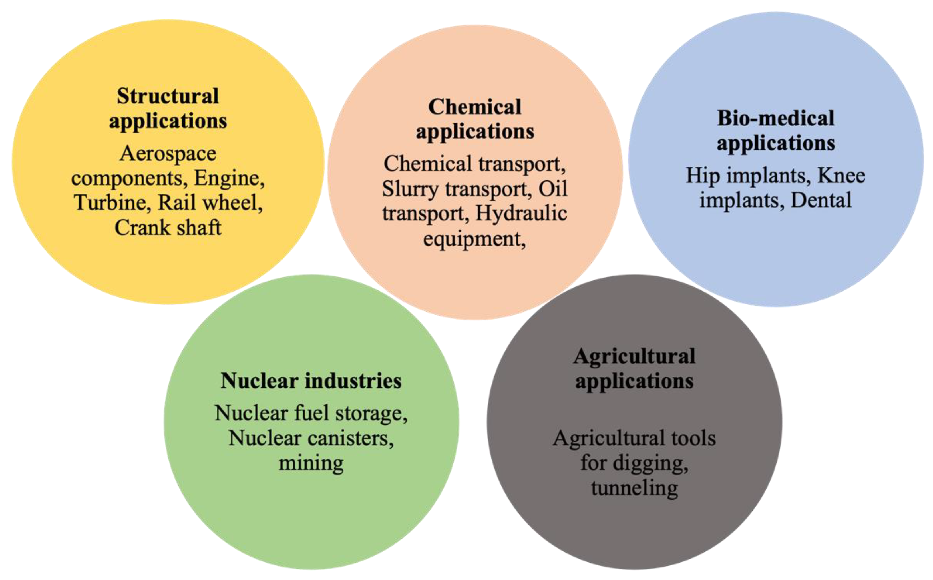
5. Applications of LC Process

LC is a promising potential method of coating technique which has diverse applications in various industries. It is predominantly used to enhance the surface properties and repair worn-out parts of mechanical components operating in extreme and challenging environmental conditions. LC is commonly used in mechanical equipment in slurry transport systems, oil industries, hydroelectric power plants, coal transportation systems, and aerospace, automotive, and nuclear industries. In the automotive industries, LC is carried out to enhance the fatigue behavior of conventional rail steel grades [85,86]. However, nowadays, mostly hypereutectoid steels are used as rail grade steels. Lai et al. [22] studied the effect of LC as a functional coating for repairing hypereutectoid railway steel. Their studies revealed improved mechanical properties and microstructural features for the repaired hypereutectoid railway steel. They reported enhanced consistency of microstructure across the rail head and HAZ, achieved by changing the cladding direction combined with a heat treatment procedure. Figure 16 shows the LC on the hypereutectoid railway steel. Zhu et al. [87] reported that LC could be used as an efficient method to repair local defects on railway wheels. Piasecki et al. [88] demonstrated enhanced surface mechanical properties when Stellite 6 was cladded on a crankshaft pulley hub. Chen et al. [89] reported wear-resistant coatings of CPM 9V tool steel on hardened H13 substrate.
In aerospace industries, LC is carried out to obtain high-temperature-resistant coatings. Pereira et al. [90] performed cladding of MCrAlY alloys (where M = Ni, Co, Fe or combinations of these) on austenitic stainless steel and studied the high-temperature oxidation behavior. The authors reported superior corrosion resistance of these coatings at high temperatures. The authors observed the formation of an oxide layer at a high temperature which protects the coating and substrate. Rottwinkel [91] demonstrated that LC could be used as a repair method to eliminate the formation of cracks in single crystal turbine blades. Sexton et al. [35] reported LC as popular repair technology for gas turbine engines. They demonstrated that LC could produce pore-free and crack-free coatings on Inconel 713 using Inconel 625 powders. Shepeleva et al. [34] performed LC on gas turbine engine blades and reported improved surface hardness which is attributed to the grain refinement during the LC process. Figure 17 demonstrates some potential applications of the LC process in diverse industries.
Quazi et al. [92] reported that LC could be carried out to develop self-lubricating coatings on aerospace turbo machinery which is operating in challenging conditions. Hence, it can provide superior tribological properties. Bartkowski and Bartkowska [93] reported enhanced wear resistance of agricultural tools made of steel subjected to LC treatment with Stellite 6 and WC powders. These tools predominantly interact with soil and are subject to severe erosion. Highly wear-resistant coatings were observed on these steels because of the formation of hard phases. Singh et al. [28] demonstrated that slurry erosion is a potential threat to hydraulic components transporting it from one place to another. The authors recommended LC as the predominant coating technique for slurry-carrying hydraulic equipment. LC develops highly wear-resistant coatings to prevent slurry erosion. In another study, Singh et al. [94] studied the effect of LC parameters on slurry erosion behavior in stainless steel 410 coated with NiCrSiBC + 50WC powder. The authors reported that the clad layer possesses superior hardness, which improved the slurry erosion resistance. Paul et al. [95] demonstrated the LC of Colmonoy 5 and Metco-41C on 316 stainless steel. The authors reported improved cavitation erosion and slurry erosion properties. Wang et al. [96] suggested LC as a potential method to counter the erosion–corrosion wear behavior of mining machine components. Radionova et al. [97] demonstrated that the service life of the roller dies used for drawing titanium wires can be enhanced by increasing the wear resistance of the working surfaces of the rollers by deposition of WC–10Co–4Cr using a laser. The authors reported that laser treatment enhanced the wear resistance by seven times compared to the untreated roller. The review on LC of various materials onto different steels indicates that this is a prospective technique for the modification of the surface of steels. The steel surface could be modified with proper processing parameters to have high functional properties such as high hardness, wear resistance, corrosion resistance, and erosion resistance. However, more research is required to understand materials, processing variables, microstructures, and functional properties.

6. Conclusions

This review article elucidates a comprehensive overview of the LC process. LC is a potential method of coating that can provide superior surface properties to mechanical components expected to operate in extreme conditions. In addition, LC is considered a predominant repair technique for worn-out mechanical components. This review focuses on the LC process of low-carbon and high-alloy steels. The LC process, powder feeding methods of LC, and comparison with other coating techniques were explained. The influence of various coatings on wear, corrosion, and microhardness behavior of various substrates was discussed. The effect of LC on microstructural features and microstructural modification was summarized. The influence of LC in various industries such as automotive, aerospace, chemical, and nuclear industries was explained, and some potential applications were explored. This review article can provide better insight into the LC process of carbon and high-alloy steels used for various industrial applications.

Author Contributions

Conceptualization, U.B.K.; Methodology, M.J.; Writing—original draft preparation, M.J., U.B.K., P.L.M.; Writing—review and editing, M.J., U.B.K., P.L.M.; Supervision, U.B.K., P.L.M. All authors have read and agreed to the published version of the manuscript.

Funding

This research received no external funding.

Institutional Review Board Statement

Not applicable.

Informed Consent Statement

Not applicable.

Data Availability Statement

Data sharing is not applicable to this article.

Acknowledgments

The authors acknowledge the Department of Mechanical Engineering, University of Nevada, Reno and Metallurgical and Materials Engineering, National Institute of Technology, Karnataka for providing all research facilities.

Conflicts of Interest

The authors declare no conflict of interest.

Abbreviations

ACAlternating Current
COFCoefficient of Friction
CPM Crucible Particle Metallurgy
DCDirect Current
FSPFriction Stir Processing
FSWFriction Stir Welding
LCLaser Cladding
SEMScanning Electron Microscopy
PEOPlasma Electrolytic Oxidation
UTSUltimate Tensile Strength
YSYield Strength

References

  1. Zhang, C.; Dong, Y.; Ye, C. Recent Developments and Novel Applications of Laser Shock Peening: A Review. Adv. Eng. Mater. 2021, 23, 2001216. [Google Scholar] [CrossRef]
  2. Kishore, A.; John, M.; Ralls, A.M.; Jose, S.A.; Kuruveri, U.B.; Menezes, P.L. Ultrasonic Nanocrystal Surface Modification: Processes, Characterization, Properties, and Applications. Nanomaterials 2022, 12, 1415. [Google Scholar] [CrossRef]
  3. John, M.; Ralls, A.M.; Dooley, S.C.; Thazhathidathil, A.K.V.; Perka, A.K.; Kuruveri, U.B.; Menezes, P.L. Ultrasonic Surface Rolling Process: Properties, Characterization, and Applications. Appl. Sci. 2021, 11, 10986. [Google Scholar] [CrossRef]
  4. Bhat, K.U.; Panemangalore, D.B.; Kuruveri, S.B.; John, M.; Menezes, P.L. Surface Modification of 6xxx Series Aluminum Alloys. Coatings 2022, 12, 180. [Google Scholar] [CrossRef]
  5. Kushwaha, A.K.; John, M.; Misra, M.; Menezes, P.L. Nanocrystalline Materials: Synthesis, Characterization, Properties, and Applications. Crystals 2021, 11, 1317. [Google Scholar] [CrossRef]
  6. John, M.; Diaz, O.; Esparza, A.; Fliegler, A.; Ocenosak, D.; Van Dorn, C.; Bhat, K.U.; Menezes, P.L. Welding Techniques for High Entropy Alloys: Processes, Properties, Characterization, and Challenges. Materials 2022, 15, 2273. [Google Scholar] [CrossRef]
  7. John, M.; Kalvala, P.R.; Misra, M.; Menezes, P.L. Peening Techniques for Surface Modification: Processes, Properties, and Applications. Materials 2021, 14, 3841. [Google Scholar] [CrossRef]
  8. Azhari, A.; Sulaiman, S.; Rao, A.K.P. A Review on the Application of Peening Processes for Surface Treatment. IOP Conf. Ser. Mater. Sci. Eng. 2016, 114, 012002. [Google Scholar] [CrossRef]
  9. Koshuro, V.; Fomina, M.; Fomin, A. High-Hardness Carbide Coatings and Their Production on X82WMoCrV6-5-4 Steel Using Induction Physical Vapor Deposition. Compos. Struct. 2022, 281, 115045. [Google Scholar] [CrossRef]
  10. An, Q.; Chen, J.; Tao, Z.; Ming, W.; Chen, M. Experimental Investigation on Tool Wear Characteristics of PVD and CVD Coatings during Face Milling of Ti 6242S and Ti-555 Titanium Alloys. Int. J. Refract. Met. Hard Mater. 2020, 86, 105091. [Google Scholar] [CrossRef]
  11. Daram, P.; Banjongprasert, C. The Influence of Post Treatments on the Microstructure and Corrosion Behavior of Thermally Sprayed NiCrMoAl Alloy Coating. Surf. Coat. Technol. 2020, 384, 125166. [Google Scholar] [CrossRef]
  12. Kuo, T.-Y.; Chin, W.-H.; Chien, C.-S.; Hsieh, Y.-H. Mechanical and Biological Properties of Graded Porous Tantalum Coatings Deposited on Titanium Alloy Implants by Vacuum Plasma Spraying. Surf. Coat. Technol. 2019, 372, 399–409. [Google Scholar] [CrossRef]
  13. Ralls, A.M.; Daroonparvar, M.; Sikdar, S.; Rahman, M.H.; Monwar, M.; Watson, K.; Kay, C.M.; Menezes, P.L. Tribological and Corrosion Behavior of High Pressure Cold Sprayed Duplex 316 L Stainless Steel. Tribol. Int. 2022, 169, 107471. [Google Scholar] [CrossRef]
  14. Wu, J.; Mao, C.; Wei, K.; Hu, J. Titanium-Modified Plasma Nitriding Layer and Enhanced Properties for 42CrMo Steel. J. Mater. Res. Technol. 2022, 18, 3819–3825. [Google Scholar] [CrossRef]
  15. Sezgin, C.T.; Hayat, F. The Effects of Boriding Process on Tribological Properties and Corrosive Behavior of a Novel High Manganese Steel. J. Mater. Processing Technol. 2022, 300, 117421. [Google Scholar] [CrossRef]
  16. Wan, H.; Lu, H.; Ren, Y.; Ma, C.; Chen, Y.; Xin, Z.; Cheng, L.; He, K.; Tu, X.; Han, Q.; et al. Strengthening Mechanisms and Tensile Properties of 20Cr2Mn2Mo Processed by Laser Shock Peening and Vacuum Carbonitriding. Surf. Coat. Technol. 2022, 439, 128462. [Google Scholar] [CrossRef]
  17. Yan, Y.; Luo, Z.; Liu, K.; Zhang, C.; Wang, M.; Wang, X. Effect of Cryogenic Treatment on the Microstructure and Wear Resistance of 17Cr2Ni2MoVNb Carburizing Gear Steel. Coatings 2022, 12, 281. [Google Scholar] [CrossRef]
  18. Cacko, R.; Chmielewski, T.; Hudycz, M.; Golański, D. New Approach of Friction AlN Ceramics Metallization with the Initial FEM Verification. Archiv. Civ. Mech. Eng. 2020, 20, 90. [Google Scholar] [CrossRef]
  19. Draper, C.W.; Poate, J.M. Laser Surface Alloying. Int. Met. Rev. 1985, 30, 85–108. [Google Scholar] [CrossRef]
  20. Jiang, W.; Wang, S.; Deng, Y.; Guo, X. Microstructure Stability and High Temperature Wear Behavior of an Austenite Aging Steel Coating by Laser Cladding. Mater. Charact. 2022, 184, 111700. [Google Scholar] [CrossRef]
  21. Zhu, L.; Xue, P.; Lan, Q.; Meng, G.; Ren, Y.; Yang, Z.; Xu, P.; Liu, Z. Recent Research and Development Status of Laser Cladding: A Review. Opt. Laser Technol. 2021, 138, 106915. [Google Scholar] [CrossRef]
  22. Lai, Q.; Abrahams, R.; Yan, W.; Qiu, C.; Mutton, P.; Paradowska, A.; Soodi, M. Investigation of a Novel Functionally Graded Material for the Repair of Premium Hypereutectoid Rails Using Laser Cladding Technology. Compos. Part B Eng. 2017, 130, 174–191. [Google Scholar] [CrossRef]
  23. Nie, M.H.; Zhang, S.; Wang, Z.Y.; Zhang, C.H.; Chen, H.T.; Chen, J. Effect of Laser Power on Microstructure and Interfacial Bonding Strength of Laser Cladding 17-4PH Stainless Steel Coatings. Mater. Chem. Phys. 2022, 275, 125236. [Google Scholar] [CrossRef]
  24. Leunda, J.; Soriano, C.; Sanz, C.; Navas, V.G. Laser Cladding of Vanadium-Carbide Tool Steels for Die Repair. Phys. Procedia 2011, 12, 345–352. [Google Scholar] [CrossRef]
  25. Cui, C.; Nie, J.; Li, Y.; Guan, Q.; Cai, J.; Zhang, P.; Wu, J. Wear Resistance of FeCrAlNbNi Alloyed Zone via Laser Surface Alloying on 304 Stainless Steel. Metals 2022, 12, 467. [Google Scholar] [CrossRef]
  26. Wu, C.L.; Xu, T.Z.; Wang, Z.Y.; Zhang, C.H.; Zhang, S.; Ni, C.L.; Zhang, D.X. Laser Surface Alloying of FeCoCrAlNiTi High Entropy Alloy Composite Coatings Reinforced with TiC on 304 Stainless Steel to Enhance Wear Behavior. Ceram. Int. 2022, 48, 20690–20698. [Google Scholar] [CrossRef]
  27. Lia, F.; Park, J.; Tressler, J.; Martukanitz, R. Partitioning of Laser Energy during Directed Energy Deposition. Addit. Manuf. 2017, 18, 31–39. [Google Scholar] [CrossRef]
  28. Singh, S.; Goyal, D.K.; Kumar, P.; Bansal, A. Laser Cladding Technique for Erosive Wear Applications: A Review. Mater. Res. Express 2020, 7, 012007. [Google Scholar] [CrossRef]
  29. Basu, A.; Samant, A.N.; Harimkar, S.P.; Majumdar, J.D.; Manna, I.; Dahotre, N.B. Laser Surface Coating of Fe–Cr–Mo–Y–B–C Bulk Metallic Glass Composition on AISI 4140 Steel. Surf. Coat. Technol. 2008, 202, 2623–2631. [Google Scholar] [CrossRef]
  30. Sugiyama, K.; Harada, K.; Hattori, S. Influence of Impact Angle of Solid Particles on Erosion by Slurry Jet. Wear 2008, 265, 713–720. [Google Scholar] [CrossRef]
  31. Wang, S.L.; Zhang, Z.Y.; Gong, Y.B.; Nie, G.M. Microstructures and Corrosion Resistance of Fe-Based Amorphous/Nanocrystalline Coating Fabricated by Laser Cladding. J. Alloys Compd. 2017, 728, 1116–1123. [Google Scholar] [CrossRef]
  32. Lepski, D.; Brückner, F. Laser Cladding. In The Theory of Laser Materials Processing; Dowden, J., Ed.; Springer Series in Materials Science; Springer: Dordrecht, The Netherlands, 2009; Volume 119, pp. 235–279. ISBN 978-1-4020-9339-5. [Google Scholar]
  33. Wang, Q.; Zeng, X.; Chen, C.; Lian, G.; Huang, X. An Integrated Method for Multi-Objective Optimization of Multi-Pass Fe50/TiC Laser Cladding on AISI 1045 Steel Based on Grey Relational Analysis and Principal Component Analysis. Coatings 2020, 10, 151. [Google Scholar] [CrossRef]
  34. Shepeleva, L.; Medres, B.; Kaplan, W.D.; Bamberger, M.; Weisheit, A. Laser Cladding of Turbine Blades. Surf. Coat. Technol. 2000, 125, 45–48. [Google Scholar] [CrossRef]
  35. Sexton, L.; Lavin, S.; Byrne, G.; Kennedy, A. Laser Cladding of Aerospace Materials. J. Mater. Processing Technol. 2002, 122, 63–68. [Google Scholar] [CrossRef]
  36. Pei, Y.T.; De Hosson, J.T.M. Functionally Graded Materials Produced by Laser Cladding. Acta Mater. 2000, 48, 2617–2624. [Google Scholar] [CrossRef]
  37. Barekat, M.; Shoja Razavi, R.; Ghasemi, A. Nd:YAG Laser Cladding of Co–Cr–Mo Alloy on γ-TiAl Substrate. Opt. Laser Technol. 2016, 80, 145–152. [Google Scholar] [CrossRef]
  38. Parekh, R.; Buddu, R.K.; Patel, R.I. Multiphysics Simulation of Laser Cladding Process to Study the Effect of Process Parameters on Clad Geometry. Procedia Technol. 2016, 23, 529–536. [Google Scholar] [CrossRef]
  39. Li, M.; Han, B.; Song, L.; He, Q. Enhanced Surface Layers by Laser Cladding and Ion Sulfurization Processing towards Improved Wear-Resistance and Self-Lubrication Performances. Appl. Surf. Sci. 2020, 503, 144226. [Google Scholar] [CrossRef]
  40. Vilar, R. Laser Cladding. J. Laser Appl. 1999, 11, 64–79. [Google Scholar] [CrossRef]
  41. Gupta, D.; Mordike, B.L.; Shariff, S.M.; Padmanabhan, G.; Manna, I.; Majumdar, J.D. Laser Surface Cladding of EN19 Steel with Stellite 6 for Improved Wear Resistance. Lasers in Eng. 2010, 19, 317–330. [Google Scholar]
  42. Liu, H.; Li, X.; Hua, P.; Song, K.; Teng, P.; Zhou, W. Microstructure and Properties of Laser-Cladded Fe50Mn30Co10Cr10 High Entropy Alloy Coatings. J. Spray Tech. 2022, 31, 991–999. [Google Scholar] [CrossRef]
  43. Wang, H.; Cheng, Y.; Zhang, X.; Yang, J.; Cao, C. Effect of Laser Scanning Speed on Microstructure and Properties of Fe Based Amorphous/Nanocrystalline Cladding Coatings. Mater. Chem. Phys. 2020, 250, 123091. [Google Scholar] [CrossRef]
  44. Han, L.; Phatak, K.M.; Liou, F.W. Modeling of Laser Cladding with Powder Injection. Met. Mater. Trans. B 2004, 35, 1139–1150. [Google Scholar] [CrossRef]
  45. Liu, Y.; Ding, Y.; Yang, L.; Sun, R.; Zhang, T.; Yang, X. Research and Progress of Laser Cladding on Engineering Alloys: A Review. J. Manuf. Processes 2021, 66, 341–363. [Google Scholar] [CrossRef]
  46. Hung, C.-F.; Lin, J. Solidification Model of Laser Cladding with Wire Feeding Technique. J. Laser Appl. 2004, 16, 140–146. [Google Scholar] [CrossRef]
  47. Hofman, J.T.; De Lange, D.F.; Pathiraj, B.; Meijer, J. FEM Modeling and Experimental Verification for Dilution Control in Laser Cladding. J. Mater. Processing Technol. 2011, 211, 187–196. [Google Scholar] [CrossRef]
  48. Wu, Z.; Qian, M.; Brandt, M.; Matthews, N. Ultra-High-Speed Laser Cladding of Stellite® 6 Alloy on Mild Steel. JOM 2020, 72, 4632–4638. [Google Scholar] [CrossRef]
  49. Shen, F.; Tao, W.; Li, L.; Zhou, Y.; Wang, W.; Wang, S. Effect of Microstructure on the Corrosion Resistance of Coatings by Extreme High Speed Laser Cladding. Appl. Surf. Sci. 2020, 517, 146085. [Google Scholar] [CrossRef]
  50. Song, C.; Wang, W.; Ren, Z.; Zhao, Y.; Zhou, L. Numerical and Experimental Study on the Properties of Laser Cladding of 6061Al Alloy. Trans. Indian Inst. Met. 2022, 75, 1355–1364. [Google Scholar] [CrossRef]
  51. Jin, L.; Jiang, K.; Kang, L.; Yan, B. Laser Cladding on Copper with Composite Powder C-Al2O3-Cu. J. Mater. Eng. Perform. 2022, 31, 1317–1324. [Google Scholar] [CrossRef]
  52. Liu, J.; Yu, H.; Chen, C.; Weng, F.; Dai, J. Research and Development Status of Laser Cladding on Magnesium Alloys: A Review. Opt. Lasers Eng. 2017, 93, 195–210. [Google Scholar] [CrossRef]
  53. Liu, Y.; Wang, Q.; Xie, J.; Yang, X.; Peng, P.; Wang, Y.; Li, M.; Ryu, C.H.; Joo, Y.H.; Jeong, I.W.; et al. Enhanced Surface Composite Coating on Ti811 Alloy by Laser Cladding towards Improved Nano-Hardness. Ceram. Int. 2022, 48, 18773–18783. [Google Scholar] [CrossRef]
  54. Cheng, F.T.; Lo, K.H.; Man, H.C. NiTi Cladding on Stainless Steel by TIG Surfacing Process Part II. Corrosion Behavior. Surf. Coat. Technol. 2003, 172, 316–321. [Google Scholar] [CrossRef]
  55. Giudice, F.; Sili, A. Weld Metal Microstructure Prediction in Laser Beam Welding of Austenitic Stainless Steel. Appl. Sci. 2021, 11, 1463. [Google Scholar] [CrossRef]
  56. Missori, S.; Sili, A. Prediction of Weld Metal Microstructure in Laser Beam Welded Clad Steel. Metallurgist 2018, 62, 84–92. [Google Scholar] [CrossRef]
  57. Liu, C.; Liu, Z.; Gao, Y.; Zheng, C.; Wang, X. Investigation on the Corrosion Behavior of Ni-Cr-Mo-W-XSi Laser Cladding Coating in H2S Corrosion Environment. Appl. Surf. Sci. 2022, 578, 152061. [Google Scholar] [CrossRef]
  58. Almeida, N.C.; Candido, L.C.; Faria, G.L.; Fernandes de Lima, M.S.; Trindade, V.B. Laser Cladding and Thermal Spray Coatings on Steel Pipe Serving the Oil and Gas Industry. J. Mater. Sci. Eng. 2016, 5, 2169-0022. [Google Scholar] [CrossRef]
  59. Du, B.; Zou, Z.; Wang, X.; Qu, S. Laser Cladding of in Situ TiB2/Fe Composite Coating on Steel. Appl. Surf. Sci. 2008, 254, 6489–6494. [Google Scholar] [CrossRef]
  60. Li, J.; Zhu, Z.; Peng, Y.; Shen, G. A Comparative Study on Microstructure Evolution and Wear Resistance of Different-Sized Tungsten Carbide Modified Fe-Based Laser Cladding Coatings. Opt. Laser Technol. 2022, 147, 107672. [Google Scholar] [CrossRef]
  61. Furukawa, M.; Horita, Z.; Nemoto, M.; Valiev, R.Z.; Langdon, T.G. Microhardness Measurements and the Hall-Petch Relationship in an AlMg Alloy with Submicrometer Grain Size. Acta Mater. 1996, 44, 4619–4629. [Google Scholar] [CrossRef]
  62. Li, K.; Li, D.; Liu, D.; Pei, G.; Sun, L. Microstructure Evolution and Mechanical Properties of Multiple-Layer Laser Cladding Coating of 308L Stainless Steel. Appl. Surf. Sci. 2015, 340, 143–150. [Google Scholar] [CrossRef]
  63. Zhang, H.; Shi, Y.; Kutsuna, M.; Xu, G.J. Laser Cladding of Colmonoy 6 Powder on AISI316L Austenitic Stainless Steel. Nucl. Eng. Des. 2010, 240, 2691–2696. [Google Scholar] [CrossRef]
  64. Dutta Majumdar, J.; Kumar, A.; Li, L. Direct Laser Cladding of SiC Dispersed AISI 316L Stainless Steel. Tribol. Int. 2009, 42, 750–753. [Google Scholar] [CrossRef]
  65. Zhang, B.; He, B.; Wang, H. Microstructural Investigation and Mechanical Performance of Laser Cladding Repaired Bainite Steel with AerMet100 Steel. Surf. Coat. Technol. 2022, 440, 128498. [Google Scholar] [CrossRef]
  66. Liu, J.; Li, J.; Cheng, X.; Wang, H. Microstructures and Tensile Properties of Laser Cladded AerMet100 Steel Coating on 300 M Steel. J. Mater. Sci. Technol. 2018, 34, 643–652. [Google Scholar] [CrossRef]
  67. Srisungsitthisunti, P.; Kaewprachum, B.; Yang, Z.; Gao, G. Real-Time Quality Monitoring of Laser Cladding Process on Rail Steel by an Infrared Camera. Metals 2022, 12, 825. [Google Scholar] [CrossRef]
  68. Huang, F.; Liu, E.; Qin, Y.; Wang, Q.; Jin, Y.; Wen, L.; Chang, H. A Study of Multi-Pass Laser-Cladding 2205 Duplex Stainless Steel Coating: Microstructure, Electrochemical Corrosion Behavior, and Wear-Resistance Properties. Coatings 2022, 12, 229. [Google Scholar] [CrossRef]
  69. Xu, P.; Lin, C.; Zhou, C.; Yi, X. Wear and Corrosion Resistance of Laser Cladding AISI 304 Stainless Steel/Al2O3 Composite Coatings. Surf. Coat. Technol. 2014, 238, 9–14. [Google Scholar] [CrossRef]
  70. El Cheikh, H.; Courant, B.; Branchu, S.; Huang, X.; Hascoët, J.-Y.; Guillén, R. Direct Laser Fabrication Process with Coaxial Powder Projection of 316L Steel. Geometrical Characteristics and Microstructure Characterization of Wall Structures. Opt. Lasers Eng. 2012, 50, 1779–1784. [Google Scholar] [CrossRef]
  71. Gargarella, P.; Almeida, A.; Vilar, R.; Afonso, C.R.M.; Peripolli, S.; Rios, C.T.; Bolfarini, C.; Botta, W.J.; Kiminami, C.S. Formation of Fe-Based Glassy Matrix Composite Coatings by Laser Processing. Surf. Coat. Technol. 2014, 240, 336–343. [Google Scholar] [CrossRef]
  72. Katakam, S.; Kumar, V.; Santhanakrishnan, S.; Rajamure, R.; Samimi, P.; Dahotre, N.B. Laser Assisted Fe-Based Bulk Amorphous Coating: Thermal Effects and Corrosion. J. Alloys Compd. 2014, 604, 266–272. [Google Scholar] [CrossRef]
  73. Hu, Y.L.; Lin, X.; Song, K.; Jiang, X.Y.; Yang, H.O.; Huang, W.D. Effect of Heat Input on Cracking in Laser Solid Formed DZ4125 Superalloy. Opt. Laser Technol. 2016, 86, 1–7. [Google Scholar] [CrossRef]
  74. Kołodziejczak, P.; Golański, D.; Chmielewski, T.; Chmielewski, M. Microstructure of Rhenium Doped Ni-Cr Deposits Produced by Laser Cladding. Materials 2021, 14, 2745. [Google Scholar] [CrossRef] [PubMed]
  75. Pereira, J.C.; Zambrano, J.C.; Rayón, E.; Yañez, A.; Amigó, V. Mechanical and Microstructural Characterization of MCrAlY Coatings Produced by Laser Cladding: The Influence of the Ni, Co and Al Content. Surf. Coat. Technol. 2018, 338, 22–31. [Google Scholar] [CrossRef]
  76. Kaul, R.; Ganesh, P.; Albert, S.K.; Jaiswal, A.; Lalla, N.P.; Gupta, A.; Paul, C.P.; Nath, A.K. Laser Cladding of Austenitic Stainless Steel with Hardfacing Alloy Nickel Base. Surf. Eng. 2003, 19, 269–273. [Google Scholar] [CrossRef]
  77. Tobar, M.J.; Amado, J.M.; Yáñez, A.; Pereira, J.C.; Amigó, V. Laser Cladding of MCrAlY Coatings on Stainless Steel. Phys. Procedia 2014, 56, 276–283. [Google Scholar] [CrossRef]
  78. Kusmoko, A.; Dunne, D.; Li, H.; Nolan, D. Laser Cladding of Stainless Steel Substrates with Stellite 6. MSF 2013, 773–774, 573–589. [Google Scholar] [CrossRef]
  79. Chen, J.; Xue, L. Laser Cladding of CPM Tool Steels on Hardened H13 Hot-Work Steel for Low-Cost High-Performance Automotive Tooling. JOM 2012, 64, 688–693. [Google Scholar] [CrossRef]
  80. Jiang, W.; Wang, S.; Wang, L. High Temperature Wear Performance of Laser Cladding Maraging Steel with Low Nickel on AISI H13 Steel. Proc. Inst. Mech. Eng. Part C J. Mech. Eng. Sci. 2021, 235, 7264–7272. [Google Scholar] [CrossRef]
  81. Altuncu, E.; Tarım, M. Laser Cladding of Martensitic Stainless Steels on Armor Steels. Emerg. Mater. Res. 2020, 9, 1–4. [Google Scholar] [CrossRef]
  82. Yan, Q.; Yang, K.; Wang, Z.; Chen, M.; Sun, G.; Ni, Z. Surface Roughness Optimization and High-Temperature Wear Performance of H13 Coating Fabricated by Extreme High-Speed Laser Cladding. Opt. Laser Technol. 2022, 149, 107823. [Google Scholar] [CrossRef]
  83. Hou, X.; Du, D.; Chang, B.; Ma, N. Influence of Scanning Speed on Microstructure and Properties of Laser Cladded Fe-Based Amorphous Coatings. Materials 2019, 12, 1279. [Google Scholar] [CrossRef] [PubMed]
  84. Rahman Rashid, R.A.; Barr, C.J.; Palanisamy, S.; Nazari, K.A.; Orchowski, N.; Matthews, N.; Dargusch, M.S. Effect of Clad Orientation on the Mechanical Properties of Laser-Clad Repaired Ultra-High Strength 300 M Steel. Surf. Coat. Technol. 2019, 380, 125090. [Google Scholar] [CrossRef]
  85. Niederhauser, S.; Karlsson, B. Fatigue Behaviour of Co–Cr Laser Cladded Steel Plates for Railway Applications. Wear 2005, 258, 1156–1164. [Google Scholar] [CrossRef]
  86. Wang, X.; Lei, L.; Yu, H. A Review on Microstructural Features and Mechanical Properties of Wheels/Rails Cladded by Laser Cladding. Micromachines 2021, 12, 152. [Google Scholar] [CrossRef]
  87. Zhu, Y.; Yang, Y.; Mu, X.; Wang, W.; Yao, Z.; Yang, H. Study on Wear and RCF Performance of Repaired Damage Railway Wheels: Assessing Laser Cladding to Repair Local Defects on Wheels. Wear 2019, 430–431, 126–136. [Google Scholar] [CrossRef]
  88. Piasecki, A.; Bartkowski, D.; Młynarczyk, A.; Dudziak, A.; Gościański, M.; Kasprowiak, M. Laser Cladding of Stellite 6 on Low Carbon Steel for Repairing Components in Automotive Applications Using Disk Laser. Arch. Mech. Technol. Autom. 2013, 33, 25–34. [Google Scholar]
  89. Chen, J.; Xue, L. Laser Cladding of Wear Resistant CPM 9V Tool Steel on Hardened H13 Substrate for Potential Automotive Tooling Applications. Mater. Sci. Technol. 2010, 2459–2470. [Google Scholar]
  90. Pereira, J.C.; Zambrano, J.C.; Tobar, M.J.; Yañez, A.; Amigó, V. High Temperature Oxidation Behavior of Laser Cladding MCrAlY Coatings on Austenitic Stainless Steel. Surf. Coat. Technol. 2015, 270, 243–248. [Google Scholar] [CrossRef]
  91. Rottwinkel, B.; Nölke, C.; Kaierle, S.; Wesling, V. Crack Repair of Single Crystal Turbine Blades Using Laser Cladding Technology. Procedia CIRP 2014, 22, 263–267. [Google Scholar] [CrossRef]
  92. Quazi, M.M.; Fazal, M.A.; Haseeb, A.S.M.A.; Yusof, F.; Masjuki, H.H.; Arslan, A. A Review to the Laser Cladding of Self-Lubricating Composite Coatings. Lasers Manuf. Mater. Process. 2016, 3, 67–99. [Google Scholar] [CrossRef]
  93. Bartkowski, D.; Bartkowska, A. Wear Resistance in the Soil of Stellite-6/WC Coatings Produced Using Laser Cladding Method. Int. J. Refract. Met. Hard Mater. 2017, 64, 20–26. [Google Scholar] [CrossRef]
  94. Singh, S.; Goyal, D.K.; Kumar, P.; Bansal, A. Influence of Laser Cladding Parameters on Slurry Erosion Performance of NiCrSiBC + 50WC Claddings. Int. J. Refract. Met. Hard Mater. 2022, 105, 105825. [Google Scholar] [CrossRef]
  95. Paul, C.P.; Gandhi, B.K.; Bhargava, P.; Dwivedi, D.K.; Kukreja, L.M. Cobalt-Free Laser Cladding on AISI Type 316L Stainless Steel for Improved Cavitation and Slurry Erosion Wear Behavior. J. Mater. Eng. Perform. 2014, 23, 4463–4471. [Google Scholar] [CrossRef]
  96. Wang, P.; Yang, Y.; Ding, G.; Qu, J.; Shao, H. Laser Cladding Coating against Erosion-Corrosion Wear and Its Application to Mining Machine Parts. Wear 1997, 209, 96–100. [Google Scholar] [CrossRef]
  97. Radionova, L.V.; Samodurova, M.N.; Sarafanov, A.E.; Bykov, V.A.; Glebov, L.A.; Pashkeev, K.Y. Elevation of the Wear Resistance of Roller Dies for the Production of Wires from Titanium Alloys. Metallurgist 2021, 64, 1188–1197. [Google Scholar] [CrossRef]
Figure 1. Copyright Elsevier, 2021. The LC process. Reproduced with permission from [33]. Copyright MDPI, 2021.
Coatings 12 01444 g001
Figure 2. LC process: (a) coaxial powder feeding, (b) preplaced powder, (c) off-axis powder feeding, (d) wire feeding. Reproduced with permission from [45]. Copyright Elsevier, 2021.
Coatings 12 01444 g002
Figure 3. Surface morphology of LC of 17-4 PH stainless steel on E355DD steel for three different laser powers, XY plane, (a) 2000 W, (b) 2200 W, and (c) 2400 W, YZ plane, (d) 2000 W, (e) 2200 W, and (f) 2400 W. Reproduced with permission from [23]. Copyright Elsevier, 2022.
Coatings 12 01444 g003
Figure 4. Variation in microhardness values of LC of 17-4 PH stainless steel on different E355DD steel specimens in the clad layer, interface, HAZ and substrate. Reproduced with permission from [23]. Copyright Elsevier, 2022.
Coatings 12 01444 g004
Figure 5. Macrograph of LC of TiB2/Fe composite coating on AISI 1010 steel: (a) top surface, (b) cross-section showing clad layer, HAZ, and substrate. Reproduced with permission from [59]. Copyright Elsevier, 2008.
Coatings 12 01444 g005
Figure 6. Variation in COF (a) and wear rate (b) of during LC of three clad layers of (Fe60 + WC) on 16 Mn steel based on WCs, WCl, and mix of WCs and WCl. Reproduced with permission from [60]. Copyright Elsevier, 2022.
Coatings 12 01444 g006
Figure 7. Scanning electron micrographs (SEMs) of the top surface of LC of Fe-Cr-Mo-Y-N-C on AISI 4140 substrate surfaces with a linear scan speed of 2.5 m/min and incident laser power of (a) 1.5 kW, (b) 2.0 kW. Reproduced with permission from [29]. Copyright Elsevier, 2008.
Coatings 12 01444 g007
Figure 8. SEMs of the cross-sections of the LC of FeCoCrMoCBY, onto mild steel substrate with different pulse frequencies: (a) 0.5 Hz, (b) 1.0 Hz, (c) 1.5 Hz, (d) 2.5 Hz. Reproduced with permission from [31]. Copyright Elsevier, 2017.
Coatings 12 01444 g008
Figure 9. Potentiodynamic polarization curves LC of FeCoCrMoCBY, onto mild steel substrate: (a) different pulse frequencies and (b) different laser powers. Reproduced with permission from [31]. Copyright Elsevier, 2017.
Coatings 12 01444 g009
Figure 10. Hardness variation in the clad, HAZ, and substrate during LC of 410L stainless steel on railroad steel. Reproduced with permission from [22]. Copyright Elsevier, 2017.
Coatings 12 01444 g010
Figure 11. SEM indicates good fusion at the interface between the cladding layer and the interface during LC of martensitic stainless steels on armor steels [81]. ICE Publishing, 2020.
Coatings 12 01444 g011
Figure 12. Optical micrograph presenting different zones during LC of CPM 10V on Vanadis 4 Extra tool steel plates (CZ: Clad zone, IZ: Interface zone, HAZ: Heat-affected zone, RHZ: Reheated zone). Reproduced with permission from [24]. Copyright Elsevier, 2011.
Coatings 12 01444 g012
Figure 13. Potentiodynamic polarization curves during cladding of AISI 431 grades (martensitic stainless steel) onto 27SiMn steel specimens corresponding to three laser scanning speeds. Reproduced with permission from [49]. Copyright Elsevier, 2020.
Coatings 12 01444 g013
Figure 14. Variation in microhardness (a), COF (b), and volume loss (c) of the substrate during LC of H13 coating on the 5CrNiMo substrate. Reproduced with permission from [82]. Copyright Elsevier, 2022.
Coatings 12 01444 g014
Figure 15. Cross-sectional micrograph of a single bead clad specimen during LC of (FeMoCrCoCBYSi) coating on 3Cr13 stainless steel substrates showing crystalline and amorphous regions during LC. Reproduced with permission from [83]. Copyright MDPI, 2019.
Coatings 12 01444 g015
Figure 16. Cladding on hypereutectoid railway steel. Reproduced with permission from [22]. Copyright Elsevier, 2017.
Coatings 12 01444 g016
Figure 17. Applications of LC process.
Coatings 12 01444 g017
Table 1. LC process on low-carbon and high-alloy steel.
Substrate/PowderLC ParametersObservation
316L stainless steel/308 stainless steel [62]IPG YLS—5000 fiber laser;
Laser power—4000 W;
Scanning speed—8 mm/s;
Wire feeding speed—40 mm/s;
Overlapping rate—49%; Interlayer-movement—1 mm
  • The coating is predominantly composed of columnar dendrite
  • No softening observed in HAZ
  • 86% and 74% higher tensile strength and elongation were observed for coating than the substrate
  • Dimples were observed in the fracture surface
AISI 316L/Calmonoy 6 [63]DAIHEN ELA-2001 axial-flow laser; Wavelength—10.6 μm; Carrier gas—Argon
  • Wear resistance increased by 53 times
  • COF of the clad layer is lower than the substrate
  • The microstructure is rich in Ni, boride, and carbide
AISI 316L/blend of SiC and AISI 316L [64]Laser line diode laser;
Laser power—1500W;
Spot size—3.5 mm × 2 mm;
Carrier gas—Argon
  • Defect-free homogenous layer observed
  • Increase in microhardness
  • Improved wear resistance
  • Abrasive failure observed
  • Partially dissociated SiC, Cr3C2, and Fe2Si in the clad layer
Bianite steel/AerMet100 steel [65]Laser power—4000 W;
Scanning speed—20 mm/s;
Beam diameter—6 mm;
Powder feeding rate—25 g/min;
Interlayer movement—1 mm
  • Repaired regions contain bainitic microstructure and corresponding hardness is 515 HV;
  • Repaired steel possesses structure similar to bainitic substrate
  • Improved wear resistance
  • Mass loss reduced by 28%
H13 steel/austenitic aging steel [20]Laser power—4000 W;
Scanning speed—5 mm/s;
Beam diameter—0.7 mm;
Overlapping rate—50%;
  • Superior thermal properties
  • Improved surface hardness
  • Microstructure of coatings composed of columnar and equiaxed grains
  • Improved high-temperature wear resistance
20G steel/Ni-Cr-Mo-W-xSi [57]Laser power—3000 W;
Scanning speed—10 cm/s;
Overlapping rate—50%;
Clad layer thickness—500 μm
  • Superior corrosion-resistant coating
  • Optimal Si content is 1 wt.% which increases the Mo and Cr in the inner layer and improves corrosion
300 M steel/AerMet 100 steel [66]Laser power—6400 W;
Scanning speed—300 mm/min;
Powder feed rate—1500 g/h;
Beam diameter—8 mm;
Overlapping rate—50%
  • Homogenous clad layer
  • Transition zone observed between HAZ and clad layer
  • The transition zone has fine bainitic microstructure, which changed to lath martensite
  • Ductile fracture observed in the clad layer and quasi-cleavage in HAZ
U75V, U20Mn/Inconel 625 [67]Laser power—500 W; 800 W; 1000 W;
Scanning speed—3 mm/s and 6 mm/s;
Powder feed rate—15 g/min;
Beam diameter—8 mm
  • Real-time monitoring of the LC process
  • Predicted microhardness and microstructure based on cooling rate and thermal gradient
  • Able to identify disturbance and geometry in real time.
Q235 carbon steel/2205 duplex stainless [68]Laser power—1900 W; 2100 W; 2300 W; 2500 W;
Beam diameter—5 mm;
Scanning speed—5 mm/s;
Overlapping rate—40%
  • Superior surface properties
  • No pores or cracks
  • Equiaxed crystals and cellular crystals were observed at high laser power
  • Corrosion potential is 27% and corrosion current is 4.1% of carbon steel
  • Wear behavior is improved
  • Lower COF
  • A combination of abrasive and adhesive wear is observed
45 steel/AISI 304 L stainless steel, 304/Al2O3 [69]
  • Laser power—2500 W;
  • Beam diameter—3 mm;
  • Scanning speed—800 mm/min;
  • Powder feed rate—0.05 g/s;
  • Overlapping rate—50%
  • Defect-free coating
  • Superior hardness, corrosion and wear resistance
  • The composite coating contains planar, cellular, and dendritic crystals
  • HAZ contains fine martensite and ferrite
  • Composite microhardness is 600 HV and that of 304 coating is 200 HV
  • Composite coating possesses superior wear resistance
Low-carbon steel/316 stainless steel [70]
  • Laser power—1900 W; 2100 W; 2300 W; 2500 W;
  • Beam diameter—5 mm;
  • Scanning speed—500–1500 mm/min;
  • Powder feed rate—0.05 g/s
  • Columnar dendrites present in the bottom layer
  • Equiaxed grains on top clad layer
  • Homogeneous microhardness in each layer
  • A correlation between process parameter and wall height is observed
Publisher’s Note: MDPI stays neutral with regard to jurisdictional claims in published maps and institutional affiliations.

