Article

Preparation and Tribological Properties of Graphene-Based Coatings on Tungsten Carbide

Mechanical and Electrical Engineering Institute, Zhengzhou University of Light Industry, Zhengzhou 450001, China
*
Author to whom correspondence should be addressed.
Coatings 2022, 12(10), 1385; https://doi.org/10.3390/coatings12101385
Submission received: 10 August 2022 / Revised: 8 September 2022 / Accepted: 17 September 2022 / Published: 22 September 2022

Abstract

:
The preparation technology of graphene-based coatings on cobalt-based cemented carbides and the friction properties of graphene-based coatings were researched. Based on cooling rate, growth temperature, and methane flow rate, Raman spectroscopy was used to evaluate the influence of chemical vapor deposition (CVD) on graphene-based coatings. The results show that at the growth temperature of 1000 °C, the cooling rate of 15 °C/min and methane flow rate of 10 sccm are more favorable for the growth of pure graphene coating with fewer layers on a cemented carbide surface. As methane flow boosts, the number of graphene layers increases and amorphous carbon is generated. The resulting tribological properties demonstrate that the friction coefficient of graphene-based coatings decreases as the friction load increases. The above results indicate that the graphene-based coating on a cemented carbide surface can be prepared by regulating its composition and defects through technological parameters, and it is viable to use graphene-based coating as anti-wear coating for cutting tools. The results provide a reference for the preparation and properties of cemented carbide surface graphene.

1. Introduction

The advent of coated cutting tools provides another way to resolve the abrasion resistance of cutting tools [1,2,3]. At present, the use of coated cutting tools has surpassed 50% in the field of machining [4]. Coated tools are divided into two categories: “hard” coated tools and “soft” coated tools, according to the classification of the properties of the tool coating materials [5]. A “Hard” coated tool is created by strengthening the hardness of the tool surface in a “hard” way to prolong the service life of the tool; the tool and workpiece friction process is still very acute. A “Soft” coated tool is created with the use of coating material that has antifriction properties to decrease the friction coefficient between the tool and the workpiece, reduce the friction action, and reduce the cutting force and cutting temperature [1,6,7,8]. An important factor in determining the performance of coated tools is the physical and chemical properties of the coating material. A coating material with an outstanding self-lubricating property effectively protects the tool matrix, avoids the rapid wear of the tool matrix, and enhances the service life of the tool [9,10,11].
The strongest material known is graphene, which has a stable structure, high toughness, large specific surface area, and special lamellar structure of multilayer graphene with excellent self-lubricating properties [12,13]. It is due to the excellent physical and chemical properties of graphene that it has been used in semiconductors [14,15], energy [16,17], functional coating [18], composite materials [19], aerospace [20], and other fields [21,22]. Consequently, graphene material possesses excellent physical and chemical properties as a tool coating material in the tool industry and has important practical significance and practical value [23,24,25].
Berman et al. investigated the impact of graphene-based ethanol solution on the tribological properties of steel and demonstrated that graphene-based ethanol solution reduced the wear of steel by four orders of magnitude and lowered the friction coefficient by one sixth [26]. It is proved that graphene plays an important role in wear resistance and wear reduction [23,27]. The mechanism of friction reduction is that graphene forms a protective film that is easy to shear at the friction interface [28]. Graphene coating was prepared on the surface of copper foil by the CVD method. Dry friction experiments indicate that the wear resistance of graphene coated Copper foil is substantially upgraded, and the failure time node of the coating is prolonged with the increase of deposition time of graphene [29,30]. Kim et al. prepared monolayer and multilayer graphene on Cu and Ni surface and transferred them to a SiO2/Si substrate surface by CVD [31]. Under the friction load of 5~70 mN, both graphene films can effectively reduce the friction of the SiO2/Si matrix when in antithesis with the quartz material, and the friction reduction effect of multilayer graphene film is better. In addition, the results revealed that the friction interface formed a large number of graphene transfer films that acted as a solid lubrication films. Jiang et al. prepared copper–graphite composite coatings on AISI 52,100 and found that the coatings sustained comparatively stable low coefficients of friction under conditions of strong vibration (3Hz, 5 Hz, 8 Hz, 10 Hz, 12 Hz, and 15 Hz) and large shocks (10.0 N, 15.5 N, 31.0 N, 46.5 N, 62.0 N, and 77.5 N) [32]. Huang et al. prepared graphene nanostructures containing 6.2 vol.% on a Ni3Al matrix, and when the applied load was increased from 3 N to 18 N, the coefficient of friction and wear rate of the surface were significantly reduced due to the presence of graphene [33].
Graphene has excellent physical and chemical properties as a tool coating material applied to the coated tool field, but the related research is lacking. Hence, this study intends to use CVD technology to prepare graphene-based coatings on cemented carbide tool surfaces, characterize the tribological properties of graphene-based coatings, and investigate the effects of load and process parameters on the friction reduction effect of graphene-based coatings.

2. Materials and Experimental Section

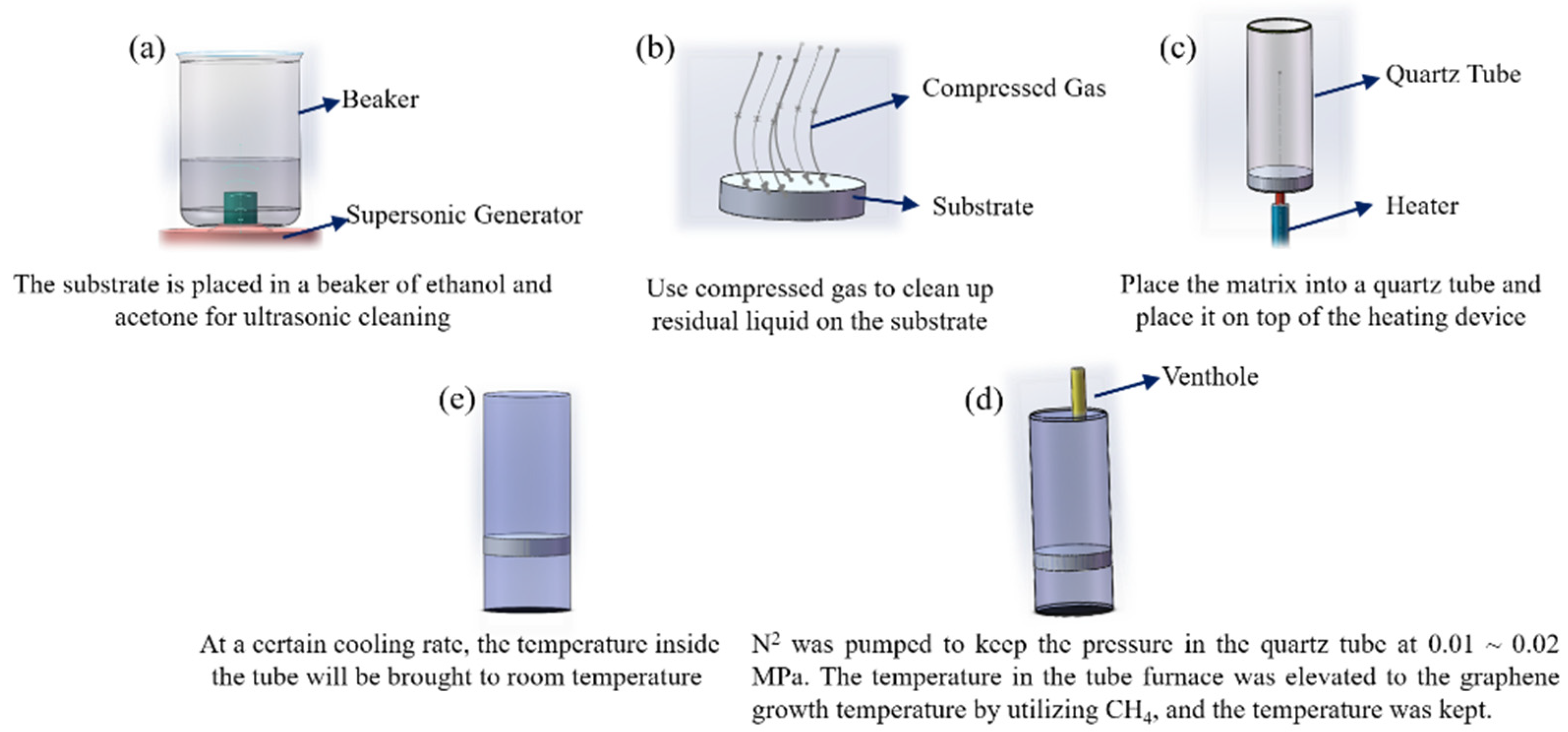
2.1. Materials and TBCs Preparation

In this research, the substrate material used for deposition coating is cemented carbide with 8 wt% cobalt content (YG8, Zhuzhou Cemented Carbide Group Co., Ltd., Zhuzhou, China), which is a φ 5 × 20 mm round rod, and the roughness of the end face of the round rod is Ra 3.2. The preparation process of the graphene-based coating is illustrated in Figure 1. Firstly, the substrate was cleaned by the ultrasonic method with ethanol and acetone for 10 min successively, and the surface of the substrate was blown dry with compressed air before being put into the crucible for use. Second, the crucible and matrix were put into the quartz tube of CVD and vacuumized. Then, 400 sccm of nitrogen was continuously pumped into the tube and the pressure in the quartz tube was maintained at 0.01~0.02 MPa. The temperature of the tubular furnace was elevated to the growth temperature. Then, CH4 was passed into the tubular furnace and the temperature maintained when the growth temperature of graphene was reached. Ultimately, the supply of methane was cut off at a certain rate. The microscopical laser Raman spectrometer (Renishaw (Shanghai) Trading Co., Ltd., Shanghai, China) was used to characterize the phase composition of graphene-based coatings and the number of graphene layers.

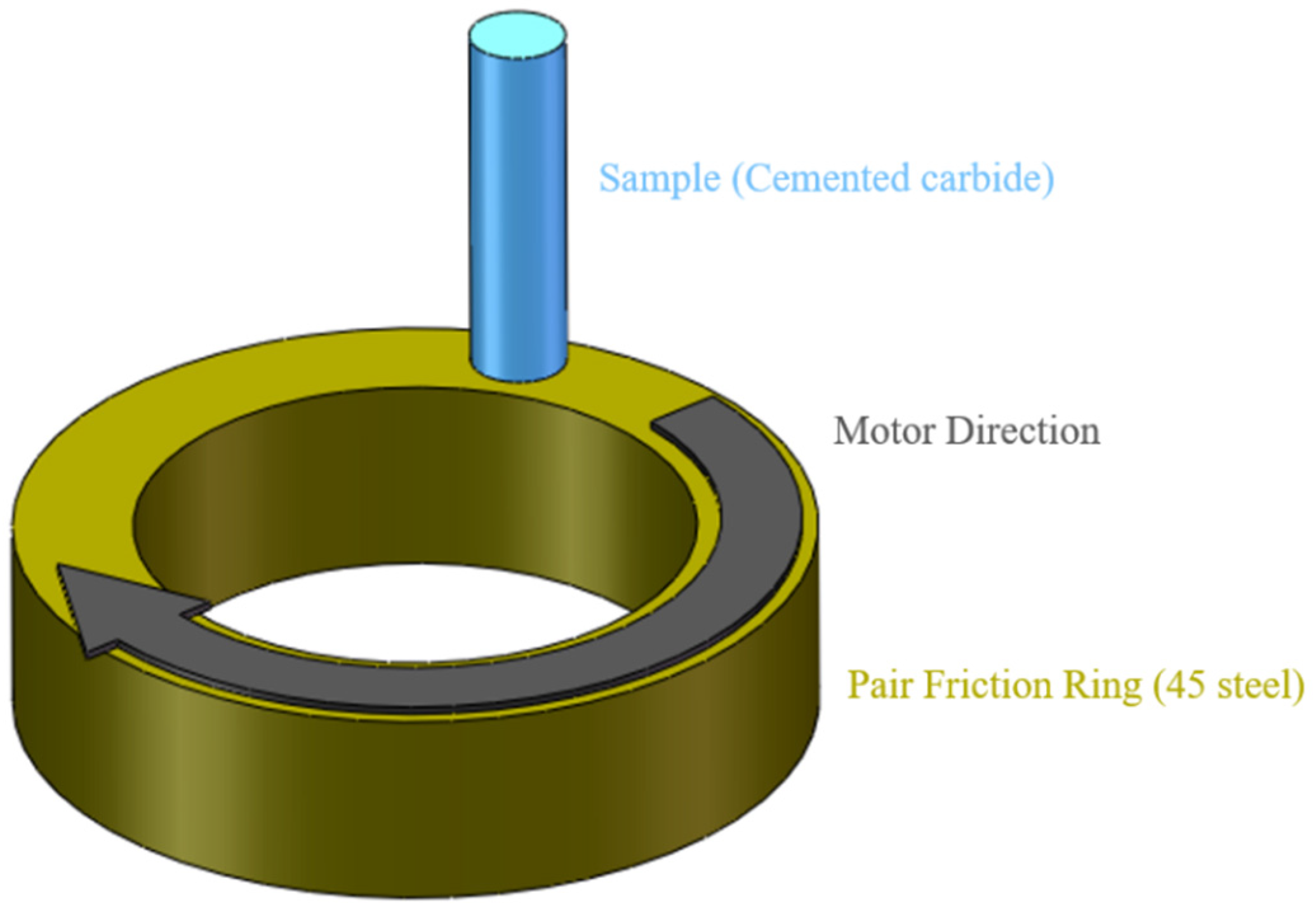
2.2. Friction Experiment

Friction experiments were carried out on a friction and wear testing machine (MMW-1 friction testing machine, Jinan Nair Testing Machine Co., Ltd., Jinan, China). The pin-disc friction form was used to test the friction properties of graphene-based coating tools prepared under various process parameters, as shown in Figure 2. For rubbing material, 45 steel common is selected in the market, and the end face of the ring is refined to guarantee that the roughness is Ra 3.2. The normal phase loads of friction experiments are 25 N, 50 N, 75 N, 100 N, and 125 N, respectively.
The morphology of the friction surface of the specimen was observed by using a Leica Digital Microscope DVM6 (Leica Microsystems GmbH, Wetzlar, Germany).

3. Results

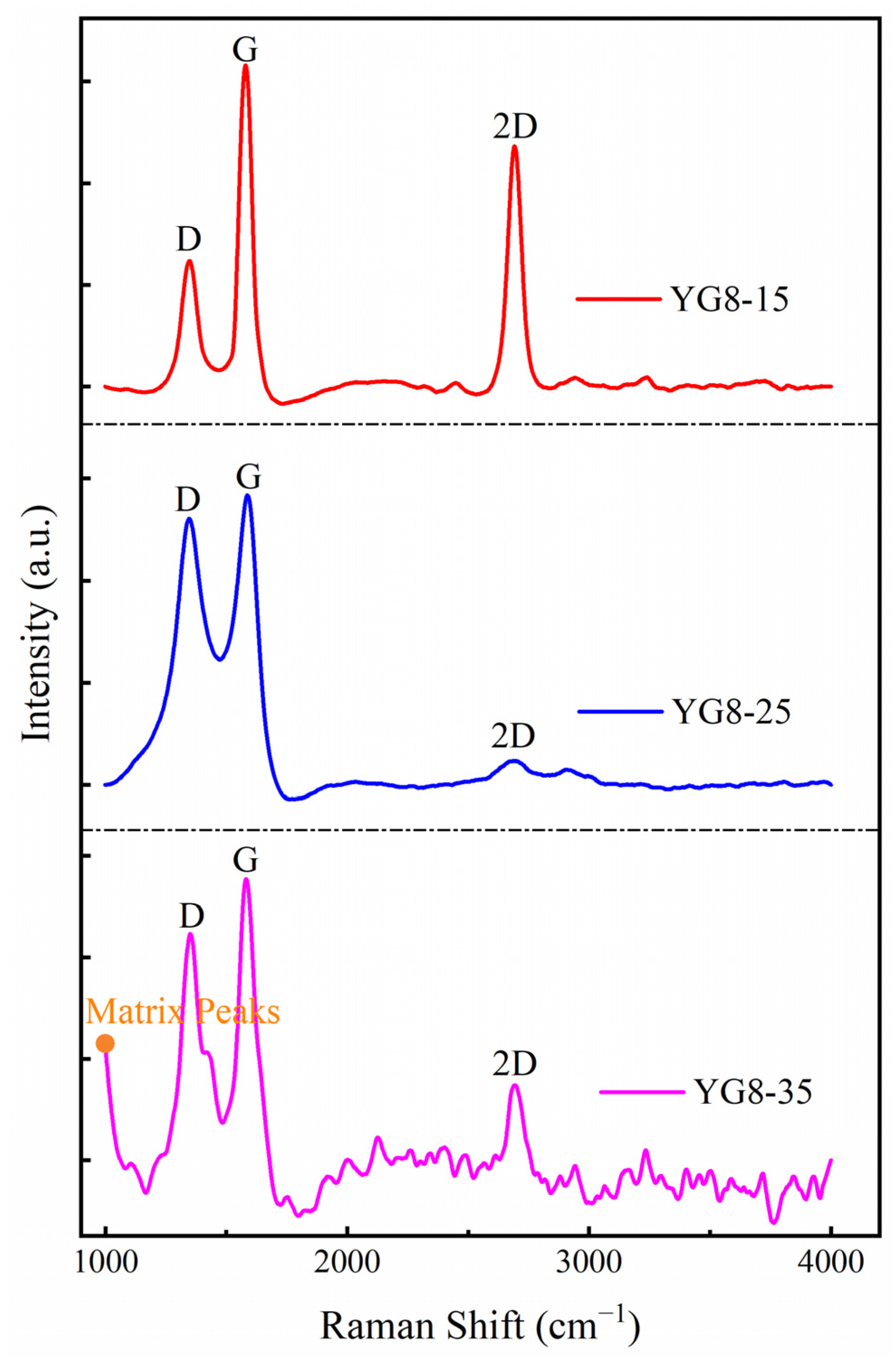
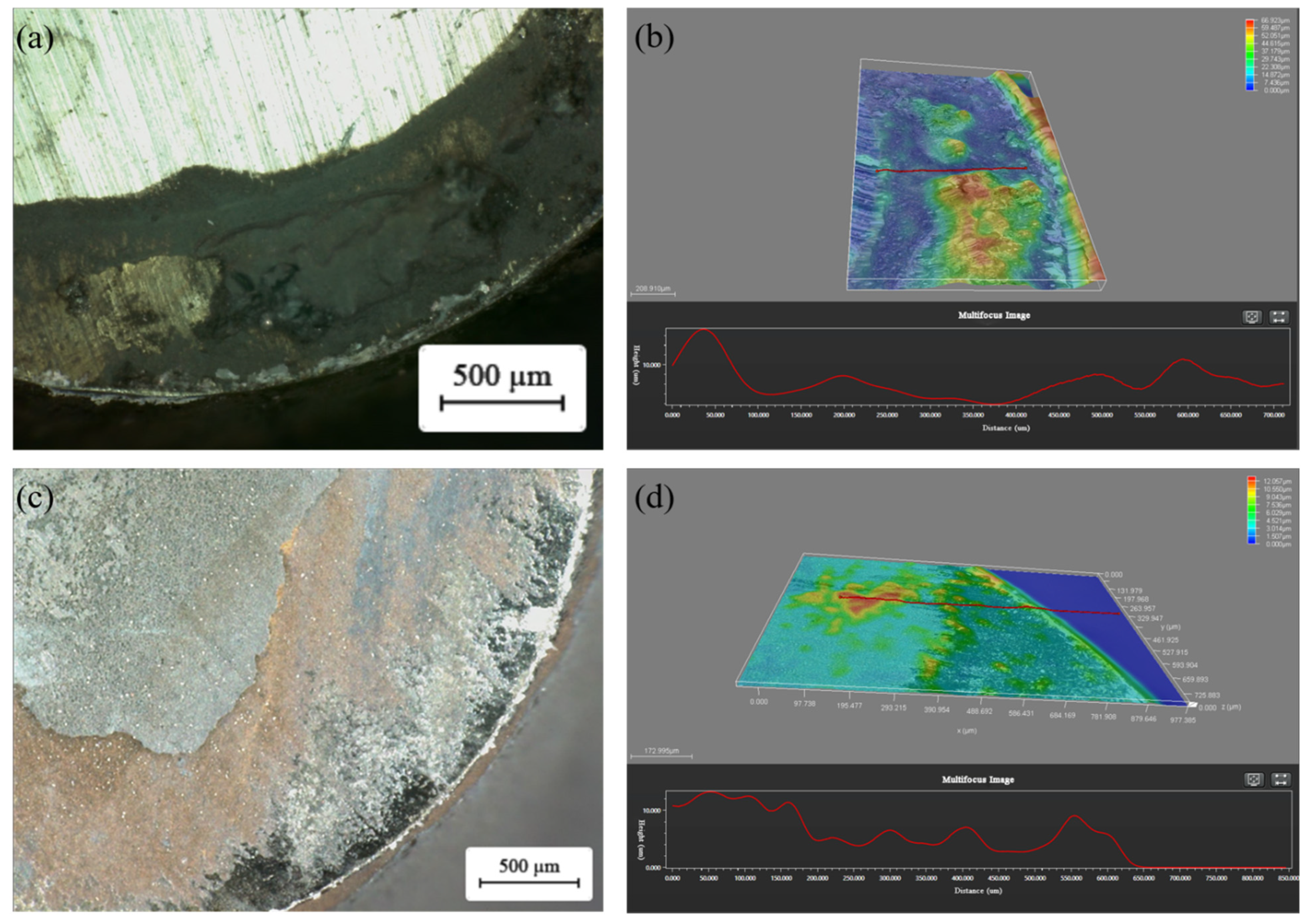
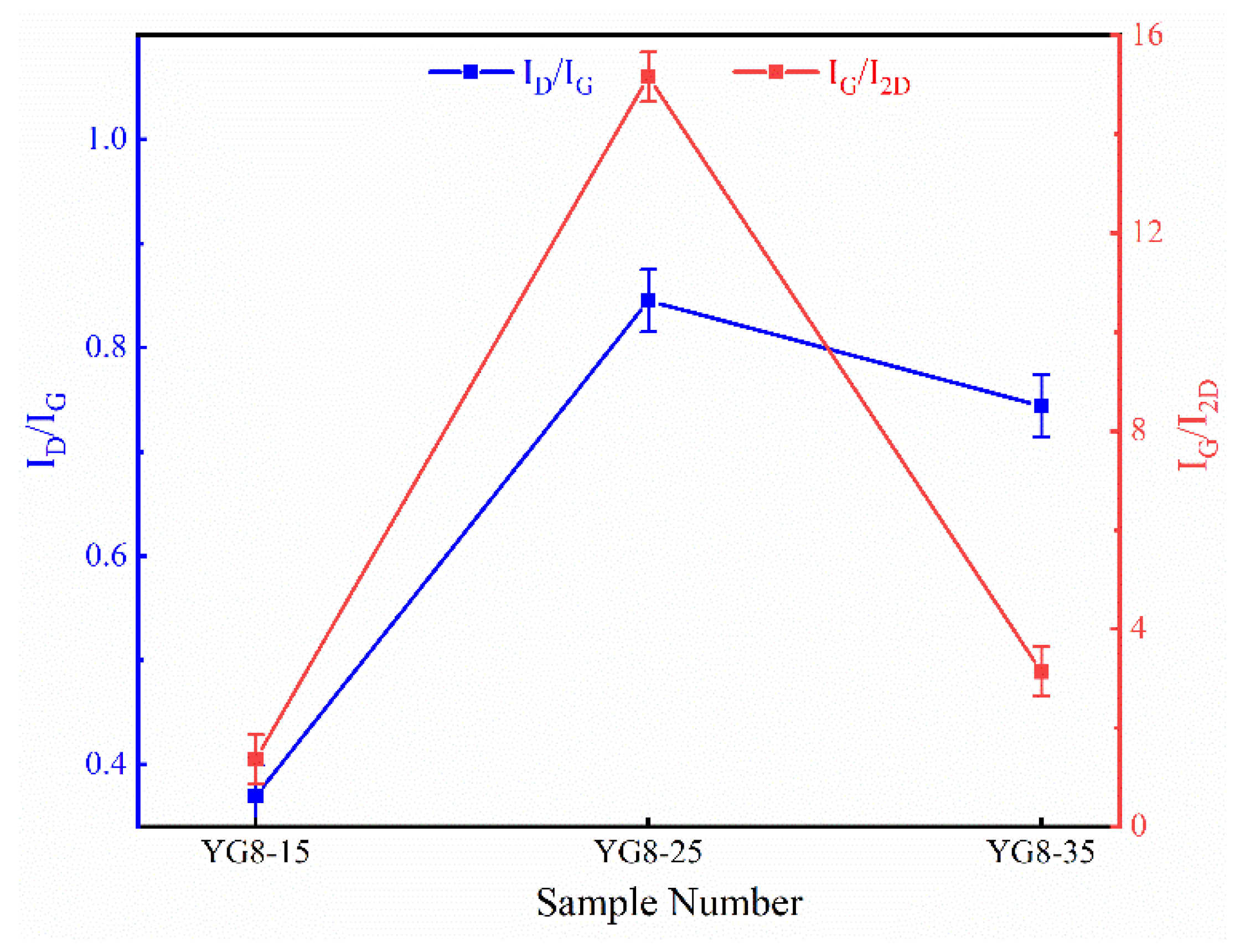
3.1. Effect of Cooling Rate on Deposition of Graphene-Based Coatings

The carbon dissolving capacity of cobalt and nickel is 3.41% and 2.03% at 1000 °C, so according to the “carburizing and carbon precipitation mechanism”, the cooling rate will affect the composition of graphene-based coating. To this end, cooling rates were set at 15 °C/min, 25 °C/min, and 35 °C/min, respectively (shown in Table 1), to survey the deposition of graphene-based coatings on tungsten carbide by cooling rate.
The results of the Raman spectrum are shown in Figure 3. As can be seen from Figure 3, the particular G peak and 2D peak of Graphene are detected on the YG8-15, YG8-25, and YG8-35 samples, while the D peak reflecting graphene defects also occurs. Raman spectrum results are affected by many factors, so the intensity of 2D peak and D peak between each sample is not analogous. The peak strength ratio of peak D to peak G (ID/IG) explains the defect density of graphene generated. The higher the ID/IG value, the higher the defect density of graphene. Similarly, the peak strength ratio of G peak to 2D peak (IG/I2D) indicates the number of graphene layers, which can be calculated by the formula [34]:
I G I 2 D = 0.14 + n 10
where, n is the number of layers of graphene. Therefore, the number of graphene layers increases with the increase of the IG/I2D value.
Figure 4 shows the ID/IG value and IG/I2D value of the three samples. The ID/IG value grows with the increase in the cooling rate, signaling that the increase in the cooling rate leads to an increase in the defect density of graphene films. The IG/I2D value reached the maximum when the cooling rate was 25 °C/min, and the IG/I2D value was basically the same when the cooling rate was 15 °C/min and 35 °C/min. The results show that YG8-25 has the most graphene layers.
Based on the above results, it can be observed that the graphene coating layers of the YG8-15 sample are narrow and the defect density is small. Although the carbon solubility of cobalt is superior to that of nickel at 1000 °C, there is not a linear relationship between the cooling rate and the graphene coating layers when preparing graphene from the YG8 matrix.

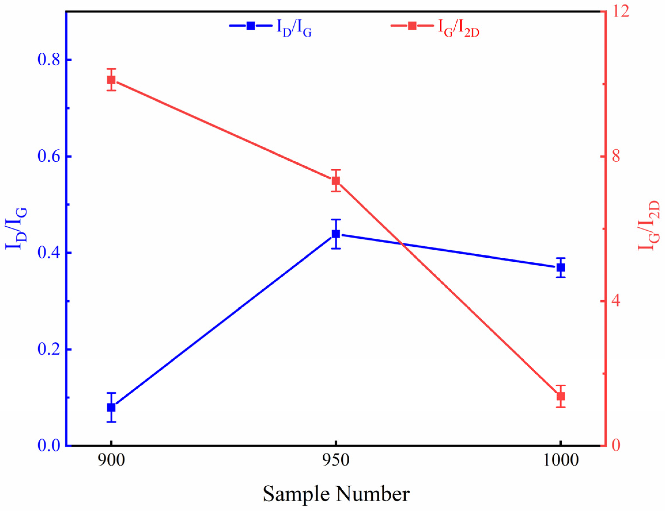
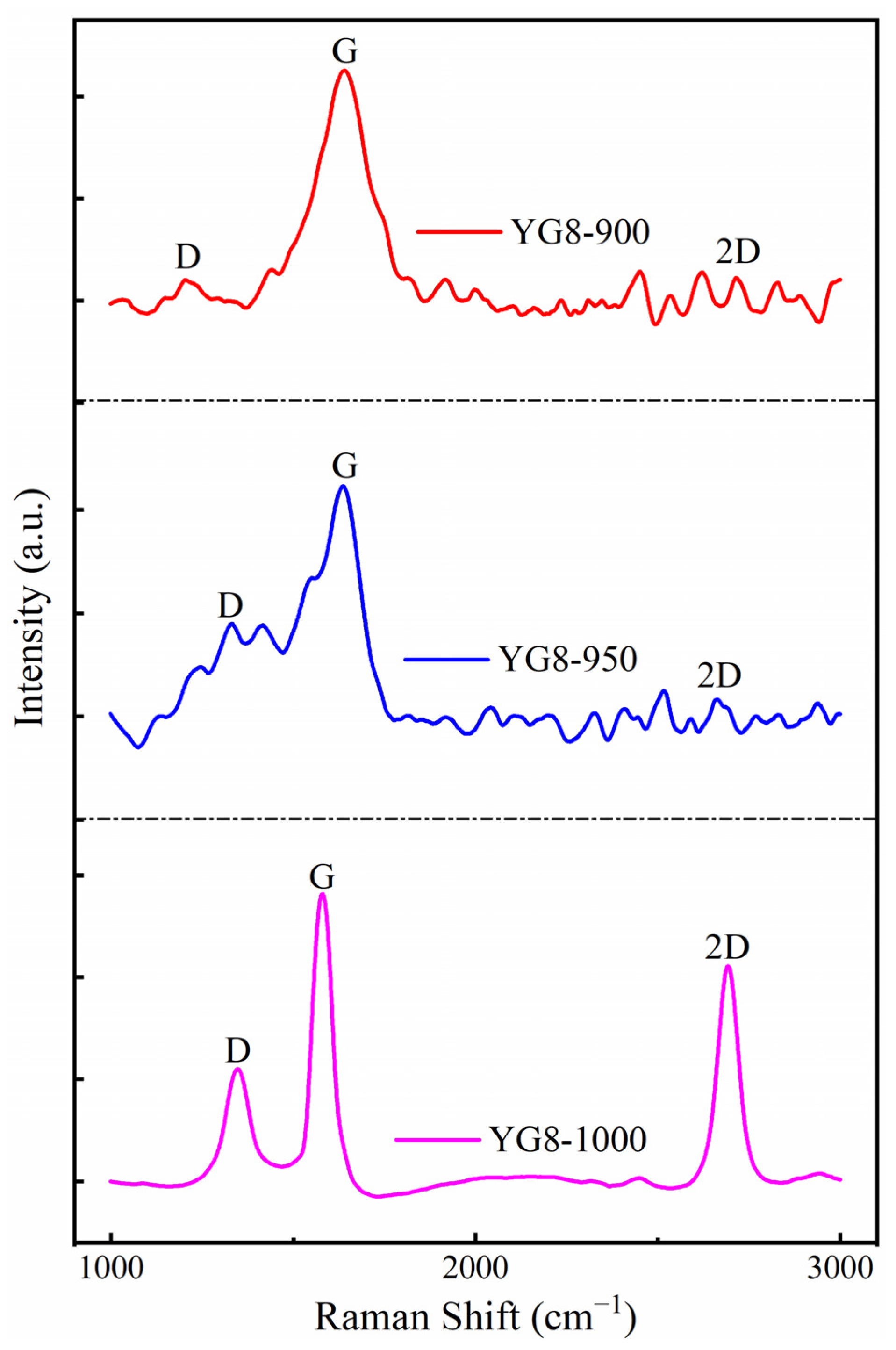
3.2. Effects of Growth Temperature on Deposition of Graphene-Based Coatings

The growth temperature mainly depends on the pyrolysis temperature of the carbon source. The pyrolysis temperature of methane is above 1100 °C without catalysis. In Section 3.1, the experiment shows that methane decomposes and produces graphene at 1000 °C. Consequently, growth temperatures of 900 °C, 950 °C, and 1000 °C are used to investigate their effects on graphene-based coatings, respectively. Table 2 illustrates the specific empirical parameters.
The results of the Raman spectrum are shown in Figure 5. The Raman results of YG8-900 and YG8-950 showed the presence of matrix peaks, and 2D peaks were not obvious. The Raman results of YG8-1000 showed the characteristics of graphene with few layers. This indicates that the pyrolysis capacity of methane is weak at 900 °C and 950 °C, and sufficient carbon atoms are not generated within 10 min to cover the substrate surface with graphene. Figure 6 shows the ID/IG and IG/I2D values of the three samples, respectively. The ID/IG value of YG8-900 and YG8-950 samples is much higher than that of YG8-1000 samples. The defect density of graphene generated at 900 °C and 950 °C is much higher than that of the YG8-1000 sample. The IG/I2D of the three samples were 1.28, 1.26, and 1.24, respectively, and the number of layers calculated by Formula (1) is about one layer.
Although tungsten carbide cobalt catalyzes the decomposition of methane, the growth temperature still affects the pyrolysis rate of methane and the defect content of the graphene coating. At the growth temperature of 1000 °C with small defect density and few layers, a graphene coating, which completely covers the substrate surface, is formed on the substrate surface of YG8.

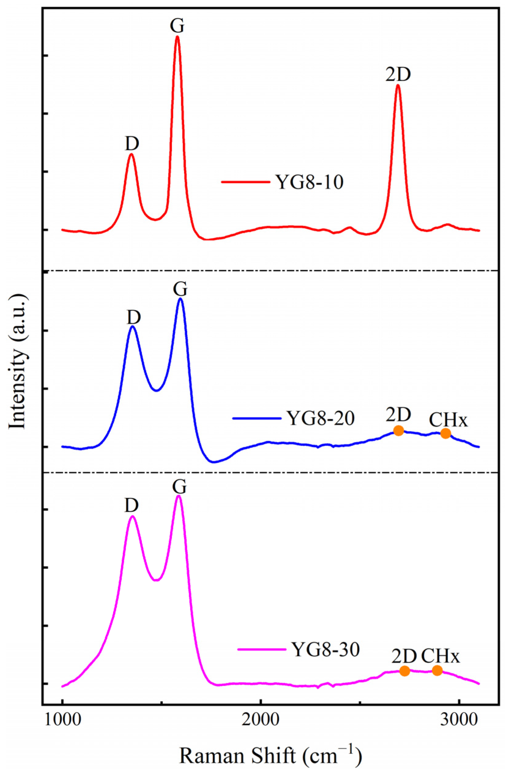
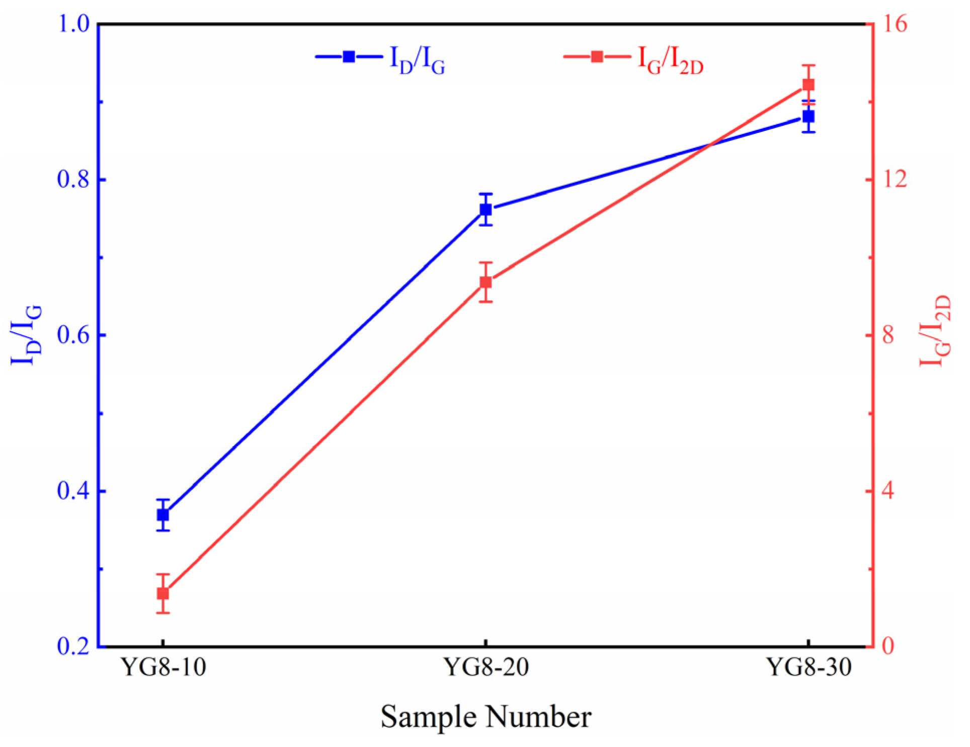
3.3. Effect of Methane Flow on Deposition of Graphene-Based Coatings

Methane flow determines the amount of carbon source supplied per unit time during the growth of graphene, so methane flow affects the number of layers and defect content of graphene coating. As a consequence, the study analyzed the influence of methane flow on graphene growth by changing the methane flow rate. Table 3 lists the specific experimental parameters.
The Raman spectrum results of the coating under three methane flows are demonstrated in Figure 7. The 2D peak of the graphene characteristic peak is pronounced, and the intensity of the D peak is faint when the methane flow rate is 10 sccm. The intensity of the 2D peak declines and the Raman distinctive peak of CHx appears with the increase of methane flow, while the D peak increases. Figure 8 illustrates the ID/IG and IG/I2D values of graphene-based coatings as a function of methane flow. Methane flow rate plays an important role in the growth of graphene. At a moderate methane flow rate, graphene with low defects and fewer layers can be formed on the surface of YG8. The number of graphene layers increases as the methane flow augments, amorphous carbon appears, and defects increase in the graphene-based coating.

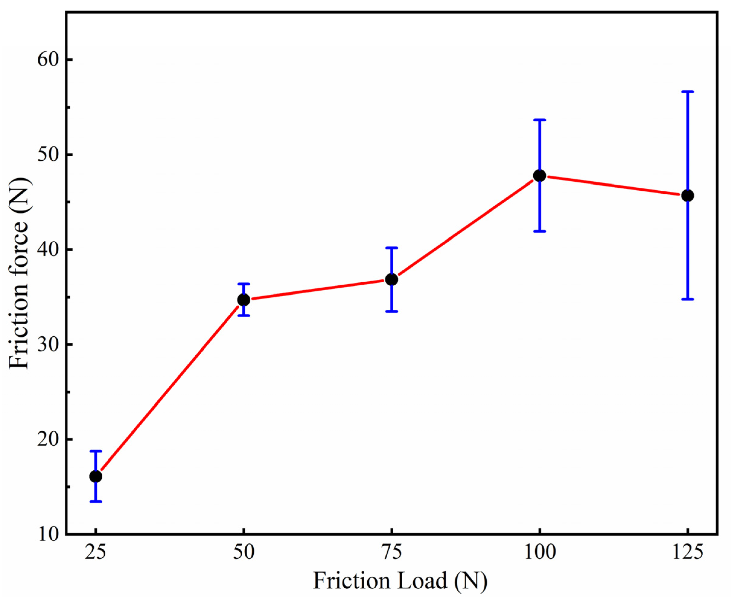
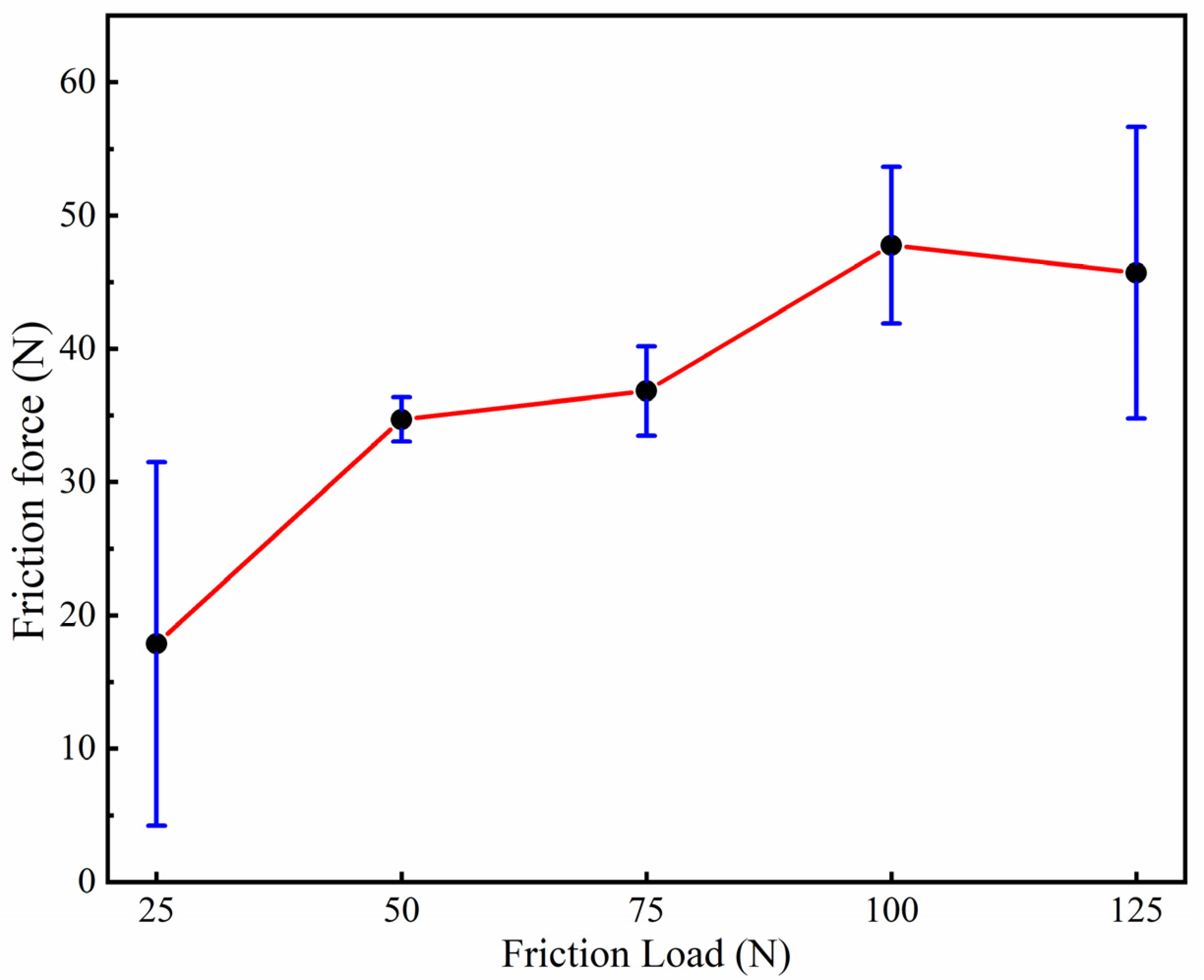
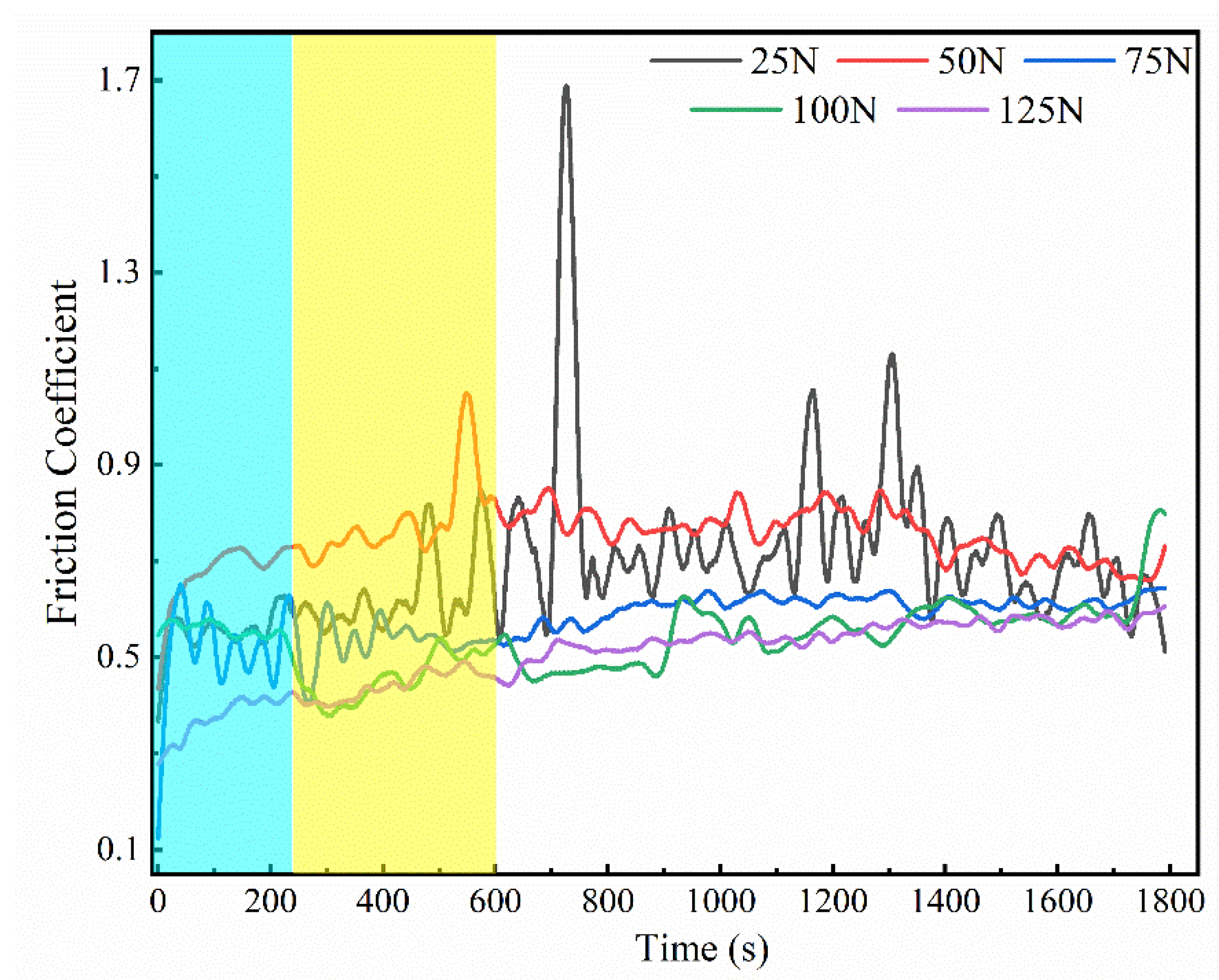
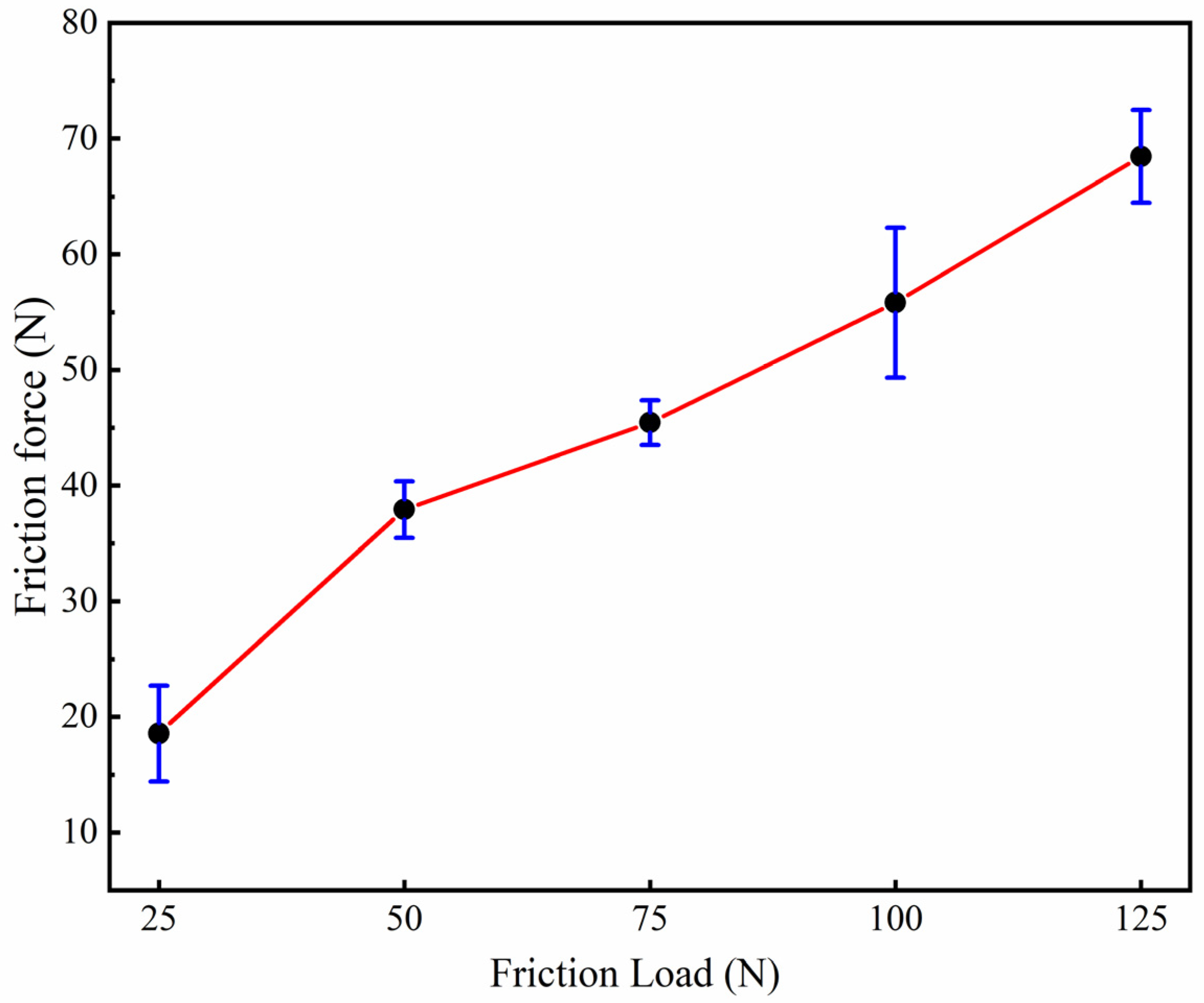
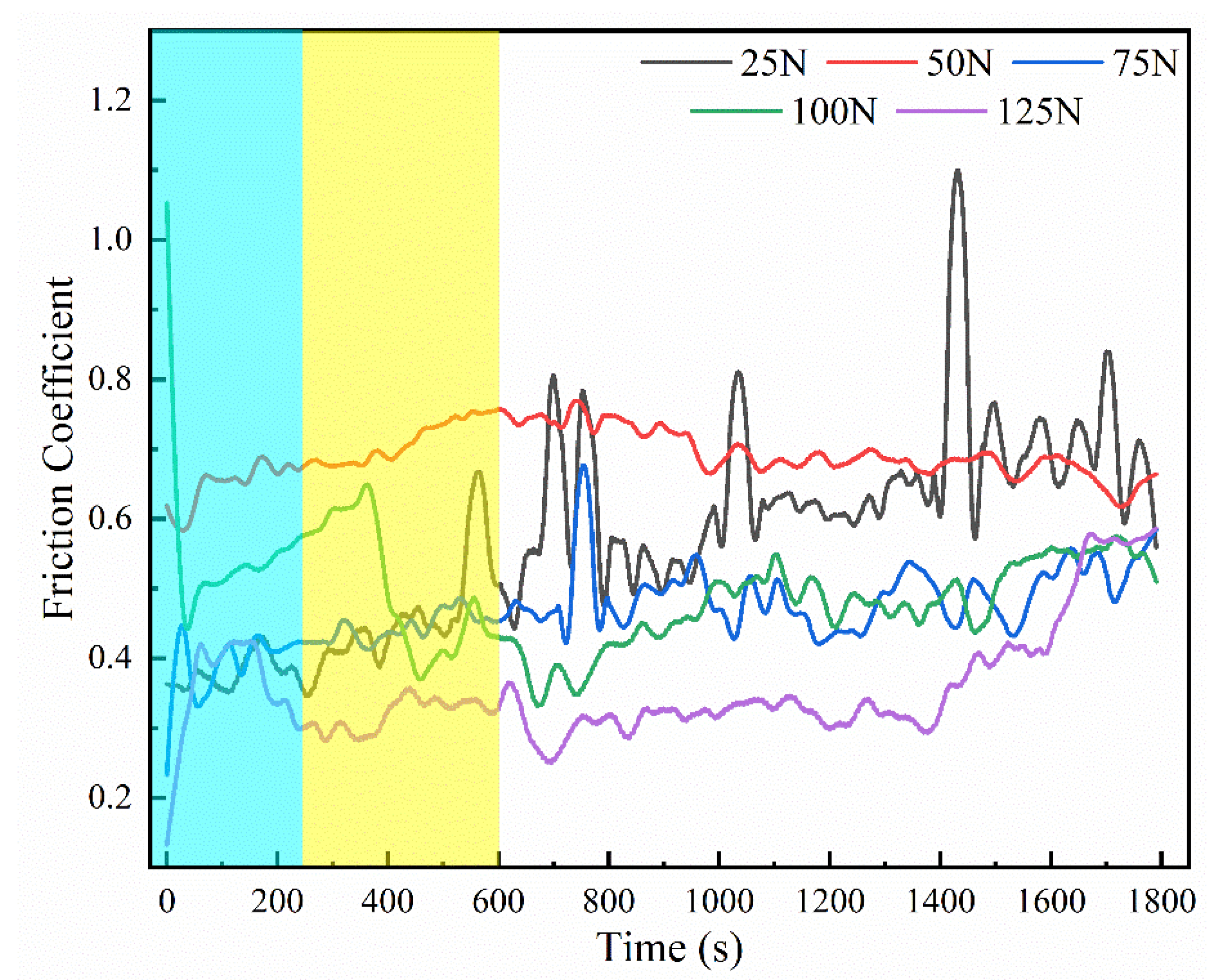
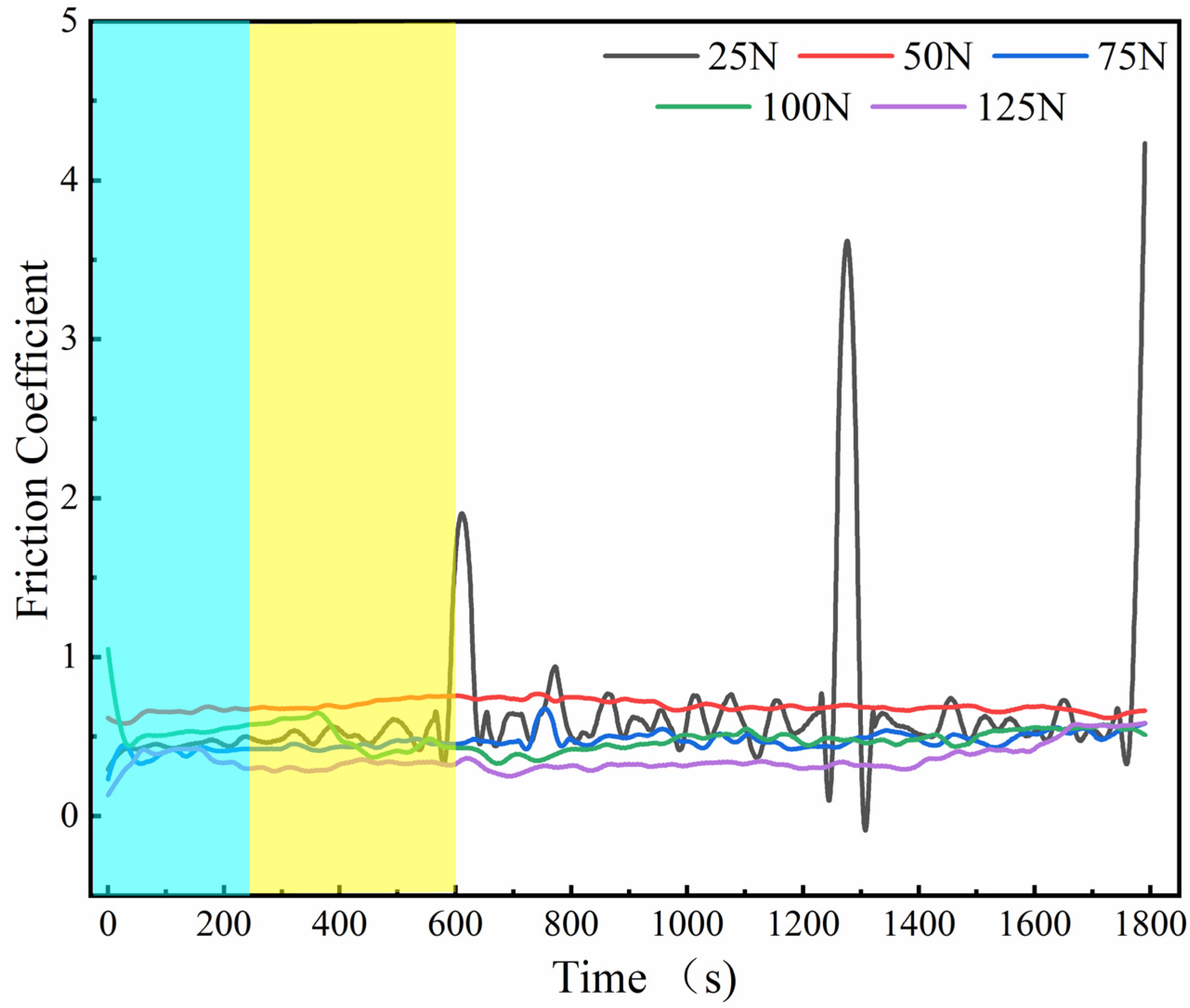
3.4. Tribological Properties of Graphene-Based Coatings

Graphene-based coatings prepared under various process parameters can be divided into two main categories: one is pure graphene coating with few layers, and the other is a dense hybrid coating of graphene and amorphous carbon, according to the research results in Section 3.1, Section 3.2 and Section 3.3. The graphene coating grown on the YG8 substrate gradually changed from a few layers of graphene coating to a mixture of graphene and amorphous carbon with the increase of methane flow, which is also the different types of graphene coating corresponding to YG8-10, YG8-20, and YG8-30 samples under the experimental parameters of the growth temperature of 1000 °C and cooling rate of 15 °C/min. Accordingly, samples YG8-10, YG8-20, and YG8-30 were selected for friction experiments to study the tribological properties of various graphene-based coatings under different loads. The specific preliminary planning is shown in Table 4 below.
YG8-10 is a graphene coating with few layers of amorphous carbon doping. Figure 9 indicates the variation of friction coefficient of YG8-10 with time under different loads. The friction coefficient fluctuates little at the initial stage of friction before 4 min (blue area in Figure 9). The friction coefficient fluctuates in different degrees between 4 and 10 min (yellow area in Figure 9), which is a transitional period. After 10 min (white area in Figure 9), the friction process tends to be steady, and the friction coefficient is comparatively stable. Figure 10 shows the curve of the mean frictional force and frictional load in the stabilized friction stage of the YG8-10 sample. As can be seen from Figure 10, with the enhancement of the friction load, the average friction force was lower as a whole.
The coating of the YG8-20 sample is a graphene-based coating mixed with graphene and amorphous carbon. Figure 11 shows the variation curve of the friction coefficient of YG8-20 over time under different loads. The law of initial friction and the transitional period is fundamentally the same as that of YG8-10. It is observed from Figure 12 that the average friction force growth trend of YG8-20 slowly slows down with the increase of the friction load, and even when the applied load is 125 N, the friction force is only 45.7 N.
The coating of sample YG8-30 is also a graphene-based coating with a blend of graphene and amorphous carbon, and the number of graphene layers is significant. Figure 13 shows the variation curve of the friction coefficient of sample YG8-30 under different loads. The rule is the same as that of YG8-10 and YG8-20. Figure 14 shows the curve of the mean value of the friction force altering the friction load in the stable friction phase of the YG8-30 sample. The growth trend of the average friction force of YG8-30 progressively slows down with the increase of the friction load, but its variation range is smaller than that of YG8-10 and YG8-20.
Figure 15 shows the surfaces of uncoated (YG8)/coated (YG8-10) carbide round rods after friction at 100 N pressure, respectively. A large number of built-up edges are formed at the edge of the friction surface of the uncoated carbide round rod (Figure 15a), causing the friction surface to undulate over 66 microns (Figure 15b). However, a small amount of built-up edges are formed on the friction surface of the coated carbide round rod (Figure 15c), and the friction surface fluctuation is about 12 microns (Figure 15d). A large number of graphene transfer films are formed by graphene-based coatings at the undulated parts of the friction surface, and these graphene transfer films act as solid lubricating films, as shown in Figure 15c.

4. Discussion

In this research, three process parameters of the graphene-based coating prepared by CVD were taken as variables to investigate their effects on the composition of the graphene-based coating. On the surface of YG8 cemented carbides, a few layers of graphene coating and a mixture of graphene and amorphous carbon can be grown. Ni, Cu, Co, and other metallic materials can all play a catalytic role in the catalytic cracking of carbon sources of hydrocarbon gases. In addition to the subtle differences in catalytic capacity between substrates, the differences in carbon solubility of numerous metal substrates at high temperature will have an important impact on the growth process and mechanism of graphene. According to the difference in the amount of carbon dispersed in the metal matrix at a high temperature, the current growth mechanisms of graphene predominantly incorporate “carburizing and carbon precipitation mechanism” and the surface diffusion growth mechanism. On the surface of nickel and copper, the mechanisms of “carburizing and carbon precipitation” and the mechanism of “surface diffusion growth” are the primary mechanisms. On the surface of cobalt, the growth mechanism of graphene is mainly surface diffusion growth, and the mechanism of “carburizing and carbon precipitation” is the secondary mechanism. The growth mechanism of graphene on the substrate surface of YG8 cemented carbides is similar to that of Co, which is dominated by surface diffusion and supplemented by carburization [35].
Diverse substrates determine the different generation mechanisms of graphene, and different carbon sources determine the minimum growth temperature required for the preparation of graphene, while the growth conditions (growth temperature, cooling rate, and carbon source content, etc.) will have a tremendous impact on the quality of graphene. The cooling rate only has an essential influence on the growth process of carburizing and carbon evolution. During cooling, the amount of carbon dissolved in the matrix decreases, and carbon atoms are precipitated from the metal due to supersaturation, and graphene is grown on the surface of the matrix. Studies indicate that excessive cooling is not conducive to the precipitation of carbon atoms and affects the growth of graphene. Hence, graphene with uniform layers and low defect density can only be grown under the premise of an appropriate cooling rate. This conclusion is the same as the research results of Liu [36] et al.
The growth temperature largely depends on the lowest decomposition temperature of the carbon source. Graphene cannot be prepared if the growth temperature is lower than the decomposition temperature of the carbon source. When the growth temperature is higher than the decomposition temperature of the carbon source, the quality (layer number and defect density) of graphene will still be affected by different temperatures. Our experimental results demonstrate that when the temperature is elevated higher than 900 °C, graphene starts to appear on the surface of YG8, and as the temperature raises, the monolayer characteristics of graphene become more obvious and the defects progressively decrease. This is similar to the growth of graphene on a Cu surface [37], which also indirectly proves that the growth of graphene on the YG8 surface contains surface diffusion at least.
Carbon source content refers to the total amount of carbon sources involved in the growth of graphene. Gaseous carbon source content is related to the growth time and gas flow rate. If the growth time is long and the gas flow rate is large, the total amount of carbon sources involved in the reaction will be more. Fewer carbon sources provide enough carbon atoms to produce graphene, which, in turn, increases the number of layers and defects.
The graphene-based coating can effectively reduce the friction of YG8/45 steel when paired with YG8 material at a friction load of 25 N~125 N, and the multilayer graphene-amorphous carbon hybrid coating has a better wear reduction effect at a large load. Graphene, as a carbon nanomaterial, is the smallest structural unit of carbonaceous solid lubricating materials (graphite and carbon nanotubes). Although there are few studies on the tribological properties of graphene under large loads, the tribological properties of graphene under tiny loads are similar to those under large loads. Kim [31] et al. not only found that the tribological performance of multilayer graphene was better than that of single-layer graphene, but also discovered that the friction interface formed a large number of graphene transfer films, which acted as a solid lubrication film.
Although graphene-based coatings were successfully prepared on the surface of YG8 cemented carbides in this survey, there are still many technological parameters that affect the preparation of graphene-based coatings, such as growth time, type of carbon source, and growth pressure. Further experiments are required to apply the coating to reduce tool wear. From the above perspective, the following work needs to be done in future research:
  • Research the effects of growth time, type of carbon source, and growth pressure on the preparation of graphene-based coatings.
  • Try to decrease the growth temperature of graphene-based coating to reduce the influence of a high temperature environment on the mechanical properties of the cemented carbide matrix.
  • Study the bonding strength between graphene-based coating and the matrix.
  • Carry out experimental research on the actual cutting performance of graphene-based coated tools.

5. Conclusions

In this paper, the effects of cooling rate, growth temperature, and methane flow on the preparation of graphene-based coatings on cemented carbide surfaces were investigated, and the effects of friction loads on the tribological properties of graphene-based coatings were experimentally studied. The following conclusions can be highlighted from the present research:
  • The pure graphene coating with fewer layers on a cemented carbide surface is the best growth condition: the growth temperature was 1000 °C, the cooling rate was 15 °C/min, and the methane flow rate was 10 sccm.
  • An increase in the flow of methane would lead to an increase in the number of graphene layers, which would generate amorphous carbon.
  • The friction coefficient of the graphene coating is inversely proportional to the applied friction load.
This research can provide theoretical and experimental support for the controllable preparation and tribological properties of graphene-based coatings on cemented carbide surfaces. Although this research has a preliminary study on the tribological properties of graphene-based coatings, there is still a lot of work to be accomplished before the application of graphene-based coatings, such as the binding strength of graphene-based coatings, long-term friction properties, and so on.

Author Contributions

Methodology and investigation: W.-B.H., K.L. and K.-P.D.; writing—original draft preparation: K.L. and K.-P.D.; conceptualization: W.-B.H., K.L. and K.-P.D.; writing—reviewing and editing: K.L. and K.-P.D.; data curation: K.L., E.-Z.R. and K.-P.D.; supervision: W.-B.H., J.M., W.-Y.M. and K.L.; software: K.-P.D. and G.-Y.Y.; visualization: W.-B.H. and X.-S.W. All authors have read and agreed to the published version of the manuscript.

Funding

This work was supported by the National Natural Science Foundation of China (Grant No. U2004169).

Institutional Review Board Statement

Not applicable.

Informed Consent Statement

Not applicable.

Data Availability Statement

The data that support the findings of this study are available from the corresponding author upon reasonable request.

Conflicts of Interest

The authors declare that they have no conflict of interest.

References

  1. Zhang, T.Y.; Long, Y.Y.; Mu, C.L.; Zhou, W.; Lian, Y.S. Performance of soft/hard composite dual-effect coated tool in dry cutting of carbon fiber–reinforced polymer. Int. J. Adv. Manuf. Technol. 2020, 109, 2814–2823. [Google Scholar] [CrossRef]
  2. Kumar, C.S.; Majumder, H.; Khan, A.; Patel, S.K. Applicability of DLC and WC/C low friction coatings on Al2O3/TiCN mixed ceramic cutting tools for dry machining of hardened 52100 steel. Ceram. Int. 2020, 46, 11889–11897. [Google Scholar] [CrossRef]
  3. Deng, Y.; Chen, W.L.; Li, B.X.; Wang, C.Y.; Kuang, T.C.; Li, Y.Q. Physical vapor deposition technology for coated cutting tools: A review. Ceram. Int. 2020, 46, 18373–18390. [Google Scholar] [CrossRef]
  4. Boing, D.; Oliveira, A.J.D.; Schroeter, R.B. Evaluation of wear mechanisms of PVD and CVD coatings deposited on cemented carbide substrates applied to hard turning. Int. J. Adv. Manuf. Technol. 2020, 106, 5441–5451. [Google Scholar] [CrossRef]
  5. Chen, J.; He, G.Y.; Han, Y.T.; Yuan, Z.W.; Li, Z.; Zhang, Z.L.; Han, X.; Yan, S.W. Structural toughness and interfacial effects of multilayer TiN erosion-resistant coatings based on high strain rate repeated impact loads. Ceram. Int. 2021, 19, 27660–27667. [Google Scholar] [CrossRef]
  6. Lin, Y.W.; Chich, P.C.; Huang, J.H. Effect of Ti interlayer thickness on mechanical properties and wear resistance of TiZrN coatings on AISI D2 steel. Surf. Coat. Technol. 2020, 394, 125690. [Google Scholar] [CrossRef]
  7. Lian, Y.S.; Long, Y.Y.; Zhao, G.L.; Mu, C.L.; Li, X.M.; Deng, J.X.; Xie, C.P. Performance of CrCN-WS2 hard/soft composite coated tools in dry cutting of titanium alloys. J. Manuf. Process. 2020, 54, 201–209. [Google Scholar] [CrossRef]
  8. Tyagi, R.; Das, A.K.; Mandal, A. Formation of superhydrophobic surface with enhanced hardness and wear resistance by electrical discharge coating process. Tribol. Int. 2021, 157, 106897. [Google Scholar] [CrossRef]
  9. Zhang, S.; Xiao, G.C.; Chen, Z.Q.; Ji, L.G.; Xu, C.H.; Yi, M.D.; Zhang, J.J.; Zhou, T.T. Mechanical properties, microstructure and crack healing ability of Al2O3/TiC/TiB2/h-BN@-Al2O3 self-lubricating ceramic tool material. Ceram. Int. 2021, 47, 14551–14560. [Google Scholar] [CrossRef]
  10. Wang, T.; Zhang, J.; Li, Y.; Gao, F.; Zhang, G.J. Self-lubricating TiN/MoN and TiAlN/MoN nano-multilayer coatings for drilling of austenitic stainless steel. Ceram. Int. 2019, 45, 24248–24253. [Google Scholar] [CrossRef]
  11. Ji, L.G.; Chen, Z.Q.; Guo, R.X.; Xu, C.H.; Guo, N.S. Preparation of nano-coating powder CaF2@-Al(OH)3 and its application in Al2O3/Ti(C,N) self-lubricating ceramic tool materials. Ceram. Int. 2020, 46, 15949–15957. [Google Scholar] [CrossRef]
  12. Liu, J.X.; Wang, X.; Liu, Y.; Liu, X.Y.; Fan, K. Bioinspired three-dimensional and multiple adsorption effects toward high lubricity of solvent-free graphene-based nanofluid. Carbon 2022, 188, 166–176. [Google Scholar] [CrossRef]
  13. Wu, H.S.; Shen, G.Z.; Li, R.X.; Zhang, L.Y.; Jie, X.H.; Liu, G. Influence of embedded reduced graphene oxide on the corrosion-wear performance of cold sprayed Zn-rGO/Al coating in NaCl solution. Surf. Coat. Technol. 2022, 429, 127856. [Google Scholar] [CrossRef]
  14. Liu, C.; Yang, X.Q.; Ma, W.; Wang, X.Z.; Jiang, H.Y.; Ren, W.C.; Sun, D.M. A silicon-graphene-silicon transistor with an improved current gain. J. Mater. Sci. Technol. 2022, 104, 127–130. [Google Scholar] [CrossRef]
  15. Zhang, Z.; Zhang, Y.; Liu, D.H.; Zhang, Y.M.; Zhao, J.Q.; Zhang, G.J. Bubble Behavior and Its Effect on Surface Integrity in Laser-Induced Plasma Micro-Machining Silicon Wafer. J. Manuf. Sci. Eng. 2022, 144, 091008. [Google Scholar] [CrossRef]
  16. Low, W.H.; Lim, S.S.; Siong, C.W.; Chia, C.H.; Khiew, P.S. One dimensional MnV2O6 nanobelts on graphene as outstanding electrode material for high energy density symmetric supercapacitor. Ceram. Int. 2021, 47, 9560–9568. [Google Scholar] [CrossRef]
  17. Ming, W.Y.; Shen, F.; Zhang, G.J.; Liu, G.D.; Du, J.G.; Chen, Z.J. Green machining: A framework for optimization of cutting parameters to minimize energy consumption and exhaust emissions during electrical discharge machining of Al 6061 and SKD 11. J. Clean. Prod. 2021, 285, 124889. [Google Scholar] [CrossRef]
  18. Mu, J.; Gao, F.J.; Cui, G.; Wang, S.; Tang, S.; Li, Z.L. A comprehensive review of anticorrosive graphene-composite coatings. Prog. Org. Coat. 2021, 157, 106321. [Google Scholar] [CrossRef]
  19. Gara, D.K.; Raghavendra, G.; Prasad, P.S.; Ojha, S. Enhanced mechanical properties of glass fibre epoxy composites by 2D exfoliated graphene oxide filler. Ceram. Int. 2021, 47, 34860–34868. [Google Scholar] [CrossRef]
  20. Ahmad, S.; Ali, S.; Salman, M.; Baluch, A.H. A comparative study on the effect of carbon-based and ceramic additives on the properties of fiber reinforced polymer matrix composites for high temperature applications. Ceram. Int. 2021, 47, 33956–33971. [Google Scholar] [CrossRef]
  21. Tseng, S.F.; Yang, Y.H. Superhydrophobic graphene/ceramic templates for the preparation of particulate drugs. Ceram. Int. 2022, 48, 2021–2030. [Google Scholar] [CrossRef]
  22. Zhang, Z.; Zhang, Y.; Ming, W.Y.; Zhang, Y.M.; Cao, C.; Zhang, G.J. A review on magnetic field assisted electrical discharge machining. J. Manuf. Process. 2021, 64, 694–722. [Google Scholar] [CrossRef]
  23. Ai, Z.S.; Feng, G.X.; Ping, Y.R.; Qin, X.; Ping, X.L.; Xun, W.Z. Self-lubrication and wear-resistance mechanism of graphene-modified coatings. Ceram. Int. 2020, 46, 15915–15924. [Google Scholar] [CrossRef]
  24. Ollik, K.; Lieder, M. Review of the application of graphene-based coatings as anticorrosion layers. Coatings 2020, 10, 883. [Google Scholar] [CrossRef]
  25. Fang, Z.; Huang, L.J.; Fu, J.J. Research Status of Graphene Polyurethane Composite Coating. Coatings 2022, 12, 264. [Google Scholar] [CrossRef]
  26. Berman, D.; Erdemir, A.; Sumant, A.V. Few layer graphene to reduce wear and friction on sliding steel surfaces. Carbon 2013, 54, 454–459. [Google Scholar] [CrossRef]
  27. Wang, X.C.; Zhao, J.; Gan, Y.L.; Tang, X.K.; Gai, S.L.; Sun, X.S. Cutting performance and wear mechanisms of the graphene-reinforced Al2O3-WC-TiC composite ceramic tool in turning hardened 40Cr steel. Ceram. Int. 2022, 48, 13695–13705. [Google Scholar] [CrossRef]
  28. Zhang, J.; Gao, X.; Xu, Q.; Ma, T.B.; Hu, Y.Z.; Luo, J.B. Atomistic insights into friction and wear mechanisms of graphene oxide. Appl. Surf. Sci. 2021, 546, 149130. [Google Scholar] [CrossRef]
  29. Singh, S.; Chen, X.C.; Zhang, C.H.; Gautam, R.K.; Tyagi, R.; Luo, J.B. Nickel-catalyzed direct growth of graphene on bearing steel (GCr15) by thermal chemical vapor deposition and its tribological behavior. Appl. Surf. Sci. 2020, 502, 144135. [Google Scholar] [CrossRef]
  30. Tsujimoto, M.; Ogata, Y.; Tachibana, M. Pit formation with graphene growth on copper foils by ethanol chemical vapor deposition. Diam. Relat. Mater. 2020, 101, 107602. [Google Scholar] [CrossRef]
  31. Kim, K.S.; Lee, H.L.; Lee, C.; Lee, S.K.; Jang, H.; Ahn, J.H.; Kim, J.H.; Lee, H.J. Chemical Vapor Deposition-Grown Graphene: The Thinnest Solid Lubricant. ACS Nano. 2011, 5, 5107–5114. [Google Scholar] [CrossRef]
  32. Jiang, X.F.; Song, J.J.; Su, Y.F.; Zhang, Y.S.; Hu, L.T. Novel Design of Copper-Graphite Self-Lubricating Composites for Reliability Improvement Based on 3D Network Structures of Copper Matrix. Tribol. Lett. 2018, 66, 143. [Google Scholar] [CrossRef]
  33. Huang, Y.C.; Shi, X.L.; Yang, K.; Liu, X.Y.; Wang, Z.H. Effects of frictional heat on the tribological properties of Ni3Al matrix self-lubricating composite containing graphene nanoplatelets under different loads. Proc. Inst. Mech. Eng. Part J J. Eng. Tribol. 2018, 232, 645–656. [Google Scholar] [CrossRef]
  34. Nguyen, V.L.; Duong, D.L.; Sang, H.L.; Avila, J.; Lee, Y.H. Layer-controlled single-crystalline graphene film with stacking order via Cu–Si alloy formation. Nat. Nanotechnol. 2020, 15, 861–867. [Google Scholar] [CrossRef] [PubMed]
  35. Liu, K.; Ren, E.Z.; Ma, J.; Cao, Y.; Du, J.G.; Ming, W.Y.; Li, X.K.; Li, B. Controllable preparation of graphene-based film deposited on cemented carbides by chemical vapor deposition. J. Mater. Sci. 2020, 55, 4251–4264. [Google Scholar] [CrossRef]
  36. Liu, W.; Chung, C.H.; Miao, C.Q.; Wang, Y.J.; Li, B.Y.; Ruan, L.Y.; Patel, K.; Park, Y.J.; Woo, J.; Xie, Y.H. Chemical vapor deposition of large area few layer graphene on Si catalyzed with nickel films. Thin Solid Films. 2010, 518, S128–S132. [Google Scholar] [CrossRef]
  37. Regmi, M.; Chisholm, M.F.; Eres, G. The effect of growth parameters on the intrinsic properties of large-area single layer graphene grown by chemical vapor deposition on Cu. Carbon 2012, 50, 134–141. [Google Scholar] [CrossRef]
Figure 1. The graphene-based coating preparation process.
Coatings 12 01385 g001
Figure 2. The pin-disc friction model.
Coatings 12 01385 g002
Figure 3. The Raman spectra at different cooling rates.
Coatings 12 01385 g003
Figure 4. The ID/IG, IG/I2D value at different cooling rates.
Coatings 12 01385 g004
Figure 5. The Raman spectra at different growth temperatures.
Coatings 12 01385 g005
Figure 6. The ID/IG, IG/I2D value at different growth temperatures.
Coatings 12 01385 g006
Figure 7. The Raman spectra at different methane flows.
Coatings 12 01385 g007
Figure 8. The ID/IG, IG/I2D value at different methane flows.
Coatings 12 01385 g008
Figure 9. The curve of the friction coefficient of sample YG8-10 over time under various loads.
Coatings 12 01385 g009
Figure 10. The curve of the mean frictional force and frictional load of sample YG8-10 (the points represent the frictional forces of the sample YG8-10 under different loads; the error value of the frictional force is shown in green; red indicates the shift curve between the load and frictional forces).
Coatings 12 01385 g010
Figure 11. The curve of the friction coefficient of sample YG8-20 over time under various loads.
Coatings 12 01385 g011
Figure 12. The curve of the mean frictional force and frictional load of sample YG8-20 (the points represent the frictional forces of the sample YG8-20 under different loads; the error value of the frictional force is shown in green; red indicates the shift curve between the load and frictional forces).
Coatings 12 01385 g012
Figure 13. The curve of the friction coefficient of sample YG8-30 over time under various loads.
Coatings 12 01385 g013
Figure 14. The curve of the mean frictional force and frictional load of sample YG8-30 (the points represent the frictional forces of the sample YG8-30 under different loads; the error value of the frictional force is shown in green; red indicates the shift curve between the load and frictional forces).
Coatings 12 01385 g014
Figure 15. The surfaces of uncoated (YG8)/coated (YG8-10) carbide round rods after friction at 100 N pressure. (a) A large number of built-up edges are formed at the edge of the friction surface of the uncoated carbide round rod; (b) the friction surface; (c) a small amount of built-up edges are formed on the friction surface of the coated carbide round rod; (d) the friction surface fluctuation.
Coatings 12 01385 g015
Table 1. The process parameters based on cooling rate.
Sample NumberMatrix ModelMethane Flow (sccm)Argon Flow (sccm)Growth Temperature (°C)Growth Time (min)Cooling
Rate (°C/min)
YG8–15YG81040010001015
YG8–25YG81040010001025
YG8–35YG81040010001035
Table 2. The process parameters based on growth temperature.
Sample NumberMatrix ModelMethane Flow (sccm)Argon Flow (sccm)Growth Temperature (°C)Growth Time (min)Cooling Rate (°C/min)
YG8–900YG8104009001015
YG8–950YG8104009501015
YG8–1000YG81040010001015
Table 3. The process parameters based on methane flow.
Sample NumberMatrix ModelMethane Flow (sccm)Argon Flow (sccm)Growth Temperature (°C)Growth Time (min)Cooling Rate (°C/min)
YG8–10YG81040010001015
YG8–20YG82040010001015
YG8–30YG83040010001015
Table 4. The process parameters of friction samples.
Sample NumberMethane Flow (sccm)Argon Flow (sccm)Growth Temperature (°C)Growth Time (min)Cooling Rate (°C/min)
YG8–101040010001015
YG8–202040010001015
YG8–303040010001015
Publisher’s Note: MDPI stays neutral with regard to jurisdictional claims in published maps and institutional affiliations.

