Abstract
The sliding bearing is an important component in machines. The characteristics of the oil film fluid of the sliding bearing is the key factor affecting lubrication, which will affect the wear and reliability of the sliding bearing. Herein, the lubricating oil of the sliding bearing is studied, the oil film flow model considering the cavitation effect is established, the pressure and temperature distribution of the oil film under different rotational speeds is explored, and its influence on oil film pressure and temperature are analyzed. Furthermore, wear tests are carried out to measure the wear amount of the bearing bush under different rotational speeds, and the influence of the fluid characteristics of the lubricating oil film on bearing wear is explored. The simulation and experimental study in this paper can provide a reference for the design of sliding bearings.
1. Introduction
Sliding bearings are widely used in machines because they work smoothly, reliably, and noiselessly. The life of sliding bearings will affect the life of the whole engine, and bearing wear is an important cause of bearing failure. The fluid characteristics of the bearing-lubricating oil film will affect the lubrication of the bearing and then influence the wear and life of the bearing [1,2,3,4,5]. In order to improve the reliability of the sliding bearings, it is necessary to fully grasp the relationship between the fluid characteristics of the bearing oil film and bearing wear, while also exploring the distribution of the lubricating oil film and the wear of the bearing under high-speed rotation. Therefore, theoretical calculations and experiments with bearings are needed as well [6,7,8].
Many scholars have researched the fluid characteristics of bearings. Li et al. [9] calculated the oil film pressure with surface roughness, and quoted the generalized Reynolds equation of the average flow model, used the oil film temperature control equation and the bearing heat transfer equation to calculate the bearing temperature and combined the Reynolds equation and temperature control equations and journal motion equations to establish a transient thermoelastic fluid lubrication analysis model for radial sliding bearings. In order to establish the calculation model of the hydrodynamic sliding bearing, Luo et al. [10] considered the conservation equation in the flow field of the sliding bearing and the boundary condition when the oil film breaks, and then applied the finite volume method to calculate the fluid characteristics. Zhang et al. [11] explained the lubricating mechanism of the hydrostatic bearing, and the lubricating oil film model was solved using FLUENT software to calculate the oil film temperature field and stress field distributions. Xie et al. [12] analyzed the relationship between the bearing and coaxial neck rotational speed based on a computational fluid dynamics (CFD) analysis of the sliding bearing oil film, establishing an oil film finite element model. The variations of oil film pressure, bearing capacity, oil film component distribution, and bearing bush stress and strain were analyzed in relation to the journal speed. Zeng et al. [13] analyzed the flow characteristics and pressure of the fluid bearings of the main pump using fluid dynamics to address bearing wear, and found that the flow acceleration in local areas caused cavitation. Gerzos et al. [14] used semi-Sommerfeld conditions as the boundary conditions to obtain the lubrication state of the non-Newtonian fluid and the static characteristics of bearings lubricated by the Newtonian fluid by solving the Navier–Stokes (N–S) basic equation. Marco Riedel et al. [15] used OpenFOAM to establish a mathematical model of the cavitation of the sliding bearing and adopted an aerodynamic method to calculate the fluid properties. Song et al. [16] solved the 3D NSE equation and analyzed the changing law of the thrust bearing lubrication performance under the influence of cavitation. They found that the oil film bearing capacity and the gas content of the oil film at high speeds were inversely proportional to each other. To reduce the influence of cavitation, increasing the oil supply pressure and decreasing the oil film thickness was suggested.
Although many scholars have worked on bearing research, most studies focus on theoretical calculations and are seldom combined with wear tests. In doing so, they leave the relationship between fluid characteristics and bearing wear unclear. In this paper, the oil film fluid characteristics of the sliding bearing are calculated through a fluid model, the pressure and temperature distribution of the oil film under different conditions is analyzed, and bearing wear tests are carried out at the same time to explore the relationship between fluid characteristics and wear. This study aims to provide guidance for the design of sliding bearings.
2. Fluid Model
A fluid model is established to present the fluid characteristic of a bearing.
The schematic diagram of hydrodynamic lubrication is shown in Figure 1. As the shaft rotates, it will bring lubricating oil into the bearing friction surface due to the viscosity of the lubricating oil. Lubricating oil was taken into the wedge clearance between the shaft and the bearing, forming a fluid dynamic pressure effect. When the pressure is balanced with the external load, a stable oil film forms between the shaft and the bearing bush, enabling hydrodynamic lubrication. The oil film supports the shaft, avoiding direct contact between the bearing and the shaft. This reduces friction and protects the surface.
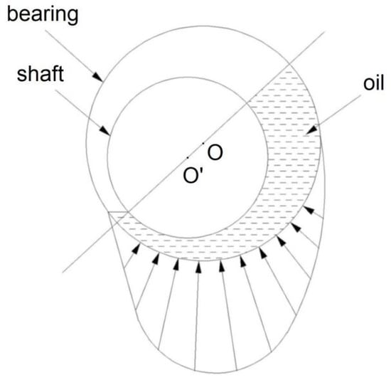
Figure 1.
Schematic diagram of hydrodynamic lubrication.
The FLUENT software (18.0) is used to calculate the fluid characteristic of the bearing. A pressure-based solver is adopted as the solver, which uses the pressure correction algorithm and solves the governing equation in scalar form. The pressure-based solver is developed from the separable solver, and solves the momentum equation, pressure correction equation, energy equation, component conservation equation, and other scalar equations in sequence.
The governing equations were as follows:
- (1)
- Continuity equation:where v is the velocity vector, ρ is the density, and t is the time.
- (2)
- Momentum equation:where p is the pressure on the fluid cell, F is the external volume force, τ is the stress tensor, and I is the unit tensor.
- (3)
- Energy conservation equation:where cρ is the specific heat capacity, T is the temperature, K is the heat transfer coefficient of the fluid, and ST is the viscous dissipation term.
The oil film model established in this paper is shown in Figure 2, and the meshing is shown in Figure 3. The hexahedral element grid is used for grid division, and the number of grids is 15,384.
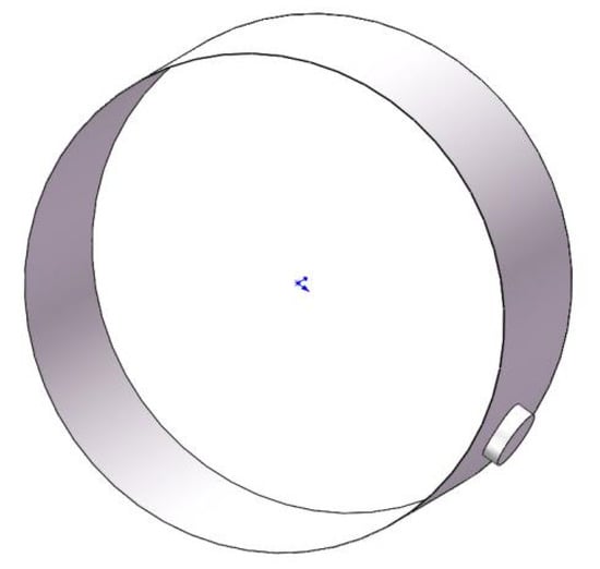
Figure 2.
Three-dimensional model of the oil film.
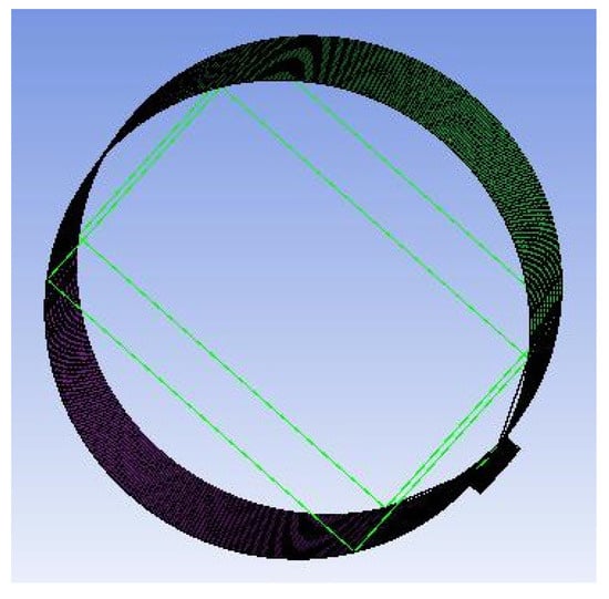
Figure 3.
Meshing of the oil film.
The boundary conditions are as follows:
- (1)
- The pressure inlet boundary condition is selected for oil film simulation, and the pressure value is the oil supply pressure:
- (2)
- The oil film simulation outlet pressure value is atmospheric pressure, set to 0:
- (3)
- Solid wall boundary conditions are used.
- (4)
- Periodic boundary conditions are used.
- (5)
- Cavitation is considered in the numerical simulation of the oil film. The calculation parameters of this model are shown in Table 1.
 Table 1. Oil film size parameters.
3. Experimental Details
3.1. Wear Test
The schematic diagram wear test device is shown in Figure 4. A motor drives the shaft to rotate, and loads are applied above the bearing seat. An oil pipe is arranged below the bearing seat for the lubricating oil supply, forming an oil film between the shaft and the bearing bush. The wear of the bearing bush under different working conditions can be measured using tests. The bearing bush before testing is shown in Figure 5. The bearing is made of a steel back, a copper alloy layer, and a lead alloy coating. The yellow part is a copper alloy, the upper part is a lead alloy coating, and the lower part is a steel back, as shown in Figure 6. The roughness of the bearing is 0.2 Ra. The load in this test is 10 MPa.
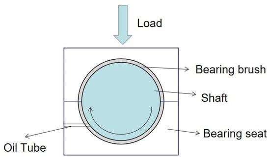
Figure 4.
Schematic diagram of the testing machine.
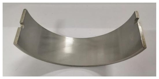
Figure 5.
Bearing bush.
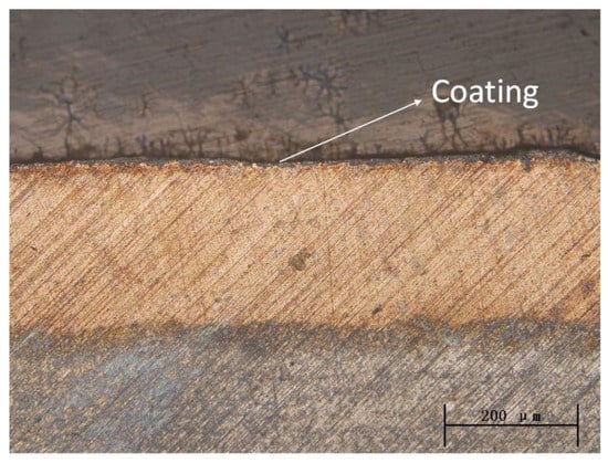
Figure 6.
Section view of bearing bush.
3.2. Detecting Instrument
The microtopography of the surface was detected using a Philips-30TMP scanning electron microscope (Philips, Amsterdam, The Netherlands), the sample was cut and polished to meet the scanning requirements of small size sample, then it was ultrasonically cleaned in gasoline and alcohol. The wear loss was weighed with a METTLER TOLEDO analytical balance (METTLER, Zurich, Switzerland), and the sample was cleaned with gasoline and alcohol before the weight measurement.
4. Results and Discussion
4.1. Oil Film Pressure
The oil film pressure distribution at different speeds (800, 900, and 1000 rpm) is shown in Figure 7. As seen in Figure 7, the stress area mainly consists of two areas. One is the wedge convergence area, which determines the bearing capacity of the oil film. The other is the divergence zone, which is the location of the natural rupture of the oil film and affects the continuity and stability of the oil film. In the wedge-shaped convergence region, the oil film pressure increases with a decreasing gap size. In the divergence zone, the oil film pressure decreases slowly with the gradual increase in the size of the oil film gap. When the oil film pressure is less than the oil film cavitation pressure, the oil film will break, and the air dissolved in the lubricating oil will be precipitated. As can be seen from the figure, the inlet pressure value, the range of the oil film bearing, and the position of the maximum oil film pressure were less influenced by rotational speed. At the same position in the bearing area, the oil film pressure increases gradually with the rotational speed, as the centrifugal force on the journal increases gradually with the rotational speed of the journal. Figure 8 shows the maximum pressure. As seen from Figure 8, the maximum pressure of the oil film at 800, 900, and 1000 rpm is 0.832, 0.939, and 1.05 MPa, respectively. When the rotational speed increases from 800 rpm to 900 rpm, the oil film pressure increases by 12.8%; when the rotational speed increases from 800 rpm to 900 rpm, the oil film pressure increases by 11.9%.
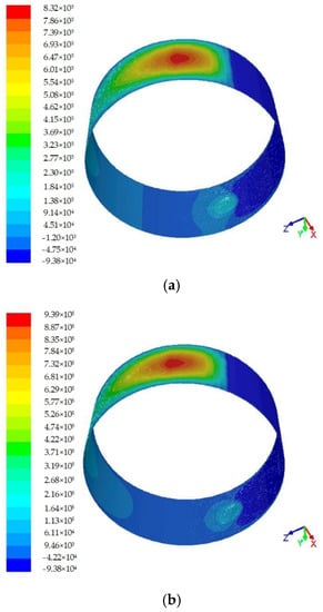
Figure 7.
Oil film pressure distribution at different speeds of (a) 800 rpm, (b) 900 rpm and (c) 1000 rpm.
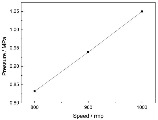
Figure 8.
Maximum oil film pressure at different speeds.
The calculation results show that the oil film pressure is large, so the fluid dynamic pressure lubrication could be formed, which separates the shaft from the bearing and avoids direct contact between the metals. Therefore, it is speculated that the wear amount of the bearing bush is very small.
4.2. Temperature Distribution of the Oil Film
The oil film temperature distribution at different speeds is shown in Figure 9. With the increase in the rotational speed, the inlet oil film temperature remains basically unchanged, and the inlet temperature is maintained at 363K, indicating that the inlet temperature has little relation to the journal rotational speed. Theoretically, the oil film temperature should increase in the wedge-shaped gap but, in fact, the temperature changes little, because the oil film temperature is mainly affected by the inlet oil temperature at this time, and the heat generated by oil friction is too small compared to the inlet temperature and can be ignored. When the oil flows through the minimum clearance, the oil film temperature begins to decline as the influence of inlet temperature begins to weaken. This temperature reduction is mainly due to the heat dissipation exchange with the external environment.
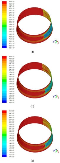
Figure 9.
Oil film temperature distribution at different speeds of (a) 800 rpm, (b) 900 rpm and (c) 1000 rpm.
4.3. Wear Weight of Bearing
After wear testing, the bearing bush was analyzed with a scanning electron microscope and weighed to observe its wear. The original surface topography of the bearing bush is shown in Figure 10a, and it can be seen here that the surface is smooth and there are many original machining marks. Figure 10b–d shows the surface topography of the bearing bush after the wear testing at 800, 900, and 1000 rpm, respectively. The worn surface looks the same as the original surface with no signs of wear. The observed oil film temperature distributions at 800, 900, and 1000 rpm are shown in Figure 11. The wear quantity of the bearing bush at each speed was 0.6 mg, 0.6 mg, and 0.5 mg, respectively, which are all below 1 mg. Considering the error caused by installation and measurement, the wear quality can be ignored. Therefore, under the tested working conditions, fluid dynamic pressure lubrication had formed between the bearing and the shaft. The dynamic pressure of the lubricating oil film separates the bearing from the shaft, and no direct metal contact occurs, meaning that essentially no wear occurs. The experimental results agree with the simulation results.
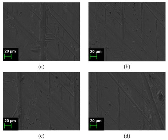
Figure 10.
Wear surface at the speed of (a) original, (b) 800 rpm, (c) 900 rpm, and (d) 1000 rpm.
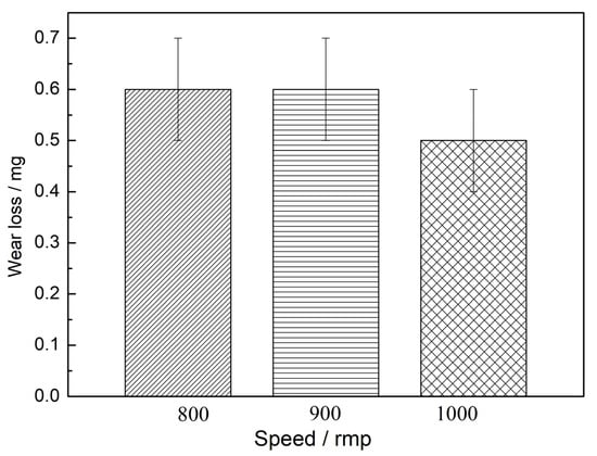
Figure 11.
Wear loss at different speeds.
5. Conclusions
- (1)
- The inlet pressure value, the range of the oil film bearing area, and the location of the maximum oil film pressure have little correlation with the journal speed. The maximum pressure of the oil film is 0.832 MPa at 800 rpm, 0.939 MPa at 900 rpm, and 1.05 MPa at 1000 rpm.
- (2)
- The inlet temperature is less affected by the journal rotational speed. As the rotational speed increases, the temperature of the inlet oil film remains basically unchanged.
- (3)
- After wear testing, the worn surface topography looks the same as the original surface with no signs of wear; the wear loss of the bearing is below 1 mg, indicating that the fluid film separates the bearing from the shaft, and almost no wear occurs.
Author Contributions
Data curation, C.C.; Methodology, K.Z.; Writing—original draft, F.D. All authors have read and agreed to the published version of the manuscript.
Funding
This research received no external funding.
Institutional Review Board Statement
Not applicable.
Informed Consent Statement
Not applicable.
Data Availability Statement
Not applicable.
Conflicts of Interest
The authors declare no conflict of interest.
References
- Brenkacz, L.; Witanowski, L.; Drosinska-Komor, M.; Szewczuk-Krypa, N. Research and applications of active bearings: A state-of-the-art review. Mech. Syst. Signal Process. 2021, 151, 107423. [Google Scholar] [CrossRef]
- Li, H.; Liu, H.; Qi, S.M.; Liu, Y. A high-speed rolling bearing test rig supported by sliding bearing. Ind. Lubr. Tribol. 2020, 72, 955–959. [Google Scholar] [CrossRef]
- Chen, G.; Qu, M.J. Modeling and analysis of fit clearance between rolling bearing outer ring and housing. J. Sound Vib. 2019, 438, 419–440. [Google Scholar] [CrossRef]
- Yang, C.Y.; Wang, S.J.; Lin, C.K.; Chung, L.L.; Liou, M.C. Analytical and experimental study on sloped sliding-type bearings. Struct. Control. Health Monit. 2021, 28, e2828. [Google Scholar] [CrossRef]
- Zhu, J.X.; Li, H.C.; Wei, S.J.; Fu, J.F.; Xu, X. An approach of simulating journal bearings-gear pump system including components’ cavitation. Simulaiton Model. Pract. Theory 2021, 108, 102236. [Google Scholar] [CrossRef]
- Chiang, H.W.D.; Kuan, C.P.; Li, H.L. Turbomolecular pump rotor-bearing system analysis and testing. J. Vac. Sci. Technol. A 2009, 27, 1196–1203. [Google Scholar] [CrossRef]
- Kosaka, R.; Nishida, M.; Maruyama, O.; Yanmbe, T.; Imachi, K.; Yamane, T. Effect of a bearing gap on hemolytic property in a hydrodynamically levitated centrifugal blood pump with a semi-open impeller. Bio-Med. Mater. Eng. 2013, 23, 37–47. [Google Scholar] [CrossRef] [PubMed]
- Lin, Q.X.; Jiang, D.H.; Deng, Z.G.; Ma, G.T.; Zheng, J.; Wang, W.J.; Shin, D.I.; Gu, X.; Lin, N.; Shao, M.L. Operation and improvement of liquid nitrogen pumps with radial high-temperature superconductor bearings. J. Low Temp. Phys. 2015, 180, 416–424. [Google Scholar] [CrossRef]
- Li, S. Transient Coupling Study of Dynamics and Tribology on Sliding Bearing. Master’s Thesis, Harbin Engineering University, Harbin, China, 2017. [Google Scholar]
- Luo, Z. Analysis of Fluid-Structure Interaction Heat Transfer of Hydrodynamic Journal Bearing Considering Thermohydrodynamic. Master’s Thesis, Xiangtan University, Xiangtan, China, 2016. [Google Scholar]
- Zhang, C. Study on the Performance of Hydrostatic Bearing Oil Clearance by Bearing Shell-Main Shaft Deformation. Master’s Thesis, Chongqing University, Chongqing, China, 2016. [Google Scholar]
- Xie, Y.; Zhang, B.; Hu, Y.M.; Ruan, D.F. Effect of journal rotation speed on characteristic of oil film and structure characteristic of bearings. Lubr. Eng. 2015, 40, 8–16. [Google Scholar] [CrossRef]
- Zeng, X.K.; Zhou, H.H.; Xiong, W.Y. CFD study on cavitation abrasion for axletree of main pump of tianwan NPP. Nucl. Power Eng. 2016, 37, 143–146. [Google Scholar]
- Gertzos, K.P.; Nikolakopoulos, P.G.; Papadopoulos, C.A. CFD analysis of journal bearing hydrodynamic lubrication by Bingham lubricant. Tribol. Int. 2008, 41, 1190–1204. [Google Scholar] [CrossRef]
- Marco, R.; Marcus, S.; Peter, R. Application of computational fluid dynamics on cavitation in journal bearings. EPJ Web Conf. 2014, 67, 02099. [Google Scholar]
- Song, Y.; Ren, X.; Gu, C.W. Experimental and numerical studies of cavitation effects in a tapered land thrust bearing. J. Tribol. 2015, 137, 011701. [Google Scholar] [CrossRef]
Publisher’s Note: MDPI stays neutral with regard to jurisdictional claims in published maps and institutional affiliations. |
© 2022 by the authors. Licensee MDPI, Basel, Switzerland. This article is an open access article distributed under the terms and conditions of the Creative Commons Attribution (CC BY) license (https://creativecommons.org/licenses/by/4.0/).