Abstract
In methods for multi-arc ion plating technology, the behavior and characteristics of the arc spot determine the physical characteristics of arc plasma and the properties of the subsequent deposited coatings. In this paper, the effect of arc currents on the hardness, friction coefficient, high temperature oxidation, and corrosion properties of the CrSiN coatings was studied. According to the XRD and SEM results, with the increase of arc currents, the coatings grew preferentially to the CrN (111) crystal direction, and the CrN (220) crystal phase appeared at high currents of 90 A. In addition, the number of large particles increased when the current exceeded 70 A. The HR-TEM results confirmed the formation of nanocomposite structure of nanocrystalline of CrN embedded into the amorphous phase of Si3N4 as explored by XRD. The maximum hardness was achieved at 3120 Hv when the coatings were deposited under currents around 70 A. However, the hardness values decreased with further increase of arc currents. From the contact of ceramic balls with the wear of coatings, the surface of coatings gradually produced friction marks, and the friction force increased from a steady friction force to a dynamic friction force. The high temperature oxidation results showed that fewer oxides were formed on the surface of the coatings when oxidized at 800 °C. It was also found that CrSiN nanocomposite coatings prepared at an arc current of 70 A had a larger corrosion potential and polarization impedance, which could effectively protect the tool matrix.
1. Introduction
CrN coatings can effectively improve work-piece processing performance and tool life due to their excellent properties such as their high hardness, wear resistance, and corrosion resistance. However, in the process of high-speed dry-cutting of difficult-to-machine materials, the temperature caused by cutting friction makes the coating easily lose its protective effect, which greatly reduces its tool life. The structure of nanocomposite coatings is mainly composed of a nanocrystalline nitride/amorphous phase system (MeSiN: nc-MeN/a-Si3N4, Me=Ti, Cr, etc.) [1,2]. Nanocrystals have a relatively high hardness, an amorphous phase with has high structural elasticity; the interface between the two phases has high cohesion energy. At the same time, the crystalline phase and amorphous phase are separated thermodynamically. Therefore, the nanocomposite coatings have the advantages of high toughness, excellent high temperature stability, thermal hardness, and high oxidation resistance [3,4,5,6].
A lot of thermal deposition methods are applied to deposit different functional coatings, such as the air plasma spraying process (APS) [7,8,9], wire arc spray (WAS) [10], IPS (induction plasma spray) [11], FWS (flame wire spray) [12], and AIPS (atmospheric induction plasma spray) [13]. Compared with the previous technologies, multi-arc ion plating is widely used for its high deposition efficiency in the preparation of tool coatings [14]. The disadvantage of this method is the generation of large particles which have adverse effects on the friction and corrosion resistance properties. When arc ion plating is applied to the target surface, there is a circle of bright arc spots on the target surface. The arc spot carries the total current of the arc discharge and is the source of electron, metal vapor, and droplet emission. Particle defects (called large particles) are generally large in size, equivalent to or even larger than the film thickness. The formation mechanism of large particles is very complex. Some studies believe that the arc spot on the cathode has a very high temperature, which causes the target to boil [15]. At this time, part of the target metal escapes in the form of vapor, and part of the target metal escapes in the form of droplets which will form large particles. Some studies believe that in very strong electric field, the force of electric field on molten metal surface is greater than its surface tension, and some metals are pulled out in the form of droplets [16].
The behavior and characteristics of arc spot determine the physical characteristics of arc plasma and the properties of subsequent deposited coatings. The control of cathode spot motion is the breakthrough and represents a key point in the development of arc ion plating technology [17]. The magnitude of the current and the arrangement of the magnetic field have an important influence on the motion and density of the arc spot. In this paper, multi-arc ion plating technology was used to prepare CrSiN coatings by changing the arc currents of CrSi targets. The hardness, friction coefficient, high temperature resistance, and corrosion resistance of the CrSiN coatings were investigated.
2. Experimental Details
2.1. Deposition Process
In this experiment, the substrate bias and deposition temperature were fixed, and the current applied to CrSi target (φ = 100 mm × 10 mm, 99.9 at.%, Cr:Si = 88:12) was taken as the only variable to study the influence of currents on coating deposition. The detailed preparation parameters are listed in Table 1. Si (111) and cemented carbide (YT15, φ = 10 mm × 3 mm) substrates were washed in anhydrous ethanol and acetone by ultrasonic cleaning machine for about 10 min. The single-crystal silicon (111) was used for XRD and TEM tests, and the WC-Co cemented carbide was used for mechanical tests. The pre-treated substrates were fixed on the matrix rotating frame with equal distance, and the rotating frame was placed at a position 300 mm away from the multi-arc targets. The vacuum chamber was heated to 300 °C and kept for 30 min, and the vacuum was pumped to less than 10−3 Pa. When Ar gas was injected, the working pressure was adjusted to 1.0 Pa, and the substrate bias was started for sputtering cleaning. For the deposition of Cr bonding layer, the pressure of Ar was adjusted to 1.0 Pa, the substrate bias was adjusted to −160 V, the duty cycle was adjusted to 80%, and the current of Cr target was controlled to 80 A. For the deposition of CrSiN layer: When N2 was introduced, the working pressure was adjusted to 1.0 Pa, the substrate bias was further reduced to −60 V, the duty cycle was adjusted to 80%, and the deposition time was 40 min.

Table 1.
Deposition parameters for CrSiN coating.
2.2. Characterization
X-ray diffraction (XRD: Bruker D8 advanced, Bruker, Karlsruhe, Germany) was used to detect the crystalline phase of the coatings. The surface and cross-sectional morphology of the coatings were observed by scanning electron microscopy (SEM:JSM-7610F, JEOL, Tokyo, Japan), and the element content was obtained by energy dispersive spectrometer (EDS:NORAN System 7, Thermo Fisher Inc, Waltham, MA, USA). The microstructure of the Cr–Si–N nanocomposite coatings were investigated by transmission electron microscopy (TEM: JEOL JEM 2010F, JEOL, Tokyo, Japan) working at 200 kV. The hardness value was measured by digital micro-hardness tester (Shanghai Taiming Optical Instrument Co., LTD, Shanghai, China) under 200 g loading force. The tribological behavior was evaluated on a CFT-1 ball-on-disk tester (Huahui Instrument Company, Lanzhou, China), where a rigid Si3N4 ball at a diameter of 3 mm as the mating materials slide in air at room temperature with a relative humidity of 60% was used. The weights or variable loading mechanism were applied on the grinding balls, the material sample was fixed on the test stand, and the friction pairs could realize the reciprocating uniform linear motion with fixed speed and frequency under dynamic loading or fixed-loaded. The friction coefficient curve under the specific conditions (varied loads and speeds) were obtained by computing the friction force signal collected by the sensor. During the test, an average sliding speed of the ball was set at 0.02 m/s under 100 g loading force using 1000 g sensor. The high-temperature vacuum tube furnace (GXL 1600X, Tianjin Zhonghuan Electric Furnace Co., LTD, Tianjin, China) was used for high-temperature oxidation experiment. The heating rate of the high temperature process was 5 °C/min and kept for 2 h. The corrosion resistance of the coatings was characterized by CS3500 electrochemical workstation (Shanghai Chenhua Instrument Co., LTD, Shanghai, China) in a 3.5% NaCl solution with a scanning rate of 0.5 mV/min.
3. Results and Discussion
3.1. Structure of the Coatings
Figure 1 shows the variation of element content in CrSiN coatings prepared under different CrSi arc currents. The ratio of Cr and Si is about 8:1, which is close to the ratio of Cr and Si in the targets. With the increase of arc currents, the content of the element does not change significantly. The content of the N element is less than 40%, which may be due to the fact that the metal evaporated from the arc target is deposited directly into the substrate without ionization, resulting in a high content of Cr element in the coatings. Another reason for the low Si content can be attributed to the higher affinity potential between N and Cr.
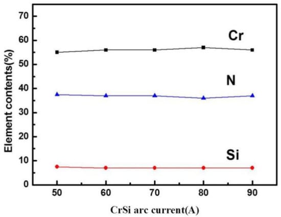
Figure 1.
Elemental content of CrSiN coatings deposited under different CrSi arc currents.
Figure 2 shows the XRD spectra of CrSiN coatings prepared under different CrSi arc currents. It can be clearly seen from the figure that with the increase of arc currents, the CrN (200) peak always exists in the coatings [18]. In addition, with the increase of current to 70 A, the (111) peak of CrN increases gradually. However, the (111) peak tends to decrease slightly as the arc current continues to increase, which may be due to the enhancement of substrate bombardment energy by high valence metal ions.
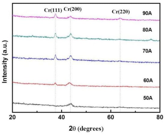
Figure 2.
XRD patterns of CrSiN coatings deposited under different CrSi arc currents.
Figure 3 shows the surface morphology of CrSiN coatings deposited under different CrSi arc target currents. With the increase of the current to 70 A, the particle size on the surface of the coatings decreases gradually. However, when the currents are further increased, the surface particle size begins to increase. The main reason is that when the current is less than 70 A, the gas ionization rate increases with the increase of currents, and the particle size of the coating is refined with the increase of ionization rate. When the current continues to increase, the number of large droplets evaporated increases, which makes coarsening of the coatings. In addition, it can be seen from Figure 3f that the coating prepared at 70 A contains only Cr, Si, and N elements.
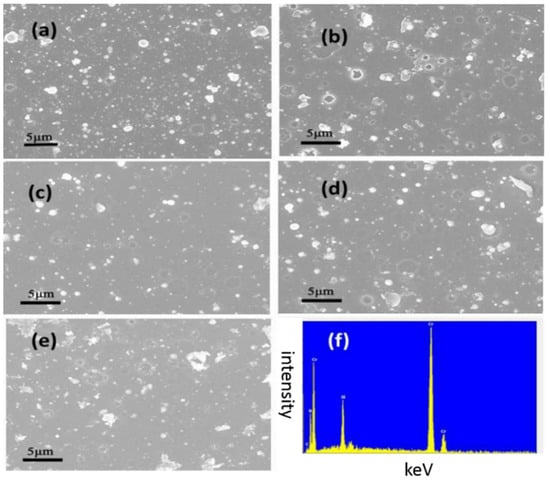
Figure 3.
Surface morphology and energy spectrum of CrSiN coatings deposited under different arc currents. (a) 50 A, (b) 60 A, (c) 70 A, (d) 80 A, and (e) 90 A. (f) EDS images of coatings prepared at 70 A.
Figure 4 shows the cross-sectional morphology of CrSiN coatings prepared under different CrSi arc currents. The coating deposited at 70 A current has the best compactness, while the coating deposited at low current has relatively loose structure due to the relatively low plasma concentration which leads to insufficient energy for particles deposition. When the arc currents are increased to 80 A, large droplets and pinhole bundles on the surface of the coatings are increased. Figure 4f shows the line sweep spectrum of the coatings prepared at currents of 70 A. It can be found that the distribution of Cr and Si elements in the coating is relatively uniform.
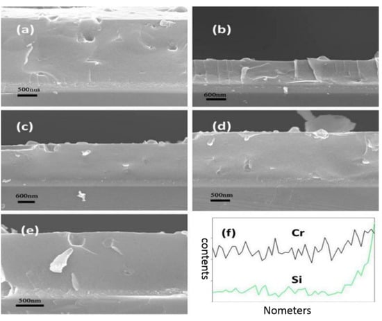
Figure 4.
Cross-sectional image and line sweep spectrum of CrSiN coatings deposited under different currents. (a) 50 A, (b) 60 A, (c) 70 A, (d) 80 A, and (e) 90 A. (f) Line sweep spectrum of coatings prepared at 70 A.
To investigate the structural details of the CrSiN coatings, TEM analysis was performed as shown in Figure 5a. It can be clearly seen that nanocrystallite with a grain size of 20–50 nm is embedded into the amorphous matrix. Figure 5b shows selected-area diffraction patterns (SAED) of CrSiN coatings deposited under arc currents of 70 A. Obviously, relatively clear ring patterns with sharp diffraction spots from B1-type CrN with diffraction reflections of (111), (200), and (220) are observed. Figure 5c shows the high resolution TEM images of the CrSiN coatings. CrN nanocrystal with grain sizes of about 20 nm is clearly visible and embedded in amorphous matrix. The fast Fourier transform image (FFT) was calculated for the areas marked as “A” in Figure 5c, suggesting a more amorphous character of the silicon-rich area compared with areas of the sample with less Si.
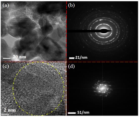
Figure 5.
TEM (a), SAED pattern (b), HR-TEM (c), and corresponding FFT (d) images of CrSiN coatings deposited under arc currents of 70 A.
3.2. Mechanical Properties
Figure 6 shows the hardness values of the coatings prepared under different arc currents. Each sample was tested 5 times and the average value was taken and the variance was calculated. The hardness increases with the increase of arc currents, and reaches a maximum value of about 3120 Hv at 70 A. However, as the current continues to increase, the hardness tends to decrease. The hardness of the CrSiN coatings prepared in this experiment does not reach the super-hard level of 4000 Hv which may be related to the lower deposition temperature and lower ion bombardment energy [19,20,21].
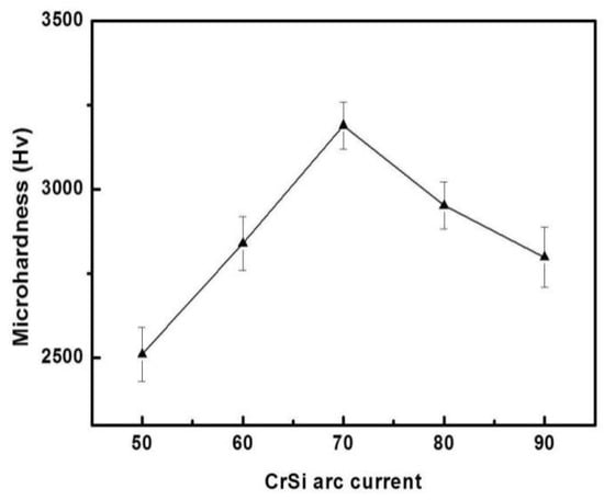
Figure 6.
Hardness properties of CrSiN coatings deposited under different arc currents.
Figure 7 shows the friction coefficient of CrSiN coatings deposited under different arc currents. With the increase of time, the friction coefficients of all CrSiN coatings increase dynamically. From the contact of ceramic balls to the wear of coatings, the surface of coatings gradually produces friction marks, and the friction force increases from steady friction force to dynamic friction force. In addition, with the increase of friction time, the friction coefficient of the coating prepared at 70 A did not increase significantly, remaining between 0.35 and 0.45. The SEM and wear trace images also prove that the coatings deposited under this parameter have part of the adhesive friction material and a rough and abrasive surface. It was revealed that the fluctuation of the friction coefficient at lower rotating speed was much larger than that at higher speed, possibly due to the surface roughness and the formation of oxide layer during sliding-contact test of the coatings. In addition, the few surface droplets and defects observed in SEM images indicated that the rough and abrasive surface of the coatings can effectively reduce the mechanical wear of sliding. It is worth noting that the friction coefficient of the coatings prepared at 50 A increased greatly to 0.6 in a short time. This was mainly due to the low compactness of the coatings prepared under 50 A, which can easily be worn by a ceramic ball [22,23,24].
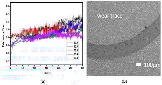
Figure 7.
Friction coefficient (a) and wear trace (b) of CrSiN coatings deposited under different arc currents.
3.3. High Temperature Resistance Properties
In order to study the high temperature oxidation resistance properties of coatings, CrSiN coatings prepared under arc currents of 70 A were heated to 800 and 900 °C, respectively, at a heating rate of 5 °C/min. Figure 8a shows that the surface of the coatings are not completely oxidized when the oxidation temperature is 800 °C. However, as can be seen from Figure 8c, the surface has been completely oxidized into large particles of oxide when the oxidation temperature is 900 °C. In addition, it can be seen from Figure 8b that although the surface of coatings is oxidized at 800 °C, it can still maintain its integrity. However, when the temperature is 900 °C, the coating has broken and peeled off and only large particles of oxide can be observed (that is, the CrSiN coating loses its protective effect).
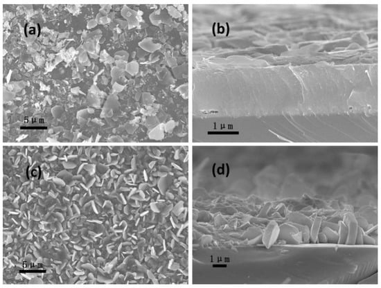
Figure 8.
Surface (a,c) and cross-sectional (b,d) morphology of CrSiN coatings deposited at arc currents of 70 A and oxidized at 800 °C (a,b), and 900 °C (c,d).
Figure 9 shows XRD spectra of CrSiN coatings prepared at arc currents of 70 A before and after oxidation. It can be seen from the figure that the CrN (111) phase disappears while the CrN (200) crystal plane still exists when the oxidation temperature is 800 °C. However, as the temperature is increased to 900 °C, all the CrN diffraction peaks disappear and only Cr2O3 oxidation peaks exist. Element diffusion and oxidation may occur at the same time in the coatings. The oxygen gas in the air diffuses into the coatings while the Cr diffuses outward. Chemical reactions may occur as follows:
2CrN + 1.5O2 = Cr2O3 + N2
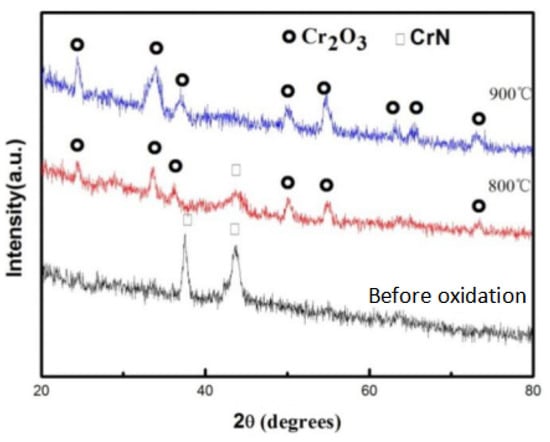
Figure 9.
XRD patterns of CrSiN coatings before and after oxidation.
According to the chemical reaction equation, the N element of the coating is gradually replaced by O, which leads to the gradual loss of protective effect of the coatings with the increase of temperature [25,26,27,28].
3.4. Corrosion Resistance Properties
Figure 10 shows the polarization curves of cemented carbide and CrSiN coatings deposited under the currents of 70 A. The potential correction of the coatings deposited under current of the 70 A is much smaller than that of cemented carbide. The curves in the figure can also prove that the CrSiN nanocomposite coatings have better corrosion resistance properties.
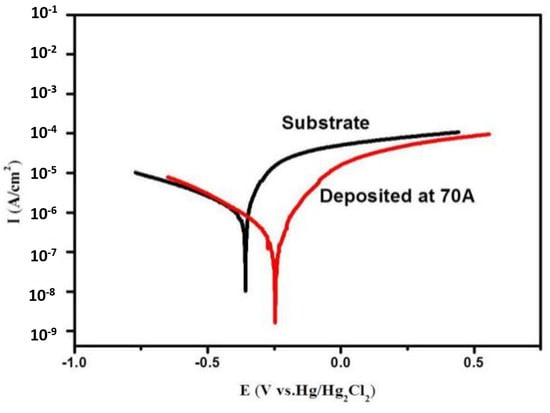
Figure 10.
Polarization curves of cemented carbide and CrSiN coatings deposited at 70 A.
Table 2 shows the fitting parameters of polarization curves shown in Figure 10. The corrosion potential of the CrSiN coatings is 0.2150 V higher than that of cemented carbide. At the same time, the current density of the coatings decreases from 0.34 to 2.7 μA/cm2 relative to cemented carbide. As a comparison, polarization impedance significant increased from 13.01 kΩ·cm2 of cemented carbide to 124.97 kΩ·cm2 of the coatings. These results show that CrSiN coatings can effectively improve the corrosion resistance of cutting tools and prolong their service life.
Table 2.
Fitting parameters from polarization curves shown in Figure 10.
4. Conclusions
Multi-arc ion plating deposition technology was used to prepare CrSiN coatings by changing the arc currents of the CrSi targets. With an increase of the arc currents, the CrSiN coating grew to the CrN (111) crystal phase, and the CrN (220) crystal phase appeared at a high current of 90 A. From high resolution TEM results, CrN nanocrystals with grain sizes of about 20 nm were clearly visible and embedded in the amorphous matrix. The maximum hardness was achieved at 3120 Hv when the coatings deposited under currents of 70 A. with the increase of friction time, the friction coefficient of the coating prepared at 70 A did not increase significantly, remaining between 0.35 and 0.45. Oxidation results show that the surface of the CrSiN coatings are not completely oxidized when the oxidation temperature is 800 °C. However, the surface has been completely oxidized into large oxide particles when the oxidation temperature is 900 °C. The polarization impedance significant increased from 13.01 kΩ·cm2 of cemented carbide to 124.97 kΩ·cm2 of the coatings. CrSiN nanocomposite coatings have high corrosion potential, low corrosion current, and high polarization impedance.
Author Contributions
Writing—original draft preparation, Y.X.; writing—review and editing, C.Z. All authors have read and agreed to the published version of the manuscript.
Funding
This work was supported by Innovation team project of Guangdong Universities (advanced PVD coating and metal surface modification technology innovation team), Special fund for science and technology innovation strategy of Guangdong Province (2020A0505100059), and Natural Science Foundation of Guangdong Province (2021A1515011928).
Institutional Review Board Statement
Not applicable.
Informed Consent Statement
Not applicable.
Data Availability Statement
Data available in a publicly accessible repository.
Conflicts of Interest
The authors declare no conflict of interest.
References
- Tao, H.; Tsai, M.T.; Chen, H.W.; Huang, J.C.; Duh, J.G. Improving high temperature tribological characteristics on nanocomposite CrAlSiN coating by Mo doping. Surf. Coat. Technol. 2018, 349, 752–756. [Google Scholar] [CrossRef]
- Tian, C.; Wang, Z.; Zou, C.; Tang, X.; Xie, X.; Li, S.; Liang, F.; Li, Z.; Liu, Y.; Su, F. Ternary and quarternary TiBN and TiBCN nanocomposite coatings deposited by arc ion plating. Surf. Coat. Technol. 2019, 359, 445–450. [Google Scholar] [CrossRef]
- Postolnyi, B.; Beresnev, V.; Abadias, G.; Bondar, O.; Rebouta, L.; de Araújo, J.P.E.; Pogrebnjak, A. Multilayer design of CrN/MoN protective coatings for enhanced hardness and toughness. J. Alloys Compd. 2017, 725, 1188–1198. [Google Scholar] [CrossRef] [Green Version]
- Postolnyi, B.; Beresnev, V.; Abadias, G.; Bondar, O.; Rebouta, L.; de Araújo, J.P.E.; Pogrebnjak, A. Residual stress, mechanical and microstructure properties of multilayer Mo2N/CrN coating produced by R.F Magnetron discharge. Appl. Surf. Sci. 2017, 395, 117–121. [Google Scholar]
- Tian, C.; Han, B.; Zou, C.; Xie, X.; Li, S.; Liang, F.; Tang, X.; Wang, Z.; Pelenovich, V.; Zeng, X.; et al. Synthesis of monolayer MoNx and nanomultilayer CrN/Mo2N coatings using arc ion plating. Surf. Coat. Technol. 2019, 370, 125–129. [Google Scholar] [CrossRef]
- Mikula, M.; Grančič, B.; Drienovský, M.; Satrapinskyy, L.; Roch, T.; Hájovská, Z.; Gregor, M.; Plecenik, T.; Čička, R.; Kúš, P. Thermal stability and high-temperature oxidation behavior of Si–Cr–N coatings with high content of silicon. Surf. Coat. Technol. 2013, 232, 349–356. [Google Scholar] [CrossRef]
- Berger, L.-M.; Sempf, K.; Sohn, Y.J.; Vaßen, R. Influence of feedstock powder modification by heat treatments on the properties of APS-sprayed Al2O3-40% TiO2 coatings. J. Therm. Spray Technol. 2018, 27, 654–666. [Google Scholar] [CrossRef]
- Basha, G.M.T.; Srikanth, A.; Venkateshwarlu, B. A critical review on nano structured coatings for alumina-titania (Al2O3–TiO2) deposited by air plasma spraying process (APS). Mater. Today Proc. 2020, 22, 1554–1562. [Google Scholar]
- Paleu, C.C.; Munteanu, C.; Istrate, B.; Bhaumik, S.; Vizureanu, P.; Bălţatu, M.S.; Paleu, V. Microstructural analysis and tribological behavior of AMDRY 1371 (Mo–NiCrFeBSiC) atmospheric plasma spray deposited, Thin Coatings. Coatings 2020, 10, 1186. [Google Scholar] [CrossRef]
- Yao, H.; Zhou, Z.; Xue, Y.; Zhou, Z.; Tan, Z.; He, D.; Wang, B.; Wang, L. Microstructure and thermal conductivity of wire-arc sprayed FeCrNbBSiC amorphous coating. J. Alloy. Compd. 2019, 788, 514–521. [Google Scholar] [CrossRef]
- Boulos, M.I. RF induction plasma spraying: State-of-the-art review. J. Therm. Spray Technol. 1992, 1, 33–40. [Google Scholar] [CrossRef]
- Junior, P.R.C.A.; Pukasiewicz, A.G.M. Evaluation of microstructure, mechanical and tribological properties of a Babbitt alloy deposited by arc and flame spray processes. Tribol. Int. 2018, 131, 148–157. [Google Scholar] [CrossRef]
- Nutsch, G. Atmospheric Induction Plasma Spraying. High Temp. Mater. Process. Int. Q. High-Technol. Plasma Process. 2011, 15, 61–74. [Google Scholar] [CrossRef]
- Yan, P.; Deng, J.X.; Lian, Y.S.; Zhao, J.; Chen, Z.; Ai, X. Effect of depositing parameters on microstructures and properties of multi arc ion plating ZrTiN films. Surf. Eng. 2012, 28, 17–23. [Google Scholar] [CrossRef]
- Hiroyuki, H.; Ayako, K.; Tetsuya, S. Ti1−xAlxN, Ti1−xZrxN and Ti1−xCrxN films synthesized by the AIP method. Surf. Coat. Technol. 2000, 132, 76–79. [Google Scholar]
- Hiroyuki, H.; Masahiro, K.; Tetsuya, S. Effects of Al contents on microstructures of Cr1-xAlxN and Zr1−xAlxN films synthesized by cathodic arc method. Surf. Coat. Technol. 2005, 200, 2409–2413. [Google Scholar]
- Anders, A. A review comparing cathodic arcs and high power impulse magnetron sputtering (HiPIMS). Surf. Coat. Technol. 2014, 257, 308–325. [Google Scholar] [CrossRef] [Green Version]
- Wang, Q.; Park, I.W.; Kim, K. Influence of N2 gas pressure and negative bias voltage on the microstructure and properties of Cr-Si-N films by a hybrid coating system. J. Vac. Sci. Technol. A Vac. Surf. Film. 2008, 26, 1188–1194. [Google Scholar] [CrossRef]
- Veprek, S. Conventional and new approaches towards the design of novel super-hard materials. Surf. Coat. Technol. 1997, 97, 15–22. [Google Scholar] [CrossRef]
- Kim, K.H.; Park, B.H. Mechanical properties and oxidation behavior of Ti–Si–N films prepared by plasma assisted CVD. Adv. Mater. 1999, 11, 275–279. [Google Scholar] [CrossRef]
- Diserens, M.; Patscheider, J.; Lévy, F. Improving the properties of titanium nitride by incorporation of silicon. Surf. Coat. Technol. 1998, 108, 241–246. [Google Scholar] [CrossRef]
- Hu, X.P.; Han, Z.H.; Li, G.Y. Microstructure and properties of Ti–Si–N nanocomposite films. J. Vac. Sci. Technol. A Vac. Surf. Film. 2002, 20, 1921–1926. [Google Scholar] [CrossRef]
- Barshilia, H.C.; Deepthi, B.; Rajamk, S. Deposition and characterization of CrN/Si3N4 and CrAlN/Si3N4 Nanocomposite coatings prepared using reactive DC unbalanced magnetron sputtering. Surf. Coat. Technol. 2007, 20, 9468–9475. [Google Scholar] [CrossRef]
- Wang, Q.M.; Kim, K.H. Microstructural control of Cr–Si–N Films by a Hybrid arc ion plating and magnetron sputtering process. Acta Mater. 2009, 57, 4974–4987. [Google Scholar] [CrossRef]
- Martinez, E.; Sanjinés, R.; Banakh, O.; Lévy, F. Electrical, optical and mechanical properties of sputtered CrNy and Cr1−xSixN1.02 thin films. Thin Solid Film. 2004, 447, 332–336. [Google Scholar] [CrossRef]
- Musil, J.; Jirout, M. Toughness of hard nanostructured ceramic thin films. Surf. Coat. Technol. 2007, 201, 5148–5152. [Google Scholar] [CrossRef]
- Huang, F.; Ge, F.F.; Zhu, P. Superhard V–Si–N Coatings (>50 GPa) with the Cell-like Nanostructure Prepared by Magnetron Sputtering. Surf. Coat. Technol. 2013, 232, 600–605. [Google Scholar] [CrossRef]
- Veprek, S.; Reiprich, S. A concept for the design of novel superhard coatings. Thin Solid Film. 1995, 268, 64–71. [Google Scholar] [CrossRef]
Publisher’s Note: MDPI stays neutral with regard to jurisdictional claims in published maps and institutional affiliations. |
© 2021 by the authors. Licensee MDPI, Basel, Switzerland. This article is an open access article distributed under the terms and conditions of the Creative Commons Attribution (CC BY) license (https://creativecommons.org/licenses/by/4.0/).