Article

Electroless Ni–P Plating on Mullite Powders and Study of the Mechanical Properties of Its Plasma-Sprayed Coating

1
State Key Laboratory of Advanced Processing and Recycling of Nonferrous Metals, Lanzhou University of Technology, Lanzhou 730050, China
2
School of Materials Science and Engineering, Lanzhou University of Technology, Lanzhou 730050, China
*
Author to whom correspondence should be addressed.
Coatings 2022, 12(1), 18; https://doi.org/10.3390/coatings12010018
Submission received: 24 November 2021 / Revised: 13 December 2021 / Accepted: 18 December 2021 / Published: 24 December 2021
(This article belongs to the Topic Inorganic Thin Film Materials)

Abstract

:
To effectively improve the properties of a mullite coating and its interfacial bonding with the substrate, a Ni–P layer is deposited on the surface of mullite powders by electroless plating. The original mullite powders and coated mullite powders are then deposited onto stainless-steel substrates by plasma spraying. The growth mechanism of the Ni–P layer during the plating, the microstructures of the coated powders and mullite coating and the properties of the mullite coatings are characterized and analyzed. The results indicate that the Ni–P layer on the surface of the mullite powder has cell structures with a dense uniform distribution and grows in layers on the surface of the mullite powder. The crystallization behavior of Ni-P amorphous layer is induced by heat treatment. Compared to the original mullite coating, the coating prepared by the coated mullite powders has better manufacturability, stronger adhesion to the substrate, lower porosity (7.40%, 65% of that of the original coating), higher hardness (500.1 HV, 1.2 times that of the original coating), and better thermal cycle resistance (two times that of the original coating). The method of preparation of high-temperature thermal barrier coatings with coated mullite powders has a high application value.

Graphical Abstract

1. Introduction

High-temperature components used in modern aerospace applications, aircraft manufacturing, and internal combustion engines usually bear high thermomechanical loads. To improve the properties and service lives of high-temperature components, thermal barrier coatings (TBCs) are often fabricated on the surface of the metallic substrate [1,2,3,4]. Generally, the methods for the preparation of TBCs include laser cladding, electron beam physical vapor deposition, and plasma spraying [5,6,7,8]. Among them, plasma spraying has a high commercial application value owing to its high deposition rate, low economic cost, and high coating speed.
Among the various thermal barrier materials, mullite is often used as a material for TBCs of diesel engines owing to its low thermal conductivity, high-temperature resistance, creep resistance, and chemical stability [9,10]. However, there is a large coefficient of thermal expansion (CTE) mismatch between mullite and metallic substrates. Thus, the thermal stress accumulation between the mullite coating and metallic substrate at high temperatures (around 1000 °C) can peel off the coating. In addition, cracks occur during recrystallization of mullite at high temperatures, which hinders the application of mullite in TBC [11]. In recent years, some researchers used the method of designing gradient coating and introducing a secondary phase to solve the above problems [12,13,14,15]. Zhang et al. [16] prepared a functionally graded environmental barrier coating containing mullite on a SiCf/SiC composite by plasma spraying–physical vapor deposition and studied the thermomechanical properties of the coating. Vakilifard et al. [17] prepared two-layer functionally graded ZrO2/NiCrAlY coatings on an Inconel 738LC alloy substrate by atmospheric plasma spraying (APS) and evaluated their corrosion behaviors in a molten salt corrosion environment. Li et al. [11] used APS to prepare a functional gradient mullite coating on an Inconel 718 alloy substrate and introduced ZrO2 secondary phase to study its thermomechanical properties and thermal cycle resistance. However, owing to the intrinsic brittleness of mullite and its low interface bonding with the metallic substrate, the coating tends to crack and peel off in a thermal shock environment. Electroless plating is expected to be an effective method to enhance the interfacial bonding between mullite and metallic substrate owing to its good uniform plating ability and high bonding ability between the coated powders and metallic substrates [18,19,20,21]. However, only a few studies on electroless plating of mullite powders have been carried out.
In this study, a Ni–P layer was coated on the surface of the mullite powder by electroless plating to improve the toughness and CTE of the mullite powder. Then the original mullite powders and coated mullite powders were used to fabricate coatings on a pretreated 304 stainless-steel substrate by plasma spraying. Subsequently, the growth mechanism of the Ni–P layer on the mullite powder surface was studied. The microstructures, phase constituents, hardnesses, porosities, thermal cycle behaviors, and thermal barrier properties of the two coatings were compared and analyzed.

2. Experimental Methods

2.1. Materials

Mullite (3Al2O3·2SiO2; Zhengdeng refratory Co., Ltd., Zhengzhou, China) powders with average particle sizes of 30–60 μm were used as raw powders for the deposition of the Ni–P layer. In the electroless plating, sodium hydroxide (NaOH), hydrochloric acid (HCl), hydrofluoric acid (HF), stannous chloride (SnCl2), nickel sulfate hexahydrate (NiSO4·6H2O), sodium hypophosphite (NaH2PO2·H2O), sodium citrate (Na3C6H5O7·2H2O), and ammonium chloride (NH4Cl) analytical reagents (Tianjin Baishi Chemical Co., Ltd., Tianjin, China) were used. Palladium chloride (PdCl2) used for activation was purchased from Shenyang Institute of Nonferrous Metals (Shenyang, China). The original mullite and coated mullite were deposited on 304 stainless-steel substrates (Φ24 mm × 8 mm) with an APS-9M system (Sulzer-Metco, Winterthur, Switzerland). The chemical composition of the 304 stainless steel is shown in Table 1.

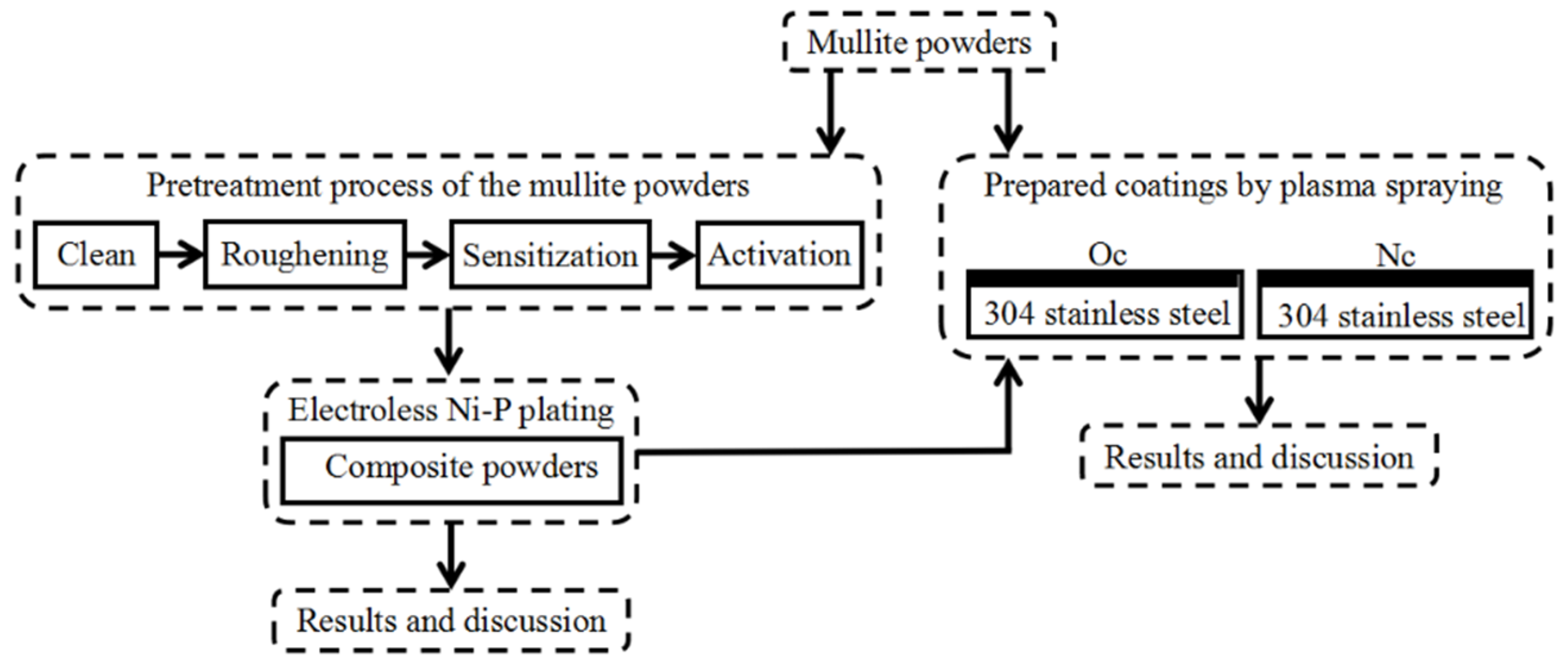
2.2. Preparation of the Ni–P-Coated Mullite Powders

2.2.1. Pretreatment of the Mullite Powders

The surface modification is illustrated in Figure 1. Mullite powders were pretreated before electroless plating. The steps included coarsening, sensitization, and activation. The mullite powders were dipped into a 25 wt.% HF solution for 10 min to obtain a coarse surface. The coarsened mullite powders were immersed into a solution of 16 g/L SnCl2 and 40 mL/L HCl at 40 °C for 20 min. Finally, the mullite powders were poured into an activator solution containing 0.3 g/L PdCl2 and 4 mL/L HCl at 40 °C for 40 min, which improved the subsequent interaction between the surface and electroless plating solution. After coarsening, the mullite powders were rinsed with a large volume of deionized water to neutralize the pH and dried after activation. During the activation process, Pd2+ ions were reduced to Pd atoms by Sn2+, which was ready for the next electroless Ni–P plating.

2.2.2. Orthogonal Experimental Design of Electroless Plating

The parameters of the plating solution were optimized by an orthogonal test. Four factors were considered in this experiment: [NiSO4·6H2O] (A), [NaH2PO2·H2O] (B), temperature (C), and pH (D). Through measuring the relative weight gain of 1g powders after electroless plating, the optimal process parameters of the Ni–P plating on the mullite powder surface were obtained: [NiSO4·6H2O] = 20 g/L, [NaH2PO2·H2O] = 30 g/L, temperature = 80 °C, and pH = 5.5. Table 2 shows the design factors along with their levels.

2.2.3. Electroless Plating with Ni–P

The electroless Ni–P plating was carried out on the pretreated mullite powders with the optimal bath parameters. The electroless plating was conducted at 80 °C for 1 h. The powders were suspended by magnetic stirrers during the reaction to achieve a good plating effect. After the reaction, the coated powders were separated from the solution by filtration and washed three times with deionized water. Finally, the Ni–P/mullite composite powders were obtained after drying at 100 °C for 3 h.
In the process of electroless Ni–P plating, the initiation of Ni–P deposition is controlled by an anodic process. The first step involves a non-Faradaic step, namely the adsorption of hypophosphite on the surface of the catalyst [22]. Then the homolytic breakdown of Ni–P bond occurs. The hydrogen in the reaction comes from the reducing agent sodium hypophosphite. The homolytic breakdown of Ni–P bond not only accelerates the deposition rate of the secondary phosphate ion dehydrogenation but also improves the activity of H2PO2 [19]. In the process of plating, the Ni–P layer is first deposited near the catalyst. The chemical reactions during electroless plating are depicted as follows:
H 2 PO 2 HPO 2 + H
HPO 2 + H 2 O H 2 PO 3 + H + + e
H + H H 2
2 H + + 2 e H 2
Ni 2 + + 2 e Ni
H 2 PO 2 + 2 H + + 2 e P + 2 H 2 O

2.3. Preparation of Coatings

Before the plasma spray deposition, the stainless-steel substrate was sand-blasted with 300 μm SiC particles and cleaned with an acetone solution in an ultrasonic bath for 15 min to roughen the surface and ensure good adhesion between the coating and substrate. A NiCrAlY bond coating (approximately 100 μm) was sprayed on the substrate before the preparation of the mullite coating to reduce the residual thermal stress between the substrate and coating. The coatings fabricated by original mullite powders and coated mullite powders are denoted as OC and NC, respectively. The APS parameters selected in this study are shown in Table 3.

2.4. Thermal Cycle Test of the Coatings

The thermal cycle tests were carried out in a muffle furnace (SX-G07123, Tianjin zhonghuan electric furnace Co., Ltd., Tianjin, China, 10 °C/min). After processing in a muffle furnace at 800 °C for 15 min, the sprayed samples were quickly removed from the furnace and cooled in water at 10 °C. When the samples were completely cooled, they were removed and dried with compressed air. At each interval of cooling, the furnace was maintained at 800 °C. The cooled samples were placed in the furnace again to conduct the second cycle of thermal tests. The process was repeated until an area equivalent to 5% of the coatings was debonded from the substrate. All the processes above were shown in Figure 2.

2.5. Characterization of the Coated Mullite Powders and As-Sprayed Coatings

Before the microscopic characterization, the coated powders were embedded in carbon powders, and then mechanically polished to obtain the cross section of the coated powders. The morphologies of the coated mullite powders and as-sprayed coatings were analyzed by scanning electron microscopy (SEM, JSM-6700F, JEOL, Tokyo, Japan) equipped with energy-dispersive spectrometry (EDS). X-ray photoelectron spectroscopy (XPS; PHI-5702, Al Kα radiation, Thermo Fisher Scientific, Massachusetts, America) was used to analyze the surface compositions and chemical states of the coated powders. To obtain the cross section morphologies of the coated powder and sprayed coating, the cross sections of the coated powder and coating were mechanically polished. The phase compositions of the coated mullite and the coatings were determined using X-ray diffraction (XRD; D8 ADVANCE, Cu-Kα radiation, Brukeroptics, Karlsruhe, Germany).
The microhardnesses of the polished surfaces of the as-prepared coatings were measured by an HDX-1000 digital hardness tester (Shangcai Testermachine Co., Ltd., shanghai, China) with a load of 200 g and dwell time of 10 s. The microhardnesses of the coatings were the average values of 15 indentation points. The porosities of the as-sprayed coatings were calculated by the software version Image J (National Institutes of Health, Bethesda, America). The densities(ρ) of the coatings were measured by water immersion. A DRE-III thermal conductivity instrument was used to determine the thermal diffusivity (α) and thermal conductivity (K) of the as-sprayed coating by the transient plane source (TPS) method. The specific heat capacity (Cp) of the coating was calculated as: K = αρCp.

3. Results and Discussion

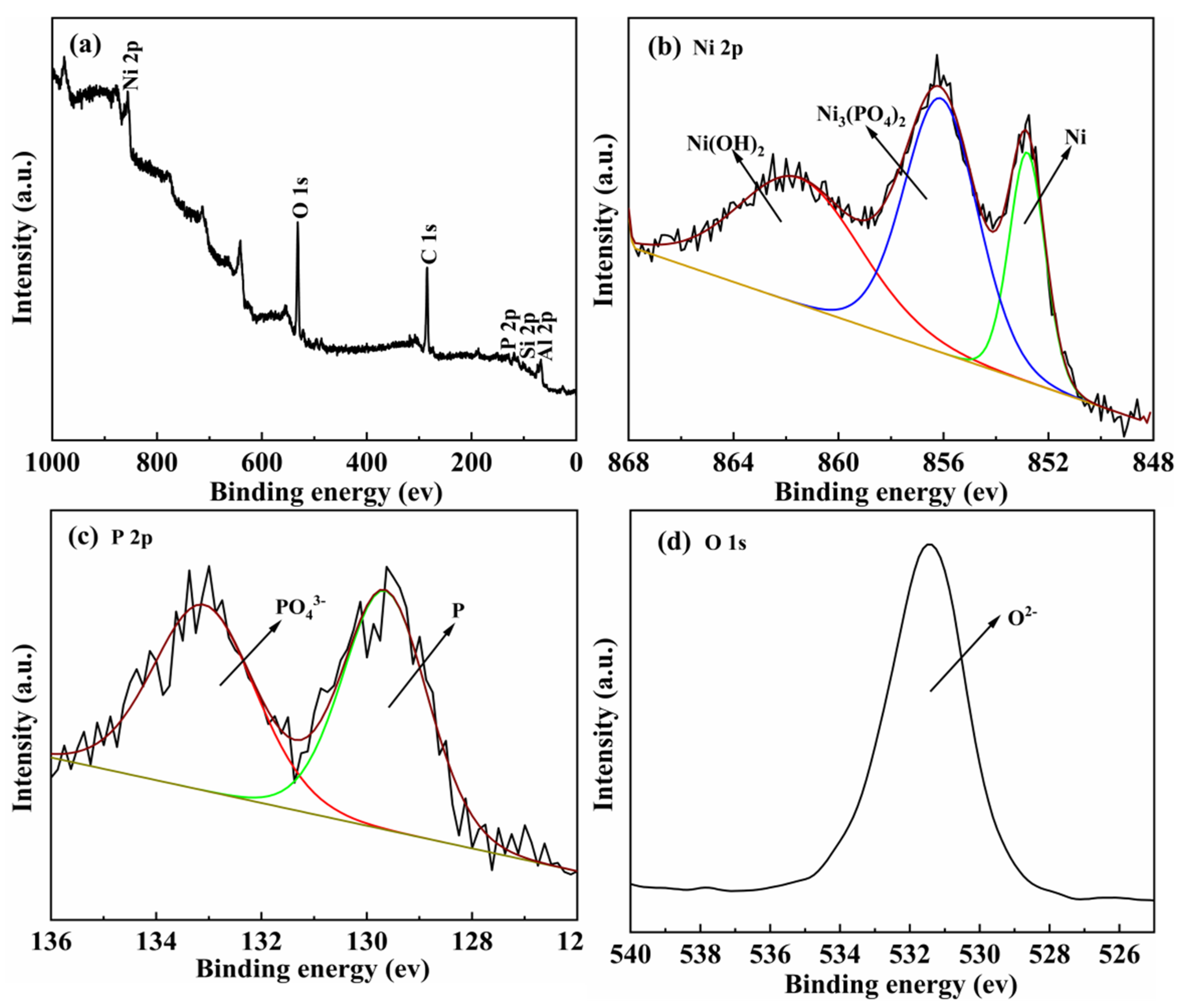
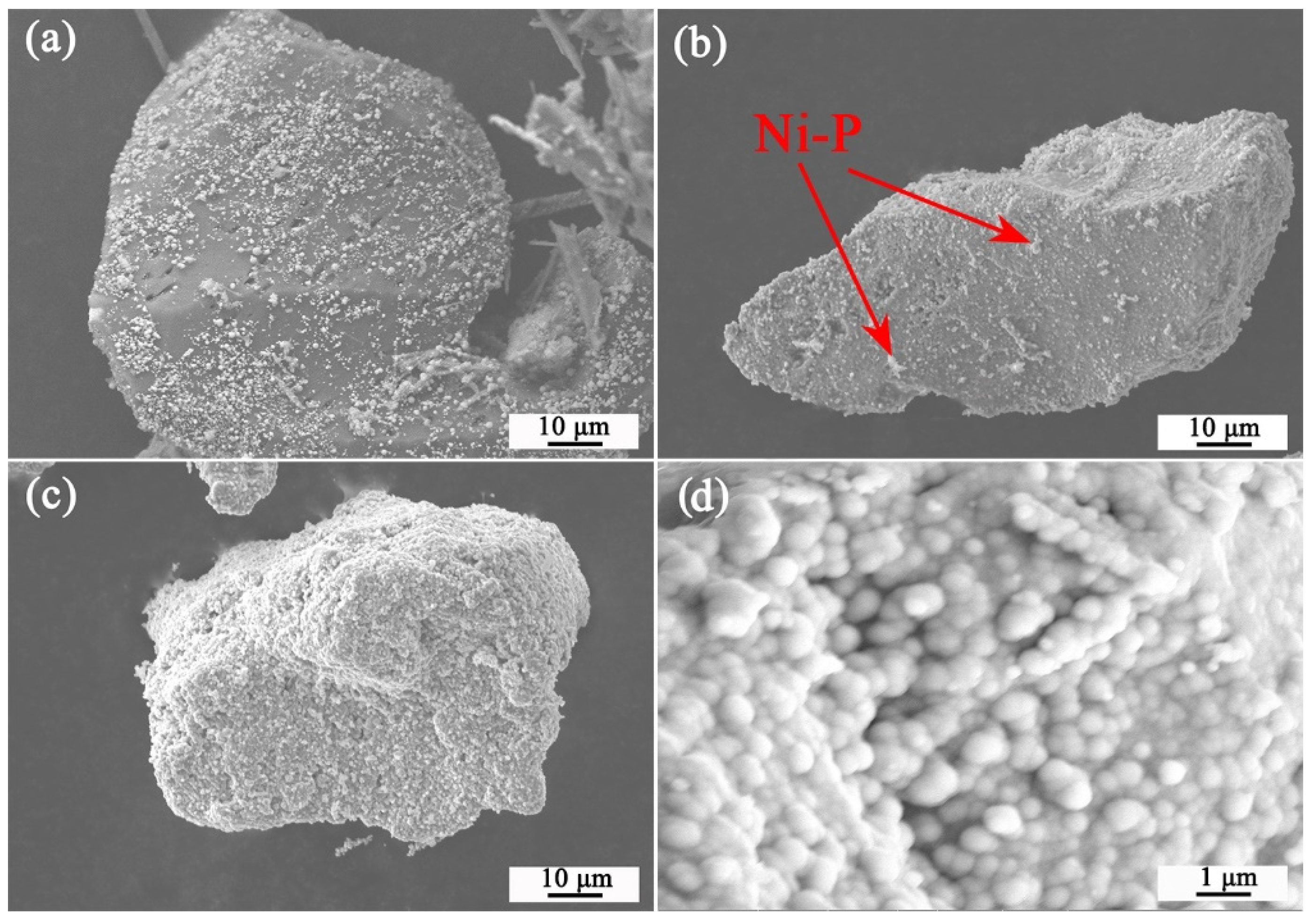
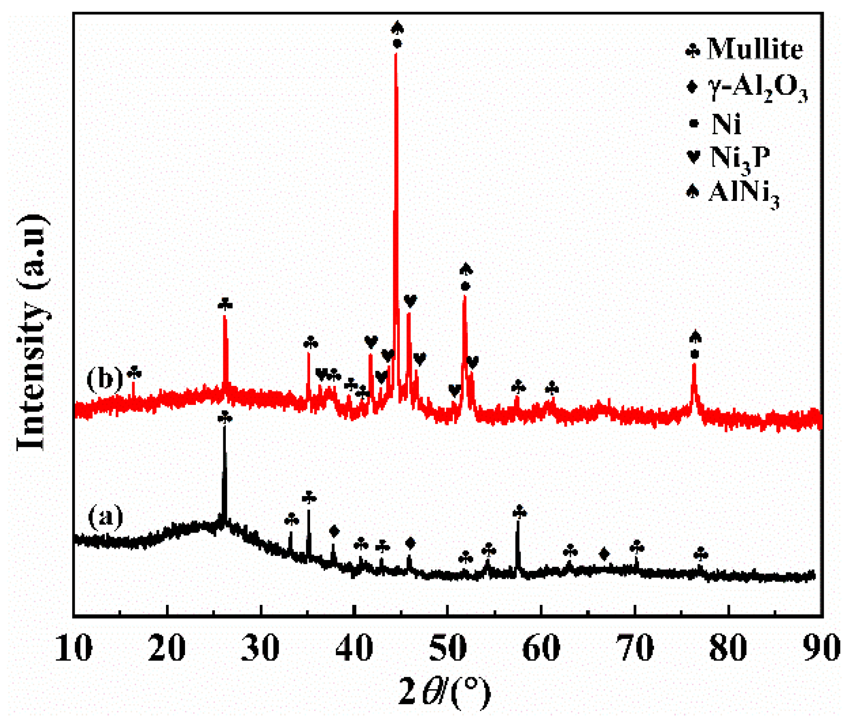
3.1. Microstructures and Phase Compositions of the Ni–P/Mullite Composite Powders

Figure 3 shows SEM images of the coated powders with different NaH2PO2·H2O concentrations when the others factors are constant. Figure 3d shows that the Ni–P layer is coated on the surface of the mullite powder. To better elucidate the nucleation and growth of the Ni–P layer in electroless plating, mullite powders were coated when the concentrations of NaH2PO2·H2O were 10, 20, and 30 g/L. Figure 3a shows that, under the catalysis of discontinuous Pd sites, Ni particles start to nucleate at the activation centers and grow in situ, which leads to an island-like structure and leakage plating phenomenon. Figure 3b illustrates that a uniform Ni–P layer was coated on the surface of mullite. Ni–P particles formed a secondary structure on the surface of mullite, because the deposited Ni–P film acted as an activation center, where a new island-shaped Ni nucleus was formed at the position of a Pd site. Notably, no obvious leakage of plating was observed. Figure 3c,d show that the Ni–P layer is uniformly distributed on the surface of the mullite powder without aggregation layer. A good Ni–P layer was formed on the surface of the mullite powder by orthogonal test.
Figure 4 shows the EDS analysis of the Ni–P/mullite composite powder under the optimized conditions. Figure 4c shows EDS results of area A in Figure 4a. It reveals that the Ni and P contents in the deposits are 83.22 and 5.82 wt.%, respectively. Figure 4d shows scanning results along line B in Figure 4b. Ni and P are distributed mainly on the surface of the composite powder, while Al, Si, and O are distributed in the core part of the composite powder. The average thickness of the Ni–P layer is approximately 2 μm when the plating is completed. These results combined with the SEM images show that a Ni–P layer is well formed on the surface of the mullite powder, which is conducive to bonding with the substrate.
The XRD patterns of the mullite powders, Ni–P/mullite coated powders, and coated powders after the heat treatment (850 °C for 60 min) are shown in Figure 5. As shown in Figure 5b, the coated powders exhibited a broad band at 2θ = 45°, which is a typical feature of the amorphous structure. During the plating process, the metalloid P was reduced into the Ni–P layer with Ni, which hindered the arrangement of Ni atoms into the face-centered cubic structure. Therefore, the layer microstructure gradually changed from microcrystalline to amorphous with a disordered arrangement [23]. Under the protection of argon, the coated powders were heat-treated at 850 °C for 60 min. As shown in Figure 5c, after the heat treatment, the broad band of the coated powders at 2θ = 45° disappeared; sharp crystal peaks of the equilibrium phases of Ni and Ni3P were formed. The layer changed from amorphous to crystalline. During the heat treatment, the Ni–P layer initially exhibited structural relaxation with the increase in temperature, and then diffusion migration of P occurred, which yielded the formation of Ni crystals and metastable intermediate phases, such as Ni8P3 and Ni12P5 [18,24]. As the temperature further increased, the metastable intermediate phases decomposed to Ni3P and, finally, the alloy transformed from amorphous to crystalline. During the heat treatment, the dispersed distribution of Ni3P precipitated by the recrystallization changed the arrangement of Ni and P atoms, which effectively prevented the movement of grain boundaries and dislocations [25].
The surface analysis of the Ni–P/mullite composite powder was carried out using XPS (Figure 6). Figure 6a shows C, O, Al, Si, Ni, and P elements on the surface of the mullite powder. C in the spectrum originated mainly from surface contamination [26]. Ni is one of the elements with the highest contents, while the content of P is relatively low. This indicates that the Ni–P layer was coated on the surface of the mullite powders during the electroless plating. To characterize the surface chemical state of the coated powder, high-resolution XPS spectra of Ni 2p, P 2p, and O 1s were acquired. The spectrum of Ni 2p3/2 (Figure 6b) is decomposed into three peaks. According to the reference [24], the peak at 856.1 ± 0.1 eV is attributed to Ni2+ in Ni3(PO4)2. The peaks at 861.5 ± 0.1 and 852.8 ± 0.1 eV are attributed to Ni2+ in Ni(OH)2 and Ni in the layer, respectively. In Figure 6c, the high-resolution curves of P 2p3/2 are composed mainly of two peaks at 129.6 ± 0.1 and 133.0 ± 0.1 eV. The peak at 129.6 ± 0.1 eV originates from P in the layer, while the peak at 133.0 ± 0.1 eV is attributed to P5+ in Ni3(PO4)2. Figure 6d shows the high-resolution spectrum of O 1s, which corresponds to mainly O2− in a series of oxygen-containing compounds. The XPS spectrum shows that the surface of the coated powder layer is composed mainly of Ni3(PO4)2, Ni(OH)2, Ni, and P.

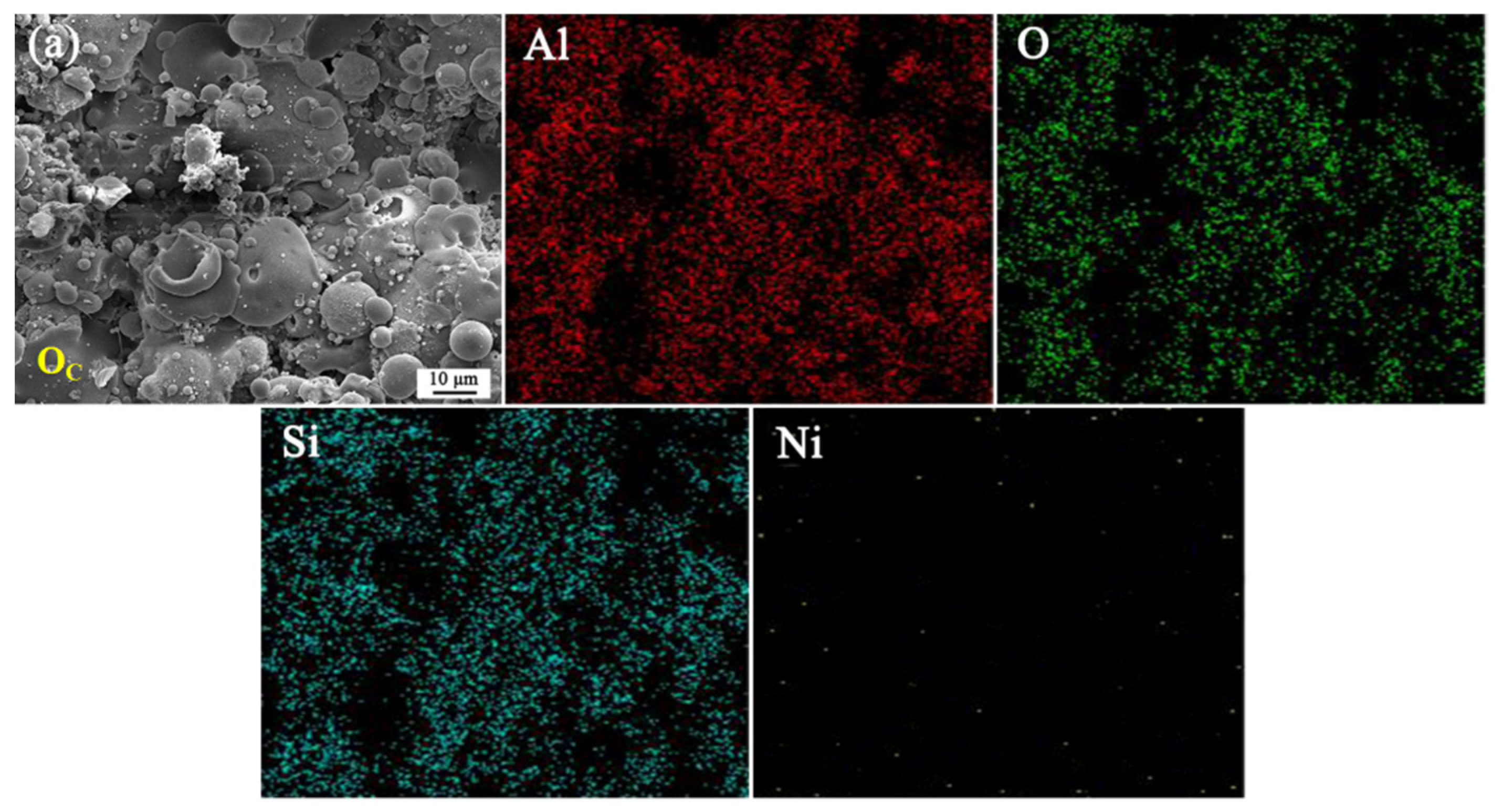
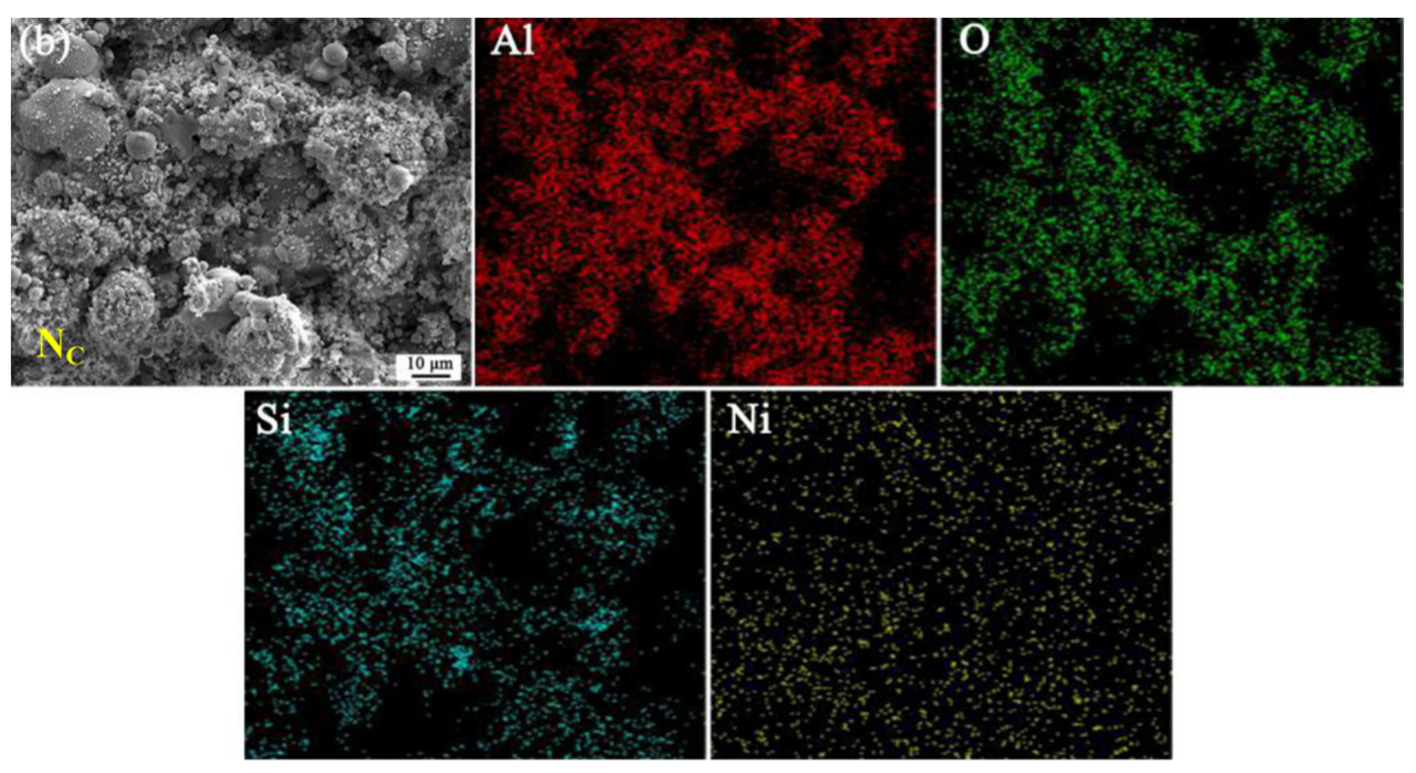
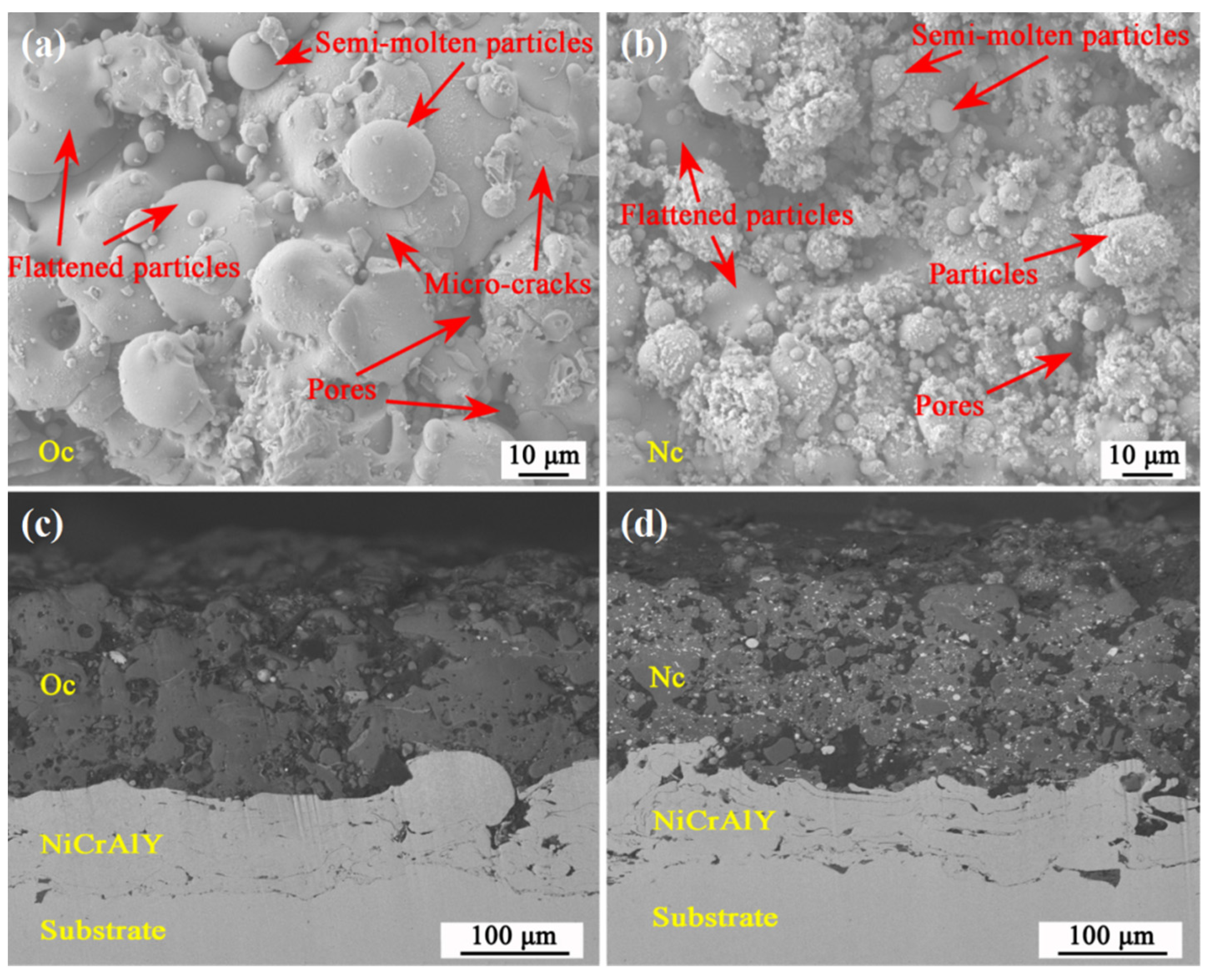
3.2. Microstructure and Phase Compositions of the Coatings

Figure 7 shows top views of the as-sprayed coatings and their polished cross sections. As shown in Figure 7a,b, the as-sprayed coatings are relatively rough and contain numerous flattened particles, some semimolten particles, and few pores. Compared to OC (Figure 7a), the coated mullite powders in NC (Figure 7b) were partially melted, while some mullite powders were uniformly embedded in the area of the flattened zone and semimolten powders. This may be attributed to the presence of the Ni–P layer on the surface of the coated powders. At the same power, the particles injected in the center of the plasma jet can be completely melted and can form molten droplets that are accelerated to hit the substrate with a high kinetic energy. While the particles were injected at the periphery of the plasma jet, a part of the spraying heat was absorbed by the Ni–P layer. As a result, a part of the coated mullite powder was directly embedded on the surface of the substrate without melting [27]. There were no obvious cracks between the mullite coating and metallic layer. Figure 7c,d shows back-scattered electron (BSE) images of Oc and Nc, respectively. Compared to OC, there are numerous white spots of the Ni–P layer uniformly distributed in the cross section of NC. There are also a few pores in the coating, which mainly originate from the escape of gas inside the coating and boundary closure of the melting zone.
The properties of composites depend largely on the homogeneity of the mixed phases. Figure 8 shows the surfaces of the as-sprayed mullite coatings and corresponding energy spectrum analysis. Al, O, and Si are uniformly distributed on the surfaces of the mullite coatings; there is no concentration of elements on the surface. Compared to OC (Figure 8a), the energy spectrum analysis of NC (Figure 8b) shows that Ni elements are uniformly distributed in the top coating.
Figure 9 shows the XRD patterns of the as-sprayed mullite coatings. OC is mainly composed of mullite, whereas γ-Al2O3 is present as a minor phase. In addition, there is a broad band of an amorphous phase at 2θ between 20° and 40°. The existence of the amorphous phase is attributed to the large temperature gradient between the molten particles and substrate. The molten particles quickly hit the substrate and rapidly cool to form the amorphous phase. In addition, the metastable γ-Al2O3 phase in OC does not change to the stable α-Al2O3 owing to the high cooling rate [28]. The XRD pattern shows that NC (Figure 9b) is mainly composed of mullite, Ni, Ni3P, and AlNi3 phases. The crystal peak of mullite is attributed to the molten particles but also originates from the unfused mullite particles embedded on the substrate. The high-speed plasma flame melts the Ni–P layer on the surface of the coated mullite powders and some coated mullite powders, forming hard phases such as Ni3P and AlNi3, which is beneficial to the improvement in hardness.

3.3. Hardness and Thermal Conductivity of the Coatings

Hardness is one of the main indices of wear resistance of the coating. Because of some inherent defects of plasma spraying, the hardness and porosity of the spraying coating are different from those of their corresponding bulk materials. Figure 10 shows the hardnesses and porosities of the substrate, bonding coating, and coatings. The hardness gradually increases from the substrate to NC. The porosities (measured by version Image J) of Oc and Nc are 11.15% ± 0.32% and 7.40% ± 0.51%, respectively, which implies that the introduction of the Ni–P layer leads to a minor reduction in porosity of the mullite coating. The bonding coating also has a small amount of pores; the substrate is a bulk material without pores. The hardness of the coating is related to the number of lipostomous in the coating. Compared to the Vickers hardness of OC (417.5 ± 46.1 HV), the hardness of NC (500.1 ± 33.6 HV) is significantly increased. This can be explained as the introduction of the Ni–P layer not only reduces the internal pores of NC and improves the compactness, but also leads to the formation of hard phases such as Ni3P and AlNi3 in NC. The unmelted mullite powders in NC also increase the hardness of the coating. A proper coating porosity is helpful to enhance the thermal insulation properties in high-temperature applications. However, a high porosity is harmful to the protection of the metallic substrate and service life of the coating at a high temperature. The pores are similar to channels; oxygen permeates through the open pores and reacts with the bonding layer to form oxides, which reduces the service life of the coating [29,30].
Thermal insulation is crucial for the TBC. A functional TBC can effectively hinder the heat transfer between the environment and substrate. Table 4 shows the densities, specific heat capacities, thermal diffusivities, and thermal conductivities of the as-sprayed coatings at 25 °C. The density of NC is slightly larger than that of OC, owing to the Ni–P layer and to the fewer pores in NC. According to the TPS measurement, the thermal conductivities of Oc and Nc are 3.356 and 3.540 (W/m·K), respectively. The measured thermal conductivities are different from the reported values of 1 to 2.8 (W/m·K) [11,30], which may be related to the measurement method and coating thickness [31]. The thermal insulation performance of the coating prepared by APS is directly proportional to the coating thickness. In other studies, the thicknesses of TBCs were 500 to 1000 μm, while that in this study is approximately 200 μm, so that the thermal conductivity is increased. When heat is transferred in the coating, the pores of the coating can cause turbulence to the propagation path of the phonons in the heat transfer medium [32]. In the plasma sprayed coatings, the pores are basically flat and parallel to the substrate, which increases the resistance against the heat flow in the vertical direction across the whole coating. Thus, a proper porosity is helpful to the thermal insulation of the coating. Although the low porosity of NC is harmful to the thermal barrier properties of the coating, the crystal structure of NC is complex with numerous heterogeneous phases, which enhance the scattering of electrons and phonons in the heat transfer medium and largely affect the heat transfer ability of the coating. Therefore, compared to OC, the introduction of the Ni–P layer in NC does not significantly increase its thermal conductivity.

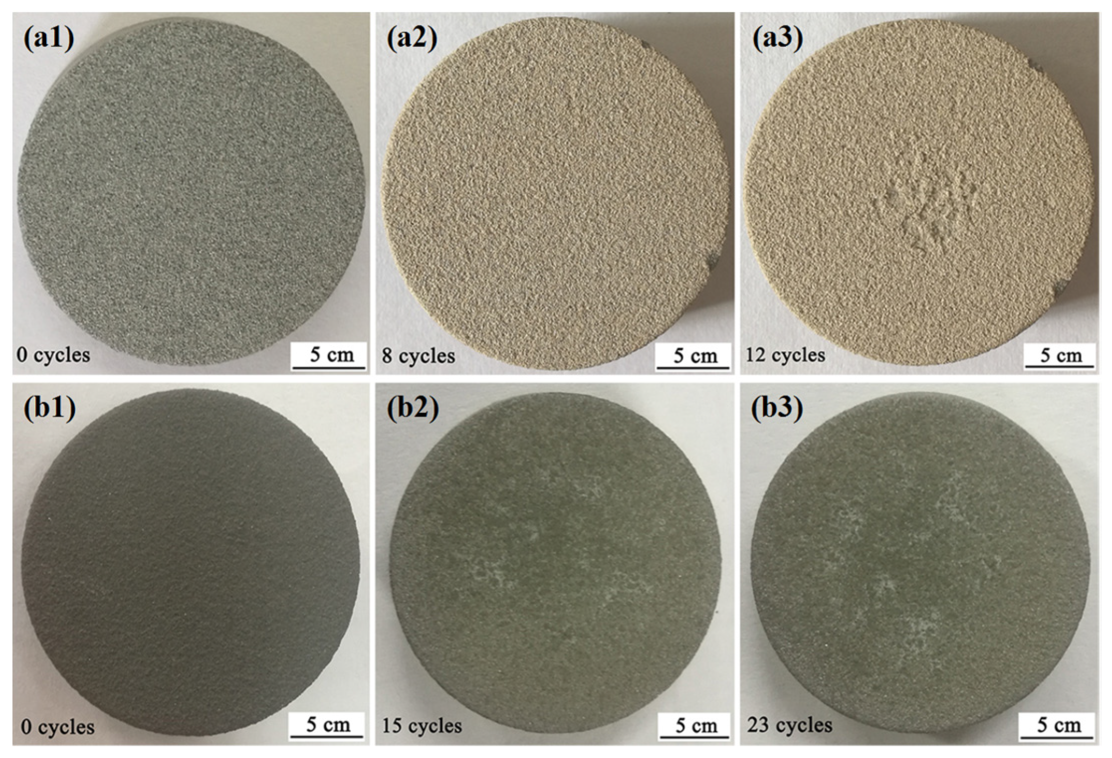
3.4. Thermal Cycling Resistances of the Coatings

Figure 11 shows digital photographs of the thermal shock cycling of the coatings. Before the cycles of thermal shock, NC (Figure 11b1–b3) is grayish black, owing to the coated mullite powders. After 8 cycles of thermal shock, the color of OC (Figure 11a1–a3) changes to yellowish brown and the edge of the coating is slightly detached from the substrate. After 12 cycles of thermal shock, the spalling area at the edge of OC expands slightly and a considerable spalling occurs at the center of the coating. At this time, the OC is considered to fail. After 15 thermal shocks, NC becomes gray and slightly peels off locally. When NC is subjected to 23 cycles of thermal shock, the spalling area of the coating is considerably increased, but no spalling occurs at the edge of NC. At this time, NC fails. During the thermal shock, the main reasons for coating failure are the mismatch in CTE and formation of thermally grown oxide (TGO) [33,34]. When OC is subjected to thermal shock, the CTEs of OC and bonding layer are not matched (mullite, 5.3 × 10⁻⁶/K; NiCrAlY, 15.4 × 10⁻⁶/K), which accumulates residual stress at the interface between the coating and bonding layer. With the increase in the number of thermal shocks, the residual stress increases gradually and ultimately leads to the failure of the coating [35]. In NC, the introduction of the Ni–P layer can effectively improve the CTE of the coating and increase the wettability and adhesion between the coating and the bond layer, which can effectively reduce the spalling of the coating. Moreover, the pores are important channels for the generation of TGO. A proper thickness of TGO is useful to prevent further oxidation of the coating and improve the system durability. However, a large residual stress is formed when the thickness of TGO is too large, which eventually leads to the failure of the coating [36]. Compared to OC, the reduction of pores in NC effectively prevents the formation of TGO and improves the service life of the coating at high temperatures.

4. Conclusions

The mullite powders were coated with the Ni–P layer by electroless plating. The coated mullite powders and original mullite powders were then plasma-sprayed onto 304 stainless-steel substrates to form mullite coatings. The growth mechanism of the Ni–P layer, microstructures and phase compositions of the coated powders, and properties of the as-sprayed coatings were investigated. The conclusions of this study can be summarized as follows:
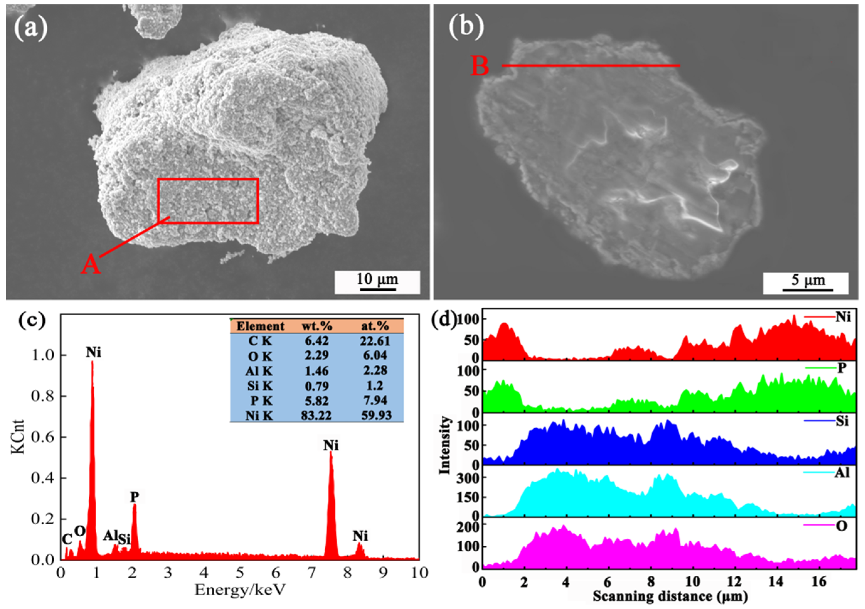
  • The Ni–P layer could be coated on the surface of mullite powders by electroless plating. The layer of coated powder was uniform and dense, without leakage or aggregation.
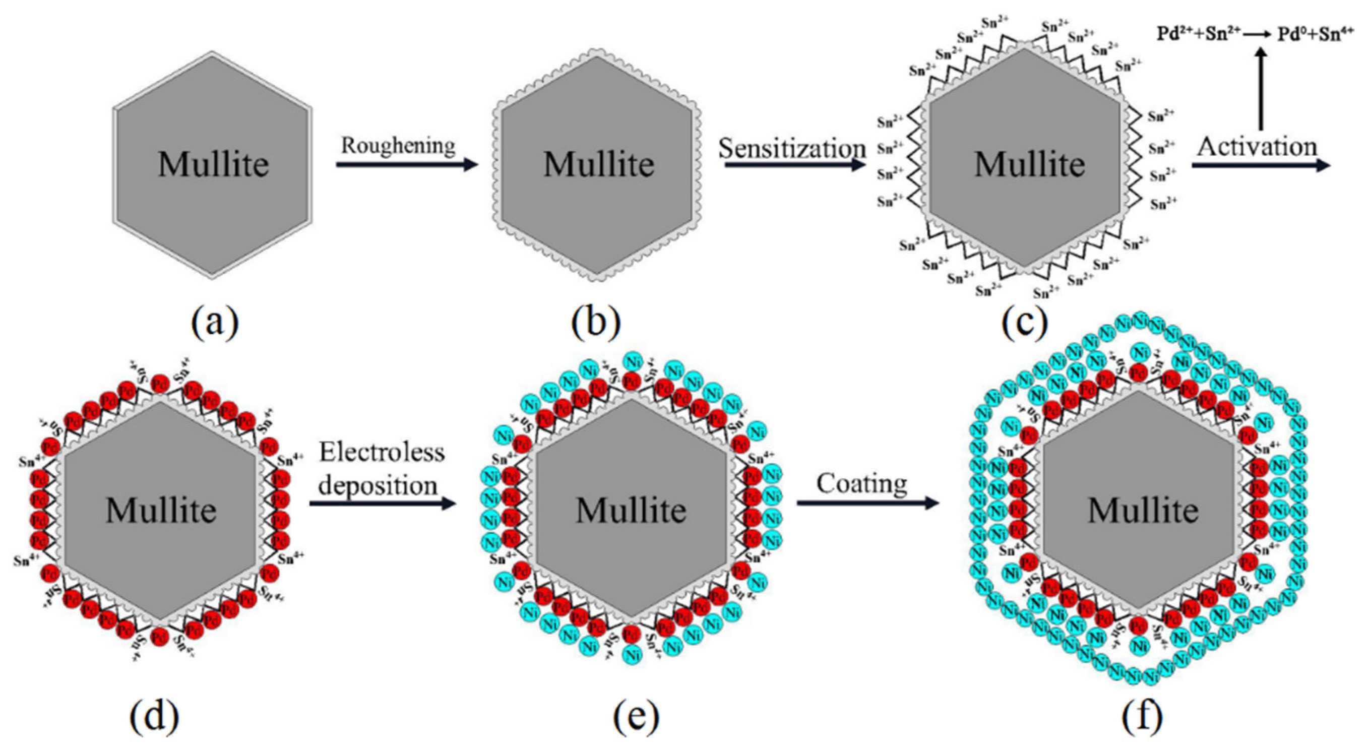
  • In the electroless plating, Ni2+ was absorbed on the surface of the pretreated mullite and reduced to nucleate growth near the Pd atom, forming an island-like structure. With the reaction, Ni particles grew and aggregated in three dimensions, forming a Ni–P layer film on the surface of the mullite. The Ni particles formed on the surface of the film served as activation centers for reaction continuation.
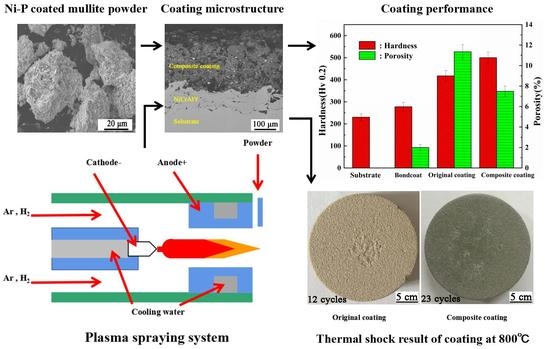
  • Compared to the original mullite coating, the composite coating with the Ni–P layer exhibited a better wettability, lower porosity, higher hardness, and larger binding force under the condition that the thermal conductivity is not significantly different from that of the original mullite coating. This study provides a feasible approach for the applications of mullite as a wear-resistance material of harsh environments, environmental barrier coatings (EBCs) of the ceramic matrix composite material and TBCs of lower-temperature environments.

Author Contributions

Conceptualization, K.C.; Formal analysis, K.C.; Investigation, P.Z. and X.N.; Project administration, P.Z.; Writing—original draft, K.C.; Writing—review and editing, P.S., X.N. and C.H. All authors have read and agreed to the published version of the manuscript.

Funding

This study was supported by Research Projects of Higher-Education Institutions in Gansu Province (2017D-02).

Institutional Review Board Statement

Not applicable.

Informed Consent Statement

Not applicable.

Data Availability Statement

Data is contained within the article.

Conflicts of Interest

There are no conflict of interest to declare.

References

  1. Padture, N.P.; Gell, M.; Jordan, E.H. Thermal barrier coatings for gas-turbine engine applications. Science 2002, 296, 280–284. [Google Scholar] [CrossRef]
  2. Cao, X.Q.; Vassen, R.; Stoever, D. Ceramic materials for thermal barrier coatings. J. Eur. Ceram. Soc. 2004, 24, 1–10. [Google Scholar] [CrossRef]
  3. Vaßen, R.; Jarligo, M.O.; Steinke, T.; Mack, D.E.; Stöver, D. Overview on advanced thermal barrier coatings. Surf. Coat. Technol. 2010, 205, 938–942. [Google Scholar] [CrossRef]
  4. Vaßen, R.; Kagawa, Y.; Subramanian, R.; Zombo, P.; Zhu, D. Testing and evaluation of thermal-barrier coatings. MRS Bull. 2012, 37, 911–916. [Google Scholar] [CrossRef]
  5. Ghasemi, R.; Shoja-Razavi, R.; Mozafarinia, R.; Jamali, H. The influence of laser treatment on thermal shock resistance of plasma-sprayed nanostructured yttria stabilized zirconia thermal barrier coatings. Ceram. Int. 2014, 40, 347–355. [Google Scholar] [CrossRef]
  6. Narimani, N.; Saremi, M. A study on the oxidation resistance of electrodeposited and nanostructured YSZ thermal barrier ceramic coatings. Ceram. Int. 2015, 41, 13810–13816. [Google Scholar] [CrossRef]
  7. Jam, A.; Derakhshandeh, S.M.R.; Rajaei, H.; Pakseresht, A.H. Evaluation of microstructure and electrochemical behavior of dual-layer NiCrAlY/mullite plasma sprayed coating on high silicon cast iron alloy. Ceram. Int. 2017, 43, 14146–14155. [Google Scholar] [CrossRef]
  8. Hu, X.X.; Xu, F.F.; Li, K.W.; Jin, G.; Xu, Y.; Zhao, X.Q. Water vapor corrosion behavior and failure mechanism of plasma sprayed mullite/Lu2Si2O7-Lu2SiO5 coatings. Ceram. Int. 2018, 44, 14177–14185. [Google Scholar] [CrossRef]
  9. Saravanan, S.; Kumar, C.R.; Pugazhendhi, A.; Brindhadevic, K. Role of thermal barrier coating and porous medium combustor for a diesel engine: An experimental study. Fuel 2020, 280, 118597. [Google Scholar] [CrossRef]
  10. di Girolamo, G.; Blasi, C.; Pilloni, L.; Schioppa, M. Microstructural and thermal properties of plasma sprayed mullite coatings. Ceram. Int. 2010, 36, 1389–1395. [Google Scholar] [CrossRef]
  11. Li, S.J.; Zhao, X.Q.; Hou, G.L.; Deng, W.; An, Y.L.; Zhou, H.D.; Chen, J.M. Thermomechanical properties and thermal cycle resistance of plasma-sprayed mullite coating and mullite/zirconia composite coatings. Ceram. Int. 2016, 42, 17447–17455. [Google Scholar] [CrossRef]
  12. Rangaraj, S.; Kokini, K. Interface thermal fracture in functionally graded zirconia–mullite–bond coat alloy thermal barrier coatings. Acta Mater. 2003, 51, 251–267. [Google Scholar] [CrossRef]
  13. Bolelli, G.; Cannillo, V.; Lugli, C.; Lusvarghi, L.; Manfredini, T. Plasma-sprayed graded ceramic coatings on refractory materials for improved chemical resistance. J. Eur. Ceram. Soc. 2006, 26, 2561–2579. [Google Scholar] [CrossRef]
  14. Naebe, M.; Shirvanimoghaddam, K. Functionally graded materials: A review of fabrication and properties. Appl. Mater. Today 2016, 5, 223–245. [Google Scholar] [CrossRef]
  15. Wang, C.; Cui, X.F.; Jin, G.; Gao, Z.H.; Jin, J.N.; Cai, Z.B.; Fang, Y.C. Ceramic Fibers Reinforced Functionally Graded Thermal Barrier Coatings. Adv. Eng. Mater. 2017, 19, 1700149. [Google Scholar] [CrossRef]
  16. Zhang, X.F.; Song, J.B.; Deng, Z.Q.; Wang, C.; Niu, S.P.; Liu, G.; Deng, C.M.; Deng, C.G.; Liu, M.; Zhou, K.S.; et al. Interface evolution of Si/Mullite/Yb2SiO5 PS-PVD environmental barrier coatings under high temperature. J. Eur. Ceram. Soc. 2020, 40, 1478–1487. [Google Scholar] [CrossRef]
  17. Vakilifard, H.; Ghasemi, R.; Rahimipour, M. Hot corrosion behaviour of plasma-sprayed functionally graded thermal barrier coatings in the presence of Na2SO4 + V2O5 molten salt. Surf. Coat. Technol. 2017, 326, 238–246. [Google Scholar] [CrossRef]
  18. Luo, H.; Leitch, M.; Zeng, H.B.; Luo, J.L. Characterization of microstructure and properties of electroless duplex Ni-W-P/Ni-P nano-ZrO2 composite coating. Mater. Today. Phys. 2018, 4, 36–42. [Google Scholar] [CrossRef]
  19. Fan, L.; Wang, Q.; Yang, P.; Chen, H.H.; Hong, H.P.; Zhang, W.T.; Ren, J. Preparation of nickel coating on ZTA particles by electroless plating. Ceram. Int. 2018, 44, 11013–11021. [Google Scholar] [CrossRef]
  20. Liu, W.N.; Qiao, X.J.; Liu, S.; Shi, S.M.; Liang, K.; Tang, L. A new process for pre-treatment of electroless copper plating on the surface of mica powders with ultrasonic and nano-nickel. J. Alloy. Compd. 2019, 791, 613–620. [Google Scholar] [CrossRef]
  21. Kong, D.H.; Zuo, X.Q.; Wang, Y.W.; Zhou, Y. Microstructure and thermal decomposition property of Ni-P/Cr2N composite powder by electroless plating. Adv. Powder Technol. 2018, 29, 1433–1438. [Google Scholar] [CrossRef]
  22. Dai, H.; Li, H.; Wang, F. Electroless Ni–P coating preparation of conductive mica powder by a modified activation process. Appl. Surf. Sci. 2006, 253, 2474–2480. [Google Scholar] [CrossRef]
  23. Yuan, X.T.; Sun, D.B.; Yu, H.Y.; Meng, H.M.; Fan, Z.S.; Wang, X.D. Preparation of amorphous-nanocrystalline composite structured Ni–P electrodeposits. Surf. Coat. Technol. 2007, 202, 294–300. [Google Scholar] [CrossRef]
  24. Chen, J.; Zhao, G.L.; Matsuda, K.; Zou, Y. Microstructure evolution and corrosion resistance of Ni–Cu–P amorphous coating during crystallization process. Appl. Surf. Sci. 2019, 484, 835–844. [Google Scholar] [CrossRef]
  25. Ghavidel, N.; Allahkaram, S.R.; Naderi, R.; Barzegar, M.; Bakhshandeh, H. Corrosion and wear behavior of an electroless Ni-P/nano-SiC coating on AZ31 Mg alloy obtained through environmentally-friendly conversion coating. Surf. Coat. Technol. 2020, 382, 125156. [Google Scholar] [CrossRef]
  26. van den Brand, J.; Sloof, W.G.; Terryn, H.; de Wit, J.H.W. Correlation between hydroxyl fraction and O/Al atomic ratio as determined from XPS spectra of aluminium oxide layers. Surf. Interface. Anal. 2004, 36, 81–88. [Google Scholar] [CrossRef]
  27. An, Y.L.; Chen, J.M.; Zhou, H.D.; Liu, G. Microstructure and thermal cycle resistance of plasma sprayed mullite coatings made from secondary mullitized natural andalusite powder. Surf. Coat. Technol. 2010, 205, 1897–1903. [Google Scholar] [CrossRef]
  28. Li, S.J.; Xi, X.; Hou, G.L.; An, Y.L.; Zhao, X.Q.; Zhou, H.D.; Chen, J.M. Preparation of plasma sprayed mullite coating on stainless steel substrate and investigation of its environmental dependence of friction and wear behavior. Tribol. Int. 2015, 91, 32–39. [Google Scholar] [CrossRef]
  29. Rad, M.R.; Farrahi, G.H.; Azadi, M.; Ghodrati, M. Stress analysis of thermal barrier coating system subjected to out-of-phase thermo-mechanical loadings considering roughness and porosity effect. Surf. Coat. Technol. 2015, 262, 77–86. [Google Scholar]
  30. See, A.; Hassan, J.; Hashim, M.; Wahab, Z.A. Thermal diffusivity of kaolinite–mullite ceramic matrix composite with silicon nitride nanoparticle filler. Thermochim. Acta. 2014, 593, 76–81. [Google Scholar] [CrossRef]
  31. Izadinia, M.; Soltani, R.; Sohi, M.H. Effect of segmented cracks on TGO growth and life of thick thermal barrier coating under isothermal oxidation conditions. Ceram. Int. 2020, 46, 7475–7481. [Google Scholar] [CrossRef]
  32. Foroushani, M.H.; Shamanian, M.; Salehi, M.; Davar, F. Porosity analysis and oxidation behavior of plasma sprayed YSZ and YSZ/LaPO4 abradable thermal barrier coatings. Ceram. Int. 2016, 42, 15868–15875. [Google Scholar] [CrossRef]
  33. Liu, P.F.; Jiang, P.; Sun, Y.L.; Xu, R.; Wang, T.J.; Zhang, W.X. Numerical Analysis of stress evolution in thermal barrier coating system during two-stage growth of heterogeneous oxide. Ceram. Int. 2021, 47, 14311–14319. [Google Scholar] [CrossRef]
  34. Shen, Z.Y.; Liu, G.X.; Mu, R.D.; He, L.M.; Xu, Z.H.; Dai, J.W. Effects of Er stabilization on thermal property and failure behavior of Gd2Zr2O7 thermal barrier coatings. Corros. Sci. 2021, 185, 109418. [Google Scholar] [CrossRef]
  35. Hussain, N.; Qayyum, F.; Pasha, R.A.; Shah, M. Development of multi-physics numerical simulation model to investigate thermo-mechanical fatigue crack propagation in an autofrettaged gun barrel. Def. Technol. 2021, 17, 1579–1591. [Google Scholar] [CrossRef]
  36. Mukhtar, F.; Qayyum, F.; Elahi, H.; Shah, M. Studying the effect of thermal fatigue on multiple cracks propagating in an SS316L thin flange on a shaft specimen using a multi-physics numerical simulation model. J. Mech. Eng. 2019, 65, 565–573. [Google Scholar] [CrossRef]
Figure 1. Electroless Ni–P plating.
Coatings 12 00018 g001
Figure 2. The flow chart of the experimental process.
Coatings 12 00018 g002
Figure 3. SEM images of the Ni–P layers with NaH2PO2·H2O concentrations of (a) 10, (b) 20, and (c) 30 g/L. (d) Magnified image of (c).
Coatings 12 00018 g003
Figure 4. EDS analysis of the Ni–P/mullite composite powder: (a) surface, (b) cross section, (c) EDS of area A, and (d) scans along line B.
Coatings 12 00018 g004
Figure 5. XRD patterns of the powders before and after the electroless plating: (a) raw mullite powders, (b) Ni–P/mullite composite powders, and (c) heat treatment at 850 °C for 60 min.
Coatings 12 00018 g005
Figure 6. XPS spectra of Ni–P/mullite coated powder: (a) full spectra, (b) Ni 2p narrow spectra, (c) P 2p narrow spectra and (d) O 1s narrow spectra.
Coatings 12 00018 g006
Figure 7. SEM images of the top surfaces of the as-sprayed coatings: (a) OC, (b) NC, and (c,d) their polished cross sections (mode: BSE), respectively.
Coatings 12 00018 g007
Figure 8. SEM images of the surfaces of the mullite coatings and corresponding energy. Spectrum analysis: (a) OC, (b) NC.
Coatings 12 00018 g008aCoatings 12 00018 g008b
Figure 9. XRD patterns of the as-sprayed coatings: (a) OC, (b) NC.
Coatings 12 00018 g009
Figure 10. Hardnesses and porosities of the substrate, bonding coating and as-sprayed coatings.
Coatings 12 00018 g010
Figure 11. Digital photographs during the thermal shock cycling of the as-sprayed coatings: (a1) OC 0 cycles, (a2) OC 8 cycles, (a3) OC 12 cycles, (b1) NC 0 cycles, (b2) NC 15 cycles, (b3) NC 23 cycles.
Coatings 12 00018 g011
Table 1. Chemical composition of the 304 stainless steel.
ElementCSiMnPSNiCrNFe
wt.%0.070.371.270.030.018.0217.20.06Balance
Table 2. Design factors and their levels.
LevelFactor
Nickel Sulfate
Hexahydrate (A)/(g/L)
Sodium Hypophosphite (B)/(g/L)Temperature (C)/℃pH (D)
11510404.5
22020605
32530805.5
The optimal factor2030805.5
Table 3. APS parameters.
ParametersNiCrAlY CoatingMullite Coating
Arc current (A)600500
Voltage (V)6070
Argon gas flow rate (L/min)4045
Hydrogen gas flow rate (L/min)1515
Powder gas flow rate (L/min)58
Spray distance (mm)9090
Spray angle (°)9090
Gun speed (m/s)0.30.2
Table 4. Densities, specific heat capacities, thermal diffusivities, and thermal conductivities of the as-sprayed coatings.
SampleDensity (g/cm3)Specific Heat
Capacity (kJ/kg·K)
Thermal Diffusivity (mm2/S)Thermal Conductivity (W/m·K)
OC2.7441.3530.9043.356
NC3.0150.9761.2033.540
Oc/Nc (%)91.01138.6375.1594.80
Publisher’s Note: MDPI stays neutral with regard to jurisdictional claims in published maps and institutional affiliations.

