
Structural Evaluation of Coal-Tar-Pitch-Based Carbon Materials and Their Na+ Storage Properties

 ,
, 
Abstract
:1. Introduction
2. Materials and Methods
2.1. Characteristics
2.2. Preparations of Coal-Tar-Pitch-Based Carbon Materials
2.3. Preparation of S-Modified Coal-Tar-Pitches
2.4. Preparations of S-Modified Coal-Tar-Pitch-Based Carbon Materials
2.5. Electrochemical Measurements
3. Results
4. Conclusions
Supplementary Materials
Author Contributions
Funding
Institutional Review Board Statement
Informed Consent Statement
Data Availability Statement
Acknowledgments
Conflicts of Interest
References
- Min, X.; Xiao, J.; Fang, M.H.; Wang, W.; Zhao, Y.J.; Liu, Y.A.; Abdelkader, A.M.; Xi, K.; Kumar, R.V.; Huang, Z.H. Potassium-ion batteries: Outlook on present and future technologies. Energy Environ. Sci. 2021, 14, 2186–2243. [Google Scholar] [CrossRef]
- Lu, S.Y.; Zhu, T.X.; Wu, H.; Wang, Y.K.; Li, J.; Abdelkader, A.; Xi, K.; Wang, W.; Li, Y.G.; Ding, S.J.; et al. Construction of ultrafine ZnSe nanoparticles on/in amorphous carbon hollow nanospheres with high-power-density sodium storage. Nano Energy 2019, 59, 762–772. [Google Scholar] [CrossRef] [Green Version]
- Lu, S.Y.; Wu, H.; Hou, J.W.; Liu, L.M.; Li, J.; Harris, C.J.; Lao, C.Y.; Guo, Y.Z.; Xi, K.; Ding, S.J.; et al. Phase boundary engineering of metal-organic-framework-derived carbonaceous nickel selenides for sodium-ion batteries. Nano Res. 2020, 13, 2289–2298. [Google Scholar] [CrossRef]
- Wang, S.; Zhang, X.B. N-Doped C@Zn3B2O6 as a low cost and environmentally friendly anode material for Na-ion batteries: High performance and new reaction mechanism. Adv. Mater. 2018, 1805432. [Google Scholar]
- Zou, W.; Fan, C.; Li, J.Z. Sodium titanate/carbon (Na2Ti3O7/C) nanofibers via electrospinning technique as the anode of sodium-ion batteries. Chin. J. Chem. 2017, 35, 79–85. [Google Scholar] [CrossRef]
- Kim, H.; Kim, H.; Zhang, D.; Myeong, H.L.; Kyungmi, L.; Gabin, Y.; Kisuk, K. Recent progress in electrode materials for sodium-ion batteries. Adv. Energy Mater. 2016, 6, 1600943. [Google Scholar] [CrossRef] [Green Version]
- Zhang, S.; Zhang, J.; Wu, S.; Lv, W.; Kang, F.; Yang, Q. Research advances of carbon-based anode materials for sodium-ion batteries. Acta Chim. Sin. 2017, 75, 163–172. [Google Scholar] [CrossRef] [Green Version]
- Qi, X.; Shah, H.; Nawaz, A.; Xie, W.; Muhammad, Z.A.; Batool, A.; Tian, L.; Saad, U.J.; Boddula, R.; Guo, B.; et al. Antibacterial carbon-based nanomaterials. Adv. Mater. 2019, 8, 1804838. [Google Scholar]
- Bai, P.X.; He, Y.W.; Zou, X.X.; Zhao, X.X.; Xiong, P.X.; Xu, Y.H. Elucidation of the sodium-storage mechanismin hard carbons. Adv. Energy Mater. 2018, 8, 1703217. [Google Scholar] [CrossRef]
- Chen, D.Q.; Zhang, W.; Luo, K.Y.; Song, Y.; Zhong, Y.J.; Liu, Y.X.; Wang, G.K.; Zhong, B.H.; Wu, Z.G.; Guo, X.D. Hard carbon for sodium storage: Mechanism an doptimization strategies toward commercialization. Energy Environ. Sci. 2021, 14, 2244–2262. [Google Scholar] [CrossRef]
- Qi, Y.R.; Lu, Y.X.; Ding, F.X.; Zhang, Q.Q.; Li, H.; Huang, X.J.; Chen, L.Q.; Hu, Y.S. Slope-dominated carbon anode with high specific capacity and superior rate capability for high safety Na-ion batteries. Angew. Chem. Int. Ed. 2019, 58, 4361–4365. [Google Scholar] [CrossRef] [PubMed]
- Wang, Q.D.; Zhao, C.L.; Lu, Y.X.; Li, Y.M.; Zheng, Y.H.; Qi, Y.R.; Rong, X.H.; Jiang, L.W.; Qi, X.G.; Shao, Y.J.; et al. Advanced nanostructured anode materials for sodium-ion batteries. Small 2017, 13, 1701835. [Google Scholar] [CrossRef]
- Moriwake, H.; Kuwabara, A.; Fishe, C.A.J.; Ikuhara, Y. Why is sodium-intercalated graphite unstable? RSC Adv. 2017, 7, 36550–36554. [Google Scholar] [CrossRef] [Green Version]
- Cao, B.; Liu, H.; Xu, B.; Lei, Y.F.; Chen, X.H.; Song, H.H. Mesoporous soft carbon as an anode material for sodium ion batteries with superior rate and cycling performance. J. Mater. Chem. A 2016, 4, 6472–6478. [Google Scholar] [CrossRef]
- Hao, M.; Xiao, N.; Wang, Y.; Li, H.; Zhou, Y.; Liu, C.; Qiu, J. Pitch-derived N-doped porous carbon nanosheets with expanded interlayer distance as high-performance sodium-ion battery anodes. Fuel Process. Technol. 2018, 177, 328–335. [Google Scholar] [CrossRef]
- He, L.; Sun, Y.R.; Wand, C.L.; Guo, H.Y.; Guo, Y.Q.; Li, C.; Zhou, Y. High performance sulphur-doped pitch-based carbon materials as anode materials for sodium-ion batteries. New Carbon Mater. 2020, 35, 420–427. [Google Scholar] [CrossRef]
- Li, W.; Zhou, M.; Li, H.; Wang, K.; Cheng, S.; Jiang, K. A high performance sulfur-doped disordered carbon anode for sodium ion batteries. Energy Environ. Sci. 2015, 8, 2916–2921. [Google Scholar] [CrossRef]
- Xiao, L.; Cao, Y.; Henderson, W.A.; Sushko, M.L.; Shao, Y.; Xiao, J.; Wang, W.; Engelhard, M.H.; Nie, Z.; Liu, J. Hard carbon nanoparticles as high-capacity, high-stability anodic materials for Na-ion batteries. Nano Energy 2016, 19, 279–288. [Google Scholar] [CrossRef] [Green Version]
- Yu, C.; Hou, H.; Liu, X.; Yao, Y.; Liao, Q.; Dai, Z.; Li, D. Old-loofah-derived hard carbon for long cyclicity anode in sodium ion battery. Int. J. Hydrog. Energy 2018, 43, 3253–3260. [Google Scholar] [CrossRef]
- Saravanan, K.; Kalaiselvi, N. Nitrogen containing bio carbon as potential anode for lithium batteries. Carbon 2015, 81, 43–53. [Google Scholar] [CrossRef]
- Qian, J.; Wu, F.; Ye, Y.; Zhang, M.; Huang, Y.X.; Xing, Y.; Qu, W.; Li, L.; Chen, R.J. Boosting fast sodium storage of a large-scalable carbon anode with an ultralong cycle life. Adv. Energy Mater. 2018, 8, 1703159. [Google Scholar] [CrossRef]
- Liu, Y.; Xue, J.S.; Zheng, T.; Dahn, J.R. Mechanism of lithium insertion in hard carbons prepared by pyrolysis of epoxy resins. Carbon 1996, 34, 193–200. [Google Scholar] [CrossRef]
- Luo, W.; Jian, Z.; Xing, Z.; Wang, W.; Bommier, C.; Lerner, M.M.; Ji, X. Electrochemically expandable soft carbon as anodes for Na-ion batteries. ACS Cent. Sci. 2015, 1, 516–522. [Google Scholar] [CrossRef]
- Sun, N.; Guan, Z.; Liu, Y.W.; Cao, Y.L.; Zhu, Q.Z.; Liu, H.; Wang, Z.X.; Zhang, P.; Xu, B. Extended “adsorption–insertion” model: A new insight into the sodium storage mechanism of hard carbons. Adv. Energy Mater. 2019, 9, 1901351. [Google Scholar] [CrossRef]
- Wu, S.Y.; Gu, J.; Zhang, X.; Wu, Y.Q.; Gao, J.S. Variation of carbon crystalline structures and CO2 gasification reactivity of Shenfu coal chars at elevated temperatures. Energy Fuels 2008, 22, 199–206. [Google Scholar] [CrossRef]
- Qiu, S.; Xiao, L.; Sushko, M.L.; Han, K.S.; Shao, Y.; Yan, M.; Liang, X.; Mai, L.; Feng, J.; Cao, Y.; et al. Manipulating adsorption-insertion mechanisms in nanostructured carbon materials for high-efficiency sodium ion storage. Adv. Energy Mater. 2017, 7, 1700403. [Google Scholar] [CrossRef]
- Li, Z.W.; Zhong, J.L.; Chen, N.N.; Xue, B.; Mi, H.Y. Template-assisted preparation and lithium storage performance of nitrogen doped porous carbon sheets. Acta Chim. Sin. 2018, 76, 209–214. [Google Scholar] [CrossRef]
- Xie, F.; Xu, Z.; Jensen, A.C.S.; Au, H.; Lu, Y.; Araullo-Peters, V.; Drew, A.J.; Hu, Y.S.; Titirici, M.M. Hard-Soft carbon composite anodes with synergistic sodium storage performance. Adv. Funct. Mater. 2019, 29, 1901072. [Google Scholar] [CrossRef]
- Tong, Z.K.; Fang, S.; Zheng, H.; Zhang, X.G. Zn2GeO4 nanorods@ graphene composite as anode materials for Li-ion batteries. Acta Chim. Sin. 2016, 74, 185–190. [Google Scholar] [CrossRef]
- Ding, J.; Wang, H.; Li, Z.; Kohandehghan, A.; Cui, K.; Xu, Z.; Zahiri, B.; Tan, X.; Lotfabad, E.M.; Olsen, B.C.; et al. Carbon nanosheet frameworks derived from peat moss as high performance sodium ion battery anodes. ACS Nano 2013, 7, 11004–11015. [Google Scholar] [CrossRef]
- Yao, X.; Ke, Y.; Ren, W.; Wang, X.; Xiong, F.; Yang, W.; Qin, M.; Li, Q.; Mai, L. Defect-Rich soft carbon porous nanosheets for fast and high-capacity sodium-ion storage. Adv. Energy Mater. 2018, 9, 1803260. [Google Scholar] [CrossRef]
- Wang, N.N.; Wang, Y.X.; Xu, X.; Liao, T.; Du, Y.; Bai, Z.C.; Dou, S.X. Defect sites-rich porous carbon with pseudocapacitive behaviors as an ultrafast and long-term cycling anode for sodium-ion batteries. ACS Appl. Mater. Interfaces 2018, 10, 9353–9361. [Google Scholar] [CrossRef]
- Yu, L.; Wang, L.P.; Liao, H.; Wang, J.; Feng, Z.; Lev, O.; Loo, J.S.C.; Sougrati, M.T.; Xu, Z.J. Understanding fundamentals and reaction mechanisms of electrode materials for Na-ion batteries. Small 2018, 14, 1703338. [Google Scholar] [CrossRef]
- Chen, L.; Bai, L.; Yeo, J.; Wei, T.; Chen, W.; Fan, Z. Wood-derived carbon with selectively introduced C=O groups toward stable and high capacity anodes for sodium storage. ACS Appl. Mater. Interfaces 2020, 12, 27499–27507. [Google Scholar] [CrossRef] [PubMed]
- Chen, W.M.; Chen, C.J.; Xiong, X.Q.; Hu, P.; Hao, Z.X.; Huang, Y.H. Coordination of surface-induced reaction and intercalation: Toward a high-performance carbon anode for sodium-ion batteries. Adv. Sci. 2017, 4, 1600500. [Google Scholar] [CrossRef] [PubMed]
- Yang, B.; Chen, J.; Lei, S.; Guo, R.; Li, H.; Shi, S.; Yan, X. Spontaneous growth of 3d framework carbon from sodium citrate for high energy- and power-density and long-life sodium-ion hybrid capacitors. Adv. Energy Mater. 2018, 8, 1702409. [Google Scholar] [CrossRef]
- Zhang, Y.; Li, X.; Dong, P.; Wu, G.; Xiao, J.; Zeng, X.; Zhang, Y.; Sun, X. Honeycomb-like hard carbon derived from pine pollen as high-performance anode material for sodium-ion batteries. ACS Appl. Mater. Interfaces 2018, 10, 42796–42803. [Google Scholar] [CrossRef] [PubMed]
- Wang, Q.Q.; Ge, X.F.; Xu, J.Y.; Du, Y.C.; Zhao, X.; Si, L.; Zhou, L.S. Fabrication of microporous sulfur-doped carbon microtubes for high-performance sodium-ion batteries. ACS Appl. Energy Mater. 2018, 1, 6638–6645. [Google Scholar] [CrossRef]
- Choi, C.; Ashby, D.S.; Butts, D.M.; DeBlock, R.H.; Wei, Q.; Lau, J.; Dunn, B. Achieving high energy density and high power density with pseudocapacitive materials. Nat. Rev. Mater. 2019, 5, 5–19. [Google Scholar] [CrossRef]
- Wang, K.; Ju, D.Y.; Xu, G.Y.; Han, B.B.; Chai, M.R.; Wang, Y.X.; Li, L.X.; Zhang, X.H.; Ucida, M.; Zhou, W.M. Organosilicon modified method to improve Li+ storage capacity of graphene oxide (GO). Sci. China Technol. Sci. 2020, 63, 2709–2716. [Google Scholar] [CrossRef]
- Wang, J.; Polleux, J.; Lim, J.; Dunn, B. Pseudocapacitive contributions to electrochemical energy storage in TiO2 (anatase) nanoparticles. J. Phys. Chem. C 2007, 111, 14925–14931. [Google Scholar] [CrossRef]
- Augustyn, V.; Come, J.; Lowe, M.A.; Kim, J.W.; Taberna, P.L.; Tolbert, S.H.; Abruna, H.D.; Simon, P.; Dunn, B. High-rate electrochemical energy storage through Li+ intercalation pseudocapacitance. Nat. Mater. 2013, 12, 518–522. [Google Scholar] [CrossRef] [PubMed]
- Chao, D.L.; Zhu, C.R.; Yang, P.H.; Xia, X.H.; Liu, J.L.; Wang, J.; Fan, X.F.; Savilov, S.V.; Lin, J.; Fan, H.J.; et al. Array of nanosheets render ultrafast and high-capacity Na-ion storage by tunable pseudocapacitance. Nat. Commun. 2016, 7, 12122. [Google Scholar] [CrossRef] [PubMed] [Green Version]
- Kim, H.S.; Cook, J.B.; Tolbert, S.H.; Dunn, B. The development of pseudocapacitive properties in nanosized-MoO2. J. Electrochem. Soc. 2015, 162, 5083–5090. [Google Scholar] [CrossRef]
- Simon, P.; Gogotsi, Y.; Dunn, B. Where do batteries end and supercapacitors begin? Science 2014, 343, 1210–1211. [Google Scholar] [CrossRef] [Green Version]
- Cui, C.; Wang, H.; Wang, M.; Ou, X.; Wei, Z.; Ma, J.; Tang, Y. Hollow carbon nanobeltscodoped with nitrogen and sulfur via a self-templated method for a high-performance sodium-ion capacitor. Small 2019, 15, 1902659. [Google Scholar] [CrossRef]
- Jeon, I.Y.; Zhang, S.; Zhang, L.; Choi, H.J.; Seo, J.M.; Xia, Z.; Dai, L.; Baek, J.B. Edge-selectively sulfurized graphenenanoplatelets as efficient metal-free electrocatalysts for oxygen reduction reaction: The electron spin effect. Adv. Mater. 2013, 25, 6138–6145. [Google Scholar] [CrossRef]


| Samples | Highly Disordered | Pseudo-Grphitic | Graphite-Like | d002,a (nm) | Lc,a (nm) | ||||||
|---|---|---|---|---|---|---|---|---|---|---|---|
| 2θ [°] | d002 [nm] | Area [%] | 2θ [°] | d002 [nm] | Area [%] | 2θ [°] | d002 [nm] | Area [%] | |||
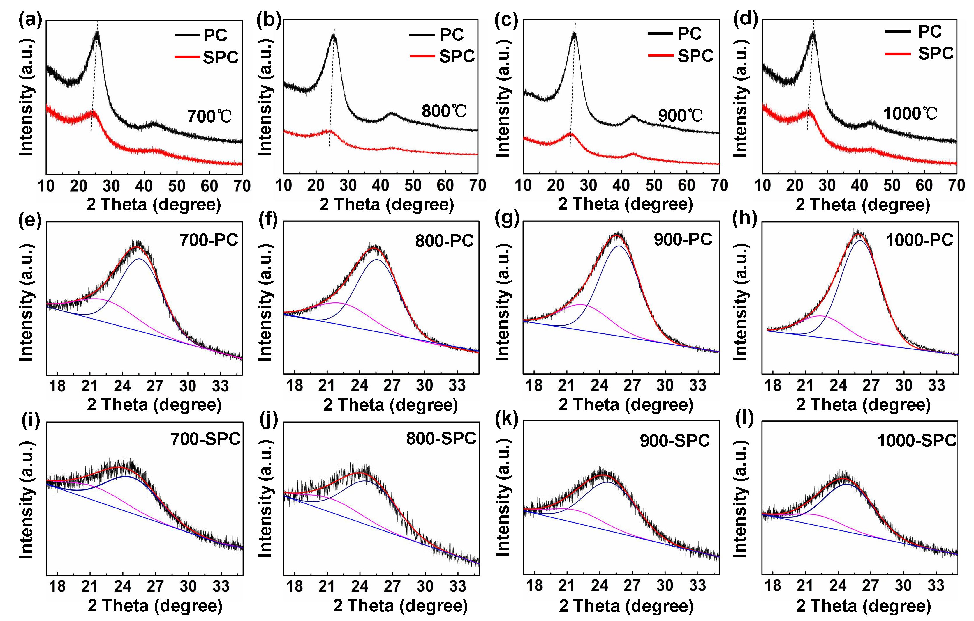
| 1000-PC | - | - | - | 22.59 | 0.394 | 19.80 | 26.01 | 0.343 | 80.20 | 0.353 | 1.95 |
| 900-PC | - | - | - | 22.57 | 0.394 | 25.84 | 25.82 | 0.345 | 74.16 | 0.358 | 1.85 |
| 800-PC | - | - | - | 22.50 | 0.395 | 28.50 | 25.77 | 0.346 | 71.50 | 0.360 | 1.80 |
| 700-PC | - | - | - | 22.42 | 0.396 | 29.14 | 25.67 | 0.347 | 70.86 | 0.361 | 1.71 |
| 1000-SPC | 22.11 | 0.402 | 17.75 | 25.01 | 0.356 | 82.25 | - | - | - | 0.364 | 1.58 |
| 900-SPC | 21.84 | 0.407 | 20.82 | 24.99 | 0.356 | 79.18 | - | - | - | 0.367 | 1.50 |
| 800-SPC | 21.43 | 0.415 | 24.31 | 24.95 | 0.357 | 75.69 | - | - | - | 0.371 | 1.44 |
| 700-SPC | 21.43 | 0.415 | 22.19 | 24.95 | 0.357 | 77.81 | - | - | - | 0.369 | 1.47 |
Publisher’s Note: MDPI stays neutral with regard to jurisdictional claims in published maps and institutional affiliations. |
© 2021 by the authors. Licensee MDPI, Basel, Switzerland. This article is an open access article distributed under the terms and conditions of the Creative Commons Attribution (CC BY) license (https://creativecommons.org/licenses/by/4.0/).
Share and Cite
Yin, R.; Wang, K.; Han, B.; Xu, G.; Li, L.; An, B.; Ju, D.; Chai, M.; Li, S.; Zhou, W. Structural Evaluation of Coal-Tar-Pitch-Based Carbon Materials and Their Na+ Storage Properties. Coatings 2021, 11, 948. https://doi.org/10.3390/coatings11080948
Yin R, Wang K, Han B, Xu G, Li L, An B, Ju D, Chai M, Li S, Zhou W. Structural Evaluation of Coal-Tar-Pitch-Based Carbon Materials and Their Na+ Storage Properties. Coatings. 2021; 11(8):948. https://doi.org/10.3390/coatings11080948
Chicago/Turabian StyleYin, Ruilin, Kun Wang, Beibei Han, Guiying Xu, Lixiang Li, Baigang An, Dongying Ju, Maorong Chai, Songnan Li, and Weimin Zhou. 2021. "Structural Evaluation of Coal-Tar-Pitch-Based Carbon Materials and Their Na+ Storage Properties" Coatings 11, no. 8: 948. https://doi.org/10.3390/coatings11080948
APA StyleYin, R., Wang, K., Han, B., Xu, G., Li, L., An, B., Ju, D., Chai, M., Li, S., & Zhou, W. (2021). Structural Evaluation of Coal-Tar-Pitch-Based Carbon Materials and Their Na+ Storage Properties. Coatings, 11(8), 948. https://doi.org/10.3390/coatings11080948