Review

The Protection, Challenge, and Prospect of Anti-Oxidation Coating on the Surface of Niobium Alloy

1
School of Metallurgical Engineering, Anhui University of Technology, Maanshan 243002, China
2
School of Civil Engineering and Architecture, Anhui University of Technology, Maanshan 243002, China
*
Author to whom correspondence should be addressed.
Coatings 2021, 11(7), 742; https://doi.org/10.3390/coatings11070742
Submission received: 25 May 2021 / Revised: 19 June 2021 / Accepted: 20 June 2021 / Published: 22 June 2021

Abstract

:
Niobium (Nb)-based alloys have been extensively used in the aerospace field owing to their excellent high-temperature mechanical properties. However, the inferior oxidation resistance severely limits the application of Nb-based alloys in a high-temperature, oxygen-enriched environment. Related scholars have extensively studied the oxidation protection of niobium alloy and pointed out that surface coating technology is ideal for solving this problem. Based on the different preparation methods of Nb-based alloys’ surface coatings, this article summarizes the relevant research of domestic and foreign scholars in the past 30 years, including the slurry sintering method (SS), suspension plasma spraying method (SPS), and halide activated pack cementation method (HAPC), etc. The growth mechanism and micromorphology of the coatings access by different preparation methods are evaluated. In addition, the advantages and disadvantages of various coating oxidation characteristics and coating preparation approaches are summarized. Finally, the coating’s oxidation behavior and failure mechanism are summarized and analyzed, aiming to provide valuable research references in related fields.

1. Introduction

With the human need for space exploration, the development of hypersonic vehicles has attracted wide attention worldwide [1,2]. Due to the nature of long-term hypersonic cruises and the flight of hypersonic aircraft back and forth between the atmosphere and atmospheric reentry [3], the aircraft must face extremely harsh environments, producing high dynamic pressure and aerodynamic heating effects [4,5]. The high-temperature structural materials need to withstand extreme thermal and mechanical loads [6], resulting in large temperature gradients and thermal stresses inside the material, thereby significantly reducing the cycle life of the components. Especially critical parts or components include aircraft nose cones, sharp leading edges, nozzle openings, hot ends of engines [7], etc. Accordingly, the thermal development and high-temperature oxidation resistance of high-temperature structural materials are increasingly required. Traditional steel materials, aluminum alloys, and titanium alloys can no longer meet the extreme environmental requirements of hypersonic aircraft [8]. Niobium and its alloys have become a critical applicant material for high-temperature structural parts in the aerospace and nuclear industries due to their high melting point [9], moderate density, excellent high-temperature strength, and good processability. Niobium-based alloys are expected to replace nickel-based materials and become critical structural materials in the aerospace field by the end of the 21st century [10,11]. Nonetheless, the oxidation resistance of niobium-based alloys is lacking [12], and severe pulverization will occur when exposed to air above 500 °C for a short time, severely restricting its application in high-temperature, oxygen-rich environments. At present, the commonly used methods to inhibit the occurrence of this kind of oxidation include alloying and surface coating technology [13]. Although alloying can improve the corrosion resistance of niobium-based alloys in high temperature and oxygen-enriched environments to a certain extent, this measure often seriously affects the physical properties of the base alloy itself. Surface coating technology is the most effective method for enhancing the oxidation resistance of niobium-based alloys while ensuring the substrate’s physical properties [13]. The arrangement of high-temperature, oxidation-resistant defensive coatings on the surface of niobium alloys has developed into a current research hotspot.
At present, there are many reports on the surface coating and oxidation protection of niobium and its alloys, but there are few studies on the growth mechanism and oxidation behavior of the surface coating. This article reviews the main preparation methods of niobium and its alloy surface coatings in recent years (such as the slurry sintering method (SS), suspension plasma spraying method (SPS), halide activated filling cementing method (HAPC), etc.). The latest research status of high-temperature, oxidation-resistant coatings on niobium-based alloys is discussed, and the advantages and disadvantages of various preparation methods are analyzed and summarized. The microscopic morphology, phase composition, and oxidation resistance of coatings prepared by different methods are compared and analyzed. The growth mechanism and oxidation behavior of various coatings are analyzed and summarized. At the same time, the future development direction of niobium and its alloy surface coatings is put forward with the purpose of adding valuable summaries for researchers on this ground.

2. Anti-Oxidation Coating on Niobium Alloys

The comprehensive properties of niobium alloy surface coatings are different due to the different preparation methods. In the following summary, different methods for preparing niobium alloy surface coatings will be described in detail, and the oxidation resistance performance of coatings prepared by different methods will be comprehensively compared.

2.1. Slurry Sintering Method

The slurry sintering method is the most commonly used coating preparation method on the surface of niobium alloys, and the process flow is shown in Figure 1. Firstly, the coating slurry is uniformly mixed with the components of the coating and the binder in proportion, to prepare the coating slurry [14,15], and the slurry is applied to the surface of the substrate by brushing, dipping, or spraying. Then it is solidified by pressurization and heating, and sintered in a vacuum or atmosphere furnace. Finally, a coating is formed on the face of the substrate. The process conditions, composition thickness [16], and the oxidation characteristics of the SS coatings on Nb-based alloys are summarized in Table 1. It can be perceived that the thickness of SS coatings was between 150 and 300 μm under the sintering temperature of 1200 to 1500 °C for 1–4 h in a vacuum or Ar atmosphere.
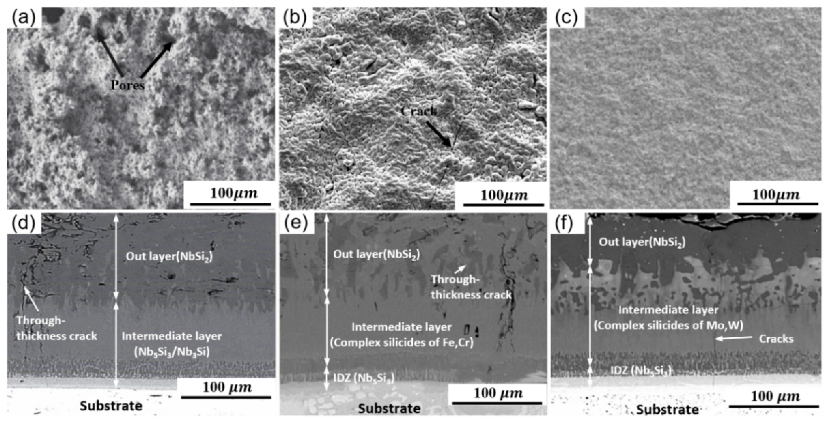
The typical surface and corresponding cross-sectional morphologies of SS coatings are shown in Figure 2. It can be noticed that the coating surface was relatively rough with dozens of holes and cracks. This was caused by the considerable particle size of the mixture, uneven mixing, and volatilization of the solvent and binder during the sintering process, as shown in Figure 2a,b. It is worth noting that Xiao et al. used smaller material particles for sintering and obtained a lower surface roughness, and the coating surface was relatively uniform and dense without apparent defects, as shown in Figure 2c. It can be observed from the cross-sectional images that the coating consisted of the outermost layer (NbSi2), the intermediate layer, and the internal interdiffusion layer (IZD). In addition, as there was a mismatch of thermal expansion coefficient between the substrate and the coating during the sintering process, a small number of longitudinal cracks were observed inside the coating [22]. However, the IZD area, where the coating and the substrate were connected, was heavy and uniform, revealing that an excellent metallurgical bond was achieved between the coating and the substrate [23], as shown in Figure 2d–f. Han et al. [24] systematically explained the delamination phenomenon of such coatings. They believed that the growth process of the coating was firstly combined by chemical adsorption and physical adsorption, and then polar groups and substrates diffused between them at high temperatures. Finally, a firm and dense interwoven network coating layer was formed at the interface.
Relevant scholars have researched the oxidation resistance of the coating. After oxidation in the series of 1200–1700 °C for 2–25 h, the mass transition per unit area of the coating was within 10 mg·cm−2, as shown in Table 1. The typical surface and cross-section microstructures of oxidized coatings are shown in Figure 3. It can be perceived that an oxide layer was formed on the oxidized coating surface, and the oxide layer consisted of SiO2 and Nb2O5. Compared with before oxidation, the coating surface was relatively smooth at the initial oxidation stage [25]. This was owing to the formation of SiO2 with a certain fluidity during the oxidation process, which filled up weaknesses such as cracks and gaps on the coating surface, to a certain extent. The inner coating was quite dense without apparent defects [26], as shown in Figure 3b,e. As the oxidation reaction progressed, the thickness of the oxide layer grew gradually. Several longitudinal cracks throughout the coating to the substrate were observed at the coating cross-section. This was caused by the large amount of volatile NbO2 produced during the oxidation process, as shown in Figure 3c. At the same time, a large number of longitudinal cracks throughout the entire cross-section were observed in the coating, and the same composition as the oxide layer was detected in this area, which shows that the coating could no longer provide adequate protection for the substrate, as shown in Figure 3f. Thermal diffusion referred to the spontaneous transition of matter to an equilibrium state in a high temperature and closed environment, significantly affected by temperature. Due to the principle of thermal diffusion [27], the thickness of the interface layer gradually increased throughout the process, as shown in Figure 3d–f.

2.2. Thermal Spraying Method

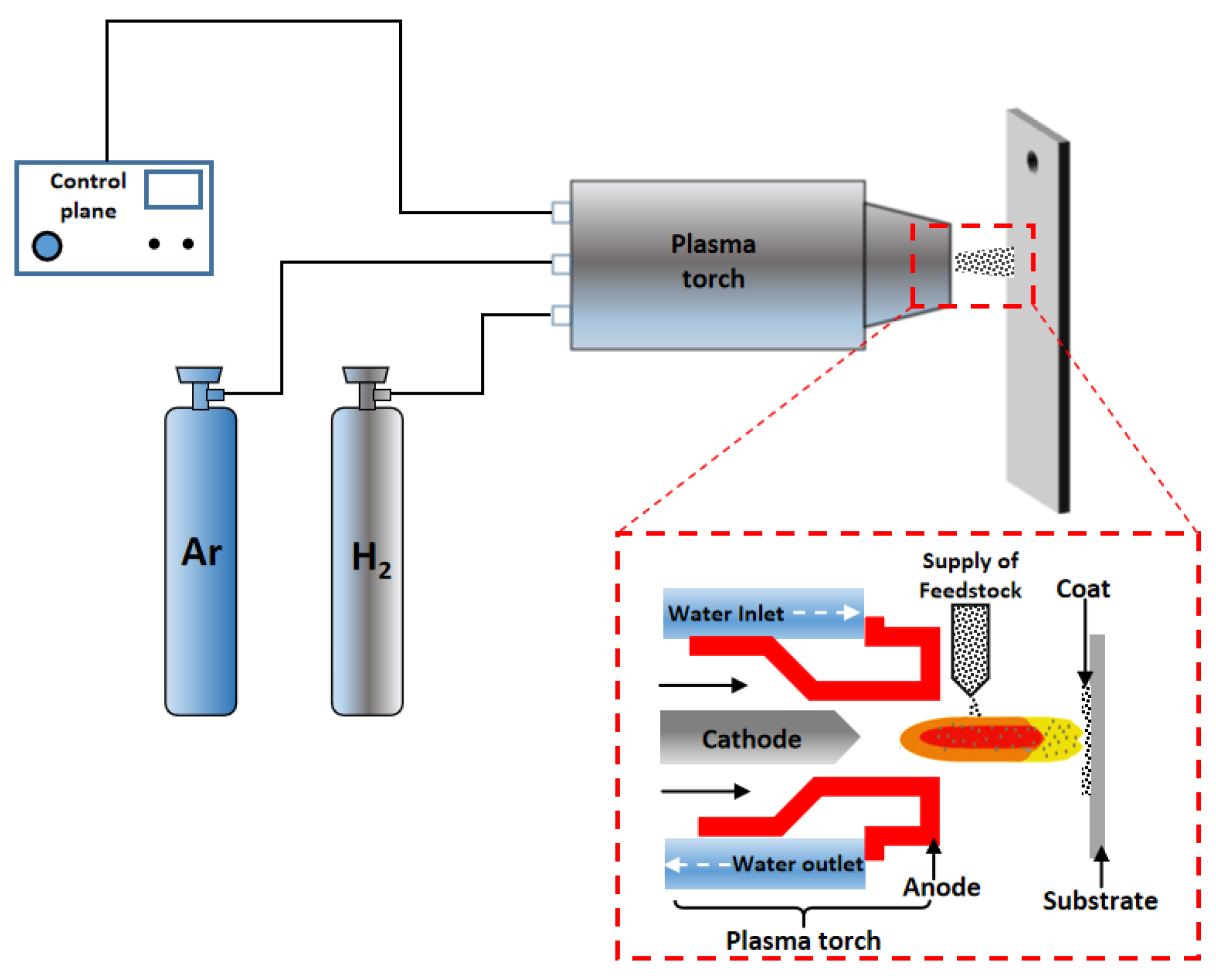
Thermal spraying is also called sputtering technology. Its principle is to spray molten or semi-molten materials on the surface of the substrate to form a coating through high-speed airflow [28,29]. Due to its high surface coating material, short spraying time, and positive bonding performance between the coating and substrate, it is considered one of the coating preparation technologies with the most development potential [30]. The most typical atmospheric plasma spraying (SPS) coating preparation process is shown in Figure 4. Table 2 summarizes the preparation process, coating structure, and oxidation resistance of SPS coatings on the surface of niobium-based alloys. It can be seen that MoSi2 has been favored by more researchers as the primary spray material [31,32]. This is mainly attributed to its high melting point, good thermal stability, and excellent high temperature creep resistance, which will make the material have a higher melting temperature and longer cooling time when sprayed on the substrate, and significantly improve the bonding strength between the substrate and coating particles. In addition, controlling the material size, carrier gas flow, spray distance, and other parameters will substantially impact the coating quality [33,34].
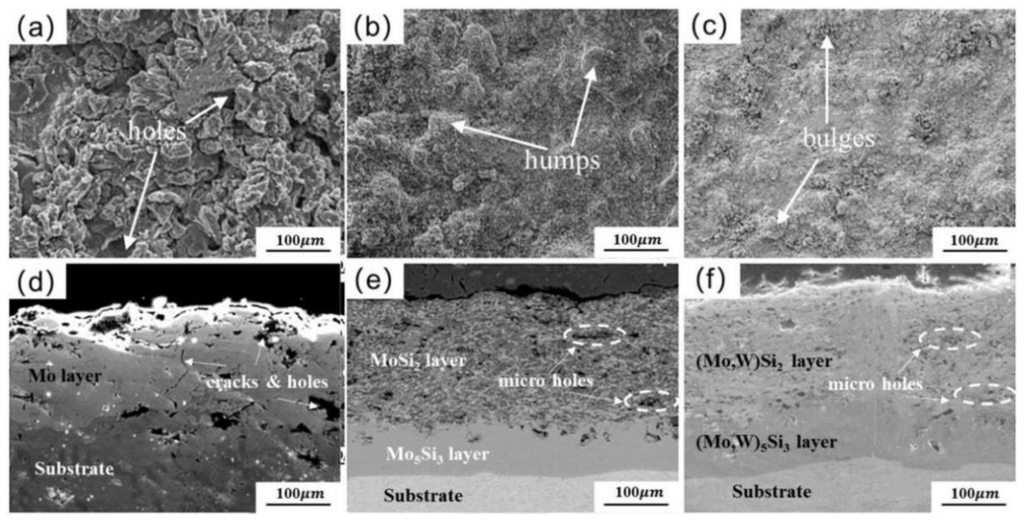
The SEM images of typical SPS coatings are listed in Figure 5. The average surface roughness (Ra) and porosity of the sprayed Mo coating were the same [35,36]. At the same time, apparent holes and cracks were observed at the cross-sectional coating, as shown in Figure 5a,d. However, with the introduction of other phases such as mullite and WSi2 in the spray material, the surface morphology was significantly improved, and the particle morphology was significantly eased. This was due to the vacancy complementation of the multi-element materials during the spraying process and the self-balance of the thermal conductivity and thermal expansion coefficient during the bonding process, as presented in Figure 5b,c. In addition, a continuous and uniform transition layer was observed between the coating and the substrate, indicating that a positive metallurgical bond was achieved betwixt the substrates and coating, as presented in Figure 5e,f. The author believes that the addition of mullite fills the holes during the spraying process, which can optimize the coating structure, and improves the coating density [37]. The addition of WSi2 can combine with MoSi2 to form (W, Mo)Si2 and (W, Mo)5Si3, which effectively inhibits the diffusion of Si elements, maintains the coating morphology, and relieves the internal coating caused by the mismatched thermal expansion coefficients defect.
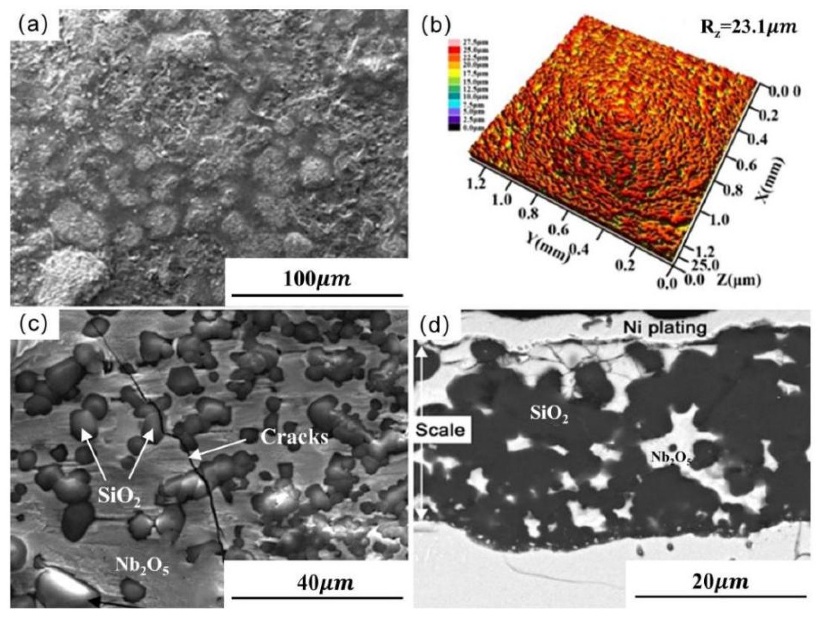
The researchers have studied the oxidation behavior of SPS coatings on Nb-based alloys, as presented in Table 2. The service life of coatings can reach tens to hundreds of hours in an oxidizing environment from 1200 to 1500 °C. The typical SEM of the oxidized coating is shown in Figure 6. It can be perceived that the large oxide particles appeared on the coating surface after cyclic oxidation at 1500 °C for 43 h. The laser scanning confocal microscopy (LSCM) results show that the Ra of oxidized coating was 23.1 μm, and the main components were SiO2 and Nb2O5 [38]. Moreover, a large number of holes and cracks were observed at the surface, as shown in Figure 6a–c. This was due to surface defects providing channels for the diffusion of oxygen atoms, resulting in excessive oxidation and expansion inside the coating. Meanwhile, the cyclic thermal shock further aggravated the peeling of the outer oxide protective layer from the inner substrate layer. The cross-sectional image shows that the inside of the oxide layer was very loose with a thickness between 20 to 30 μm, and there was a phenomenon of shedding in its local area, as presented in Figure 6d. However, the mass change of the Mo-MoSi2 coating [39] prepared by Zhang et al. after being oxidized at 1500 °C for 140 h was only −2.77 mg·cm−2. This is because the addition of mullite inhibits the crystallization of SiO2, improves its fluidity, and promotes the formation of a continuous and dense oxide film on the coating surface [40,41].
Table 2. Summary for preparation and oxidation resistance of SPS coatings on Nb-based alloys.
SubstrateMaterial Composition
(wt.%)
Process ConditionsCoating Composition
and Thickness
(μm)
Oxidation SystemOxidation ProductsQuality Change
(mg/cm2)
References
Spray Distance
(mm)
Spray Rate
(g/min)
Outer LayerInner Layer
Nb52110mullite-90MoSi210020h-MoSi2
t-MoSi2
t-WSi2
(150)
Mo5Si3
W5Si3
NbSi2
(50)
1500 °C
500 h
SiO24.41[42]
Nb521MoSi210020t-MoSi2
h-MoSi2
(155)
Mo5Si3
Mo
(45)
1500 °C
140 h
SiO221.38[43]
10mullite-90MoSi2Mullite
SiO2
−2.77
30mullite-70MoSi2−4.06
Nb521MoSi210025b-MoSi2
(98)
Mo5Si3
(23)
1200 °C
94 h
MoSi2[44]
Nb-WMoSi29020h-MoSi2
t-MoSi2
SiO2
(170)
Mo5Si3
(34)
1500 °C
43 h
SiO25.31[45]
Nb-Si-TiMo-45Si-45Al9025Mo(Si,Al)2
(100)
Mo5(Si,Al)3
(25)
1250 °C
100 h
SiO2
Al2O3
8.24[46]
Nb-Si-Ti2NaF-34Si-B-63Al2O310025MoSi2
(72)
Mo
Mo5Si3
(55)
1250 °C
100 h
SiO2
Borosilicate glass cover
1.28[47]

2.3. Embedding Method

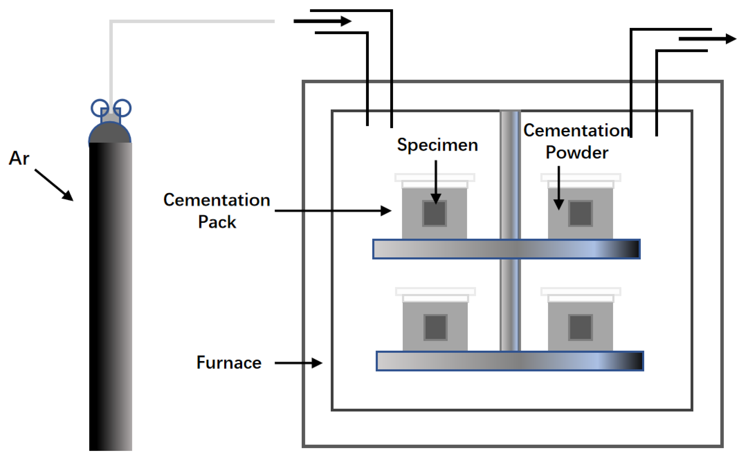
The embedding method is also known as HAPC, and the principle is to place the substrate in a permeation box containing the halide of the coating element and conduct heat treatment in a vacuum or under the condition of continuous inert gas [48,49]. The required coating is formed through vapor migration and reaction–diffusion; the process flowchart is shown in Figure 7. Because this method has the advantages of an uncomplicated process, significant coating efficiency, and freedom from the limitation of the shape of the workpiece, it is widely used in the oxidation protection of refractory metal surface coatings. The researchers conducted a systematic study on the composition and oxidation mechanism of the HAPC coating on the surface of Nb and its alloys, and the results are shown in Table 3. It can be noticed that if the temperature was in the range of 850–1300 °C for 5–25 h, a coating with a thickness of 40–200 μm was obtained. Qiao et al. [50] reported the significance of the growth law of coating crystals on its surface quality. The consequence is that, during the preparation of HAPC coatings, the contact interface between the substrate and the embedding agent undergo chemical combination and diffusion reactions. When the diffusion rate is greater than the reaction rate, many crystal nuclei are formed on the face of the base metal per unit time, which will cause the surface of the base to form a fine and dense coating. Conversely, when the diffusion rate is less than the reaction rate, there are limited crystal nuclei formed on the surface of the base metal per unit time, the formed crystal grains are coarse, the solid phase accumulation is relatively loose, and the coating pore cracks are more severe [51]. The diffusion rate and reaction rate were closely related to the embedding temperature, which theoretically confirms the decisive influence of the embedding temperature. Further research shows that if the thickness of the outer layer of the coating is controlled to 80–100 µm and the inner layer is controlled to 5–20 µm, the resulting coating is denser, with a porosity of about 5–15%.
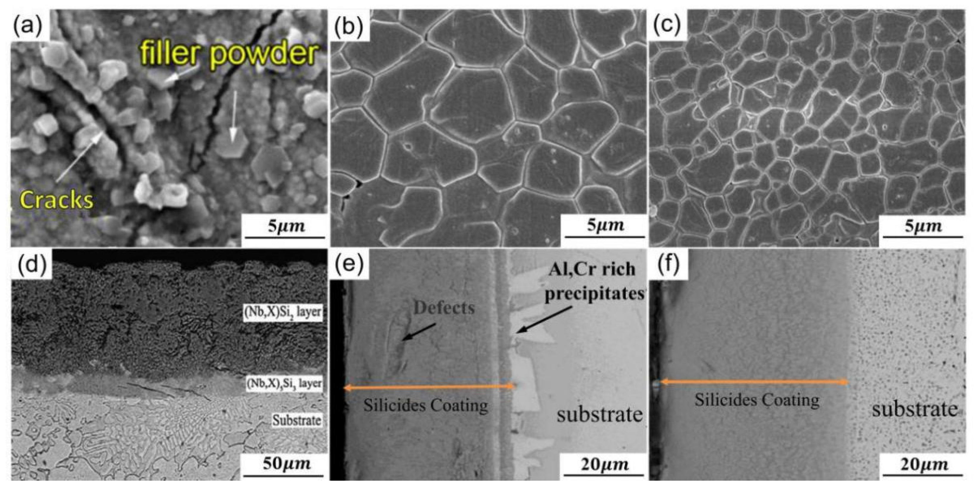
The typical SEM of HAPC coatings on Nb-based alloys is shown in Figure 8. It can be perceived that the Ra of the Nb-Si-Mo coating [58] was relatively high, and apparent cracks and large granular filler powder were observed at the facial. The internal porosity of the coating was relatively high, consisting of (Nb, X)5Si3 inner layer and (Nb, X)Si2 outer layer, and apparent cracks were observed at the interface layer, owing to the varying grain size of the embedded material [59] and the difference in thermal expansion coefficient between the substrate and the combined coating, as shown in Figure 8a,d. In order to optimize the coating structure, Majumdar et al. prepared a Ge/Ge-Y modified NbSi2 coating on the Nb substrate. It can be perceived that the surface of the Ge modified coating was relatively flat and smooth [60], but a small amount of pore was observed at the grain boundary, as shown in Figure 8b. The interior coating was relatively uniform, but there were still apparent defects. In addition, a large amount of Al and Cr-rich regions were noticed at the junction of the coating and the substrate, as shown in Figure 8e. Compared with the single-element Ge modified coating, the surface grains of the Ge-Y modified silicide coating after adding Y were smaller, and the average grain size was only 2 to 3 μm, as shown in Figure 8c. It is worth noting that the coating inside was very uniform and dense without any apparent defects [61], and the overall thickness was about 50 μm, as shown in Figure 8f. This is because the addition of the Y element takes advantage of the release of thermal stress and the filling of vacant defects so that the surface grains of the coating are significantly refined, and the gaps between the grains are significantly reduced.
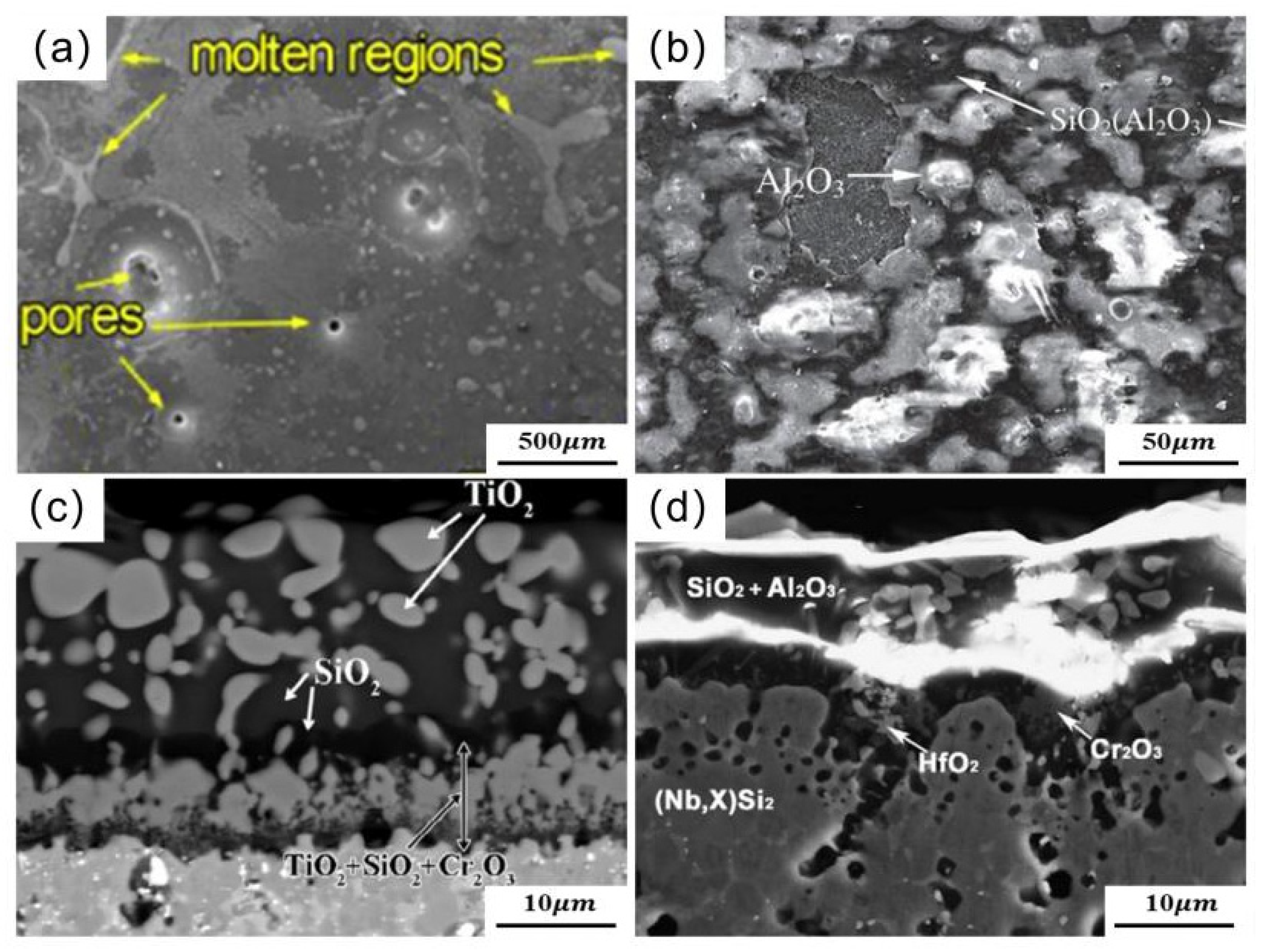
Related researchers have tested the oxidation resistance of HAPC coatings, as shown in Table 3. It can be noticed that the mass gain of the coating was only 0.4–13.1 mg·cm−2 after being oxidized at 1000–1250 °C for 17–650 h. Typical SEM of oxidized coating is shown in Figure 9. Overall, the oxidized Nb-Si-Ti coating surface was smoother, covering a layer of molten oxide film, but a few holes were still observed [62]. The author believes that this is related to the higher surface roughness of the coating before oxidation, resulting in uneven oxidation and the volatilization of Nb2O5 during the oxidation process, as shown in Figure 9a. The oxidation results show that the main component of the oxide film was SiO2-TiO2, and the thickness was about 20 μm. In addition, a small amount of Cr2O3 was also observed at the bottom of the oxide layer [63], as presented in Figure 9c. However, the oxidized (Nb, X)Si2 coating surface was very rough, and a large number of oxide particles mainly composed of SiO2-Al2O3 were observed, as shown in Figure 9b. A large number of holes and longitudinal cracks across the entire cross-section appeared in the coating. At the same time, partial areas of the oxide layer appeared to fall off [64]. It is worth emphasizing that an extended layer of Cr2O3 was observed betwixt the oxide layer and the internal coating, which relieved the further oxidation of the coating to a certain extent, as shown in Figure 9d.

2.4. Other Methods

By analyzing the advantages and disadvantages of the coating preparation process, related scholars appropriately combined different methods to make up for each other’s advantages and disadvantages, thereby obtaining a composite coating with superior oxidation resistance [65,66]. Common combination categories, process conditions, coating composition, thickness, and oxidation characteristics are shown in Table 4. It can be seen that the coating system was dominated by Mo-Si-X (B, Ce, etc.), which is related to the high thermal conductivity and good thermal stability of MoSi2.The addition of elements such as B and Ce can further optimize the coating structure and improve its oxidation resistance at high temperatures [67]. The thickness of the coating prepared by the two-step process was 55 to 160 μm. The outer layer mainly consisted of high-priced metal and high silicide, such as MoSi2. Due to the difference in the concentration of internal and external elements, the inner layer was mostly (Nb, X)5Si3 and (Nb, X)3Si. The typical coating surface and the corresponding cross-sectional morphology are shown in Figure 10. Since most of the later steps of this kind of method are HAPC, the coating surface exhibited a relatively high toughness, and a large amount of granular embedded powder was observed to adhere, as shown in Figure 10a,c. The main component of the coating layer was a mixture of MoSi2 and the second phase was loosely bonded and had many holes and cracks [68,69]. The inner layer mainly consisted of Nb-based metal silicide; its cross-sectional morphology was good, and the structure was dense and uniform. This shows that the coating and the substrate achieved good metallurgical bonding, as shown in Figure 10b,d. This type of coating preparation method realizes the diffusion and filling of the outer layer components to the inner layer components through the latter process so that the structure of the inner coating is further strengthened, and the use performance of the coating is significantly improved. In addition, technologies such as laser cladding technology (LCT), physical vapor deposition (PVD), and hot-dipped silicon (HDS) [70] have also been favored by related scholars in the preparation of Nb surface anti-oxidation coatings. Zhang et al. used HDS [71,72] technology to prepare a WSi2 coating [73,74] with nano-level roughness on the surface of W. The resulting coating facial was absolutely dense and uniform without defects such as holes, gaps [75], etc. This will help the technology apply the coating to the surface of Nb and its alloys, and provides a helpful reference for the preparation of anti-oxidation coating.
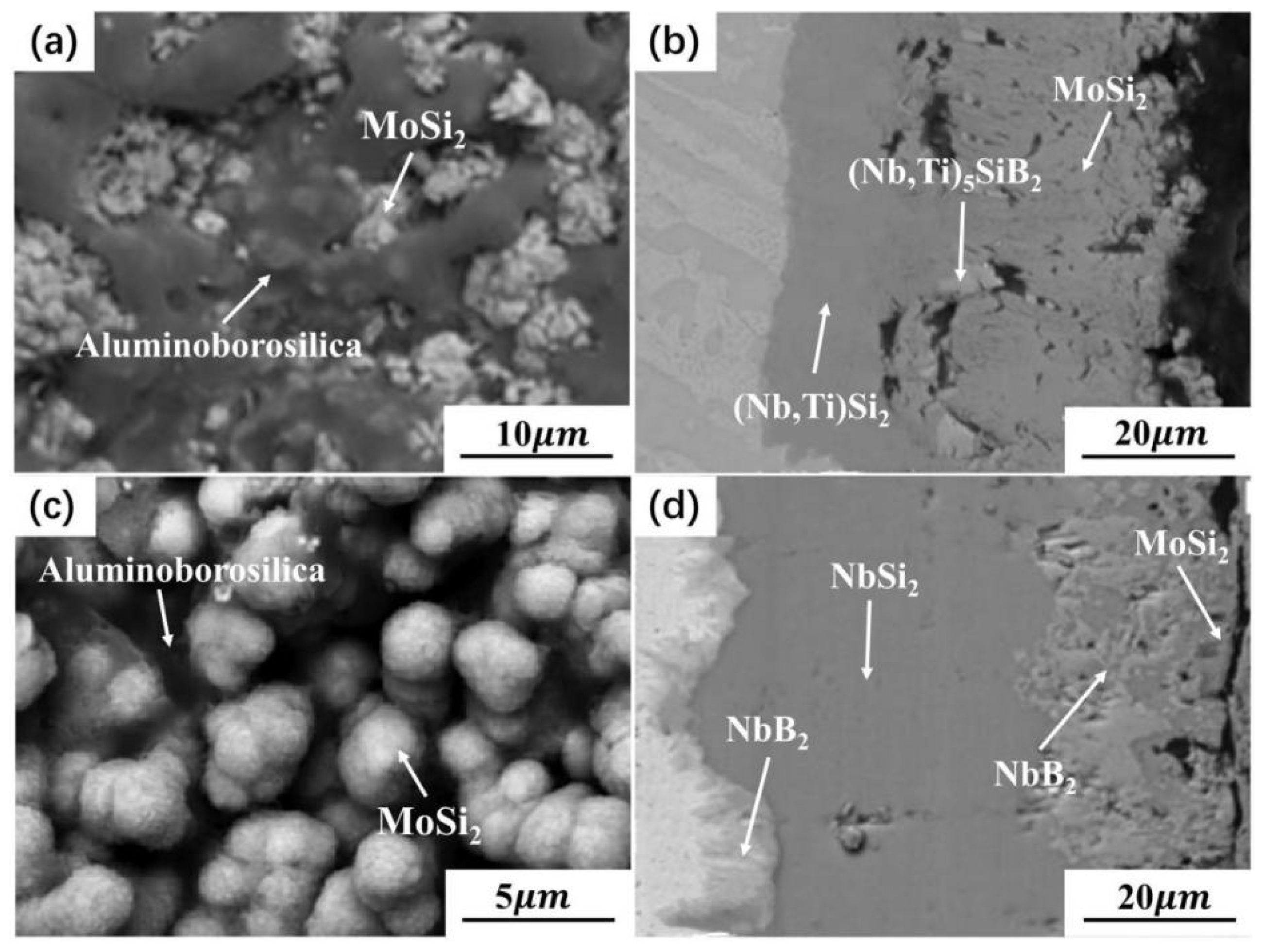
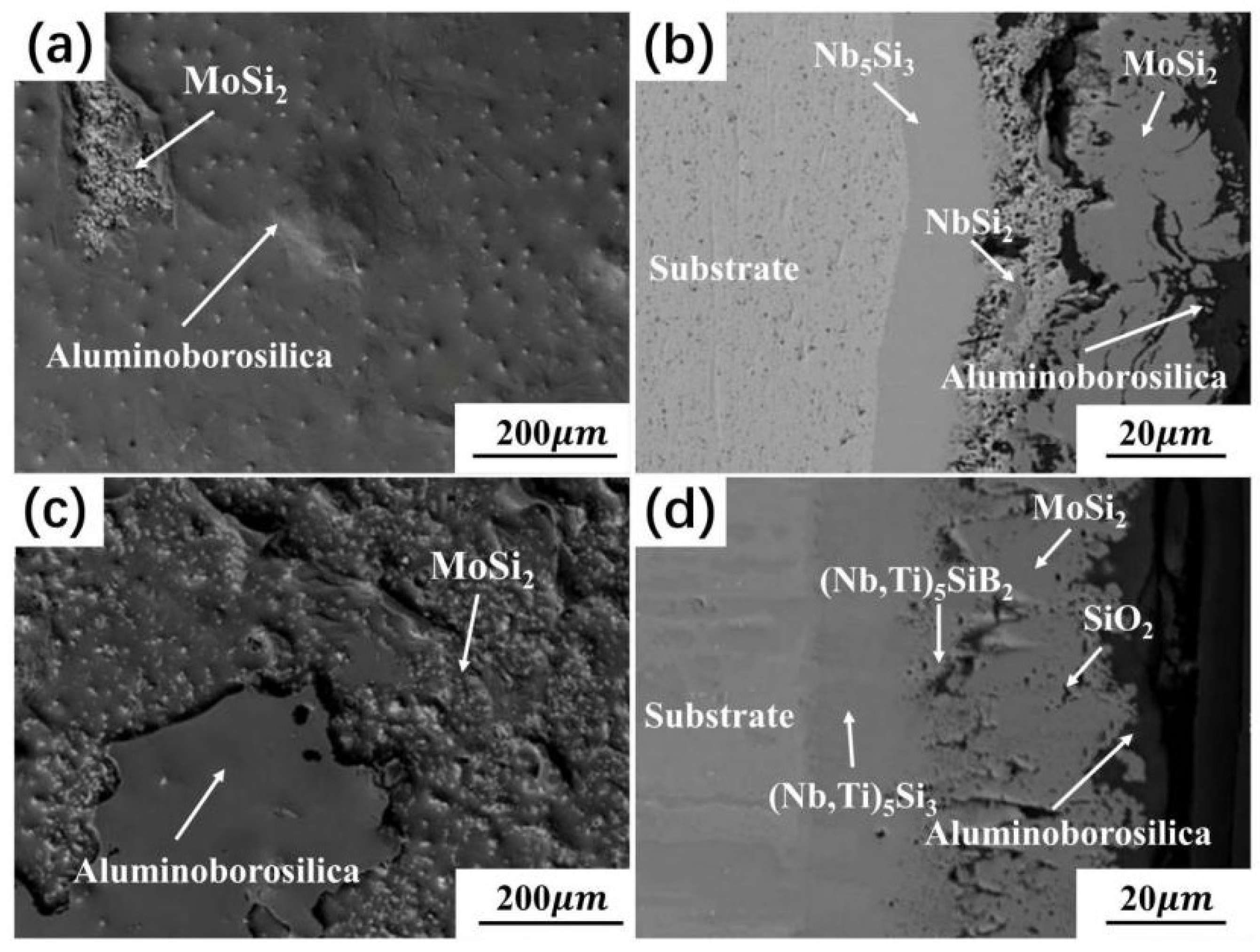
Figure 11 present the typical SEM of oxidized coatings prepared by the two-step approach. The mass loss per unit area of the coating was within 4 mg·cm−2 after being oxidized in the range of 1300–1600 °C for 24–100 h. The outward layer of the oxidized coating was approximately flat and smooth without apparent cracks and holes. This was due to the formation of aluminoborosilica with a certain fluidity during the oxidation process, filling in the surface defects [82], as shown in Figure 11a,c. MoSi2-SiO2 dominated the outer phase of the oxidized coating. Due to original defects and continuous consumption during the oxidation process, the partial area of the oxide layer fell off, showing discontinuity and inhomogeneity [83]. However, the inner layer organization of the coating was still dense and compact without apparent flaw, and the transition layer of (Nb, X)5Si3 and NbB2 was observed to grow inward at the interface between it and the substrate, as shown in Figure 11b,d.

3. Oxidation Mechanism and Failure Behavior of Coating

According to the summary of the oxidation characteristics of Nb alloys surface coatings, the oxidation behavior and failure mechanism are summarized, as shown in Figure 12. It can be noticed that oxidation can be divided into two stages. The inner and outer layers of the coating are composed of the Nb5Si3 layer and NbSi2 layer, respectively, as shown in Figure 12a. In the initial stage of oxidation, the oxygen-philic compounds on the coating surface are rapidly oxidized. The oxidation reaction is more severe at weak areas such as cracks, gaps, etc., and the generated oxides such as Nb2O5 and SiO2 are transformed into defects, start to grow, and gradually spread to the entire surface. As the reaction progresses, Nb2O5, NbO2, etc., gradually volatilize, leaving many holes on the surface. In addition, due to the release of thermal stress and the mismatch of thermal expansion coefficients between systems, many cracks sprout on the surface of the coating. At the same time, the addition of some modifying elements (X) improves the fluidity of SiO2, fills up these defects to a certain extent, and forms an Nb2O5-SiO2-X2O3 protective film system on its surface, as shown in Figure 12b. At last, the oxide layer gradually thickens, the NbSi2 layer as the central part of the coating is gradually consumed, and the self-healing ability of the coating gradually deteriorates. However, the Nb5Si3 layer with poor oxidation resistance gradually becomes thicker. With the oxidation process, the low oxidation resistance Nb5Si3 layer is gradually destroyed, resulting in the oxidation failure of the coating, and a large number of holes and cracks are observed, as shown in Figure 12c.

4. Conclusions and Prospects

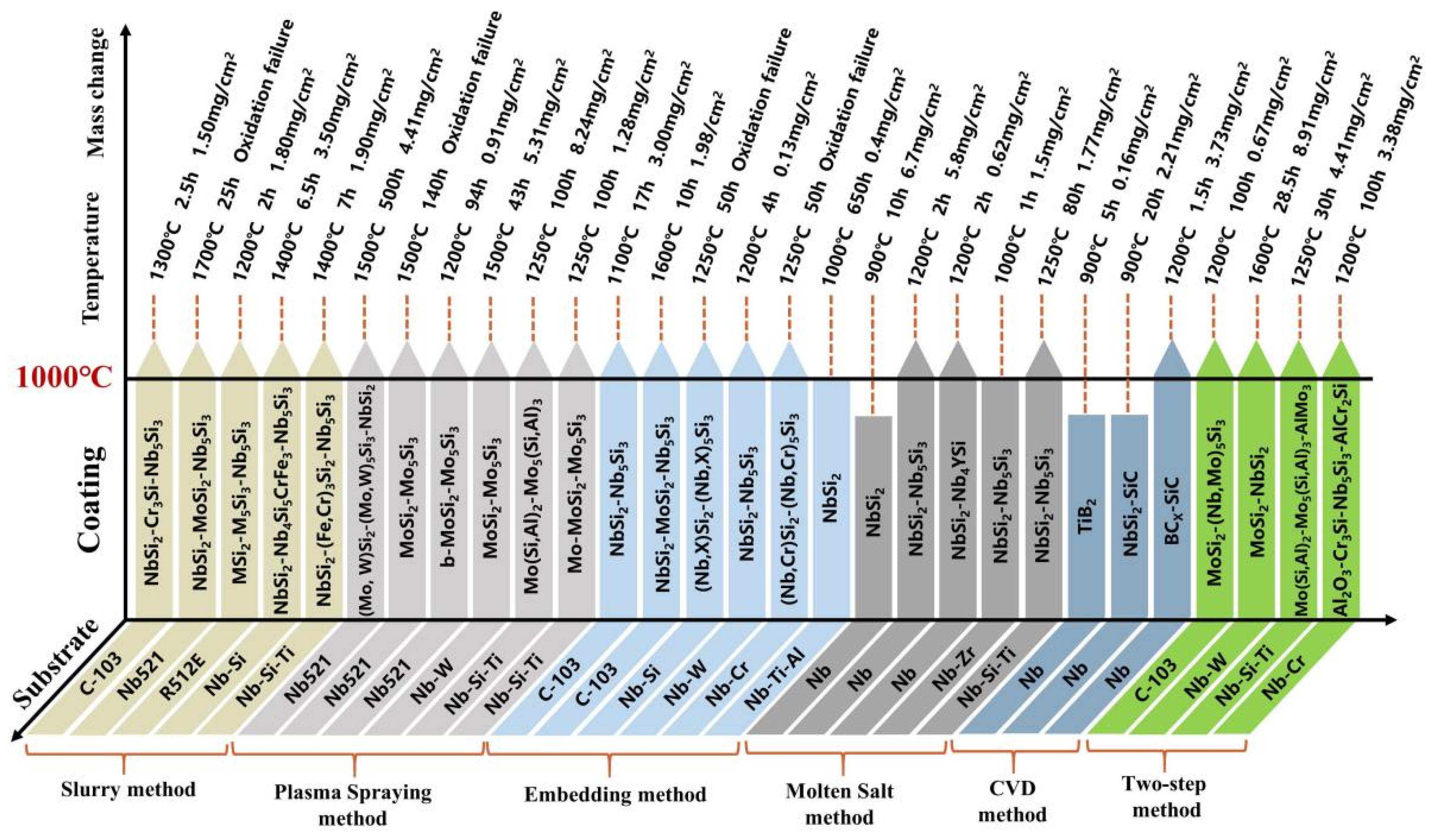
In this work, the preparation methods of anti-oxidation coatings on Nb-based alloys are reviewed, and the structure and anti-oxidation performance of coatings obtained by different methods are summarized, as shown in Figure 13. Overall, the high-temperature oxidation resistance of Nb-based alloys has been significantly enhanced by surface coating technology. Through in-depth comparison and analysis of various methods, it can be known that the volatilization of solvents and cement, and the uneven particle size of the mixture during the sintering process, result in poor surface quality and high porosity of the coating prepared by SS. Although the two processes of HAPC and CVD have no volatilization phenomenon and are not limited by the shape of the substrate, their lower deposition temperature makes the growth of the coating slower, and the preparation cycle is longer. In contrast, due to its high diffusion temperature, SPS can deposit coatings of tens to hundreds of microns in a short time. However, due to the uneven melting of the spray paint and a small amount of gas during the spraying process, the porosity of the coating is higher, and the bond with the substrate is poor. In addition, although the two-step coating has a relatively excellent structure, its process is complicated, and the coating preparation efficiency is low. As a new coating preparation process, HDS technology dominates due to short deposition time, high coating preparation productivity, smooth and dense coating surface, etc., and it is expected to protect Nb-based alloys at high temperatures.
Summarizing the anti-oxidation mechanism of the coating prepared by the above method, it can be found that the outer protective scale of the coating with better anti-oxidation performance is generally composed of SiO2 and other inert melt film shielding substances. However, inert molten films such as SiO2 are formed after oxidation tests, and the oxidation process is challenging to control. Therefore, in order to further improve the high-temperature oxidation resistance of the coating, some beneficial elements are usually added in an appropriate amount during the coating preparation process. Among them, the “selective oxidation type” alloy element X (X = A1, Cr, Mo, Ti, etc.) is added to make it preferentially combine with the O element to form an oxide during the high-temperature oxidation process, setting a dense isolated layer on the surface of the substrate. This blocks the inward diffusion of oxygen atoms, inhibits the formation of Nb2O5, and reduces the oxidation rate. The addition of element B and mullite can improve the fluidity of SiO2 and promote the formation of a uniform and thick oxide film on the coating surface. The addition of Y and Ce elements can refine the coating grains, optimize the coating structure, and significantly improve the strength of the coating at high temperatures so that it can maintain a good shape during the oxidation process. The addition of W and Ge can constrain the diffusion of Si elements into the substrate, slow down the generation of Nb5Si3 with poor oxidation resistance, and lengthen the oxidation service life of the coating. The introduction of a proper amount of mullite can fill the pores inside and on the coating surface, optimize the coating structure, increase the density of the coating, inhibit the recrystallization of SiO2, and promote the thick oxide film on the surface of the coating. In addition, optimizing the coating preparation process and structure can significantly reduce defects produced by thermal expansion coefficient mismatch between coating and substrate, which also plays a crucial role in improving the high-temperature oxidation resistance of the coating.

Author Contributions

Conceptualization, Y.Z.; methodology, Y.Z., X.Z. and T.F.; validation, Y.Z. and K.C.; formal analysis, J.W. and F.S.; investigation, L.Y., H.M. and T.F.; resources, Y.Z.; data curation, Y.Z., X.Z. and T.F.; writing—original draft preparation, Y.Z., X.Z. and T.F.; writing—review and editing, Y.Z., X.Z. and T.F.; visualization, X.Z. and T.F.; supervision, Y.Z.; project administration, Y.Z.; funding acquisition, Y.Z. All authors have read and agreed to the published version of the manuscript.

Funding

This research was funded by the National Natural Science Foundation (51604049).

Institutional Review Board Statement

Not applicable.

Informed Consent Statement

Not applicable.

Data Availability Statement

Not applicable.

Acknowledgments

The authors wish to acknowledge the contributions of associates and colleagues at Anhui University of Technology. The financial support of the National Natural Science Foundation.

Conflicts of Interest

The authors declare no conflict of interest.

References

  1. Subramanian, P.; Mendiratta, M.; Dimiduk, D. The development of Nb-based advanced intermetallic alloys for structural applications. JOM 1996, 48, 33–38. [Google Scholar] [CrossRef]
  2. Wadsworth, J.; Froes, F. Developments in metallic materials for aerospace applications. JOM 1989, 41, 12–19. [Google Scholar] [CrossRef]
  3. Zhu, Y.; Peng, W.; Xu, R.; Jiang, P. Review on active thermal protection and its heat transfer for airbreathing hypersonic vehicles. Chin. J. Aeronaut. 2018, 31, 1929–1953. [Google Scholar] [CrossRef]
  4. Ji, T.; Zhang, R.; Sunden, B.; Xie, G. Investigation on thermal performance of high temperature multilayer insulations for hypersonic vehicles under aerodynamic heating condition. Appl. Therm. Eng. 2014, 70, 957–965. [Google Scholar] [CrossRef]
  5. Jian, D.; Qiuru, Z. Key technologies for thermodynamic cycle of precooled engines: A review. Acta Astronaut. 2020, 177, 299–312. [Google Scholar] [CrossRef]
  6. Yuan, B.; Harvey, C.M.; Thomson, R.C.; Critchlow, G.W.; Wang, S. A new spallation mechanism of thermal barrier coatings on aero-engine turbine blades. Theor. Appl. Mech. Lett. 2018, 8, 7–11. [Google Scholar] [CrossRef]
  7. Prasad, V.S.; Baligidad, R.; Gokhale, A.A. Niobium and other high temperature refractory metals for aerospace applications. In Aerospace Materials and Material Technologies; Springer: Cham, Switzerland, 2017; pp. 267–288. [Google Scholar]
  8. Inouye, H. Niobium in high temperature applications. In Proceedings of the Niobium-Proceedings of the International Symposium; Metallurgical Society of AIME: Warrendale, PA, USA, 1984. [Google Scholar]
  9. Eckert, J. Niobium compounds and alloys. Int. J. Refract. Met. Hard Mater. 1993, 12, 335–340. [Google Scholar] [CrossRef]
  10. Wojcik, C.C. Processing, properties and applications of high-temperature niobium alloys. Mrs Online Proc. Libr. (OPL) 1993, 322, 519. [Google Scholar] [CrossRef]
  11. Wadsworth, J.; Nieh, T.; Stephens, J. Recent advances in aerospace refractory metal alloys. Int. Mater. Rev. 1988, 33, 131–150. [Google Scholar] [CrossRef]
  12. Zhang, S.; Li, X.; Zuo, J.; Qin, J.; Cheng, K.; Feng, Y.; Bao, W. Research progress on active thermal protection for hypersonic vehicles. Prog. Aerosp. Sci. 2020, 119, 100646. [Google Scholar] [CrossRef]
  13. Wojcik, C.C.; Chang, W. Thermomechanical processing and properties of niobium alloys. In Proceedings of the International Symposium on Niobium 2001, Orlando, FL, USA, 2–5 December 2001; pp. 163–173. [Google Scholar]
  14. Packer, C.M.; Perkins, R.A. Development of a fused slurry silicide coating for the protection of tantalum alloys. J. Less Common Met. 1974, 37, 361–378. [Google Scholar] [CrossRef]
  15. Streiff, R. Protection of materials by advanced high temperature coatings. J. Phys. IV 1993, 3, C9–C17. [Google Scholar] [CrossRef] [Green Version]
  16. Kumawat, M.K.; Alam, M.Z.; Kumar, A.; Gopinath, K.; Saha, S.; Singh, V.; Srinivas, V.; Das, D.K. Tensile behavior of a slurry Fe-Cr-Si coated Nb-alloy evaluated by Gleeble testing. Surf. Coat. Technol. 2018, 349, 695–706. [Google Scholar] [CrossRef]
  17. Alam, M.Z.; Sarin, S.; Kumawat, M.K.; Das, D.K. Microstructure and oxidation behaviour of Fe–Cr–silicide coating on a niobium alloy. Mater. Sci. Technol. 2016, 32, 1826–1837. [Google Scholar] [CrossRef]
  18. Novak, M.D.; Levi, C.G. Oxidation and Volatilization of Silicide Coatings for Refractory Niobium Alloys. In Proceedings of the ASME 2007 International Mechanical Engineering Congress and Exposition, Seattle, WA, USA, 11–15 November 2007; pp. 261–267. [Google Scholar]
  19. Pan, Y.; Guan, W.M. The hydrogenation mechanism of PtAl and IrAl thermal barrier coatings from first-principles investigations. Int. J. Hydrog. Energy 2020, 45, 20032–20041. [Google Scholar] [CrossRef]
  20. Geethasree, K.; Satya Prasad, V.V.; Brahma Raju, G.; Alam, M.Z. Cyclic oxidation behavior of Fe-Cr modified slurry silicide coated Nb-18.7Si alloyed with Ti and Zr. Corros. Sci. 2019, 148, 293–306. [Google Scholar] [CrossRef]
  21. Geethasree, K.; Alam, M.Z.; Raju, G.B.; Prasad, V.V.S. Microstructure and mechanical properties of uncoated Nb-18.7Si and Nb-18.7Si-5Ti alloys and their improved oxidation resistance after application of silicide coating. Mater. Today Proc. 2019, 15, 36–43. [Google Scholar] [CrossRef]
  22. Li, Y.; Lin, X.; Hu, Y.; Gao, X.; Yu, J.; Qian, M.; Dong, H.; Huang, W. Microstructure and isothermal oxidation behavior of Nb-Ti-Si-based alloy additively manufactured by powder-feeding laser directed energy deposition. Corros. Sci. 2020, 173, 108757. [Google Scholar] [CrossRef]
  23. Pan, Y.; Pu, D.L.; Yu, E.D. Structural, electronic, mechanical and thermodynamic properties of Cr–Si binary silicides from first-principles investigations. Vacuum 2021, 185, 110024. [Google Scholar] [CrossRef]
  24. Han, J.; Su, B.; Meng, J.; Zhang, A.; Wu, Y. Microstructure and composition evolution of a fused slurry silicide coating on MoNbTaTiW refractory high-entropy alloy in high-temperature oxidation environment. Materials 2020, 13, 3592. [Google Scholar] [CrossRef]
  25. Segura-Cedillo, I. Fused Metallic Slurry Coatings for Improving the Oxidation Resistance of Wrought Alloys. Ph.D. Thesis, The University of Manchester, Manchester, UK, 1 August 2011. [Google Scholar]
  26. Sankar, M.; Satya Prasad, V.V.; Baligidad, R.G.; Alam, M.Z.; Das, D.K.; Gokhale, A.A. Microstructure, oxidation resistance and tensile properties of silicide coated Nb-alloy C-103. Mater. Sci. Eng. A 2015, 645, 339–346. [Google Scholar] [CrossRef]
  27. Ji, P.F.; Li, B.; Chen, B.H.; Wang, F.; Ma, W.; Zhang, X.Y.; Ma, M.Z.; Liu, R.P. Effect of Nb addition on the stability and biological corrosion resistance of Ti-Zr alloy passivation films. Corros. Sci. 2020, 170, 108696. [Google Scholar] [CrossRef]
  28. Herman, H. Plasma-sprayed coatings. Sci. Am. 1988, 259, 112–117. [Google Scholar] [CrossRef]
  29. Fauchais, P. Understanding plasma spraying. J. Phys. D Appl. Phys. 2004, 37, R86. [Google Scholar] [CrossRef]
  30. Stöver, D.; Pracht, G.; Lehmann, H.; Dietrich, M.; Döring, J.-E.; Vaßen, R. New material concepts for the next generation of plasma-sprayed thermal barrier coatings. J. Therm. Spray Technol. 2004, 13, 76–83. [Google Scholar] [CrossRef]
  31. Zhang, Y.; Hussain, S.; Cui, K.; Fu, T.; Wang, J.; Javed, M.S.; Lv, Y.; Aslam, B. Microstructure and mechanical properties of MoSi2 coating deposited on Mo substrate by hot dipping processes. J. Nanoelectron. Optoelectron. 2019, 14, 1680–1685. [Google Scholar] [CrossRef]
  32. Pan, Y.; Yu, E. First-principles investigation of structural stability, mechanical and thermodynamic properties of Pt3Zr5 compounds. Phys. B Condens. Matter 2021, 611, 412936. [Google Scholar] [CrossRef]
  33. Odhiambo, J.G.; Li, W.; Zhao, Y.; Li, C. Porosity and its significance in plasma-sprayed coatings. Coatings 2019, 9, 460. [Google Scholar] [CrossRef] [Green Version]
  34. Hu, D.; Fu, Q.; Zhou, L.; Liu, B.; Sun, J. Crack development behavior in thermally sprayed anti-oxidation coating under repeated thermal-oxygen coupling environment. Ceram. Int. 2021, 47, 15328–15336. [Google Scholar] [CrossRef]
  35. Sun, J.; Li, T.; Zhang, G.-P. Effect of thermodynamically metastable components on mechanical and oxidation properties of the thermal-sprayed MoSi2 based composite coating. Corros. Sci. 2019, 155, 146–154. [Google Scholar] [CrossRef]
  36. Hou, Q.; Shao, W.; Li, M.; Zhou, C. Interdiffusion behavior of Mo-Si-B/Al2O3 composite coating on Nb-Si based alloy. Surf. Coat. Technol. 2020, 401, 126243. [Google Scholar] [CrossRef]
  37. Cui, K.; Zhang, Y.; Fu, T.; Wang, J.; Zhang, X. Toughening mechanism of mullite matrix composites: A Review. Coatings 2020, 10, 672. [Google Scholar] [CrossRef]
  38. Zheng, K.; Wang, Y.; Wang, R.; Wang, Y.; Cheng, F.; Ma, Y.; Hei, H.; Gao, J.; Zhou, B.; Wang, Y. Microstructure, oxidation behavior and adhesion of a CoNiCrAlTaY coating deposited on a high Nb-TiAl alloy by plasma surface metallizing technique. Vacuum 2020, 179, 109494. [Google Scholar] [CrossRef]
  39. Zhang, Y.; Li, Y.; Bai, C. Microstructure and oxidation behavior of Si–MoSi2 functionally graded coating on Mo substrate. Ceram. Int. 2017, 43, 6250–6256. [Google Scholar] [CrossRef]
  40. Hou, Q.; Li, M.; Shao, W.; Zhou, C. Oxidation and interdiffusion behavior of Mo-Si-B coating on Nb-Si based alloy prepared by spark plasma sintering. Corros. Sci. 2020, 169, 108638. [Google Scholar] [CrossRef]
  41. Hu, L.; Li, S.; Li, C.; Fu, G.; He, J.; Dong, Y.; Yang, Y.; Zhao, H.; Qin, Y.; Yin, F. Deposition and properties of plasma sprayed NiCrCoMo–TiC composite coatings. Mater. Chem. Phys. 2020, 254, 123502. [Google Scholar] [CrossRef]
  42. Zhang, G.; Sun, J.; Fu, Q. Microstructure and oxidation behavior of plasma sprayed WSi2-mullite-MoSi2 coating on niobium alloy at 1500 °C. Surf. Coat. Technol. 2020, 400, 126210. [Google Scholar] [CrossRef]
  43. Zhang, G.; Sun, J.; Fu, Q. Effect of mullite on the microstructure and oxidation behavior of thermal-sprayed MoSi2 coating at 1500 °C. Ceram. Int. 2020, 46, 10058–10066. [Google Scholar] [CrossRef]
  44. Sun, J.; Fu, Q.-G.; Huo, C.-X.; Li, T.; Wang, C.; Cheng, C.-Y.; Yang, G.-J.; Sun, J.-C. Oxidation response determined by multiphase-dependent melting degree of plasma sprayed MoSi2 on Nb-based alloy. J. Alloys Compd. 2018, 762, 922–932. [Google Scholar] [CrossRef]
  45. Pan, Y.; Yu, E.; Wang, D.; Deng, H. Sulfur vacancy enhances the electronic and optical properties of FeS2 as the high performance electrode material. J. Alloys Compd. 2021, 858, 157662. [Google Scholar] [CrossRef]
  46. Yao, D.; Gong, W.; Zhou, C. Development and oxidation resistance of air plasma sprayed Mo–Si–Al coating on an Nbss/Nb5Si3 in situ composite. Corros. Sci. 2010, 52, 2603–2611. [Google Scholar] [CrossRef]
  47. Wu, J.; Wang, W.; Zhou, C. Microstructure and oxidation resistance of Mo–Si–B coating on Nb based in situ composites. Corros. Sci. 2014, 87, 421–426. [Google Scholar] [CrossRef]
  48. Bianco, R.; Rapp, R.A. Pack cementation diffusion coatings. In Metallurgical and Ceramic Protective Coatings; Stern, K.H., Ed.; Springer: Berlin/Heidelberg, Germany, 1996; pp. 236–260. [Google Scholar]
  49. Mevrel, R.; Duret, C.; Pichoir, R. Pack cementation processes. Mater. Sci. Technol. 1986, 2, 201–206. [Google Scholar] [CrossRef]
  50. Goward, G.; Cannon, L. Pack cementation coatings for superalloys: A review of history, theory, and practice. J. Eng. Gas Turbines Power 1988, 110, 150–154. [Google Scholar] [CrossRef]
  51. Sun, J.; Li, T.; Zhang, G.-P.; Fu, Q.-G. Different oxidation protection mechanisms of HAPC silicide coating on niobium alloy over a large temperature range. J. Alloys Compd. 2019, 790, 1014–1022. [Google Scholar] [CrossRef]
  52. Alam, M.Z.; Rao, A.S.; Das, D.K. Microstructure and high temperature oxidation performance of silicide coating on Nb-based alloy C-103. Oxid. Met. 2010, 73, 513–530. [Google Scholar] [CrossRef]
  53. Zheng, H.; Xiong, L.; Luo, Q.; Lu, S. Development of multilayer oxidation resistant coatings on Cr–50Nb alloy. Appl. Surf. Sci. 2015, 359, 515–520. [Google Scholar] [CrossRef]
  54. Qiao, Y.; Li, M.; Guo, X. Development of silicide coatings over Nb–NbCr2 alloy and their oxidation behavior at 1250 °C. Surf. Coat. Technol. 2014, 258, 921–930. [Google Scholar] [CrossRef]
  55. Zhang, S.; Shi, X.; Sha, J. Oxidation behaviours of Nb–22Ti–15Si–2Al–2Hf–2V–(2, 14) Cr alloys with Al and Y modified silicide coatings prepared by pack cementation. Prog. Nat. Sci. Mater. Int. 2015, 25, 486–495. [Google Scholar] [CrossRef] [Green Version]
  56. Wang, W.; Zhou, C. Characterization of microstructure and oxidation resistance of Y and Ge modified silicide coating on Nb-Si based alloy. Corros. Sci. 2016, 110, 114–122. [Google Scholar] [CrossRef]
  57. Chaia, N.; Cury, P.; Rodrigues, G.; Coelho, G.; Nunes, C. Aluminide and silicide diffusion coatings by pack cementation for Nb-Ti-Al alloy. Surf. Coat. Technol. 2020, 389, 125675. [Google Scholar] [CrossRef]
  58. Yoon, J.K.; Kim, G.H.; Hong, K.T.; Doh, J.M.; Lee, J.K.; Lee, K.H.; Son, K.H. NbSi-2 Base Nanocomposite Coating and Manufacturing Method Thereof. U.S. Patent 20060029830A1, 29 December 2004. [Google Scholar]
  59. Xiao, L.-r.; Cai, Z.-g.; YI, D.-q.; Lei, Y.; Liu, H.-q.; Huang, D.-y. Morphology, structure and formation mechanism of silicide coating by pack cementation process. Trans. Nonferrous Met. Soc. China 2006, 16, s239–s244. [Google Scholar] [CrossRef]
  60. Chaliampalias, D.; Vourlias, G.; Pavlidou, E.; Skolianos, S.; Chrissafis, K.; Stergioudis, G. Comparative examination of the microstructure and high temperature oxidation performance of NiCrBSi flame sprayed and pack cementation coatings. Appl. Surf. Sci. 2009, 255, 3605–3612. [Google Scholar] [CrossRef]
  61. Majumdar, S.; Arya, A.; Sharma, I.; Suri, A.; Banerjee, S. Deposition of aluminide and silicide based protective coatings on niobium. Appl. Surf. Sci. 2010, 257, 635–640. [Google Scholar] [CrossRef]
  62. Qiao, Y.; Guo, X. Formation of Cr-modified silicide coatings on a Ti–Nb–Si based ultrahigh-temperature alloy by pack cementation process. Appl. Surf. Sci. 2010, 256, 7462–7471. [Google Scholar] [CrossRef]
  63. Cui, K.; Zhang, Y.; Fu, T.; Hussain, S.; Saad AlGarni, T.; Wang, J.; Zhang, X.; Ali, S. Effects of Cr2O3 content on microstructure and mechanical properties of Al2O3 matrix composites. Coatings 2021, 11, 234. [Google Scholar] [CrossRef]
  64. Sun, Z.; Tian, X.; Guo, X.; Yin, M.; Zhang, F.; Zhang, X. Oxidation resistance and mechanical characterization of silicide coatings on the Nb-18Ti-14Si-9Al alloy. Int. J. Refract. Met. Hard Mater. 2017, 69, 18–26. [Google Scholar] [CrossRef]
  65. Pu, R.; Sun, Y.; Xu, J.; Zhou, X.; Li, S.; Zhang, B.; Cai, Z.; Liu, S.; Zhao, X.; Xiao, L. Microstructure and properties of Mo-based double-layer MoSi2 thick coating by a new two-step method. Surf. Coat. Technol. 2020, 394, 125840. [Google Scholar] [CrossRef]
  66. Sun, J.; Fu, Q.-G.; Guo, L.-P.; Wang, L. Silicide coating fabricated by HAPC/SAPS combination to protect niobium alloy from oxidation. Acs Appl. Mater. Interfaces 2016, 8, 15838–15847. [Google Scholar] [CrossRef]
  67. Liu, L.; Zhang, H.; Lei, H.; Li, H.; Gong, J.; Sun, C. Influence of different coating structures on the oxidation resistance of MoSi2 coatings. Ceram. Int. 2020, 46, 5993–5997. [Google Scholar] [CrossRef]
  68. Liu, Y.; Shao, W.; Wang, C.; Zhou, C. Microstructure and oxidation behavior of Mo-Si-Al coating on Nb-based alloy. J. Alloy. Compd. 2018, 735, 2247–2255. [Google Scholar] [CrossRef]
  69. Majumdar, S.; Mishra, S.; Paul, B.; Kishor, J.; Mishra, P.; Chakravartty, J. Development of MoSi2 coating on Nb-1Zr-0.1 C alloy. Mater. Today Proc. 2016, 3, 3172–3177. [Google Scholar] [CrossRef]
  70. Zhang, Y.; Cui, K.; Fu, T.; Wang, J.; Shen, F.; Zhang, X.; Yu, L. Formation of MoSi2 and Si/MoSi2 coatings on TZM (Mo–0.5 Ti–0.1 Zr–0.02 C) alloy by hot dip silicon-plating method. Ceram. Int. 2021, in press. [Google Scholar]
  71. Zhang, Y.; Qie, J.; Cui, K.; Fu, T.; Fan, X.; Wang, J.; Zhang, X. Effect of hot dip silicon-plating temperature on microstructure characteristics of silicide coating on tungsten substrate. Ceram. Int. 2020, 46, 5223–5228. [Google Scholar] [CrossRef]
  72. Zhang, Y.; Zhao, J.; Li, J.; Lei, J.; Cheng, X. Effect of hot-dip siliconizing time on phase composition and microstructure of Mo–MoSi2 high temperature structural materials. Ceram. Int. 2019, 45, 5588–5593. [Google Scholar] [CrossRef]
  73. Zhang, Y.; Fu, T.; Cui, K.; Shen, F.; Wang, J.; Yu, L.; Mao, H. Evolution of surface morphology, roughness and texture of tungsten disilicide coatings on tungsten substrate. Vacuum 2021, 191, 110297. [Google Scholar] [CrossRef]
  74. Zhang, Y.; Cui, K.; Fu, T.; Wang, J.; Qie, J. Synthesis WSi2 coating on W substrate by HDS method with various deposition times. Appl. Surf. Sci. 2020, 511, 145551. [Google Scholar] [CrossRef]
  75. Zhang, Y.; Cui, K.; Gao, Q.; Hussain, S.; Lv, Y. Investigation of morphology and texture properties of WSi2 coatings on W substrate based on contact-mode AFM and EBSD. Surf. Coat. Technol. 2020, 396, 125966. [Google Scholar] [CrossRef]
  76. Lu–Steffes, O.J.; Su, L.; Jackson, D.M.; Perepezko, J.H. Mo–Si–B coating for improved oxidation resistance of niobium. Adv. Eng. Mater. 2015, 17, 1068–1075. [Google Scholar] [CrossRef]
  77. Bacos, M.-P.; Landais, S.; Morel, A.; Rimpot, E.; Rio, C.; Sanchez, C.; Hannoyer, B.; Lefez, B.; Jouen, S. Characterization of a multiphase coating formed by a vapor pack cementation process to protect Nb-base alloys against oxidation. Surf. Coat. Technol. 2016, 291, 94–102. [Google Scholar] [CrossRef]
  78. Xiao, L.; Zhou, X.; Wang, Y.; Pu, R.; Zhao, G.; Shen, Z.; Huang, Y.; Liu, S.; Cai, Z.; Zhao, X. Formation and oxidation behavior of Ce-modified MoSi2-NbSi2 coating on niobium alloy. Corros. Sci. 2020, 173, 108751. [Google Scholar] [CrossRef]
  79. Su, L.; Lu-Steffes, O.; Zhang, H.; Perepezko, J.H. An ultra-high temperature Mo–Si–B based coating for oxidation protection of NbSS/Nb5Si3 composites. Appl. Surf. Sci. 2015, 337, 38–44. [Google Scholar] [CrossRef] [Green Version]
  80. He, J.; Guo, X.; Qiao, Y.; Luo, F. A novel Zr-Y modified silicide coating on Nb-Si based alloys as protection against oxidation and hot corrosion. Corros. Sci. 2020, 177, 108948. [Google Scholar] [CrossRef]
  81. Liu, L.; Lei, H.; Gong, J.; Sun, C. Deposition and oxidation behaviour of molybdenum disilicide coating on Nb based alloys substrate by combined AIP/HAPC processes. Ceram. Int. 2019, 45, 10525–10529. [Google Scholar] [CrossRef]
  82. Pang, J.; Wang, W.; Zhou, C. Microstructure evolution and oxidation behavior of B modified MoSi2 coating on Nb–Si based alloys. Corros. Sci. 2016, 105, 1–7. [Google Scholar] [CrossRef]
  83. Li, G.-R.; Yang, G.-J.; Li, C.-X.; Li, C.-J. Force transmission and its effect on structural changes in plasma-sprayed lamellar ceramic coatings. J. Eur. Ceram. Soc. 2017, 37, 2877–2888. [Google Scholar] [CrossRef]
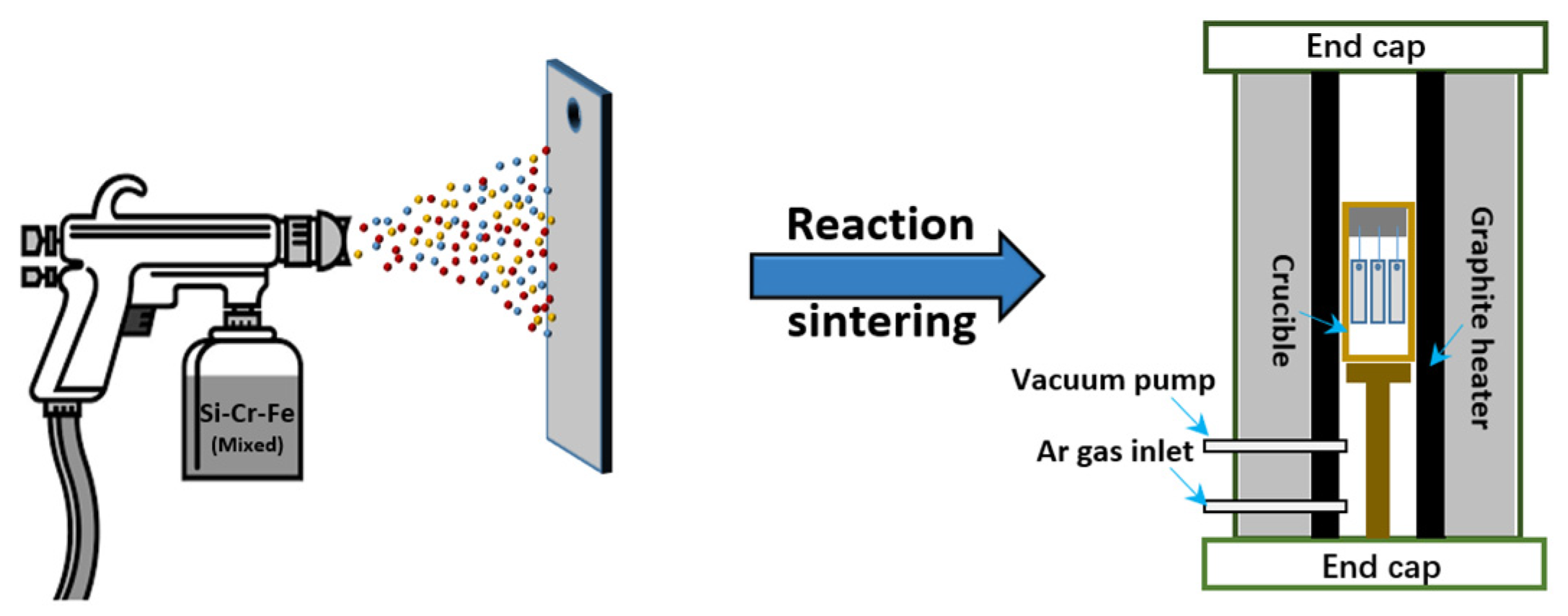
Figure 1. Flow chart of coating preparation by the slurry method.
Coatings 11 00742 g001
Figure 2. Scanning electron microscope (SEM) images of silicide coatings prepared by SS: (a,d) of pure NbSi2 coating; (b,e) NbSi2-(Fe, Cr)3Si2 composite coating; (c,f) NbSi2-(Mo,W)Si2 composite coating.
Coatings 11 00742 g002
Figure 3. SEM images of SS coating before and after oxidation: (a,d) Before oxidation; (b,e) After oxidation for 2 h; (c,f) Coating morphologies after oxidation failure.
Coatings 11 00742 g003
Figure 4. Schematic diagram of plasma spraying coating preparation.
Coatings 11 00742 g004
Figure 5. SEM images of coatings prepared by SPS under different procedures: (a,d) Pure Mo coating; (b,e) MoSi2-mullite coating; (c,f) WSi2-mullite-MoSi2 coating.
Coatings 11 00742 g005
Figure 6. SEM and LSCM images of SPS coatings after oxidation at 1500 °C for 43 h. (a) Secondary electron image; (b) LSCM image; (c) Backscattered electron image; (d) Cross-sectional images.
Coatings 11 00742 g006
Figure 7. Process flowchart of HAPC method.
Coatings 11 00742 g007
Figure 8. SEM of HAPC coatings: (a,d) Al-NbSi2 coating; (b,c) Ge/Ge-Y modified coating; (e,f) Effect of different binders BaF2/CrCl3 on coating quality.
Coatings 11 00742 g008
Figure 9. SEM of HAPC coatings after oxidation. (a,c) Surface and cross-sectional morphology of Nb-Si-Ti coating after oxidation at 1050 °C for 5 h; (b,d) (Nb, X)Si2 coating surface and cross-section morphology after oxidation at 1250 °C for 50 h.
Coatings 11 00742 g009
Figure 10. Typical SEM of two-step method coatings. (a,b) Mo-Si-B coating prepared by SPS (spray distance:100 mm, spray rate: 20 g/min) + HAPC (1000 °C/50 h) process; (c,d) Mo-Si-B coating prepared by PVD (300 °C/2 h) + HAPC (1450 °C/12 h) process.
Coatings 11 00742 g010
Figure 11. SEM of oxidized coatings prepared by the two-step method, (a,b) Mo-Si-B coating after oxidation at 1250 °C for 100 h; (c,d) Mo-Si-B coating after oxidation at 1300 °C for 24 h.
Coatings 11 00742 g011
Figure 12. Oxidation and failure mechanism of silicide coatings on Nb-based alloys, (a) Before coating oxidation; (b)Primary oxidation of coating; (c) Deep oxidation of coating.
Coatings 11 00742 g012
Figure 13. Overview of preparation parameters and oxidation resistance of Nb-based alloys surface coatings.
Coatings 11 00742 g013
Table 1. Summary for preparation and oxidation resistance of SS coatings on Nb-based alloys.
SubstrateSlurry Composition
(wt.%)
Process ConditionsCoating Composition and Thickness (μm)Oxidation SystemOxidation ProductsQuality Change
(mg/cm2)
References
Outer LayerInterface LayerOxidation Temperature
(°C)
Oxidation Time
(h)
C-10360Si-15Fe-20Cr-5NaF1400 °C/2 h
vacuum
NbSi2
Cr3Si
Fe3Si2
(200)
Nb5Si3
(30)
13002.5Nb2O5
SiO2
Fe2O3
1.5[17]
R512E20Si-35Fe-35Cr-10NaF1250 °C/4 h
vacuum
MoSi2
M5Si3
(135)
Nb5Si3
(15)
12002Nb2O5
Cr2O3
SiO2
CrNbO4
1.8[18]
Nb52145Mo-45Si-10NaF1500 °C/1 h
Ar
NbSi2
MoSi2
(110)
Nb5Si3
(25)
170025SiO2
MoSi2
−9.5[19]
Nb-Si60Si-15Fe-20Cr-5NaF1400 °C/2 h
vacuum
NbSi2
Nb4Si5CrFe3
Fe4Nb4Si7
(250)
Nb5Si3
(50)
14006.5Nb2O5
SiO2
3.5[20]
Nb-Si-Ti20Fe-20Cr-50Si-10NaF1400 °C/2 h
vacuum
NbSi2
(Fe, Cr)3Si2
(170)
Nb5Si3
(20)
14007Nb2O5
SiO2
1.9[21]
Table 3. Summary for preparation and oxidation resistance of HAPC coatings on Nb-based alloys.
SubstrateExperimental ConditionsEmbedding Components (wt.%)Coating Composition
and Thickness (μm)
Oxidation SystemOxidation ProductsQuality Change
(mg/cm2)
References
Outer LayerInterface Layer
C-1031100 °C/6 h
Ar
25Si-5NaF-70Al2O3NbSi2
Nb5Si3
(60)
Nb5Si3
(5)
1100 °C/17 hNb2O5
SiO2
3[52]
Nb-Cr1150 °C/5 h
Ar
10Si-10Al-5NaF-
75Al2O3
Al2O3
Cr3Si
Nb5Si3
(35)
Nb5Si3
Cr3Si
(5)
1200 °C/100 hSiO2
Al2O3
3.38[53]
1250 °C/8 h
Ar
10Si- 2Y2O3-5NaF-
83Al2O3
(Nb, Cr)Si2
(Cr, Nb)Si2
(185)
(Nb, Cr)5Si3
(15)
1250 °C/50 hSiO2
Cr2O3
CrNbO4
13.1[54]
Nb-Si1150 °C/10 h
Ar
10Si-10Al-5NaF-
2Y2O3-73Al2O3
(Nb, X)Si2
(Nb, X)5Si3
(40)
(Nb,Ti)3(Al, X)
(5)
1250 °C/50 hTiO2
Al2O3
SiO2
12.5[55]
1300 °C/10 h
Ar
16Si-8Ge-Y2O3-
5NaF-70Al2O3
(Nb, X)(Si, Ge)2
(180)
(Ti, Nb)5(Si, Ge)4
(Nb, X)5(Si, Ge)3
(12)
1250 °C/100 hSiO2
GeO2
TiO2
Cr2O3
2.78[56]
Nb-Ti-Al850 °C/25 h
vacuum
60Al2O3-40AlNbAl3
(160)
1000 °C/650 hNbAl3
(α-Al2O3)
1.5[57]
1050 °C/25 h
vacuum
60Al2O3-40SiNbSi2
(50)
1000 °C/650 hSiO2
TiO2
0.4
Table 4. Two-step coating preparation procedure and oxidation resistance details on Nb alloy surface.
SubstrateProcess ConditionsCoating SystemCoating Composition and Thickness (μm)Oxidation SystemOxidation ProductsQuality Change
(mg/cm2)
References
Outer LayerInterface LayerOxidation Temperature (°C)Oxidation Time
(h)
NbSPS
SD: 100 mm
SR: 20 g/min
HAPC
Ar
1000 °C/50 h
Mo-Si–BMoSi2
NbB2
NbSi2
(70)
Nb5Si3
NbB2
(10)
130024Nb2O5
SiO2
0.44[76]
C-103HAPC
1100 °C/6 h
HAPC
1050 °C/4 h
Si-BNbSi2
NbB2
(125)
NbB2
(13)
1300100Nb2O5
NbO2
B2O3
1.44[77]
Nb-SiSS
1550 °C/2 h
HAPC
Ar
1200 °C/5 h
Mo-Si-CeNbSi2
MoSi2
(80)
Nb5Si3
(4)
160024.7SiO23.57[78]
Nb-Si-TiPVD
300 °C/2 h
HAPC
Ar
1450 °C/12 h
Mo-Si–BMoSi2
(Nb,Ti)5SiB2
(50)
(Nb,Ti)Si2
(Nb, X)5Si3
(5)
130024MoO3
SiO2
−0.55[79]
Nb-Si-TiSPS
SD: 60 mm
SR: 90 g/min
HAPC
Ar
1250 °C/4 h
Si-Y-Zr(Nb,Ti)5Si4
(110)
(Nb, X)5Si3
(5)
1250100Nb2O5
TiO2
SiO2
1.6[80]
Nb-Si-TiSPS
SD: 90 mm
SR: 20 g/min
HAPC
1000 °C/40 h
Mo-Si-BMoSi2
MoB
(115)
Mo
(45)
1250100B2O3
SiO2
0.92[81]
Publisher’s Note: MDPI stays neutral with regard to jurisdictional claims in published maps and institutional affiliations.