Article

Preparation and Degradation Characteristics of MAO/APS Composite Bio-Coating in Simulated Body Fluid

School of Materials Science and Engineering, Jiangsu University of Science and Technology, Zhenjiang 212003, China
*
Authors to whom correspondence should be addressed.
Coatings 2021, 11(6), 667; https://doi.org/10.3390/coatings11060667
Submission received: 10 May 2021 / Revised: 24 May 2021 / Accepted: 27 May 2021 / Published: 31 May 2021
(This article belongs to the Special Issue Surface Modification Technology of Biomedical Metals)

Abstract

:
In this work, ZK60 magnesium alloy was employed as a substrate material to produce ceramic coatings, containing Ca and P, by micro-arc oxidation (MAO). Atmospheric plasma spraying (APS) was used to prepare the hydroxyapatite layer (HA) on the MAO coating to obtain a composite coating for better biological activity. The coatings were examined by various means including an X-ray diffractometer, a scanning electron microscope and an energy spectrometer. Meanwhile, an electrochemical examination, immersion test and tensile test were used to evaluate the in vitro performance of the composite coatings. The results showed that the composite coating has a better corrosion resistance. In addition, this work proposed a degradation model of the composite coating in the simulated body fluid immersion test. This model explains the degradation process of the MAO/APS coating in SBF.

1. Introduction

As a crucial research field in the study of the emerging clinical applications of orthopedics, some metal materials benefit from excellent machining performance, low cost, and compatibility with the human body, advantages which have drawn tremendous attention in the last several years [1,2,3,4,5,6]. Stainless steels and titanium alloys are usually the most commonly used biomedical metallic materials due to their satisfactory mechanical properties and comparative biocompatibility. However, there is a large gap in terms of elastic moduli between the natural bones and the materials mentioned above. Furthermore, patients usually suffer as a result of pain and financial burdens when using these metal materials because such materials are difficult to degrade in the human body and, therefore, a second operation is often required [7,8,9,10].
Compared with stainless steels, zirconium alloys and titanium alloys, magnesium alloys exhibit unique advantages including biodegradability, similar density and moduli to the bones, and reliable bone induction [11,12,13,14,15]. Owing to their comparative moduli, magnesium and its alloys are enabled to serve as bone implants and fixation materials. Unfortunately, such an extremely fast degradation rate of magnesium alloys can produce a large amount of hydrogen in the human body, leading to severe alkalosis, which significantly limits the applications of magnesium alloys as a biologically active material. Therefore, reducing the degradation rate to match the bone healing rate while considering its excellent biological activity has been considered to be the key factor for the performance of magnesium alloys [16,17,18,19,20]. Recently, preparing a coating with good biological activity and corrosion resistance by using micro-arc oxidation is one of the most common strategies to achieve surface modification for bio-implanted magnesium alloys [21].
Micro-arc oxidation (MAO) (also known as plasma electrolytic oxidation (PEO)) is a surface modification technology developed based on anodic oxidation. MAO uses instant high-temperature sintering in the micro-arc discharging zone to generate a coating with high hardness, high strength, insulation, wear resistance, corrosion resistance, high-temperature resistance, and other excellent properties in the valve metals [22,23,24]. The coating fabricated by this technology can be firmly attached to the magnesium alloy substrate with good compactness and excellent corrosion resistance. Besides, the whole MAO process is stable and reliable, with good repeatability and environmental friendliness. Compared with other surface modification technologies, the MAO coating shows high porosity and favorable corrosion resistance, which are considered by many researchers to be important characteristics in terms of achieving high-performance coatings [25,26,27,28,29]. During the MAO process, the surface of the metal substrate undergoes a breakdown discharge process under the instantaneous high voltage input, which results in the formation of countless discharge channels. Furthermore, phenomena such as melting, solidification and accumulation would take place in the channels that formed on the surface of the MAO coating. It should be noted that the coating is porous; hence, these pores can serve as the channels that lead to the ingression of the corrosive medium. To overcome this drawback, the researchers fabricated an additional coating with high-performance and bio-active substances on the surfaces of the MAO coatings via post-treatment, which could improve the corrosion resistance and enhance the biological activity of the magnesium implants. New research suggests that bioceramics hydroxyapatite (HA), with a Ca/P atomic ratio of 1.67, is a major inorganic component of bone tissue (such as human and animal bones and teeth). HA is not only non-toxic but also has good biocompatibility and osteoinductivity [30,31,32,33,34], and has gradually become an indispensable biological medium in the fabrication of the composite coatings on the surface of magnesium alloys.
However, pure HA still has shortcomings such as poor mechanical properties, high brittleness, low strength and poor fatigue resistance in the physiological environment, which limits its application in the field of clinical medicine. To overcome these shortcomings, the favorable biological activity and osteoinductive properties of the HA materials are utilized in order to directly deposit or coat them on the metal surface to form a coating that combines physical and biological properties, which has set off a wave of revolution in the area of surface modification technology [35].
Atmospheric plasma spraying (APS) is a technology that is widely used in the preparation of coatings [36,37,38,39,40]. Tremendous efforts have been made in the development of composite biological coatings involving the use of MAO and APS methods [41]. Daroonparvar et al. [42] fabricated an MAO coating on the surface of magnesium alloy, and then a nano-TiO2 coating was coated on the MAO by using atmospheric plasma spraying technology. The results show that nano-TiO2 particles can penetrate the micropores and defects produced during the MAO process after plasma spraying, effectively preventing the corrosive medium from penetrating the magnesium implants. Xizhi et al. [43] fabricated a Yb2SiO5 coating on the surface of magnesium alloy MAO coating by plasma spraying, achieving a good sealing effect on the MAO coating. In addition, the composite coating exhibits satisfactory performance, such as good compatibility and strong bonding force between the composite coating and the substrate. In addition, for biomedical implant materials, understanding the degradation behavior of the coating in the biological environment is the prerequisite for regulating the degradation rate. Gu et al. [44,45] found that a coating of corrosion product was deposited on the surface of the sample during the immersion process in the simulated body fluid. It is demonstrated that the corrosion product coating enables a reduction in the corrosion rate of the sample in the simulated fluid. Xiao et al. [46] showed that the degradation process of MAO coating is accompanied by the generation of degradation products and the deposition of the Ca–P product coating. Yao et al., Jie et al. and Wang et al. [47,48,49] analyzed the degradation behavior of the coating through the electrochemical impedance spectrum (EIS) test and proposed a chemical reaction mechanism that promotes the formation of the corrosion product coating.
In this work, a composite bio-coating was fabricated on the ZK60 magnesium surface via the combination of micro-arc oxidation and plasma spraying surface modifications, which aims to obtain favorable surface performance, good biological activity, and better corrosion resistance for the magnesium implants. First, the MAO treatment was used to fabricate a bio-coating on the ZK60 magnesium alloy. Then, the HA powder was selected to coat on the MAO coating by plasma spraying in order to obtain the HA contained MAO/APS composite bio-coating. Finally, a long-term immersion test was performed on the prepared composite bio-coating to investigate its corrosion behavior in simulated body fluid.

2. Materials and Methods

2.1. MAO/APS Composite Coating Structure Design

In this work, a micro-arc oxidation coating is first prepared on the surface of ZK60 magnesium alloy, and after that, the HA coating is prepared by plasma spraying on the surface of the MAO coating. Such a composite coating is considered to effectively combine excellent corrosion resistance and good biological activity. Thus, a biological composite coating with excellent performance is designed.

2.1.1. MAO Process

Wrought ZK60 magnesium alloy with the dimension of Φ 25 mm × 5 mm is used as the substrate material in this work. Before the MAO process, the substrates were polished using a Veiyee M-1 metallographic pre-mill machine (ZhiJin matelreader, Laizhou, China) in sequence with 600, 800, 1000, 1200 grit SiC waterproof sandpaper, and then treated by grit blasting. Finally, the roughened ZK60 substrate was placed in an ultrasonic cleaner for 10 min and dried in air for use. The chemical compositions of the substrates are shown in Table 1.
The MAO equipment utilizes the WHD-20 bipolar AC pulse device (Harbin Institute of Technology, Harbin, China). During the MAO test, the Mg alloy sample was used as the anode and the stainless-steel tank was used as the cathode. The magnesium alloy substrate was fixed with aluminum alloy by screw connection, and then the sample was completely immersed in the electrolyte in a hanging manner. During the test, the bio-electrolyte was cooled by circulating water and its temperature was kept below 30 °C. The specific parameters of the bio-electrolyte are shown in Table 2, where NaOH is used to maintain the pH of the bio-electrolyte at 13. The parameters of micro-arc oxidation are shown in Table 3.

2.1.2. Plasma Spraying Process

Before plasma spraying, the HA powder was dried at 200 °C for 3 h in a furnace. The average size of HA powder particles is 12 μm, the Ca/P ratio is about 1.67, the purity is about 99%, and the powder is spherical. The particle morphology is shown in Figure 1. The prepared micro-arc oxidation sample was placed in the fixture that was used for spraying, and the plasma jet was used to sweep the surface of sample 1 to 2 times to dry its surface, which avoids the breakdown of the coating. The detailed spraying parameters are shown in Table 4.

2.2. Microstructural Characterization

A scanning electron microscope (SEM, JSM-6480A, JEOL, Tokyo, Japan), equipped with an energy dispersive X-ray spectrometer, was used to characterize the corrosion morphology of the coating and simulated body fluid at different periods and analyze the constituent elements of the corrosion sample.
The phase constituents of the coating and the corrosion products after immersion in simulated body fluid were characterized by X-ray diffraction (XRD, Shimadzu Corporation, Tokyo, Japan) with a scanning speed of 2°/min, scanning range (2θ) of 20–90°, and an accelerating voltage of 40 kV.

2.3. Tensile Tests

The bonding strength of the coating was examined by using the CMT5205 tester (SKYAN, ShenZhen, China). The test method is based on the GB/T8642-2002 standard that was specially designed for plasma-sprayed coatings. The initial surface of the MAO/APS coatings was subjected to grit blasting. Then, the tested surface was glued to the tensile fixture, and reinforced with screws. The glued samples were placed in air for 3 h, and then placed in the furnace at 100 °C for 4 h of heat treatment. Finally, the samples were cooled to room temperature for the tensile test. The loading speed of the tensile force was set to 165 N/s.

2.4. Electrochemical Tests

The AC impedance method was used to analyze the corrosion behavior of the coating in the SBF. The electrochemical impedance test in this experiment was also carried out on the CS2310 electrochemical workstation (CorrTest, Wuhan, Hubei, China), and the measured frequency range was 100 kHz~100 mHz. The reference electrode was a saturated calomel electrode, the auxiliary electrode was a platinum electrode, the sample was a working electrode, the medium used was the SBF solution, the salt bridge was a saturated KCl solution, and the temperature was 37 °C. The equivalent circuit was fitted by using the ZSimpWin software (V3.60, eDAQ, Colorado Springs, CO, USA) to characterize the corrosion resistance of the coatings.

2.5. MAO Experiment

ZK60 magnesium alloys with and without the surface treatment were selected for a 20-day simulated body fluid immersion experiment. The ion content in the simulated body fluid (Simulated Body Fluid, SBF) used was the same as that in human blood (as shown in Table 5), and the reagents and dosages used to configure 1000 mL of SBF are shown in Table 6. When configuring, the container was placed in a constant temperature water bath at 36.5 ± 0.5 °C, the reagents were completely dissolved in the order listed in the table, and finally, the pH value of the SBF was adjusted to 7.45 with Tris and HCl. The static weight-loss method was used to measure the changes of the sample weight during the immersion test. The pH value of the SBF was measured by using the Banter-920-UK precision pH meter (Want Balance Instrument, ChangZhou, China). The immersion test was conducted with three sets of samples.
Before immersion, each sample (including substrate) was weighed to establish its original mass (M) with a balance, then each sample was soaked in a plastic container with SBF, and the container was placed in a constant temperature water bath at 37 °C. The ratio of the exposed area of the sample (cm2) to the volume of SBF (mL) was 1:10. The sequential pH value of SBF was recorded and the SBF was replaced by a new one every 24 h. Samples were taken out every five days, cleaned and dried, and their corroded masses were weighed (M1). The weight loss rate is:
R wt = ( M M 1 ) / M
where:
Rwt—weight loss rate;
M—the mass of the sample before corrosion (g);
M1—the mass of the sample after corrosion (g).

3. Results and discussion

3.1. Surface Morphology of MAO/APS Biological Composite Coating

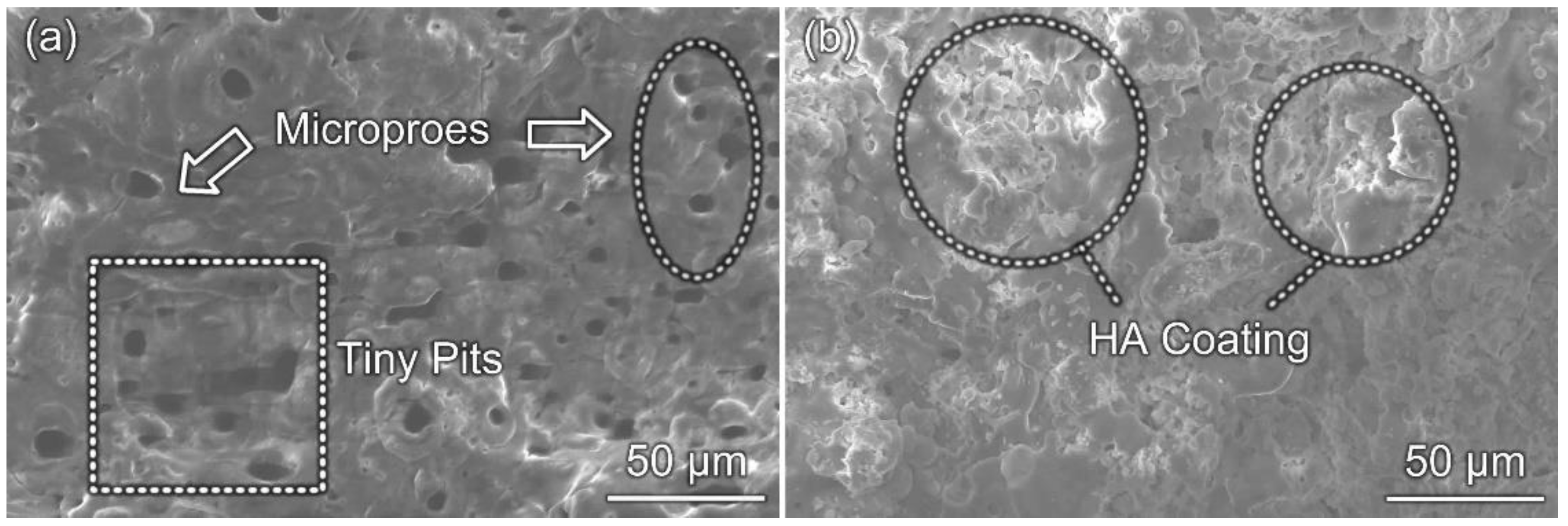
Figure 2 shows the surface morphology of MAO coating under optimized parameters and MAO/APS composite coating. Figure 2a reveals that MAO coating after sandblasting pretreatment has an uneven distribution of micropores, with small pores in some specific areas. The reason for this situation is that the surface of the substrate after the sandblasting pretreatment is extremely uneven, with considerable tiny pits. The surface condition extends the ion transmission path and causes the reaction to require more energy supply.
Figure 2b shows the surface morphology of MAO/APS composited coating under an optimized spraying process. It reveals that HA particles are heated by plasma jet to form small spherical molten droplets with a diameter of about 8–10 μm and impact the MAO coating at a high speed. At this moment, the small spherical molten droplets were stacked and spread out on the MAO coating surface, and finally, the HA coating was formed after the spraying process.
At this time, the interface between HA particles became blurred, and the melting degree of the particles increased. There were no obvious unmelted particles on the coating. The particles were flattened to a high degree and finally formed the uniform HA coating.

3.2. Analysis of Bonding Strength and Fracture of MAO/APS Composite Biological Coating

The test results show that the composite coating that exhibits good bonding strength is 20.2 MPa. Du et al. [50] showed that the bonding strength of the lower coating under the MAO process is 40–50 MPa. Since the MAO coating is produced in situ, the bonding strength of the composite coating has decreased [51].
Figure 3a shows the morphology of the cross-section of the composite coating. It reveals that the thickness of the MAO coating is 36.14 μm, and the thickness of the HA spray coating is 59.59 μm. There is no obvious interface between the two coatings, which means the coating is well combined. The MAO coatings have no obvious cracks and micropores, all of which are blind holes. This greatly improves the corrosion resistance of MAO coatings [52]. Figure 3b shows the macroscopic fracture of stretched sample and reveals that the fracture position of the composite coating is mainly at the junction of the HA coating and the MAO coating. There is still a small amount of HA remaining on the MAO coating, which is scattered on the MAO coating. Figure 4a shows the microscopic morphology of the coating fracture, which is enlarged, as shown in Figure 4b. As seen from Figure 4b, it can be found that the fracture is smooth and the remaining powder is uniform. The fracture of the composite coating is a mainly brittle fracture, with almost no plastic deformation area.
In short, the bonding method between the HA coating and the MAO substrate is mainly mechanical bonding. However, there is also a metallurgical bond in the local gap area of the MAO coating, which shows that it is not easy for the HA coating to completely fall off from the MAO substrate [53].

3.3. Phase Analysis

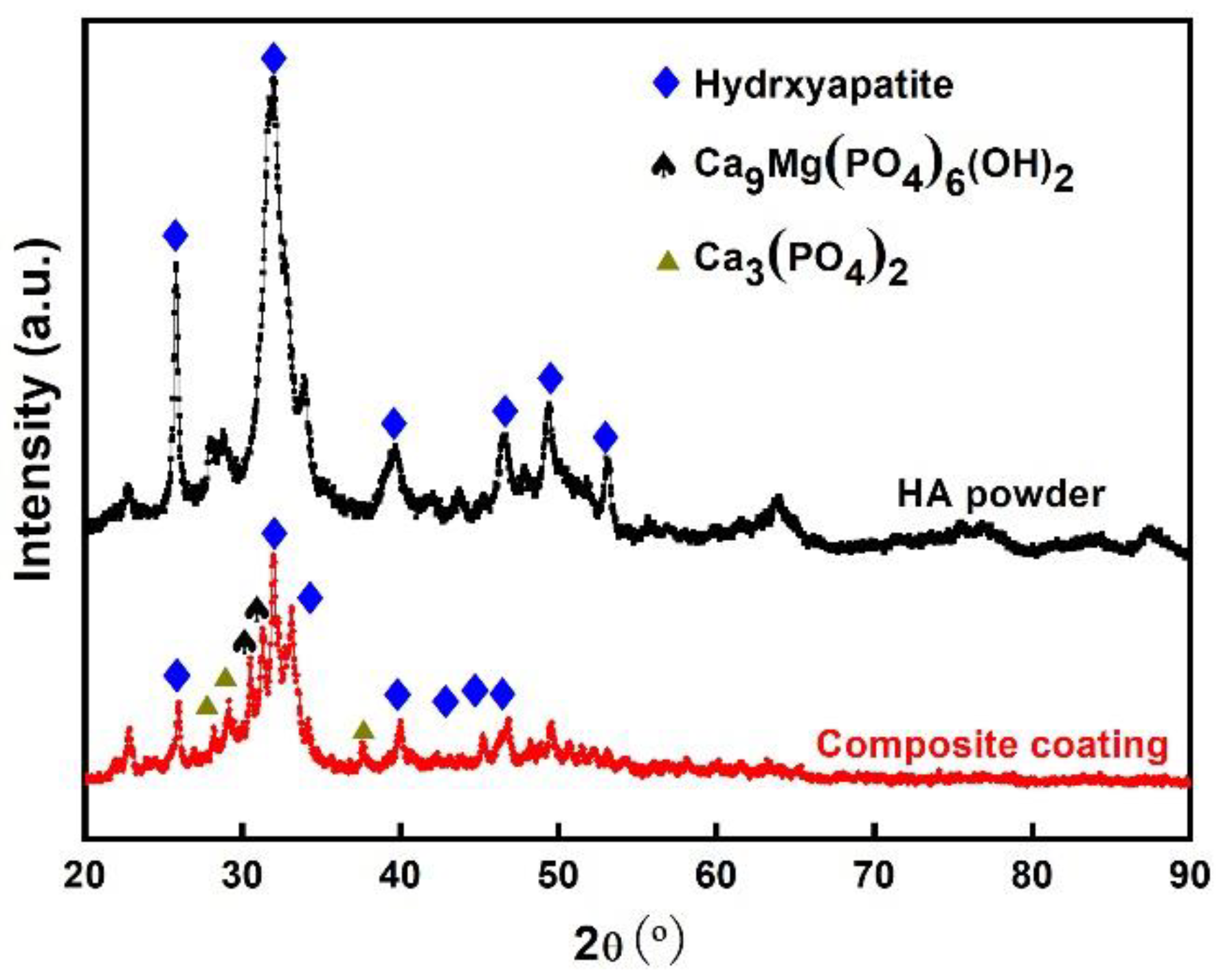
Figure 5 shows the XRD pattern of the MAO/APS biological composite coating. The XRD pattern shows that compared with the original HA powder diffraction peaks, the intensity of the HA coating diffraction peaks is weaker, indicating that the HA after spraying has a reduced crystallinity and the decomposition phase Ca3(PO4)2 is produced in the coating. During the spraying, hydroxyapatite will undergo different degrees of dehydroxylation reaction to produce OHA (Oxyhdroxyapatite, Ca10(PO4)6(OH)0.5O0.75), which contains a small number of hydroxyl groups and OA (Oxyappatite, Ca10(PO4)6O), while OHA and OA can be transformed to HA when heated in a water vapor environment. In addition, the amorphous calcium phosphate (ACP) in the coating is mainly caused by OHA during the quenching process. When the temperature is higher than 1050 °C, hydroxyapatite mainly undergoes the following decomposition reactions [54]:
Ca10(PO4)6(OH)2→CaO + Ca3(PO4)2 + H2O
The generation of ACP in the decomposition products has been reported and different opinions have been raised. Gross et al. [55] believed that the generation of ACP in the thermal spraying process is caused by HA powder. The dehydroxylated OHA in the coating is produced during the rapid cooling process. This statement mainly implies that three main factors are affecting the production of ACP: one is the degree of dehydroxylation of the HA particles during spraying; the other is the impact of the particles on the surface of the substrate; the third is the temperature of the substrate surface. Weng et al. [56] believe that the composition of the amorphous phase is mainly OA, and it is claimed that due to the high temperature during the spraying process, the hydroxyl group of HA particles is gradually lost, and finally, OA forms.
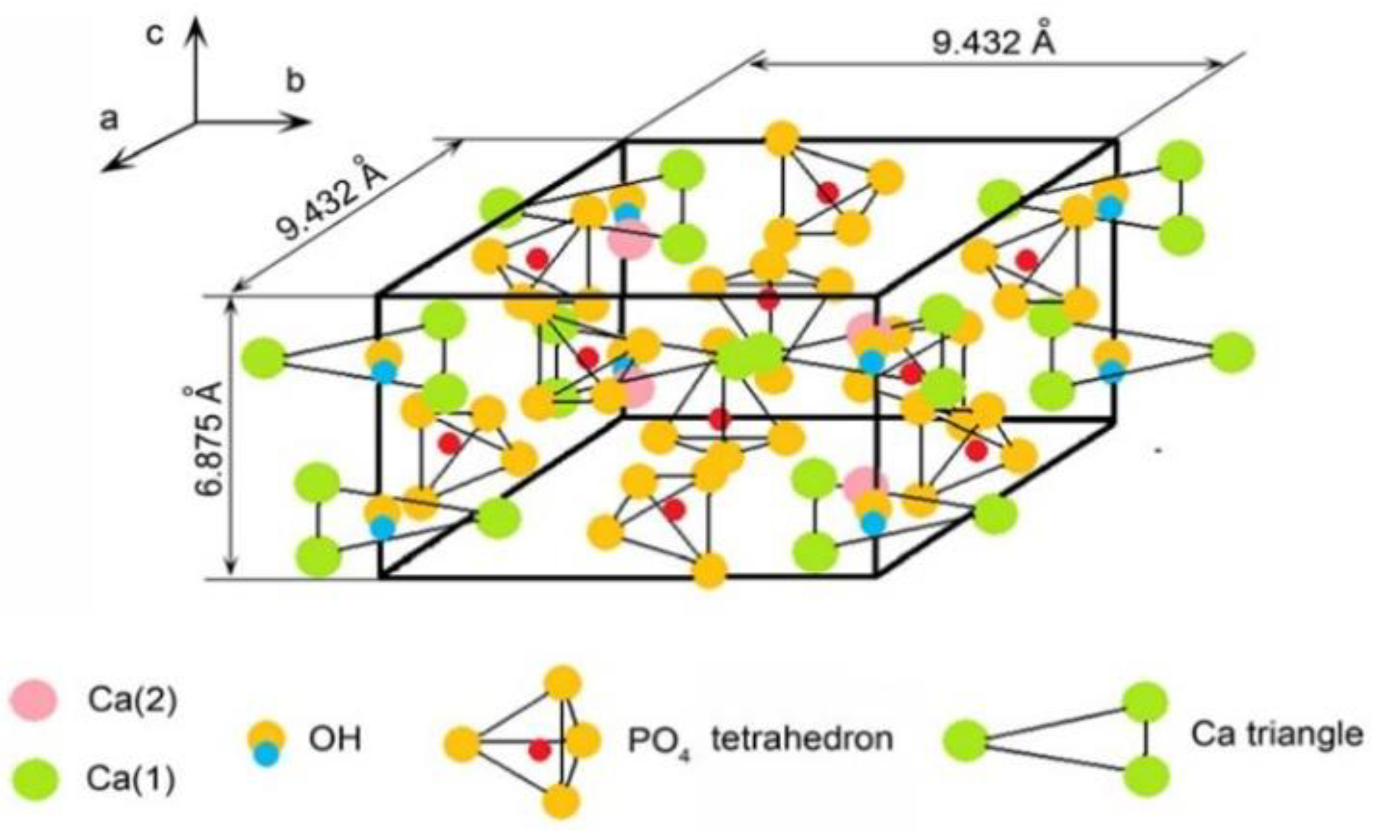
Ca9Mg(PO4)6(OH)2, namely, MgHA, is presented in the composite coating, and its formation process may be related to the crystal structure of HA itself. The HA crystal structure belongs to the hexagonal crystal system, and its lattice constants are a = b = 0.9432 nm, c = 0.9875 nm [57], as shown in Figure 6. The main component of the MAO coating is MgO, and magnesium oxide is an ionic compound. During the plasma spraying process, the instantaneous temperature is high. When the plasma jet contacts the MAO coating, free Mg2+ is easily generated, which easily enters the HA crystal. The Ca2+ vacancy formed at high temperature forms MgHA. Some cytotoxicity experiments have proved that MgHA has better biocompatibility, and animal experiments have also proved that compared with pure HA, MgHA has better osteoconductivity and bone resorption [58].

3.4. Degradation Behavior of MAO/APS Composite Coating in Simulated Body Fluid

3.4.1. pH Changes of Simulated Body Fluids and Weight Loss of Samples

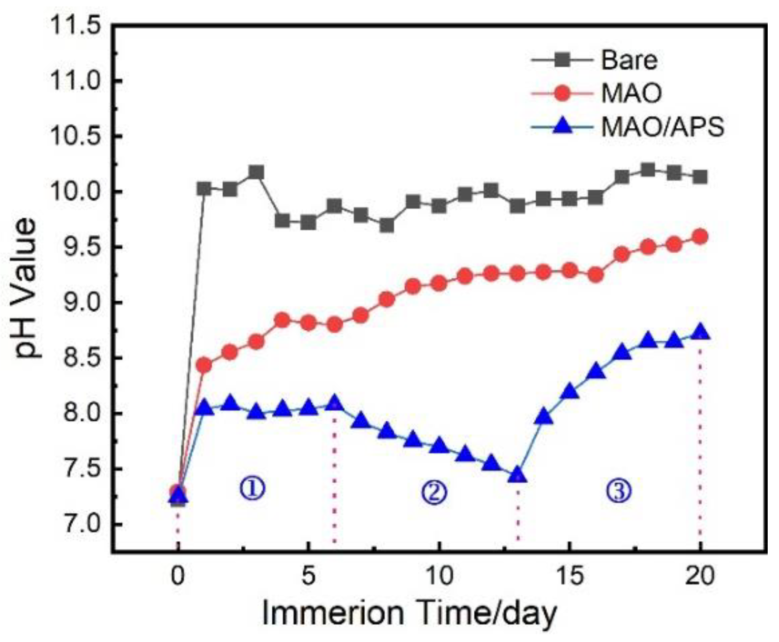
The degradation rate of magnesium alloy in the human body is too fast, which will cause the generation of hydrogen. The reaction Equations are shown in (2) and (3). The hydrogen evolution reaction will lead to an increase in the pH value around the bone tissue, which will seriously affect the living environment of bone cells [59]. Therefore, detecting the pH change of the simulated body fluid during the immersion process can reflect the hydrogen evolution rate of the magnesium alloy. Figure 7 shows the pH of SBF as a function of immersion time. It can be seen from the figure that the pH values of the SBF immersed with the bare sample and the MAO sample are always higher than those of the MAO/APS sample during immersion for 20 days.
Mg(s)→Mg2+ + 2e
2H2O(l) + 2e→2OH + H2(g)
Mg2+ + 2OH→Mg(OH)2(s)
The early stage of immersion is 0–6 days, which is tagged with 1 in Figure 7; middle-term of immersion is 7–13 days, which is tagged with 2 in Figure 7; late-term immersion is 14–20 days, which is tagged with 3 in Figure 7.
In the early stage of immersion, the pH value of the SBF immersed with the bare sample increases rapidly from 7.2 to 10.0, and the pH value is about 9.6 on the fourth day. From this point onwards, the pH value is stable. This shows that bare magnesium alloys are easily corroded in the SBF, and the main reactions that take place during this period are shown in Equations (2)–(4) [60].
Compared with the bare sample, the pH value of the SBF during the coating immersion process after the MAO treatment is slighter. Due to the low corrosion reaction rate of the MAO sample, the pH value of the SBF at the initial stage of immersion slowly increases [60].
For the composite coatings, the pH value during the immersion process is always at a relatively low level, and the change over time shows a “V” shape. The change process consists of three parts. As shown in the figure, the pH value of the SBF solution in the first stage is at a stable stage; it is basically unchanged. The second stage has a certain decrease. After 15 days, it enters the third stage, and the pH value of SBF begins to rise gradually. At the initial stage of immersion, the composite coating may only dissolve part of the amorphous phase in the simulated body fluid. Since the amorphous structure in the local area of the composite coating cannot be fully crystallized, it will dissolve faster during the immersion process [17,61,62]. Therefore, in the initial immersion process, the coating mainly locally dissolves, and the pH value of SBF is almost unchanged. The dissolution of the amorphous structure produces the Ca2+ and PO43− in the SBF solution. As time goes by, calcium and phosphorus compounds may be deposited on the local area of the composite coating. During the experiment, it is found that the surface of the coating is white. The production of corrosion products consumes OH– in the SBF during this process; hence, the pH value of the SBF drops. With the prolongation of the immersion time (the third stage), the surface of the composite coating has undergone local dissolution and deposition, and the coating becomes loose. At this moment, the corrosive medium in the SBF enters the coating, causing a corrosion reaction; hence, the pH value of the system begins to gradually rise.
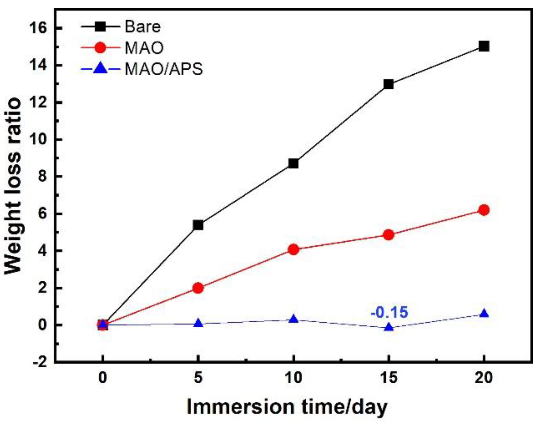
Figure 8 shows the weight loss of the sample during immersion in simulated body fluid. It can be seen from Figure 8 that the weight loss rates of bare samples, MAO samples and MAO/APS samples decrease in the SBF. For bare samples and MAO samples, as the immersion time increases, the substrate or coating is gradually corroded and degraded; hence, the weight loss rates of the samples gradually increase. As for the MAO/APS sample, there is the dissolution of the amorphous phase and the deposition of corrosion products during the immersion. Therefore, the weight loss rate of the MAO/APS sample gradually increases in the initial stage.
When the immersion was carried out for 15 days, the weight loss ratio of the sample showed a negative value for the first time. It could be indicated that the deposited amount of the corrosion products on the surface was greater than the dissolved amount of the coating. The degradation process of the composite coating in the immersion test becomes more complicated.
The surface coating of HA coating is beneficial in terms of inducing the accumulation of corrosion products containing Ca–P in the solution during the immersion process, the inner coating of MAO and the outer coating of HA, under the joint action of the coating. For this reason, the substrate is significantly protected from corrosion by corrosive media. Comparing the bare sample and the MAO sample, it can be seen that the corrosion resistance of the MAO/APS sample is greatly improved. During the 20-day simulated body fluid immersion process, the total weight loss rate is only 0.58%.

3.4.2. Changes in the Macroscopic Corrosion Morphology of the Sample

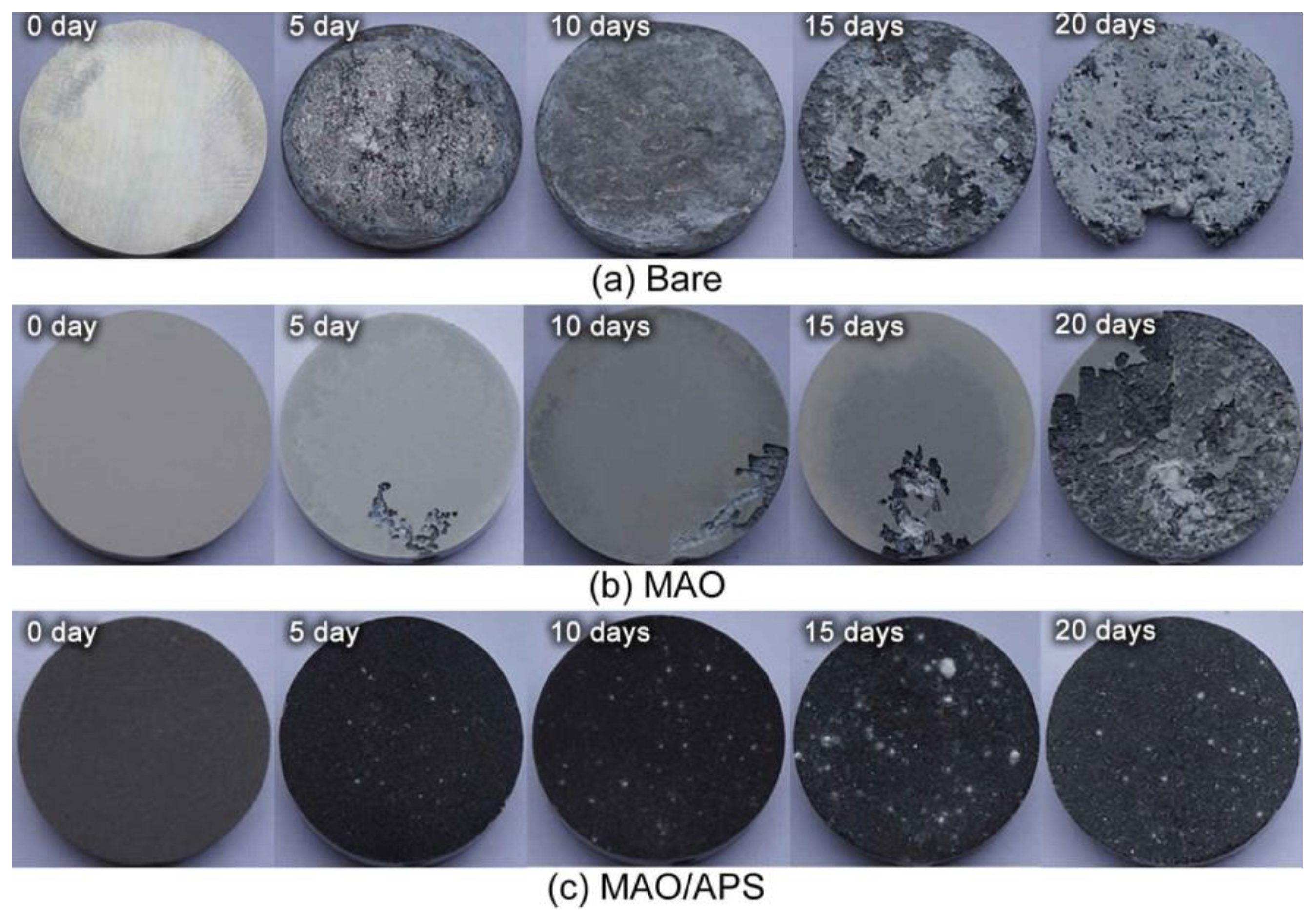
Figure 9 shows the comparison of the morphology of the bare sample, MAO sample, and MAO/APS sample after immersion in SBF solution for different numbers of days. It can be seen that during the degradation process of the bare sample in the SBF solution, uniform corrosion and local corrosion take place, and the local corrosion always takes precedence over the uniform corrosion (Figure 9a). With the extension of the immersion time, the corrosive medium gradually enters from the corrosion pit and/or from the corners to the center. On the 20th day, the corner area begins to fall off, and the surface is extremely rough.
The degradation of the MAO sample in the SBF solution is stable (Figure 9b). In the long-term immersion process, the corrosion mainly takes place at the corners of the sample and finally leads to the peeling off of the MAO coating. On the 20th day, a small amount of the MAO coating on the surface of the sample is still present.
For the MAO/APS sample, there was no obvious change during the 20-day immersion process. On the 20th day, the sample still maintained the original integrity, and no obvious corrosion degradation on the surface is found.
Figure 10 shows the surface micro-topography of MAO/APS samples with immersion time. The surface of the MAO/APS sample before immersion is rough and uneven. At the initial stage of immersion, the surface of the sample is formed by a considerable number of ellipsoidal particles. As the immersion time is prolonged, the phenomenon of the accumulation of clumps can be observed in local areas. The cracks gradually spread, which divide the surface into a large number of irregular tiny polygonal shapes. Because the HA coating on the surface of the composite coating is not completely crystallized, it contains the amorphous structure and decomposition phases produced during the spraying. The decomposition phases that follow the immersion time are speculated to be hydroxy-carbonate-apatite (HCA) [63]. These decomposition products degrade in SBF solution. The rate is much higher than the degradation rate of HA crystals [64]. Therefore, in the initial stage of immersion, the ACP and decomposition phase in the coating preferentially dissolve. Due to the production of ACP and decomposition phases, supersaturated Ca2+ and PO43+ are produced in the SBF solution, and the deposition of Ca–P compounds is prone to take place with the extension of the immersion time, as shown in Figure 10c.
In Figure 10b–d, the existence of cracks (yellow dotted line position) can be clearly observed. As the immersion time increases, the cracks gradually spread from scattered small shapes to continuous thick and deep shapes. Li et al. [65,66,67] reported that cracks are produced as a result of the volume shrinkage effect caused by the loss of moisture in the coating during the drying process. Apparently, such a statement cannot fully explain this phenomenon. The occurrence of the spreading of cracks may be related to the phenomenon of local corrosion [68]. Due to the inhomogeneity of the surface HA coating composition, the degradation rate of the local area is inconsistent; hence, corrosion is easily introduced at the interface position. As the immersion time increases, the corrosion gradually spreads, causing the cracks to expand. The coating is gradually divided into small pieces when the cracks are connected, which eventually causes the coating to fail.

3.4.3. Corrosion Products on the Surface of Coatings

Table 7 shows the changes of element content on the surface of the coating under different immersion times. It can be found that the contents of Ca and P elements increase with the immersion time, which reaches the maximum value after 15 days of immersion. The weight loss ratios of the samples can also show that the MAO/APS sample has a slight increase in weight on the 15th day, indicating that the amount of Ca–P compound deposited is greater than the local dissolution of the coating. In the later stage of immersion, Si is presented in the coating, and this element is a constituent element of the MAO coating, indicating that the composite coating, at this time, has begun to gradually fall off the HA coating.
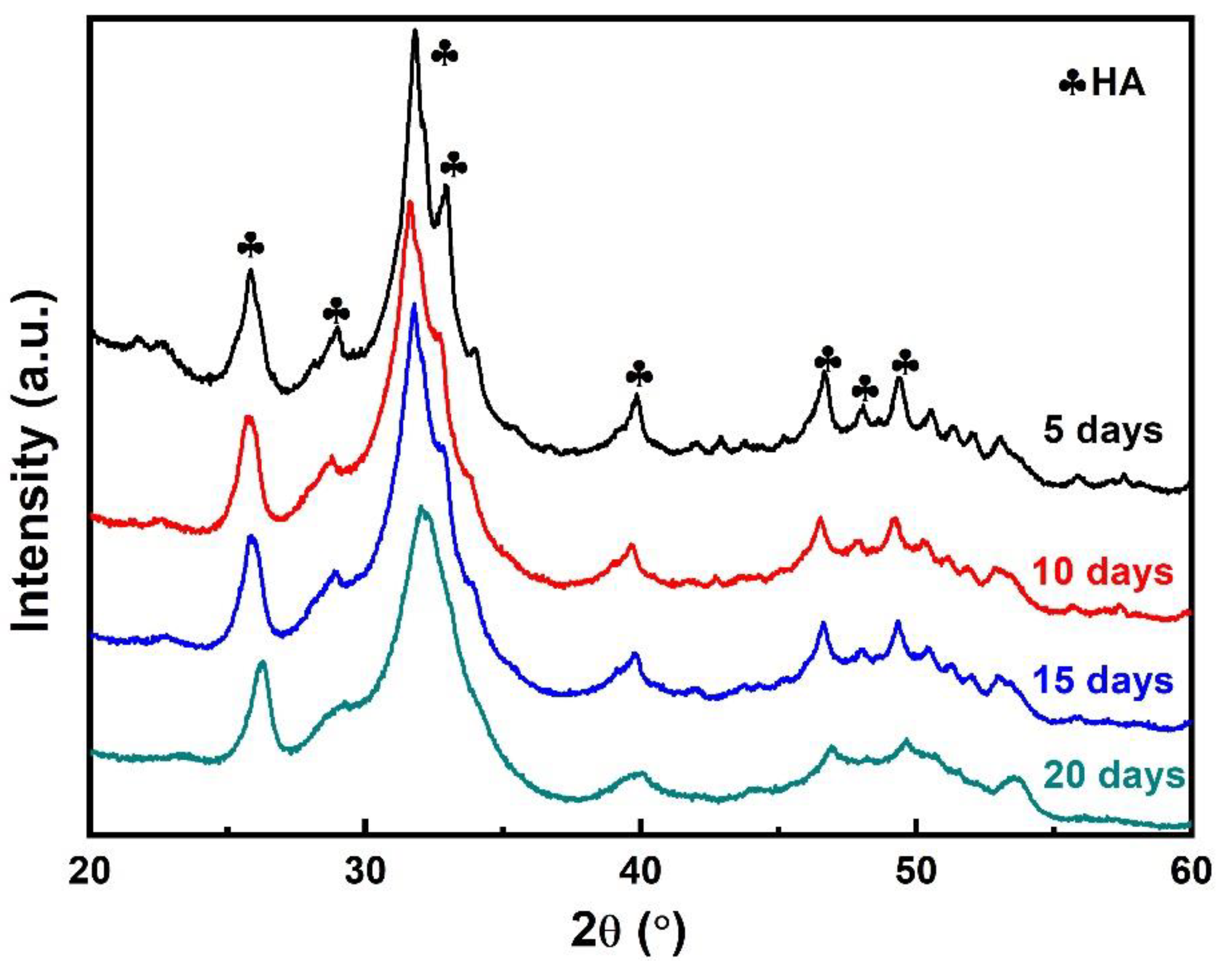
It can be seen from XRD in Figure 11 that under different immersion times, the product on the surface of the coating is mainly HA. On one hand, the initial dissolution of the amorphous phase and the decomposition phase promotes the induction of HA. In the initial stage, the surface of the implant forms certain osseointegration with bone tissue, which has good biological characteristics. On the other hand, there is no obvious compound of C in the XRD pattern; hence, it is speculated that the C element may be due to the formation of CO32− containing calcium-deficient hydroxyapatite (hydroxy-carbonate-apatite, HCA). HCA is similar to the human body’s natural bone composition, so it is also called “hydroxyapatite-like”. The main reason for its formation is that the CO32− ions in the simulated body fluid replace the hydroxyl or phosphate in the HA crystal lattice, forming the A-type, B-type or AB-type substituted hydroxyapatite carbonate [69].
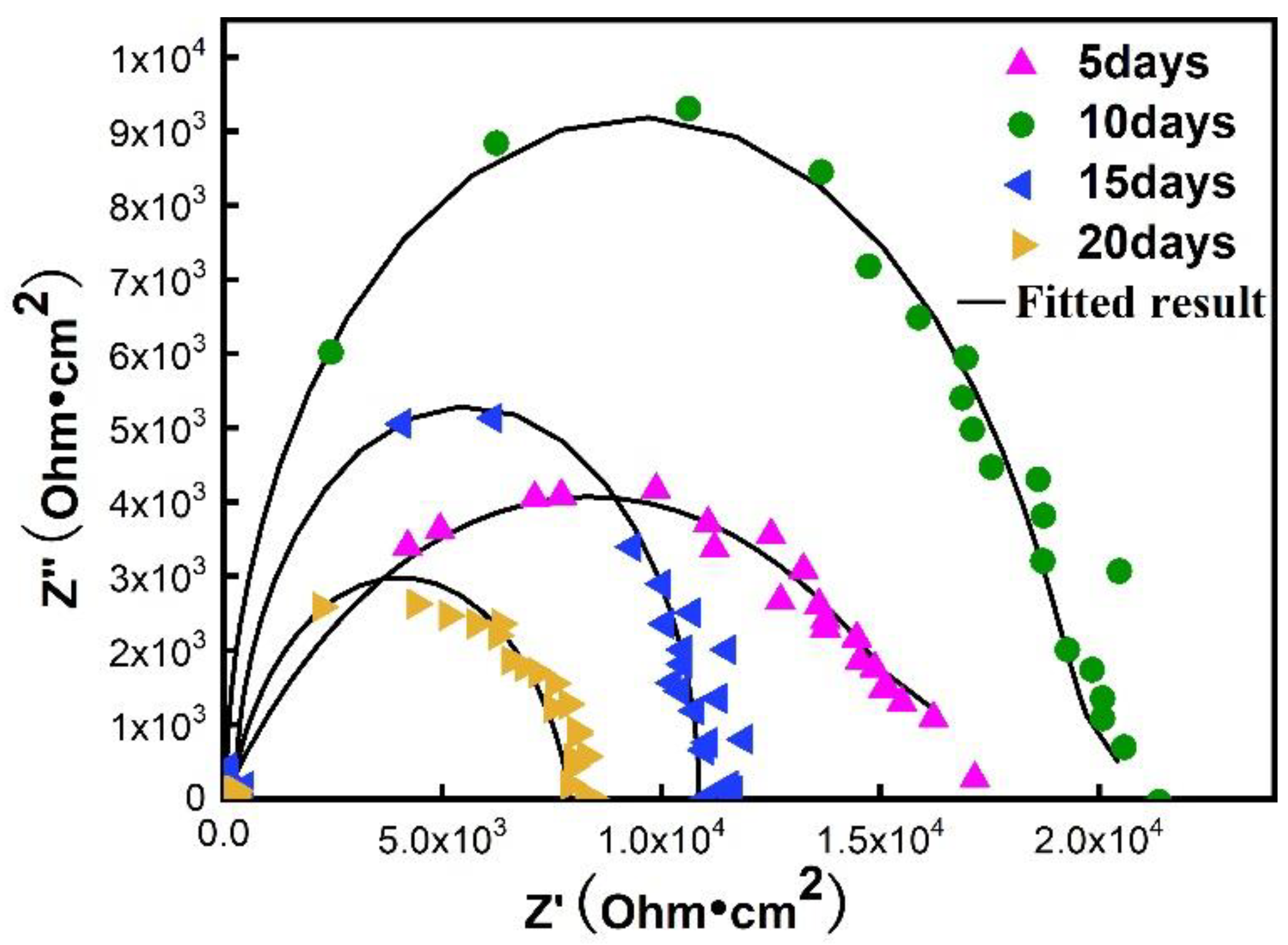
Figure 12 shows the Nyquist diagrams of the immersed samples; it can be found that the radius of the capacitive reactance loop and the impedance value at the low-frequency end of the MAO/APS, immersed for the tenth day, are at their maximum, and that the charge transfer resistance Rct, during the corrosion reaction, is the largest. At this moment, the sample shows good corrosion resistance. The reason may be that when the sample is immersed for the tenth day, the deposition of Ca–P compound on the surface is preferentially formed at the defect, which has a good inhibitory effect on the further penetration of the corrosive medium into the coating. It can also be seen from the fitted data that the resistance Rcp, representing the corrosion product, exhibits a maximum value at this time. When immersed for 20 days, the Rct was the smallest, which indicates that the deposition rate of Ca–P compound on the surface was significantly lower than the degradation rate of the coating. It can be seen from Figure 10 that the coating was dissolved after 15 days of immersion. Meanwhile, a certain amount of active Ca and P elements could be produced in the SBF solution during the degradation process. Hence, the biological activity of the composite coating presents a gradient change during the SBF solution immersion process, which is different from the immersion process of the MAO coating. To sum up, good corrosion resistance and biocompatibility can be received from the MAO/APS composite bio-coating.
According to the degradation model of AZ31 magnesium alloy in SBF, proposed by Gu et al. [70] and Khalajabadi et al. [71] to describe the degradation behavior of Mg/HA/MgO nanostructured materials prepared by powder metallurgy in SBF, combined with MAO/APS sample immersion process phenomena and analysis test results, the degradation model, and the equivalent circuit, are proposed. These are considered in accordance with the MAO/APS composite coating in SBF, which are mainly divided into the following three stages, and Table 8 lists the fitted result of EIS:
  • Early stage of immersion
During the initial immersion process of the composite membrane, a dissolution process mainly occurs. The Ca and P ions produced by the dissolution accumulate on the surface in a short time. These free Ca and P ions are easily absorbed by the damaged bone tissue to promote its growth. Therefore, part of the amorphous structure and decomposition phase existing in the HA coating is conducive, to a certain extent, to the recovery and growth of damaged bones. The equivalent circuit is shown in Figure 13a, which mainly includes three pairs of Constant Phase Element (CPE), where Rs, Rh, and Rm represent solution resistance, HA coating resistance, and MAO coating resistance, respectively.
2.
Middle period of immersion
On the one hand, due to the inconsistency of the decomposition phase (HCA), amorphous structure and crystalline HA degradation rate at the initial stage of immersion, the microcracks generated at the interface between each other expand during the middle stage of immersion, as shown in Figure 13b. On the other hand, the large amount of calcium and phosphorus ions produced by the rapid degradation of the amorphous structure and the decomposition phase produce supersaturation in the local area of the composite coating, especially at the surface defects of the composite coating. These ions react with the ions in the SBF. Ca–P compounds are formed at the coating defects and deposited on the surface. The possible reactions are represented in Equations (5) and (6). It should be noted here that HA may be crystalline hydroxyphosphorus. Greystone may also be hydroxyapatite-like, but both have good biological activity. On the other hand, as shown in Figure 13, new HA formation occurs, at this time, on the surface of the membrane, as well as the continuous expansion of cracks, and the continuous penetration of simulated body fluids into the membrane. This phenomenon is conducive to the recovery of the implant in the bone injury tissue during the formation of osseointegration. Due to the formation of the new phase of HA, the corrosion product resistance Rcp appears in the equivalent circuit.
10Ca2+ + 8OH + 6HPO42−→Ca10(PO4)6(OH)2 + 6H2O
10Ca2+ + 8OH + 2OH→Ca10(PO4)6(OH)2
3.
Late time of immersion
With the progression of the immersion test, the existence of cracks and micropores causes the surface HA coating to further fail and gradually fall off. The corrosive medium further penetrates the interior and contacts the substrate. Due to the existence of the MAO coating, the service cycle of the implant during bone healing is prolonged. During the continuous immersion process, the MAO coating will gradually degrade, participate in the normal metabolism of bone growth, and be excreted from the body.

4. Conclusions

In this work, ZK60 Mg alloy was micro-arc oxidized (MAO) before undergoing the atmospheric plasma spraying process. After the examinations of microstructures, bound strength, phase constituents, immersion tests, and electrochemical measurements, some key points can be concluded as follows:
  • The surface particles of the composite coating have a higher degree of melting and flattening, and the coating is more uniform. The thickness of the MAO coating is 36.14 μm, the thickness of the HA sprayed coating is 59.59 μm, and the average bonding strength is 20.2 MPa. Fracture analysis shows that the binding mode between the composite coatings is mechanical occlusion.
  • The pH value of the composite coating sample during the SBF immersion process showed a “V” shape with time and was at the lowest level of the three, showing the lowest degradation rate, which can effectively protect the magnesium alloy substrate.
  • The decomposition phase and amorphous structure in the HA coating on the surface of the composite coating have a faster degradation rate in the SBF solution, which effectively promotes the deposition of Ca–P compounds on the surface of the composite coating. In addition, elemental analysis and XRD tests show that the Ca–P compound is a mixture of hydroxyapatite and carbonated hydroxyapatite, which is beneficial in terms of promoting the formation of the bone bond between the implant and the damaged bone tissue at the initial stage.
  • The degradation model of the composite biological coating in SBF is proposed in accordance with this experiment, and the degradation mechanism of the composite coating in the SBF, at different stages, is explained in detail. During the initial immersion process of the composite membrane, a dissolution process mainly occurs. In the middle of immersion, due to the formation of new phase of HA, corrosion product resistance, Rcp, appears in the equivalent circuit. Furthermore, during the later stages of immersion, the MAO coating will gradually degrade, participate in the normal metabolism of bone growth, and be excreted from the body.

Author Contributions

Z.W., L.S. and S.L. conceived and designed the experiments. F.Y., Z.Z. and W.L. performed the experiments. Z.W., Q.Z. and J.P. analyzed the data. F.Y. and L.C. wrote the manuscript. All authors have read and agreed to the published version of the manuscript.

Funding

The authors would like to acknowledge the financial support provided by the Jiangsu Province six talent peaks project (Grant No. XCL-117), the Natural Science Foundation of Jiangsu (Grant No. BK20201456), the Open Foundation of Guangxi Key Laboratory of Processing for Non-ferrous Metals and Featured Materials, Guangxi University (Grant No. 2020GXYSOF01), and the Key Research and Development Program of Shaanxi (Grant No. 2020GY-251).

Institutional Review Board Statement

Not applicable.

Informed Consent Statement

Not applicable.

Data Availability Statement

The raw data supporting the conclusions of this article will be made available by the authors, without undue reservation, to any qualified researcher.

Acknowledgments

We would like to acknowledge the Instrumental Analysis Center of Jiangsu University of Science and Technology for providing technological support.

Conflicts of Interest

The authors declare no conflict of interest.

References

  1. Zhang, Z.Q.; Wang, L.; Zeng, M.Q.; Zeng, R.; Mathan, B.K.; Lin, C.G. Biodegradation behavior of micro-arc oxidation coating on magnesium alloy-from a protein perspective. Bioact. Mater. 2020, 5, 398–409. [Google Scholar] [CrossRef]
  2. Zhang, L.C.; Chen, L.Y.; Wang, L. Surface modification of titanium and titanium alloys: Technologies, developments, and future interests. Adv. Eng. Mater. 2020, 22, 1901258. [Google Scholar] [CrossRef]
  3. Zhang, L.C.; Chen, L.Y. A review on biomedical titanium alloys: Recent progress and prospect. Adv. Eng. Mater. 2019, 21, 1801215. [Google Scholar] [CrossRef] [Green Version]
  4. Zhang, L.C.; Attar, H.; Calin, M.; Eckert, J. Review on manufacture by selective laser melting and properties of titanium based materials for biomedical applications. Mater. Technol. 2016, 31, 66–76. [Google Scholar] [CrossRef]
  5. Dai, N.; Zhang, J.; Chen, Y.; Zhang, L.C. Heat treatment degrading the corrosion resistance of selective laser melted Ti-6Al-4V alloy. J. Electrochem. Soc. 2017, 164, C428. [Google Scholar] [CrossRef]
  6. Chen, L.Y.; Cui, Y.W.; Zhang, L.C. Recent development in beta titanium alloys for biomedical applications. Metals 2020, 10, 1139. [Google Scholar] [CrossRef]
  7. Hornberger, H.; Virtanen, S.; Boccaccini, A.R. Biomedical coatings on magnesium alloys—A review. Acta Biomater. 2012, 8, 2442–2455. [Google Scholar] [CrossRef]
  8. Tsn, S.N.; Park, I.S.; Lee, M.H. Strategies to improve the corrosion resistance of microarc oxidation (MAO) coated magnesium alloys for degradable implants: Prospects and challenges. Prog. Mater. Sci. 2014, 60, 1–71. [Google Scholar] [CrossRef]
  9. Chen, J.; Lin, W.; Liang, S.; Zou, L.; Wang, C.; Wang, B.; Yan, M.; Cui, X. Effect of alloy cations on corrosion resistance of LDH/MAO coating on magnesium alloy. Appl. Surf. Sci. 2019, 463, 535–544. [Google Scholar] [CrossRef]
  10. Liu, S.; Han, S.; Zhang, L.; Chen, L.Y.; Wang, L.; Zhang, L.; Tang, Y.; Liu, J.; Tang, H.; Zhang, L.C. Strengthening mechanism and micropillar analysis of high-strength NiTi–Nb eutectic-type alloy prepared by laser powder bed fusion. Compos. Part. B Eng. 2020, 200, 108358. [Google Scholar] [CrossRef]
  11. Liu, Y.; Zheng, Y.; Chen, X.H.; Yang, J.A.; Pan, H.; Chen, D.; Wang, L.; Zhang, J.; Zhu, D.; Wu, S.; et al. Fundamental theory of biodegradable metals—definition, criteria, and design. Adv. Funct. Mater. 2019, 29, 1805402. [Google Scholar] [CrossRef]
  12. Rabadia, C.D.; Liu, Y.J.; Zhao, C.H.; Wang, J.C.; Jawed, S.F.; Wang, L.Q.; Chen, L.Y.; Sun, H.; Zhang, L.C. Improved trade-off between strength and plasticity in titanium based metastable beta type Ti-Zr-Fe-Sn alloys. Mater. Sci. Eng. A 2019, 766, 138340. [Google Scholar] [CrossRef]
  13. Zhang, L.; Chen, L.Y.; Zhao, C.; Liu, Y.; Zhang, L.C. Calculation of oxygen diffusion coefficients in oxide films formed on low-temperature annealed Zr alloys and their related corrosion behavior. Metals 2019, 9, 850. [Google Scholar] [CrossRef] [Green Version]
  14. Chen, L.Y.; Shen, P.; Zhang, L.; Lu, S.; Chai, L.; Yang, Z.; Zhang, L.C. Corrosion behavior of non-equilibrium Zr-Sn-Nb-Fe-Cu-O alloys in high-temperature 0.01 M LiOH aqueous solution and degradation of the surface oxide films. Corros. Sci. 2018, 136, 221–230. [Google Scholar] [CrossRef]
  15. Pan, H.; Kang, R.; Li, J.; Xie, H.; Zeng, Z.; Huang, Q.; Yang, C.; Ren, Y.; Qin, G. Mechanistic investigation of a low-alloy Mg–Ca-based extrusion alloy with high strength–ductility synergy. Acta Mater. 2020, 186, 278–290. [Google Scholar] [CrossRef]
  16. Mao, L.; Shen, L.; Niu, J.; Zhang, J.; Ding, W.; Wu, Y.; Fan, R.; Yuan, G. Nanophasic biodegradation enhances the durability and biocompatibility of magnesium alloys for the next-generation vascular stents. Nanoscale 2013, 5, 9517–9522. [Google Scholar] [CrossRef]
  17. Rúa, J.M.; Zuleta, A.A.; Ramírez, J.; Fernández-Morales, P. Micro-arc oxidation coating on porous magnesium foam and its potential biomedical applications. Surf. Coat. Technol. 2019, 360, 213–221. [Google Scholar] [CrossRef]
  18. McEntire, B.J.; Bal, B.S.; Rahaman, M.N.; Chevalier, J.; Pezzotti, G. Ceramics and ceramic coatings in orthopaedics. J. Eur. Ceram. Soc. 2015, 35, 4327–4369. [Google Scholar] [CrossRef]
  19. Liu, P.; Wang, J.M.; Yu, X.T.; Chen, X.B.; Li, S.Q.; Chen, D.C.; Guan, S.K.; Zeng, R.C.; Cui, L.Y. Corrosion resistance of bioinspired DNA-induced Ca–P coating on biodegradable magnesium alloy. J. Magnes. Alloys 2019, 7, 144–154. [Google Scholar] [CrossRef]
  20. Durdu, S.; Aktug, S.L.; Korkmaz, K.; Yalcin, E.; Aktas, S. Fabrication, characterization and in vitro properties of silver-incorporated TiO2 coatings on titanium by thermal evaporation and micro-arc oxidation. Surf. Coat. Technol. 2018, 352, 600–608. [Google Scholar] [CrossRef]
  21. Li, L.H.; Kong, Y.M.; Kim, H.W.; Kim, Y.W.; Kim, H.E.; Heo, S.J.; Koak, J.Y. Improved biological performance of Ti implants due to surface modification by micro-arc oxidation. Biomaterials 2004, 25, 2867–2875. [Google Scholar] [CrossRef]
  22. Xu, C.; Chen, L.Y.; Zheng, C.B.; Zhang, H.Y.; Zhao, C.H.; Wang, Z.X.; Lu, S.; Zhang, J.W.; Zhang, L.C. Improved wear and corrosion resistance of microarc oxidation coatings on Ti–6Al–4V alloy with ultrasonic assistance for potential biomedical applications. Adv. Eng. Mater. 2021, 23, 2001433. [Google Scholar] [CrossRef]
  23. Asgari, M.; Aliofkhazraei, M.; Darband, G.B.; Rouhaghdam, A.S. How nanoparticles and submicron particles adsorb inside coating during plasma electrolytic oxidation of magnesium? Surf. Coat. Technol. 2020, 383, 125252. [Google Scholar] [CrossRef]
  24. Li, Y.; Li, H.; Xiong, Q.; Wu, X.; Zhou, J.; Wu, J.; Wu, X.; Qin, W. Multipurpose surface functionalization on AZ31 magnesium alloys by atomic layer deposition: Tailoring the corrosion resistance and electrical performance. Nanoscale 2017, 9, 8591–8599. [Google Scholar] [CrossRef]
  25. Rokosz, K.; Hryniewicz, T.; Raaen, S.; Gaiaschi, S.; Chapon, P.; Malorny, W.; Matýsek, D.; Dudek, Ł.; Pietrzak, K. Characterization of Porous Phosphate Coatings Created on CP Titanium Grade 2 Enriched with Calcium, Magnesium, Zinc and Copper by Plasma Electrolytic Oxidation; Preprints.org: Basel, Switzerland, 2018. [Google Scholar]
  26. Muhaffel, F.; Cimenoglu, H. Development of corrosion and wear resistant micro-arc oxidation coating on a magnesium alloy. Surf. Coat. Technol. 2019, 357, 822–832. [Google Scholar] [CrossRef]
  27. Dong, Y.T.; Liu, Z.Y.; Ma, G.F. The research progress on micro-arc oxidation of aluminum alloy. IOP Conf. Ser. Mater. Sci. Eng. 2020, 729, 012055. [Google Scholar] [CrossRef] [Green Version]
  28. Dou, J.; Chen, Y.; Yu, H.; Chen, C. Research status of magnesium alloys by micro-arc oxidation: A review. Surf. Eng. 2017, 33, 731–738. [Google Scholar] [CrossRef]
  29. Zhang, L.; Zhang, J.; Chen, C.F.; Gu, Y. Advances in microarc oxidation coated AZ31 Mg alloys for biomedical applications. Corros. Sci. 2015, 91, 7–28. [Google Scholar] [CrossRef]
  30. Li, X.; Chen, M.; Wang, P.; Yao, Y.; Han, X.; Liang, J.; Jiang, Q.; Sun, Y.; Fan, Y.; Zhang, X. A highly interweaved HA-SS-nHAp/collagen hybrid fibering hydrogel enhances osteoinductivity and mineralization. Nanoscale 2020, 12, 12869–12882. [Google Scholar] [CrossRef]
  31. Habibovic, P.; Barrère, F.; Van Blitterswijk, C.A.; de Groot, K.; Layrolle, P. Biomimetic hydroxyapatite coating on metal implants. J. Am. Ceram. Soc. 2002, 85, 517–522. [Google Scholar] [CrossRef] [Green Version]
  32. Feng, C.; Zhang, K.; He, R.; Ding, G.; Xia, M.; Jin, X.; Xie, C. Additive manufacturing of hydroxyapatite bioceramic scaffolds: Dispersion, digital light processing, sintering, mechanical properties, and biocompatibility. J. Adv. Ceram. 2020, 9, 360–373. [Google Scholar] [CrossRef]
  33. Bose, S.; Tarafder, S.; Bandyopadhyay, A. 7—Hydroxyapatite coatings for metallic implants. In Hydroxyapatite (Hap) for Biomedical Applications; Woodhead Publishing: Cambridge, UK, 2015; pp. 143–157. [Google Scholar]
  34. Li, C.; Yao, X.; Zhang, X.; Huang, X.; Hang, R. Corrosion behavior and cytocompatibility of nanostructured hydroxyapatite hydrothermally grown on porous MgO coatings with different P contents on magnesium. Mater. Lett. 2020, 264, 127136. [Google Scholar] [CrossRef]
  35. Ferraz, M.; Monteiro, F.; Manuel, C. Hydroxyapatite nanoparticles: A review of preparation methodologies. J. Appl. Biomater. Biomech. 2003, 2, 74–80. [Google Scholar]
  36. Fauchais, P. Understanding plasma spraying. J. Phys. D: Appl. Phys. 2004, 37, R86–R108. [Google Scholar] [CrossRef]
  37. Chen, L.Y.; Xu, T.; Wang, H.; Sang, P.; Lu, S.; Wang, Z.X.; Chen, S.; Zhang, L.C. Phase interaction induced texture in a plasma sprayed-remelted NiCrBSi coating during solidification: An electron backscatter diffraction study. Surf. Coat. Technol. 2019, 358, 467–480. [Google Scholar] [CrossRef]
  38. Sang, P.; Zhao, C.; Wang, Z.X.; Wang, H.; Lu, S.; Song, D.; Xu, J.H.; Zhang, L. Particle size-dependent microstructure, hardness and electrochemical corrosion behavior of atmospheric plasma sprayed NiCrBSi coatings. Metals 2019, 9, 1342. [Google Scholar] [CrossRef] [Green Version]
  39. Sha, J.; Liu, Y.T.; Yao, Z.J.; Lu, S.; Wang, Z.X.; Zang, Q.H.; Mao, S.H.; Zhang, L. Phase transformation-induced improvement in hardness and high-temperature wear resistance of plasma-sprayed and remelted NiCrBSi/WC coatings. Metals 2020, 10, 1688. [Google Scholar] [CrossRef]
  40. Chen, L.Y.; Wang, H.; Zhao, C.; Lu, S.; Wang, Z.X.; Sha, J.; Chen, S.; Zhang, L.C. Automatic remelting and enhanced mechanical performance of a plasma sprayed NiCrBSi coating. Surf. Coat. Technol. 2019, 369, 31–43. [Google Scholar] [CrossRef]
  41. Fan, X.; Liu, Y.; Xu, Z.; Wang, Y.; Zou, B.; Gu, L.; Wang, C.; Chen, X.; Khan, Z.S.; Yang, D.; et al. Preparation and characterization of 8YSZ thermal barrier coatings on rare earth-magnesium alloy. J. Therm. Spray Technol. 2011, 20, 948–957. [Google Scholar] [CrossRef] [Green Version]
  42. Daroonparvar, M.; Yajid, M.A.M.; Yusof, N.M.; Bakhsheshi-Rad, H.R.; Hamzah, E.; Mardanikivi, T. Deposition of duplex MAO layer/nanostructured titanium dioxide composite coatings on Mg–1%Ca alloy using a combined technique of air plasma spraying and micro arc oxidation. J. Alloys Compd. 2015, 649, 591–605. [Google Scholar] [CrossRef]
  43. Fan, X.; Xu, J.; Wang, Y.; Ma, H.; Zhao, S.; Zhou, X.; Cao, X. Preparation and corrosion resistance of MAO layer/Yb2SiO5 composite coating on Mg alloy. Surf. Coat. Technol. 2014, 240, 118–127. [Google Scholar] [CrossRef]
  44. Gu, Y.; Chen, C.F.; Bandopadhyay, S.; Ning, C.; Zhang, Y.; Guo, Y. Corrosion mechanism and model of pulsed DC microarc oxidation treated AZ31 alloy in simulated body fluid. Appl. Surf. Sci. 2012, 258, 6116–6126. [Google Scholar] [CrossRef]
  45. Gu, Y.; Bandopadhyay, S.; Chen, C.F.; Ning, C.; Guo, Y. Long-term corrosion inhibition mechanism of microarc oxidation coated AZ31 Mg alloys for biomedical applications. Mater. Des. 2013, 46, 66–75. [Google Scholar] [CrossRef]
  46. Lin, X.; Yang, X.; Tan, L.; Li, M.; Wang, X.; Zhang, Y.; Yang, K.; Hu, Z.; Qiu, J. In vitro degradation and biocompatibility of a strontium-containing micro-arc oxidation coating on the biodegradable ZK60 magnesium alloy. Appl. Surf. Sci. 2014, 288, 718–726. [Google Scholar] [CrossRef]
  47. Pan, Y.; He, S.; Wang, D.; Huang, D.; Zheng, T.; Wang, S.; Dong, P.; Chen, C. In vitro degradation and electrochemical corrosion evaluations of microarc oxidized pure Mg, Mg-Ca and Mg-Ca-Zn alloys for biomedical applications. Mater. Sci. Eng. C 2015, 47, 85–96. [Google Scholar] [CrossRef]
  48. Zhang, J.; Dai, C.; Wei, J.; Wen, Z.; Zhang, S.; Chen, C. Degradable behavior and bioactivity of micro-arc oxidized AZ91D Mg alloy with calcium phosphate/chitosan composite coating in m-SBF. Colloids Surf. B 2013, 111, 179–187. [Google Scholar] [CrossRef]
  49. Wang, Y.M.; Guo, J.W.; Shao, Z.K.; Zhuang, J.P.; Jin, M.S.; Wu, C.J.; Wei, D.Q.; Zhou, Y. A metasilicate-based ceramic coating formed on magnesium alloy by microarc oxidation and its corrosion in simulated body fluid. Surf. Coat. Technol. 2013, 219, 8–14. [Google Scholar] [CrossRef]
  50. Du, Q.; Wei, D.; Wang, Y.; Cheng, S.; Liu, S.; Zhou, Y.; Jia, D. The effect of applied voltages on the structure, apatite-inducing ability and antibacterial ability of micro arc oxidation coating formed on titanium surface. Bioact. Mater. 2018, 3, 426–433. [Google Scholar] [CrossRef]
  51. Tang, H.; Han, Y.; Wu, T.; Tao, W.; Jian, X.; Wu, Y.; Xu, F. Synthesis and properties of hydroxyapatite-containing coating on AZ31 magnesium alloy by micro-arc oxidation. Appl. Surf. Sci. 2017, 400, 391–404. [Google Scholar] [CrossRef]
  52. Xia, Q.; Li, X.; Yao, Z.; Jiang, Z. Investigations on the thermal control properties and corrosion resistance of MAO coatings prepared on Mg-5Y-7Gd-1Nd-0.5Zr alloy. Surf. Coat. Technol. 2021, 409, 126874. [Google Scholar] [CrossRef]
  53. Wang, X.; Li, B.; Zhou, L.; Ma, J.; Zhang, X.; Li, H.; Liang, C.; Liu, S.; Wang, H. Influence of surface structures on biocompatibility of TiO2/HA coatings prepared by MAO. Mater. Chem. Phys. 2018, 215, 339–345. [Google Scholar] [CrossRef]
  54. Vilardell, A.M.; Cinca, N.; Garcia-Giralt, N.; Dosta, S.; Cano, I.G.; Nogués, X.; Guilemany, J.M. In-vitro comparison of hydroxyapatite coatings obtained by cold spray and conventional thermal spray technologies. Mater. Sci. Eng. C 2020, 107, 110306. [Google Scholar] [CrossRef]
  55. Gross, K.A.; Phillips, M.R. Identification and mapping of the amorphous phase in plasma-sprayed hydroxyapatite coatings using scanning cathodoluminescence microscopy. J. Mater. Sci. Mater. Med. 1998, 9, 797–802. [Google Scholar] [CrossRef]
  56. Weng, J.; Liu, X.; Zhang, X.; Ma, Z.; Ji, X.; Zyman, Z. Further studies on the plasma-sprayed amorphous phase in hydroxyapatite coatings and its deamorphization. Biomaterials 1993, 14, 578–582. [Google Scholar] [CrossRef]
  57. Shen, H.Z.; Guo, N.; Zhao, L.; Shen, P. Role of ion substitution and lattice water in the densification of cold-sintered hydroxyapatite. Scr. Mater. 2020, 177, 141–145. [Google Scholar] [CrossRef]
  58. Xiong, L.; Wang, P.; Hunter, M.N.; Kopittke, P.M. Bioavailability and movement of hydroxyapatite nanoparticles (HA-NPs) applied as a phosphorus fertiliser in soils. Environ. Sci. Nano 2018, 5, 2888–2898. [Google Scholar] [CrossRef]
  59. Song, J.; Jin, P.; Li, M.; Liu, J.; Wu, D.; Yao, H.; Wang, J. Antibacterial properties and biocompatibility in vivo and vitro of composite coating of pure magnesium ultrasonic micro-arc oxidation phytic acid copper loaded. J. Mater. Sci. Mater. Med. 2019, 30, 49. [Google Scholar] [CrossRef]
  60. Wang, Z.X.; Xu, L.; Zhang, J.W.; Ye, F.; Lv, W.G.; Xu, C.; Lu, S.; Yang, J. Preparation and degradation behavior of composite bio-coating on ZK60 magnesium alloy using combined micro-arc oxidation and electrophoresis deposition. Front. Mater. 2020, 7, 190. [Google Scholar] [CrossRef]
  61. Zhang, L.C.; Xu, J.; Ma, E. Consolidation and properties of ball-milled Ti50Cu18Ni22Al4Sn6 glassy alloy by equal channel angular extrusion. Mater. Sci. Eng. A 2006, 434, 280–288. [Google Scholar] [CrossRef]
  62. Zhang, L.C.; Shen, Z.Q.; Xu, J. Mechanically milling-induced amorphization in Sn-containing Ti-based multicomponent alloy systems. Mater. Sci. Eng. A 2005, 394, 204–209. [Google Scholar] [CrossRef]
  63. Landi, E.; Celotti, G.; Logroscino, G.; Tampieri, A. Carbonated hydroxyapatite as bone substitute. J. Eur. Ceram. Soc. 2003, 23, 2931–2937. [Google Scholar] [CrossRef]
  64. Zheng, Z.; Zhao, M.C.; Tan, L.; Zhao, Y.C.; Xie, B.; Huang, L.; Yin, D.; Yang, K.; Atrens, A. Biodegradation behaviour of hydroxyapatite-containing self-sealing micro-arc-oxidation coating on pure Mg. Surf. Eng. 2021, 1–11. [Google Scholar] [CrossRef]
  65. Li, Y.; Lu, F.; Li, H.; Zhu, W.; Pan, H.; Tan, G.; Lao, Y.; Ning, C.; Ni, G. Corrosion mechanism of micro-arc oxidation treated biocompatible AZ31 magnesium alloy in simulated body fluid. Prog. Nat. Sci. Mater. Int. 2014, 24, 516–522. [Google Scholar] [CrossRef] [Green Version]
  66. Liu, G.; Tang, S.; Li, D.; Hu, J. Self-adjustment of calcium phosphate coating on micro-arc oxidized magnesium and its influence on the corrosion behaviour in simulated body fluids. Corros. Sci. 2014, 79, 206–214. [Google Scholar] [CrossRef]
  67. Agarwal, S.; Curtin, J.; Duffy, B.; Jaiswal, S. Biodegradable magnesium alloys for orthopaedic applications: A review on corrosion, biocompatibility and surface modifications. Mater. Sci. Eng. C 2016, 68, 948–963. [Google Scholar] [CrossRef] [PubMed] [Green Version]
  68. Bocchetta, P.; Chen, L.Y.; Tardelli, J.D.; Reis, A.C.; Almeraya-Calderón, F.; Leo, P. Passive layers and corrosion resistance of biomedical Ti-6Al-4V and β-Ti alloys. Coatings 2021, 11, 487. [Google Scholar] [CrossRef]
  69. Srivastava, A.; Ahmed, R.; Shah, S. Carbonic acid resistance of hydroxyapatite-containing cement. SPE Drill. Complet. 2020, 35, 088–099. [Google Scholar] [CrossRef]
  70. Gu, Y.; Bandopadhyay, S.; Chen, C.F.; Guo, Y.; Ning, C. Effect of oxidation time on the corrosion behavior of micro-arc oxidation produced AZ31 magnesium alloys in simulated body fluid. J. Alloys Compd. 2012, 543, 109–117. [Google Scholar] [CrossRef]
  71. Khalajabadi, S.Z.; Abdul Kadir, M.R.; Izman, S.; Kasiri-Asgarani, M. Microstructural characterization, biocorrosion evaluation and mechanical properties of nanostructured ZnO and Si/ZnO coated Mg/HA/TiO2/MgO nanocomposites. Surf. Coat. Technol. 2015, 277, 30–43. [Google Scholar] [CrossRef]
Figure 1. The SEM images of HA powder.
Coatings 11 00667 g001
Figure 2. Morphologies of coatings: (a) surface morphology of MAO coating; (b) surface morphology MAO/APS coating.
Coatings 11 00667 g002
Figure 3. Cross-section morphology of MAO/APS coating: (a) macroscopic fracture morphology of sample; (b) macroscopic fracture morphology of MAO/APS coating.
Coatings 11 00667 g003
Figure 4. Tensile fracture morphology of the sample: (a) ×200; (b) ×500.
Coatings 11 00667 g004
Figure 5. XRD patterns of composite coating and original HA powder.
Coatings 11 00667 g005
Figure 6. Diagrammatic sketch of the crystal structure of HA.
Coatings 11 00667 g006
Figure 7. pH values of the SBF during immersion test.
Coatings 11 00667 g007
Figure 8. Weight loss rate of samples over time.
Coatings 11 00667 g008
Figure 9. Macro morphology of samples after immersion: (a) bare; (b) MAO; (c) MAO/APS.
Coatings 11 00667 g009
Figure 10. Morphology of samples after immersion: (a) 5 days; (b) 10 days; (c) 15 days; (d) 20 days.
Coatings 11 00667 g010
Figure 11. XRD patterns of MAO/APS coatings immersed for different numbers of days.
Coatings 11 00667 g011
Figure 12. Nyquist plots of immersion samples in SBF.
Coatings 11 00667 g012
Figure 13. A physical model of the degradation process of MAO/APS samples in the SBF solution with equivalent circuits for fitting the EIS data: (a) initial-term of immersion; (b) middle-term of immersion; (c) late-term immersion.
Coatings 11 00667 g013
Table 1. Compositions of the wrought ZK60 magnesium alloy (wt.%).
ElementZnZrImpuritiesMg
Content4.8–6.2>0.45≤0.30balance
Table 2. Composition of bio-electrolyte for MAO on ZK60 alloy.
Composition.Na2SiO3Ca(AC)2(NaPO3)6NaH2PO4NaOH
Concentration/(g/L)6.00.50.80.5-
Table 3. Parameters of micro-arc oxidation.
Power Control ModeCurrent Density/(A/dm2)Frequency/HzDuty Cycle/%Response Time/min
Constant current20500+40/−6015
Table 4. Plasma spraying parameters selected for depositing HA coating.
ParametersSpraying
Voltage (V)60
Current (A)500
Powder feed rate (g/s)0.3
Spray step (mm)3
Gun traverse rate (mm/s)100
Main gas Ar (dm3/s)4.1
Secondary gas N2 (dm3/s)1
Feed gas Ar (dm3/s)2.1
Distance to the substrate (mm)110
Table 5. Ion concentration of SBF and blood plasma (mol/L).
SolutionNa+K+Mg2+Ca2+ClHCO3−HPO42−SO42−
SBF142.05.01.52.5148.84.21.00.5
Blood Plasma142.05.01.52.5103.027.01.00.5
Table 6. Reagents and dose for 1000 mL SBF.
ReagentNaClNaHCO3KClK2HPO4·3H2OMgCl2·6H2O1.0M-HClNa2SO4CaCl2
Dosage (g)8.0350.3550.2250.2310.31139 mL0.0720.278
Table 7. Variation of elements contents of the coating over immersion time (at.%).
COMgCaPNa
5 days20.06 ± 1.3456.29 ± 0.610.80 ± 0.1912.90 ± 0.119.41 ± 0.040.32 ± 0.10
10 days15.36 ± 1.2959.20 ± 0.581.11 ± 0.2013.90 ± 0.129.82 ± 0.030.48 ± 0.11
15 days15.46 ± 1.3055.02 ± 0.600.80 ± 0.2417.31 ± 0.0910.28 ± 0.050.58 ± 0.12
20 days16.25 ± 1.3559.10 ± 0.620.99 ± 0.2213.01 ± 0.119.32 ± 0.030.40 ± 0.11
Table 8. EIS data of MAO/APS samples after immersion in SBF for various durations.
Immersion TimeRsRcpRhRmRct
5 days19.03-1.1670 × 10428614.934 × 105
10 days52.2030531.6200 × 10437485.030 × 105
15 days0.2342272.1271.9101.14724
20 days149.10.0759754.79472.43409
Publisher’s Note: MDPI stays neutral with regard to jurisdictional claims in published maps and institutional affiliations.