Article

Highly Flexible Wind Turbine Blades Utilizing Corrugated Surface Hinges

by
Mogeeb Elrahman Elsheikh
Production and Mechanical Design Department, Faculty of Engineering, Port Said University, Port Said 42526, Egypt
Coatings 2021, 11(6), 635; https://doi.org/10.3390/coatings11060635
Submission received: 9 April 2021 / Revised: 7 May 2021 / Accepted: 12 May 2021 / Published: 26 May 2021
(This article belongs to the Special Issue New Advances in Ceramic Coatings and Its Applications)

Abstract

:
An anthropomorphic wind turbine blade was the suggested design that had a flexure hinge at root, middle, and tip regions. The inter-distances of the flexure hinges follow the Fibonacci sequence and resembled the natural finger through binding. Therefore, the present study designs various corrugated flexure hinges. NACA0012 is chosen as the basic airfoil for designing the corrugated flexure hinges with different geometrical profiles and leading edges. The designs are based on morphing technology and the main geometrical parameters of the corrugation, the pitch distance along the span and the height, are inspired by tubercles of the whale flippers. The study uses the finite element method to define the significant strength characteristics of each design flap-wise, edge-wise, torsional stiffness, and buckling resistance in order to assign the best fit corrugation profile for each region of the blade.

1. Introduction

Folding wings, variable-span (telescoping) wings, adapting airfoil, and deployable wings are recent morphing technology to enhance the aerodynamics performance that depends on the wing shape [1]. Generating adequate thrust and lifting force to overcome the drag resistance and gravity is the main objective according to the missions and flight conditions [1]. Besides, alleviating stresses and aerodynamic braking of the gigantic wind turbine blade are other roles of the morphing technology by replacing the stiff parts with more compliant structures [2].
Morphing technologies based on smart materials and corrugated structures will be required to enable an aircraft to perform in-flight configuration changes for optimum performance [3]. The corrugated structures attain the previous aim for flexing and deforming the wing skin. They distinguish with anisotropic behavior that is stiff along the corrugations direction, but flexible in the transverse direction [4].
The morphing of wings and wind turbine blades can be classified into two main groups, in-plane morphing and out-of-plane morphing [2]. The morphing degree can be classified as large, medium, or small depending on the dimensions that vary [1]. Reference [5] presented NACA0012 airfoil with different sized corrugated profile along the cord-wise direction and tested aerodynamics performance. The corrugations reduced the lift-curve slope and lift-drag ratio. By increasing the Reynolds number, there were slightly larger lift curve slopes.
The corrugations along the span-wise direction were a solution for wing span morphing due to extremely anisotropic behavior, allowing flexibility in the spanwise/morphing direction while maintaining sufficient stiffness in other directions. Thus, the actuator deforms the wing span, reducing the span on the ground for load alleviation or increasing the span length to enhance the aerodynamics during flight [6].
The pitch distance, sheet thickness, and corrugations height are the main geometrical parameters of the corrugations that impact the morphing [1]. Therefore, optimization was used to verify the influence of corrugations height and the angle on the morphing displacement.
In nature, a number of insects including locusts, dragonflies, and damselflies use corrugated wings that do not appear to be very suitable for flight [4]. But, researchers found that negative pressure would be produced at the valleys of the corrugated dragonfly wing model, which would contribute to the increased lift [7]. The corrugated dragonfly airfoil had much better performance over the streamlined airfoil and the flat plate at low Reynolds number level [8]. Along the transverse direction of the wavy corrugations enables the insect wing to sustain the aerodynamics and inertial loads [1]. The humpback whale’s flippers have certain projections called tubercles which help it to delay flow separation while performing tight underwater maneuvers and their leading edges follow sinusoidal patterns [9].
The anthropomorphic wind turbine blade motivates the author to present various designs of flexure hinges. Each region of this blade had a flexure hinge, at the tip, mid-span, and root enabling the blade to fold as the natural finger during transportation. When the wind turbine blade reaches to site, the flexure hinges are reinforced with the wires [10].
The method section of the study describes the full detail design of the introduced flexure hinges. The sinusoidal, circular and rectangular profiles of the corrugations are selected and swept along NACA0012 to form the flexure hinges. The main geometrical parameters of the corrugations are inspired from tubercles of whales.
The finite element method modeling section investigates the mechanical strength of the flexure hinge designs. The Flap-wise, edge-wise, torsional stiffness and the buckling resistance are estimated. The study fabricates scaled samples by rapid prototyping. Accordingly, the following sections assign the best fit corrugation profile for each region of the wind turbine blade to sustain the operating conditions.

2. Description of the Flexure Hinge Designs

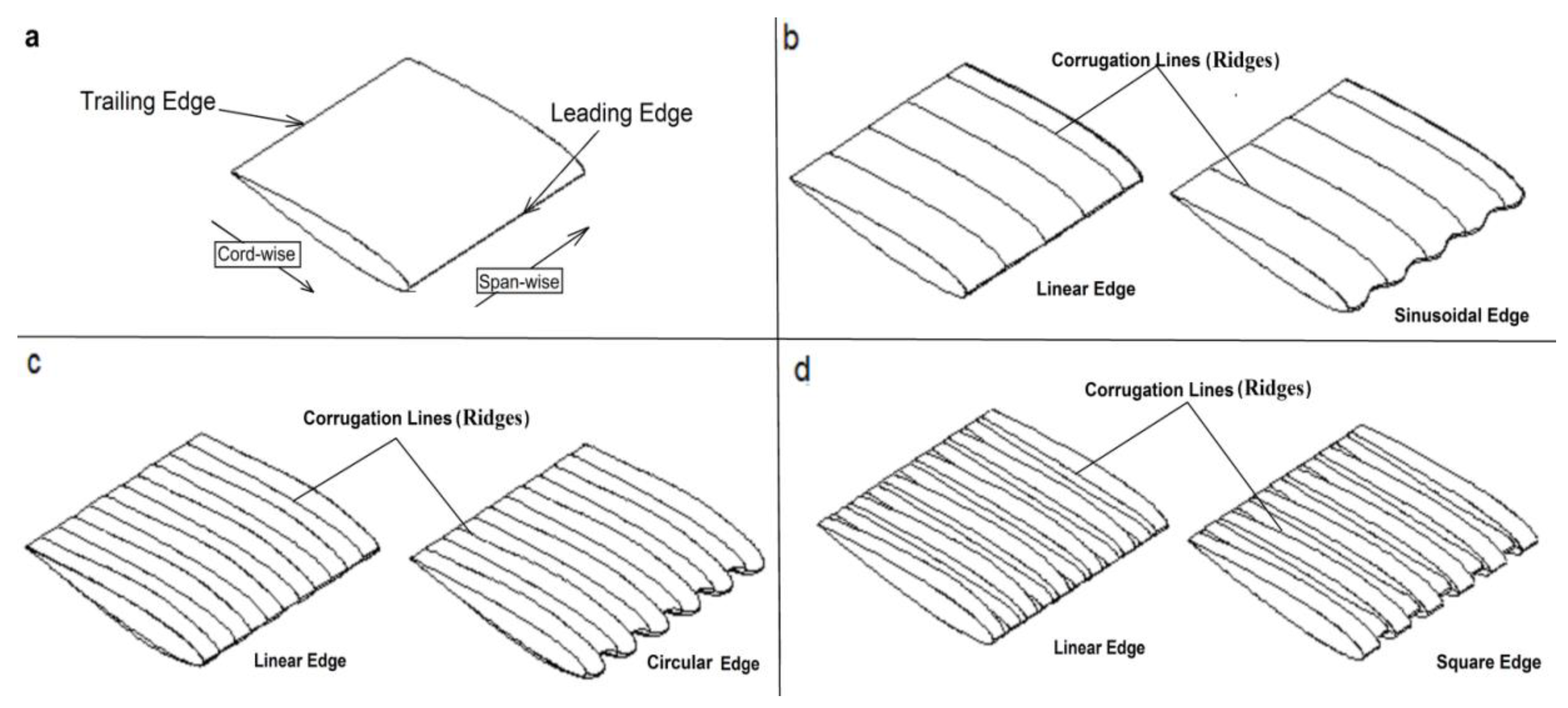
In this section, there are three different flexure hinge designs that are based on an airfoil NACA0012. Changing the profile geometry of the corrugations and leading edges is the main design attributes of the introduced designs as shown in Figure 1.
NACA0012 airfoil is a symmetric airfoil and the most used airfoil in researches and applications. Figure 1a illustrates NACA0012 and the leading and trailing edges, in span-wise and cord-wise directions. Figure 1b–d verifies three main flexure hinge designs with different profiles. Sinusoidal, circular, and square represent the profile geometries of the corrugations. Each design has two configurations, linear and corrugated leading edges. Their chord length, a straight line from the leading edge to the trailing edge of the airfoil, is 1000 mm. Meanwhile, the span is 1000 mm.
In addition, this section covers the full detail design of each flexure hinge design that includes the number of corrugate or the pitch distances and the depth. The finite element simulations of each design are investigated to define the edge-wise, flap-wise, and torsional stiffness and the buckling resistance.

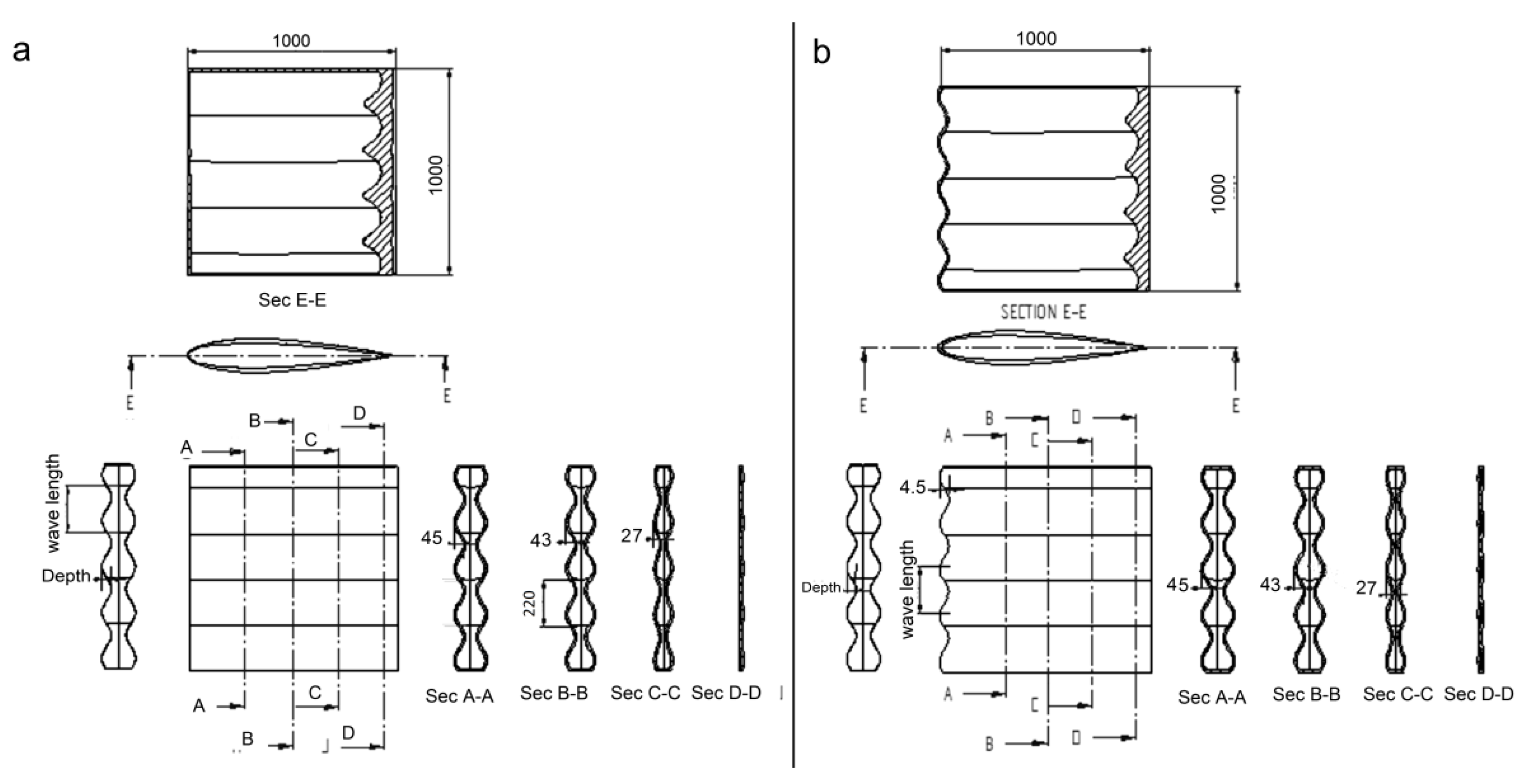
2.1. Sinusoidal Corrugated Design

Figure 2 illustrates the flexure hinge design that bases on the sinusoidal profile geometry. The amplitude or corrugation depth and wavelength of the design are inspired by the wavy shape of tubercles. The amplitude to chord and the wavelength to chord ratios are 0.025, 0.2 respectively. These ratios represent the optimum values of the sinusoidal pattern of the tubercles [9] and will be applied to the sinusoidal profile of the corrugation, the amplitude, and wavelength, reflected on the depth and the number of corrugations, as shown Figure 2. The corrugations direction is along the span-wise of the NACA0012 and the sinusoidal profile follows the ratios of tubercles.
Figure 2a,b illustrates the geometry of the leading edges, linear and sinusoidal. According to the inspiration from the tubercle, the wavelength or pitch distance does not exceed 200mm, along the cord-wise, the corrugations depths vary as shown in Figure 2. To show the interior details in the design, there are sections at the cutting planes (A-A), (B-B), (C-C), (D-D), and (E-E).
The inspired optimum ratios situate at the airfoil apex as shown in Sec-A-A. Toward the trailing edge, Sec (B-B, C-C) verifies the gradual decreasing of the corrugations depth. At the sinusoidal edge configuration, the optimum ratios are located at the leading edge and the airfoil apex as shown in Figure 2b. The interior structure and the hollow cavity of the designs are illustrated by sec (E-E).

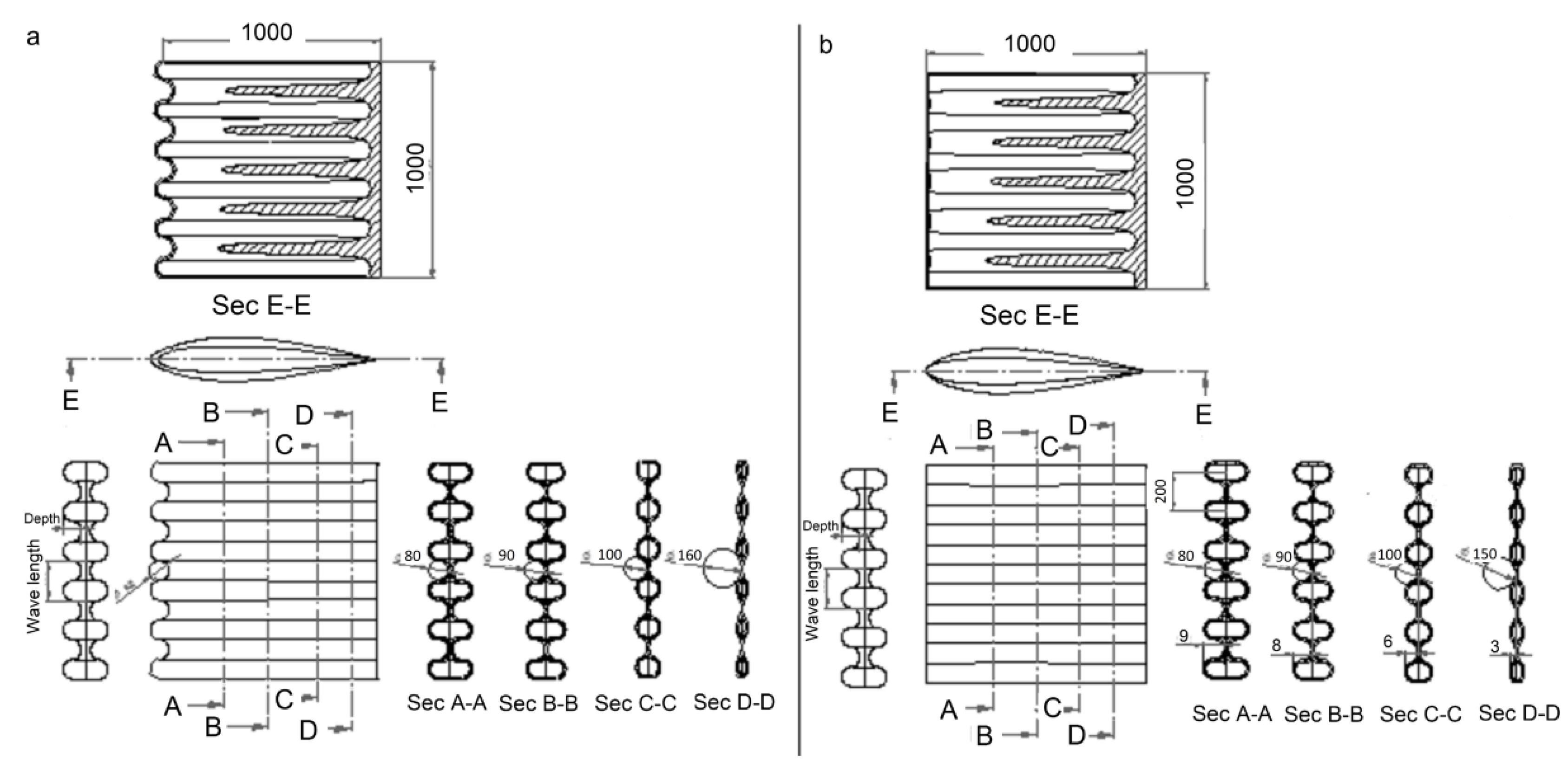
2.2. Circular Corrugated Flexure Hinges Design

Figure 3 illustrates the flexure hinge designs based on the circular corrugated geometry. The main parameters of the circular profile are the wavelength and radius instead of amplitude as the sinusoidal profile. Thus, the diameter to chord and the wavelength to chord ratios are 0.025, 0.2 respectively. There are two configurations, linear and circular leading edges as shown in Figure 3a,b. The pitch distance or wavelength is 200 mm. The maximum depth or height of the corrugations at the airfoil apex is 90 mm. The diameter of the circular profile increases gradually from the apex to the trailing edge as shown in sec (A-A, B-B, C-C). The views of the sections E-E verify the interior structure of the circular corrugation designs.

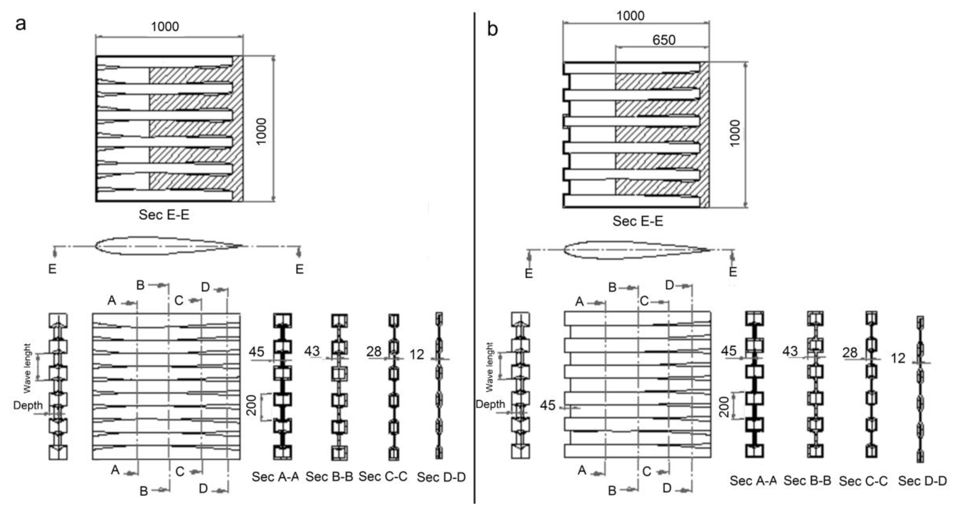
2.3. Square Corrugated Flexure Hinge Design

The third design of the flexure hinge bases on the square corrugation as shown in Figure 4. The main geometrical parameters, number of corrugations, the width and depth of corrugation along the span-wise are investigated in Figure 4. Figure 4a,b illustrates geometries of edges. The ridges of the corrugates are suggested to be have fillet radius not exceeding1 mm to avoid stress concentration. The depth to chord and the wavelength or pitch distance to chord ratios are 0.025, 0.2 respectively.
The depth of the square corrugation varies along the chord-wise direction and decreases until minimized at the trailing edge as shown in Figure 4a,b. The widths of the square corrugation increase at the airfoil edges while the depth decreases as shown in Figure 4b, sec (A-A, B-B, C-C). The views of section E-E demonstrate the interior structure of the design.

3. Finite Element Method Modeling

The finite element method is a very useful tool and has been used to develop wind turbine blades and investigate its behavior [7]. Therefore, the study uses the finite element analysis software Ansys to evaluate the stiffness in terms of three distinctive components; flap-wise, edge-wise, and torsional. The flap-wise and edge-wise stiffness are major to sustain the wind loads and gravity. As the blade increases in size, torsional stiffness can lead to catastrophic collapse due to the flutter instability [11].
To obtain this stiffness with the finite element model, the introduced designs are treated as a cantilever beam and meshed with 25 mm element side length. Consequently, the elements of the model have an aspect ratio close to 1:1 (the ratio between longer dimension to shorter dimension of the element). The shell elements are used in thin-walled hollow structures analysis. Shell281 is the selected element type well-suited for linear, large rotation, and/or large strain nonlinear applications [12]. The geometrical model used polylactic acid PLA material. The elastic property of the material is E = 3.5 GPa and Poisson’s ratio = 0.33.

3.1. Boundary Conditions

Figure 5 shows the applied boundary conditions to define the strength analysis of the introduced design and illustrates the finite element simulation of NACA0012. The edge A of the model is fixed by constraining all degree of freedom and the edge b is free. The type and the direction of the applied loads on the model are defined according to the required stiffness [13].
In the case of pure bending and torsion, the applied forces concentrate at the edge b and the directions are defined according to the stiffness-wise. To get flap-wise stiffness, the force is parallel to the z axis direction as shown in Figure 5a. Meanwhile, the forces will be applied at x direction to get the edge-wise stiffness as shown in Figure 5b. The pure torsion occurs when the applied forces are in different directions along the z axis as shown in Figure 5c. In the case of buckling, the static external uniform pressure applies on the skin of the airfoil instead of the concentrated forces (F) as shown in Figure 5d. The applied force and external pressure are related to the unit load condition to evaluate the static deflection of introduced designs, along the x, y, and z directions [13]. The force (F) reaches to 500 N.

3.2. Stiffness and Buckling Analysis

Figure 6 summarizes the finite element modeling and corresponding deformations for the introduced designs, sinusoidal, circular, and square corrugation. According to the resultant deformations, this section defines the flap-wise, edge-wise, and torsional stiffness, for each design and studies the effect of the leading edge shape. Furthermore, buckling analysis and the Eigen values or the load factors are investigated.

3.2.1. Flap-Wise Stiffness

The XYZ coordinate system of the introduced designs is shown in Figure 6a. The X-axis coincides with the in-plane motion and the Z-axis is directed to the normal plane. The flap-wise stiffness represents the bending resistance around X-axis.
Stiffness is defined as the curvature-to-bending moment ratio in the elastic range or deformation and calculated as the multiplication of Young’s modulus (E) and moment of inertia (I) [13].
Figure 6a illustrates the finite element analysis of the introduced designs when the applied forces (F) reach to 500 N. Accordingly, the vertical deflection along the z axis at the edge-b is defined. The bending rate per unit length was calculated and substituted in the following equation to get the flap-wise bending stiffness.
EI = M d θ / dz  
where E is the elastic modulus, I is the second moment of area, and M is the applied moment, and d θ / dz is the curvature to bending ratio (bending rate per unit length).

3.2.2. Edge-Wise Stiffness

The edge-wise stiffness represents the bending rotation around the Z axis. For calculating this stiffness, two 500 N loads apply to the free end of the model (edge-B) as shown in Figure 5b. As in the previous section, the maximum deformation at the x axis and the bending angle with respect to the global z axis (longitudinal) are defined. Then the bending rate per unit length was substituted in Equation (1) to get the approximate values of stiffness [13].

3.2.3. Torsional Stiffness

For estimating the torsional rigidity, a couple of 500 N m (T) was applied to the edge b as displayed in Figure 5c. Based on the results of the model, the maximum displacement at the edge b was illustrated in Figure 6c. The twist angle and corresponding rate of twist are calculated and substituted in Equation (2) to get the torsional rigidity approximately.
GJ = T d θ / dx  
where G is the shear modulus and ɵ is the twist angle [13].

3.2.4. Buckling Analysis

Buckling is characterized by a common and sudden failure of structures subjected to high compressive stress due to its relatively small thickness. Liquid storage tanks, pressure vessels, and wind turbine blades are applications that are cumbersome from the buckling caused by external pressure [14].
The study used the finite element method to investigate bucking behavior and extracted the eigen-values of the introduced designs that predict the theoretical buckling strength of an ideal elastic structure. Linear buckling analysis is a kind of eigen-value analysis. The frequency values of the finite element analysis represent the load factor for a unit load to estimate the limit of buckling performance.
The corrugated flexure hinges buckles when the linear bending stiffness cannot resist the bending produced by in plane external pressure. Figure 6d shows the buckling load values (FREQ = Buckling load) on the upper lift side for each corrugated design.

3.3. Rapid Prototyping

The study fabricates the introduced design by 3D printer and weighs it. The desktop 3D printer MakerBot Replicator (MakerBot) was used to fabricate the samples of the design using polylactic acid (PLA) filament.The range of Young’s modulus of this type of printed thermoplastic is (3–3.5 GPa) and the tensile strength is (35–50 Mpa). The Rockwell hardness is 88HR [15]. The used solvent is limonene [16]. Figure 7 shows the scaled samples that represent 1:10 size of the introduced designs. By using an electronic scale, the study weighs the fabricated samples to estimate the effect of corrugations profile on the mass.

4. Results

According to the finite element simulation, Figure 5 and Figure 6 illustrate the maximum deformations, DMX, at flap-wise, edge-wise, torsional directions, and buckling results for non-corrugated and the corrugated designs respectively.
The deformations of the pure bending along the Z axis and y axis that represent the flap-wise and edge-wise directions are shown in Figure 5a,b and Figure 6a,b. Figure 5c and Figure 6c simulate the deformed model at the pure torsion. The eigen values of buckling (Frequency) are shown in Figure 5d and Figure 6d.
Table 1 shows the maximum deformation at the flap-wise, edge-wise, and twist directions. Furthermore, the bending angles around the main axis (X-Y-Z) and their rates per unit length and the load factors (Frequency) of linear buckling are investigated. By using Equations (1) and (2), the flap-wise, edge-wise, and torsion stiffness are calculated and tabulated. The weight for each fabricated sample is tabulated in Table 1.

5. Discussion

On the contrary to the previous morphing technologies, the morphology in this study does not relate to or enhance the aerodynamics performance. Folding the blade along span-wise according to the road turns and reducing the transport cost are the morphing objectives. It will be classified as out of plane morphing and large degree of the morph. When the anthropomorphic wind turbine blade arrives at the windy site, workers reinforce the flexure hinges with wires to raise the flap-wise stiffness and sustain the cyclic and fatigue loadings [9]. The three corrugated flexure hinges of the blade represent a small fraction of the whole span as shown in Figure 8. So the study did not consider the aerodynamics effect because the total effective area of the three corrugated flexure hinges represents a very small fraction not exceeding 5%.
In order to serve the anthropomorphic wind turbine, the study presented different designs to enhance the folding along span-wise and sustain the loading conditions. The designs are based on the corrugation with different profiles and leading edges, sinusoidal, circular, and rectangular. To devise the corrugated flexure hinges, the selected profiles were swept along NACA0012 that represented the most extensively used airfoil in research. The other type of NACAs could be utilized in the same methodology to design the corrugated airfoil.
The saw tooth or triangular profile is not covered in this study due to the lowest ultimate deformation and strain compared to the other profiles [17]. Meanwhile, the higher extreme anisotropic behavior and lower effective longitudinal flexural stiffness of the rectangular, sinusoidal, and circular profiles guarantee the higher flexibility and the larger morphing at the span-wise direction [18]. Consequently, the study found the selected profiles are good candidates for the folding wind turbine blades.
The main geometrical parameters of the corrugations are inspired from the tubercle of the whales. The amplitude and the wavelength of the sinusoidal profile and the leading edge resembled the optimum values of the wavy shape of the tubercles and reflected on the number and the depth of corrugations. The other corrugated flexure hinge designs have the same number of corrugations. Comparing to the corrugated skins of the wings [1], the introduced designs have higher corrugated depths that change along the chord-wise direction.
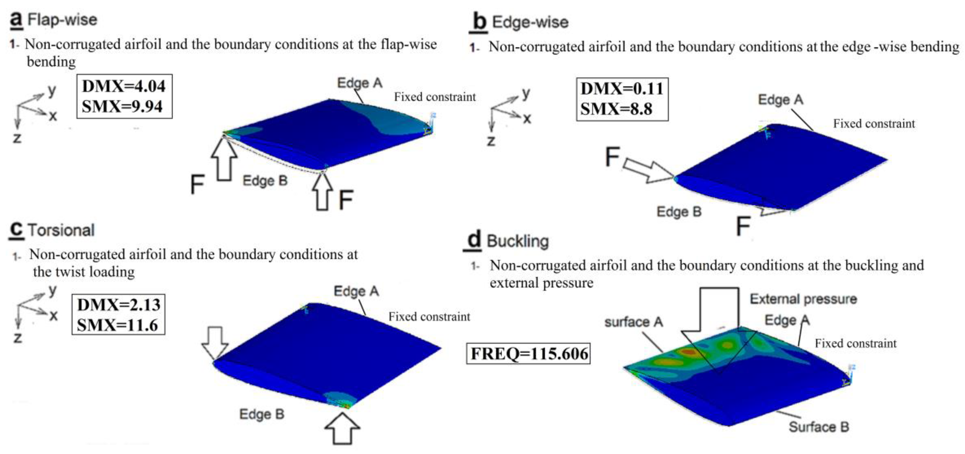
Selecting the most suit corrugated flexure hinge designs depends on crucial strength characteristics of the blade regions through the operation such as stiffness and buckling. Therefore, the study focused on flap-wise, edge-wise, and torsional stiffness to sustain the bending and gravity loads. Due to the buckling possibility at the high chord and span to thickness ratio regions of the blade, the study evaluated the buckling resistance for each deign when sustains external pressure.
The finite element method is the tool used to demonstrate the stiffness and the buckling eigen-values of the flexure hinge designs. The finite element results investigated the effect of the corrugation profile and the shape of the leading edges on the mechanical behaviors. The study focused on the profile type effect on the mechanical strength and did not consider the material. Thus, the used material in the model is plastic, being the closest material to the filament of the 3d printer; nevertheless it is not common using in the wind turbine industry. According to the aspect ratio, the meshing quality is sufficient. The selected quadratic element size gives us optimal combination between of accuracy and computing time [19].
The boundary conditions arrangement and the selected values of the applied loads of the models cohere to the unit load condition that was used to evaluate the static deflection of the wind turbine blade [13].
The corrugation process enhanced buckling resistance considerably instead of using sandwich structure or inherent directional properties of the composite material that represent the effective methods in wind turbine blade [20].
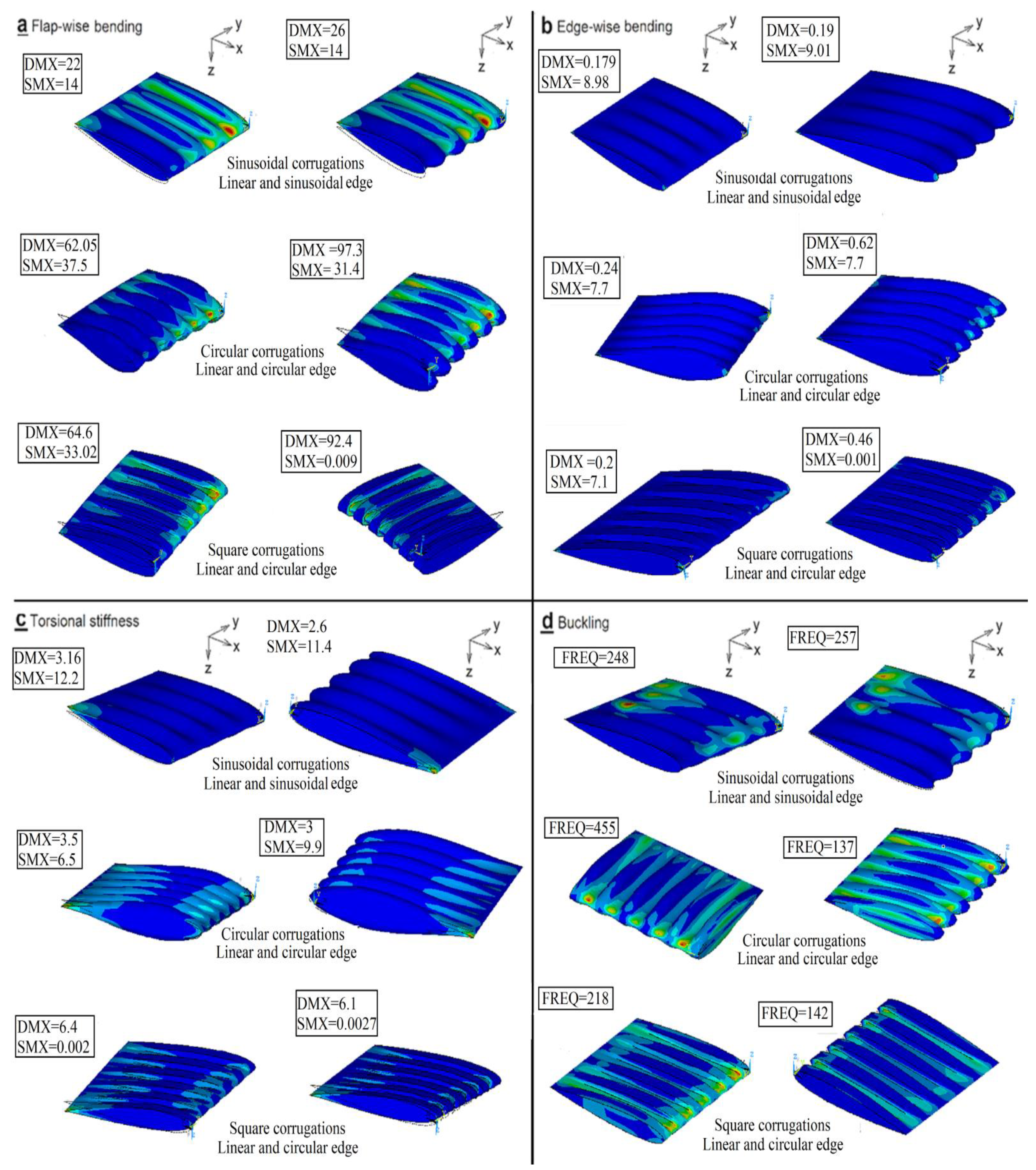
The introduced designs with linear leading edges have higher edgewise stiffness. The shape of edges affected slightly on torsional stiffness. While, along corrugations direction, flap-wise stiffness decreased.
In the case of sinusoidal corrugations design, the geometry of leading edge does not affect the Eigen-values of buckling noticeably. The circular profile with the linear leading edge had the highest buckling resistance. When using the circular edge, the flap-wise and edge-wise stiffness decreased drastically. Minimizing twist stiffness is achieved by square corrugations design.
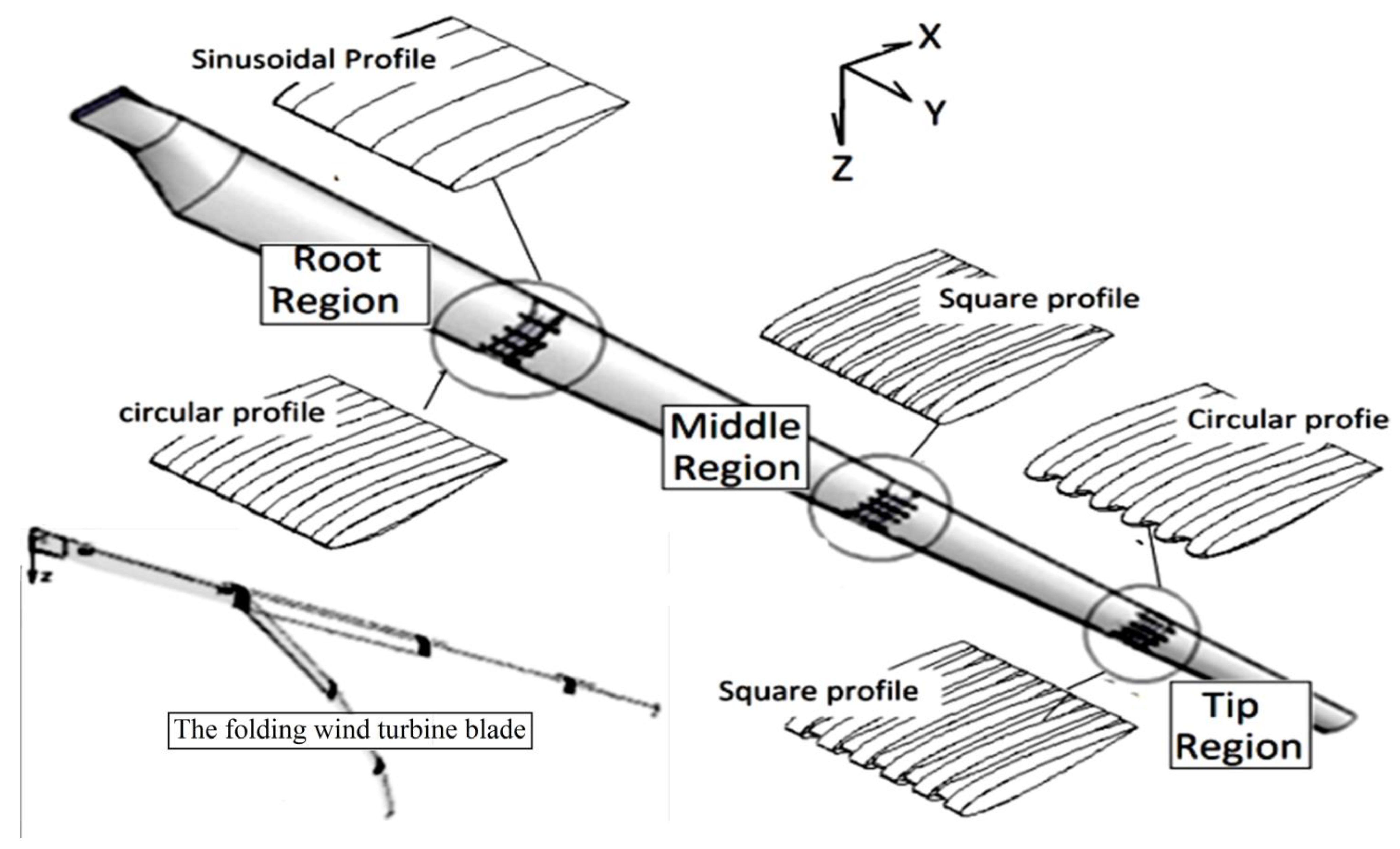
At root region that sustains from higher gravity and buckling possibility, the sinusoidal and circular-corrugated designs with linear edge are recommended due to having higher edge and twist stiffness and buckling resistance. Decreasing the gravity loads and the augmenting the possibility of buckling at the mid-span (middle) region induce the study to select the square corrugation design with linear leading edge. The flap-wise, edge-wise, and torsional stiffness of the blade decreased hugely at the tip of the blade [13]. Consequently, the square and circular corrugated with non-linear leading edge are selected. Figure 8 illustrates the location of the best suit profiles at the anthropomorphic wind turbine blade [10].
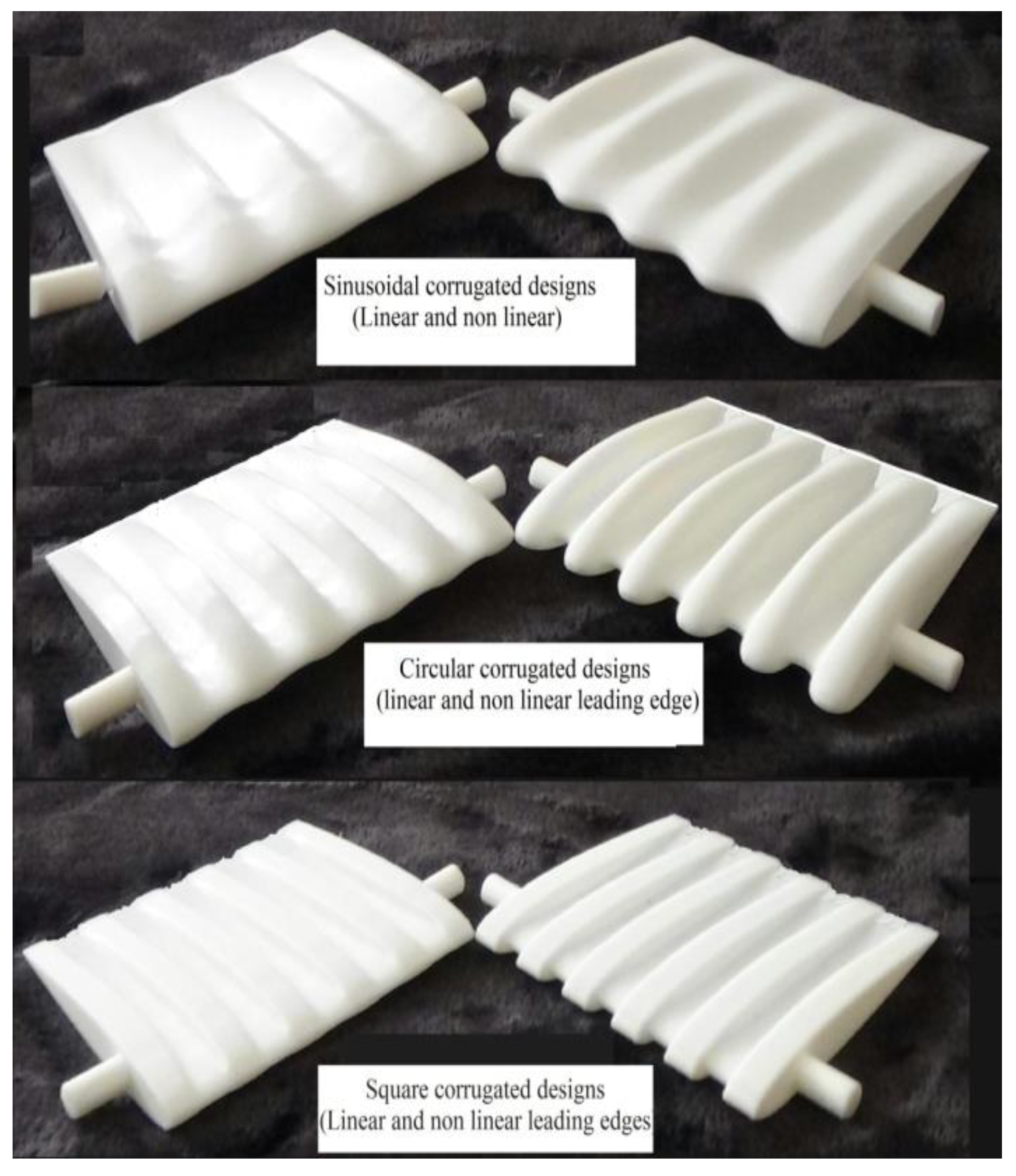
Visualizing the flexure hinge designs is the main purpose of the rapid prototype. It gives a chance to refine the design in the future. Besides, the study assigns the effect of the corrugations on the hinge weight to cohere with the mass distribution along the wind turbine blade.

6. Conclusions and Future Work

The study presented three flexure hinge designs with different profiles and leading edges for the anthropomorphic wind turbine blade. The shape of corrugations is distinguished and the main geometrical parameters are inspired by the tubercle of whale.
The finite element method is used to define the strength characteristics of the designs. Accordingly, the study assigned the most suitable design for the main regions of the blade. At the root region, the study recommended the sinusoidal corrugated hinge with the linear edge. The middle region utilized the other profiles with the linear leading edge. The square and circular profile and non-linear leading edges are selected for the tip region. In the future, the study will focus on the effect of the composite materials on the mechanical strength of each design and build scaled corrugated flexure hinge prototype. Also, the aerodynamics and the fatigue life will be interesting points.

Funding

This research received no external funding.

Institutional Review Board Statement

Not applicable.

Informed Consent Statement

Not applicable.

Data Availability Statement

Not applicable.

Conflicts of Interest

The authors declare no conflict of interest.

References

  1. Sun, J.; Guan, Q.; Liu, Y.; Leng, J. Morphing aircraft based on smart materials and structures: A state-of-the-art review. J. Intell. Mater. Syst. Struct. 2016, 27, 2289–2312. [Google Scholar] [CrossRef]
  2. Lachenal, X.; Daynes, S.; Weaver, P.M. Review of morphing concepts and materials for wind turbine blade applications. Wind Energy 2012, 16, 283–307. [Google Scholar] [CrossRef]
  3. Ameduri, S.; Concilio, A. Morphing wings review: Aims, challenges, and current open issues of a technology. Proc. Inst. Mech. Eng. Part C J. Mech. Eng. Sci. 2020. [Google Scholar] [CrossRef]
  4. Dayyani, I.; Woods, B.K.; Friswell, M.I. The design of a corrugated skin for the FishBAC compliant structure. In Proceedings of the 22nd AIAA/ASME/AHS Adaptive Structures Conference, National Harbor, Maryland, 13–17 January 2014. [Google Scholar]
  5. Kharati-Koopaee, M.; Fallahzadeh-Abarghooee, M. Effect of corrugated skins on the aerodynamic performance of the cambered airfoils. Eng. Comput. 2018, 35, 1567–1582. [Google Scholar] [CrossRef]
  6. Wang, C.; Khodaparast, H.H.; Friswell, M.I.; Shaw, A.D.; Xia, Y.; Walters, P. Development of a morphing wingtip based on compliant structures. J. Intell. Mater. Syst. Struct. 2018, 29, 3293–3304. [Google Scholar] [CrossRef] [Green Version]
  7. Khan, A.; Padhy, C. Aerodynamic and structural analysis of bio-mimetic corrugated wing. Fluid Mech. Res. Int. J. 2019, 3, 61–67. [Google Scholar] [CrossRef]
  8. Uppu, S.P.; Manisha, D.; Devi, G.D.; Chengalwa, P.; Devi, B.V. Aerodynamic analysis of a dragonfly. J. Adv. Res. Fluid Mech. Therm. Sci. J. 2018, 1, 31–41. [Google Scholar]
  9. Thomas, E.; Kumar, V.V.; Dinuraj, V.D.; Lal, N.S. Computational Analysis on Application of Tubercles for the Performance Improvement of Horizontal Axis Wind Turbine. Manuf. Sci. Technol. 2017, 5, 35–42. [Google Scholar] [CrossRef]
  10. El-Sheikh, M.A. An Anthropomorphic Wind Turbine Blade. J. Energy Resour. Technol. 2019, 141, 115001–115025. [Google Scholar] [CrossRef]
  11. Jeong, M.-S.; Lee, I.; Yoo, S.-J.; Park, K.-C. Torsional Stiffness Effects on the Dynamic Stability of a Horizontal Axis Wind Turbine Blade. Energies 2013, 6, 2242–2261. [Google Scholar] [CrossRef] [Green Version]
  12. Pabut, O.; Allikas, G.; Herranen, H.; Talalaev, R. Model Validation and Structural Analysis of a Small Wind Turbine Blade. In Proceedings of the 8th International DAAAM Baltic Conference, Tallinn, Estonia, 19–21 April 2012. [Google Scholar]
  13. Locke, J.; Valencia, U. Design Studies for Twist-Coupled Wind Turbine Blade; SAND2004-0522; National Institute for Aviation Research, Sandia National Laboratories: Albuquerque, NM, USA, 2004.
  14. Yenugula, V.N.; Perumandla, B.; Pinninti, R. Experimental investigation on buckling of GFRP cylindrical shells sub-jected to axial compression. IOSR J. Mech. Civil Eng. 2013, 9, 20–25. [Google Scholar]
  15. Gorji, N.E.; O’Connor, R.; Brabazon, D. X-ray Tomography, AFM and Nanoindentation Measurements for Recyclability Analysis of 316L Powders in 3D Printing Process. Procedia Manuf. 2020, 47, 1113–1116. [Google Scholar] [CrossRef]
  16. El-Sheikh, M.A. Fibonacci-Compliant Finger Design. Int. J. Artif. Organs. 2016, 39, 491–496. [Google Scholar] [CrossRef] [PubMed]
  17. Ghabezi, P. Rectangular and Triangular Corrugated Composite Skins. Fibers Polym. 2018, 19, 435–445. [Google Scholar] [CrossRef]
  18. Golzar, M.; Ghabezi, P. Corrugated Composite Skins. Mech. Compos. Mater. 2014, 50, 137–148. [Google Scholar] [CrossRef]
  19. More, S.T.; Bindu, R.S. Effect of mesh size on finite element analysis of plate structure. Int. J. Sci. Innov. Technol. 2015, 4, 181–185. [Google Scholar]
  20. Cox, K.; Echtermeyer, A. Effects of composite fiber orientation on wind turbine blade buckling resistance. Wind Energy 2014, 17, 1925–1943. [Google Scholar] [CrossRef]
Figure 1. The state of art of the corrugated flexure hinges. (a) NACA 0012 Airfoil without corrugations, (b) sinusoidal profile corrugations, (c) circular profile corrugations, (d) square profile corrugations.
Coatings 11 00635 g001
Figure 2. The detail design and the main dimensions of the sinusoidal corrugated profile. (a) Linear leading edges, (b) sinusoidal corrugated edges.
Coatings 11 00635 g002
Figure 3. The detail design and the main dimensions of the circular corrugated profile. (a) Linear, (b) circular corrugated edge.
Coatings 11 00635 g003
Figure 4. The detail design and the main dimensions of square corrugated profile. (a) Linear edge, (b) square corrugated edge.
Coatings 11 00635 g004
Figure 5. The applied boundary conditions and the FE simulation of NACA0012. (a) Flap-wise, (b) edge-wise, (c) torsional, (d) buckling.
Coatings 11 00635 g005
Figure 6. FEM simulation of the introduced flexure hinge designs at unit load conditions. (a) Flap-wise deformation, (b) the edge-wise deformation, (c) the twist deformation, (d) buckling results.
Coatings 11 00635 g006
Figure 7. The fabricated corrugated hinges by 3d Printer, sinusoidal, circular, and square profile geometry.
Coatings 11 00635 g007
Figure 8. The recommended locations of the flexure hinges at the anthropomorphic wind turbine blade.
Coatings 11 00635 g008
Table 1. The FE results and the calculated flap-wise, edge-wise, and torsional stiffness and weights of the 3d printed samples.
Flexure Hinge DesignNAC0012 without
Corrugation
Corrugated Sinusoidal
NACA0012
Corrugated
Circular
NACA0012
Corrugated
Square
NACA0012
Strength
Characteristics
Edge shape (linear)LinearSinusoidalLinearcircularLinearSquare
Maximum displacement ion in flap-wise direction (mm)4222662976492
The Flap-wise bending angle (°)0.221.251.53.55.53.75.2
The flap-wise stiffness (EI)(N/m2)0.26 × 1060.45 × 1050.38 × 1050.16 × 1050.1 × 1050.15 × 1050.11 × 105
Maximum displacement at edgewise direction (mm)0.110.180.190.250.60.20.45
The edge-wise bending angle (°)0.0060.010.010.0150.0370.010.025
Edge-wise stiffness (EI) (Nm2)9.50 × 1065.70 × 1065.70 × 1063.80 × 1061.50 × 1065.70 × 1062.20 × 106
Maximum twist displacement2.13.12.63.636.46
Torsional twist angle (°)0.250.350.30.40.350.730.7
The torsional stiffness (GJ) (N m2)0.11 × 1060.88 × 1050.95 × 1050.7 × 1050.9 × 1050.38 × 1050.4 × 105
Buckling Eigen values (frequency)115248256455137218142
Weight (gram)2727.5283133.23132
Publisher’s Note: MDPI stays neutral with regard to jurisdictional claims in published maps and institutional affiliations.

