Article

Wear Characterization of Chromium PVD Coatings on Polymeric Substrate for Automotive Optical Components

by
Andresa Baptista
1,2,
Gustavo Pinto
1,2,
Francisco J. G. Silva
1,2,*,
Andreia A. Ferreira
1,
Arnaldo G. Pinto
1 and
Vitor F. C. Sousa
1
1
Department of Mechanical Engineering, ISEP—School of Engineering, Polytechnic of Porto, Rua Dr. António Bernardino de Almeida, 431, 4200-072 Porto, Portugal
2
INEGI—Instituto de Ciência e Inovação em Engenharia Mecânica e Engenharia Industrial, Rua Dr. Roberto Frias, 4100, 4200-465 Porto, Portugal
*
Author to whom correspondence should be addressed.
Coatings 2021, 11(5), 555; https://doi.org/10.3390/coatings11050555
Submission received: 5 April 2021 / Revised: 30 April 2021 / Accepted: 5 May 2021 / Published: 8 May 2021

Abstract

:
The automotive industry is a pioneer in solutions that meet market expectations. However, in the automotive industry, some less environmentally friendly technologies are still used, such as electroplating. Due to legislative restrictions in several countries, thin coatings made in a vacuum have been replacing coatings traditionally made by electroplating, mainly in decorative terms. This work is more focused on the use of these coatings made in vacuum for optical applications, namely on headlights and exterior backlit components. Although these components are protected during the period of use, there may be situations of contact during the assembly of the components or their repair, necessary to safeguard and to ensure that these coatings have the scratch and wear resistance needed to withstand any treatment deficiency during the operations referred to above. Therefore, this work is essentially focused on the study of the wear resistance of Cr coatings made by PVD (Physical Vapour Deposition) on polymeric substrates. To this end, the coatings previously studied have now been subjected to micro-abrasion tests, with a view to assessing their wear resistance. For this purpose, alumina abrasive has been used, and the wear mechanisms observed in the coatings were studied. The abrasion and scratch tests showed that the most stable film has the one provided with 10-layers, showing greater wear resistance as well, greater adhesion to the substrate and less cohesive failures in the performed tests. Given the nature of the substrate and the coating, the results obtained are very promising, showing that these 10-layer Cr thin coatings can overcome any careless operation during manufacturing, assembly and repair processes, when applied in lightning or backlit components in motor vehicles.

1. Introduction

Innovation is one of the main pillars of the automotive industry, which, due to the high competitiveness between brands, is one of its main selling points. OEMs (Original Equipment Manufacturers), due to that competition, also seek to keep up with market trends and one of these is consumers being increasingly aware of everything that concerns the ecological footprint of the products they purchase, paying attention to the way in which producers conduct the development of their products, and the impact that this production has on the environment [1]. The coatings made by PVD (Physical Vapor Deposition) represent a manufacturing technology with a very low ecological footprint, presenting significant advantages over electroplating coatings [2,3]. This type of coating has known applications in several fields and types of industry, such as: biomedical implants [4,5], medical devices [6,7], solar energy cells [8,9], low friction applications [10], generic automotive applications [11,12], thermal barriers [13,14], cutting tools [15,16,17,18,19], plastic injection molds [20,21,22,23], and stamping dies [24,25,26,27]. However, lightning systems are mainly based on conventional or hybrid processes [28,29], and are not completely environmentally friendly.
Due to the low temperature supported by polymers, the deposition of thin coatings by advanced vacuum processes has always known some limitations, having encouraged researchers to lower the deposition temperatures used in the PVD process. In addition, the polymers are non-conductive, which brings new challenges to the deposition process, such as the use of RF (radio frequency) to the detriment of the usual DC (direct current) systems [30]. Sometimes, the adhesion of coatings to the polymeric substrate has also presented additional challenges, requiring the pre-treatment of substrates, with a view to improving adhesion, a fundamental parameter for the good performance of the coating [31]. However, several studies have been carried out in the application of PVD coatings in polymers, and even in the evaluation of the adhesion and wear resistance of these coatings. Based on ABS (Acrylonitrile Butadiene Styrene) substrates, Qian et al. [32] investigated the adhesion of thin Ni coatings carried out by PVD sputtering, considering the parameters used in the deposition. By conducting tests on micro-scratch equipment, it was possible to find that the greater the ionization energy used in the process, the later the critical failure in the coating occurs. Through a broader study, they investigated different levels of plasma applied to the substrate surface, increasing its surface energy. In this way, it was possible to analyze the influence of the critical load that the coating can withstand depending on the levels of plasma to which the surface had been exposed, verifying that the exposure to a more intense plasma increased the surface energy, improving the adhesion between Ni coating and PC (Polycarbonate) substrate. Based on polymeric substrates reinforced with carbon fiber, Coto et al. [33] investigated the adhesion, erosion behavior and wear resistance of multi-layer Ti/TiN coatings, with global thicknesses between 1.5 and 11 µm. The authors found that the main failure mechanism observed was the delamination of carbon fibers, and that the coatings were more resistant to sand erosion with a greater thickness.
Due to problems previously identified using Cr-VI in electrodeposition processes, the REACH program (Regulation for Registration, Evaluation, Authorisation and Restriction of Chemicals) developed at the European Union has as its focus the abolishment of this process for the deposition of decorative Cr coatings. Thus, Vergason et al. [34] investigated the properties of Cr deposited by DC sputtering with a view to its application in the automotive industry. Subsequent evaluations carried out by several OEMs in the automotive industry confirmed that the investments obtained in vacuum had a nanoscale, in contrast to the thickness traditionally obtained by electroplating, presenting extremely interesting characteristics for the applications in question. CrN coatings have also been proven to be a great alternative to traditional Cr coatings, made using electroplating. Indeed, Zhang et al. [35] investigated this type of coating deposited by PVD HiPIMS (High-Power Impulse Magnetron Sputtering) on ABS substrates, although it has been found that these coatings can be subject to cracking when subjected to intense thermal cycles. However, carrying out a comparative study with CrN coatings deposited by HiPIMS and by DC magnetron sputtering, these authors concluded that any of these processes can produce coatings able to easily replace the coatings previously obtained by electroplating. In the meantime, the authors also observed that coatings deposited by HiPIMS presented better mechanical and corrosion resistance than coatings obtained by DC magnetron sputtering. In recent years, the market has been requesting the study of thin metallic coatings deposited on polymeric substrates, presenting optical properties. In this way, Singh et al. [36] investigated the magnetron sputtering PVD deposition of aluminum coatings on PC substrates, which demonstrated a high reflectance (96%) when tested within the wavelength range of 250 nm to 2500 nm. Ferreira et al. [37] also studied the optical properties of Cr coatings deposited by PVD sputtering on PC substrates, using different coating thicknesses. Coating adhesion, when tested through scratch-tests, was excellent, with the scratches being carefully observed by SEM, and showing some very small conformal cracks resulting from the substrate deformation under the loaded indenter. The roughness was also assessed using an AFM technique, having obtained Ra values of around 3 µm, which tended to decrease when the coating thickness increased. Given that the main application in view was, as in this article, the use of Cr coatings by PVD in backlit parts for the automotive industry, the transmittance obtained was not the most desirable, but some parameter adjustments seem to be sufficient to produce the desired effect.
The wear resistance of thin coatings can be assessed using numerous test configurations, depending on the load to be used and the type of contact which is close to the one that better represents real work conditions [38,39,40,41]. Of this great diversity of configurations, two stand out: pin-on-disc [42,43,44,45] and ball-cratering [46,47,48,49]. Within the ball-cratering tests, there are still two different configurations [50,51], using distinct ways of applying the load to the coated sample. Ball-cratering tests, also known as rotary ball micro-abrasion tests, have probably been used less frequently than tests of pin-on-disc configuration, but they have some very interesting characteristics, such as: (a) the test allows to evaluate the wear, but also to measure the thickness of the coating; (b) the abrasion effect is accelerated, through the introduction of particles in the contact; (c) the equipment is light and economical; (d) it presents a high flexibility of test conditions, varying the load, the material of the ball, the size and type of abrasive, the rotation speed of the ball, or the flow of abrasive; (e) it is easy to operate and the results are extremely reproducible; (f) it is widespread in the scientific community and well dissected in terms of analyzing the produced results [52,53,54,55,56]. After the tests have been carried out and the duration considered to be the most appropriate for each case, the produced craters were measured, with a view to calculate the wear coefficient (in cases where the crater is circular and homogeneous). These measurements are usually performed using SEM (scanning electron microscopy) [57,58]. The texture of the center of the craters, as well as the edges of the entry and exit of the abrasive particles, must also be carefully observed, to characterize the wear mechanism induced by the abrasive particles: two-body abrasion (grooving) or to three body (rolling). These phenomena are well defined in the literature and can be seen in Figure 1 [47,50,55].
In this work, it was intended to characterize the wear resistance of Cr coatings deposited by PVD sputtering on PC substrates, analyzing the wear mechanisms involved, to verify their ability to resist the existing manipulation during the assembly of lightning and other backlit devices usually applied in motor vehicles.

2. Materials and Methods

2.1. Material

2.1.1. Characterization of the Substrate Material and Corresponding Geometry

In this work, a polycarbonate (PC) polymeric substrate, produced by injection molding was used. This polymer has some interesting properties, such as its impact resistance, good electrical properties, and dimensional stability, which is also very good. Its characterization is shown in Table 1.
For the deposition process, the samples were prepared with a flat geometry with dimensions of 147 mm × 54.5 mm and 3 mm thickness. The selected geometry became easier in its fixation in the reactor and in its characterization after the PVD deposition process. This went through a surface preparation process using an isopropyl alcohol container. After cleaning, the samples underwent a process of depositing the chromium (Cr) coating by Sputtering, layer by layer, with intermediate cleaning processes, as recommended by the PVD reactor manufacturer. After completing the deposition cycle, the parts were properly characterized. For the micro-abrasion tests, a cross-section was made on the back of the samples with a diamond cutting disc to cause a brittle fracture on the side of the film. Subsequently, the samples were cut using liquid nitrogen, to geometry of 27 mm × 24 mm, thus ensuring its fixation on the tribometer.

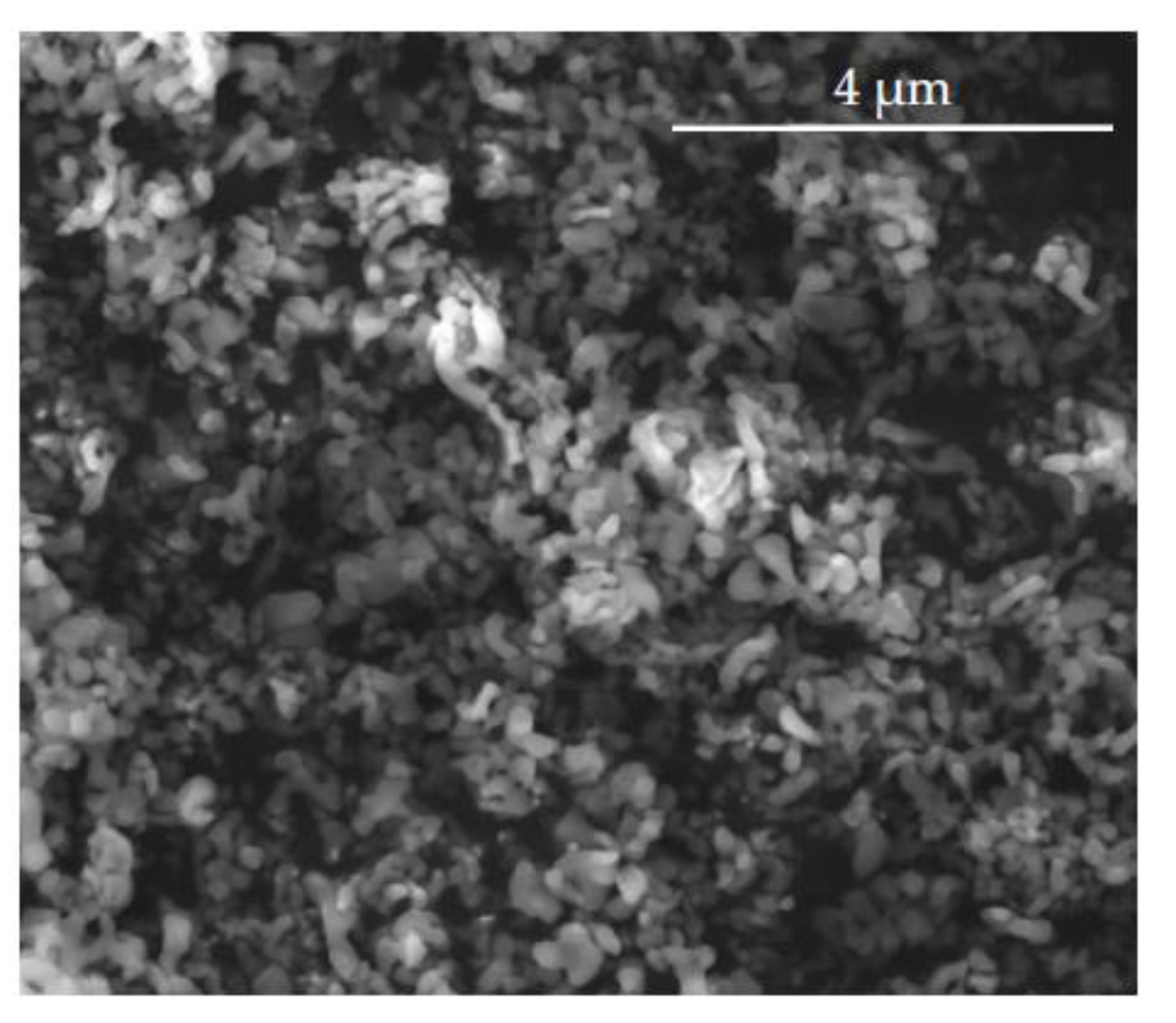
2.1.2. Abrasive Particle Characterization

The abrasive used in the micro-abrasion tests was MicroPolish alumina Powder-Deagglomerated Alpha (Al2O3) and was composed of particles with 1 µm size. This kind of abrasive was selected due to the nature of the coating and substrate. Indeed, other kinds of abrasive are available and are currently used by other researchers. It is well-known that small diamond particles produce well-defined craters, which are extremely easy to measure, independent of the hardness of coatings and substrates. However, diamond particles, as well as SiC ones, present a high hardness, which is not the best option to test relatively soft coatings and substrates. Thus, the choice fell on alumina, because it is relatively soft when compared to the other abrasives usually used in this type of wear test. Therefore, the abrasive was observed via SEM (FEI Quanta 400FEG, Field Electron and Iron Company, Illsboro, OR, USA), enabling an analysis of its morphology since it plays an important role in the wear tests, as shown in Figure 2.
The image shows an agglomeration of abrasive particles, which avoids the measurement of the abrasive particles with the intended accuracy.

2.2. Methods

2.2.1. Coating Deposition Process

The coatings of the samples were obtained using a PVD deposition equipment from Kolzer-MK63 (Kolzer, Milan, Italy). This equipment is intended for industrial production, for high volumes, enabling short cycle times, as well as covering a high number of parts per cycle. Its available technologies are Sputtering, Thermal evaporation, and Plasma PECVD. In this work, only the Sputtering technique was used. The reactor has a power capacity of 10 kW and an ionization energy of 1500 kJ, and its deposition chamber has a volume of ø1600 mm × 1450 mm. The parameters that remained constant during the deposition process were as follows: the type of gas used, argon with 99.998% purity, the gas flow rate (440 sccm), and the polarization (−25 V). Chromium (Cr) targets were used with dimensions of 120 mm × 1000 mm × 16 mm and a weight of 14.20 kg for each one. Regarding its chemical composition, it has between 99.8–100% Cr, which allows it to be defined as extra pure. The chemical composition of the Cr target can be seen in Table 2. Each coating was produced looking for a certain number of layers. Thus, 6, 8 and 10 layers were deposited, to achieve the desired optical effect (metallization) and the transmittance necessary to the automotive industry [37].
Since the deposition was made in stages, i.e., layer by layer, the plasma is used to clean the chamber between stages. It should be noted that, during the cleaning period, to extend the useful life of the targets, the shutters covered the targets in order to protect them and avoid deposition, allowing partial cooling of the power system. The deposition of each layer lasts for 4 min, and the cleaning process between the layers lasts for 2 min.

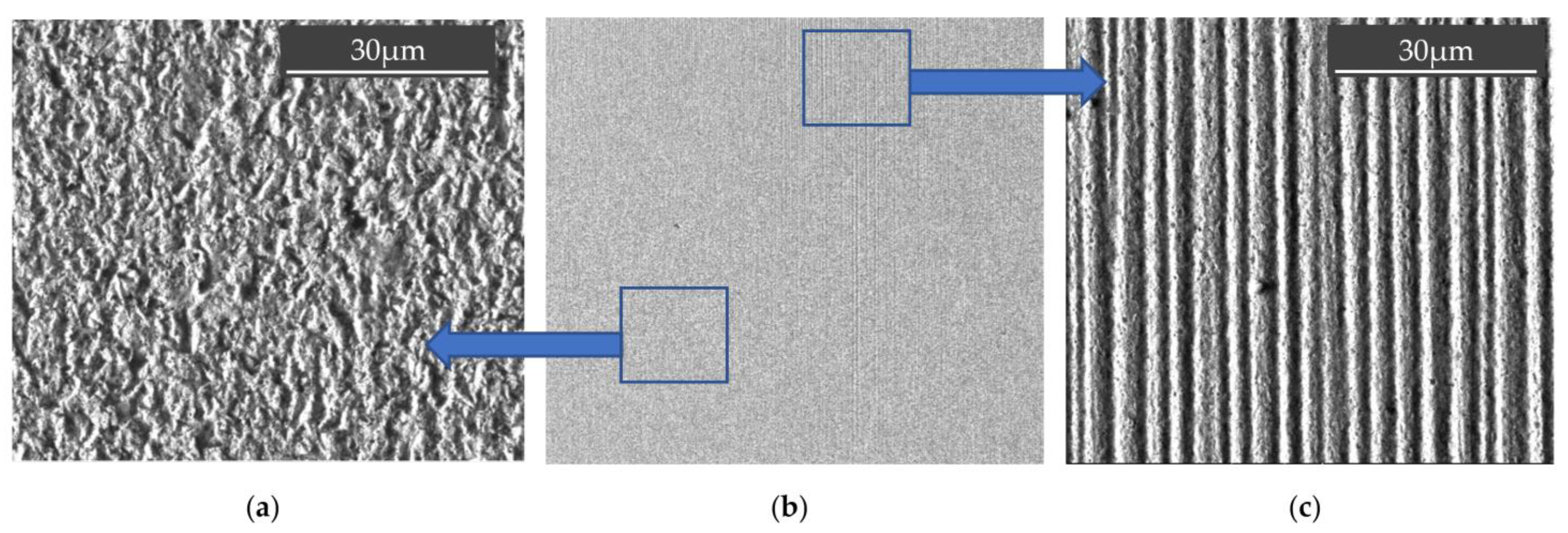
2.2.2. Morphology and Thickness Analysis

After the deposition process, the samples were prepared to determine their thickness. For this, they were partially cut with a diamond cutting disc, and were subsequently dipped in liquid nitrogen for 20 min. Then, they were carefully broken in cold state by mechanical means, allowing a brittle fracture. This methodology avoided mechanical deformations of the substrate and coating, close to the broken area, without disturbing the evaluation of the coating’s thickness. To measure the film thickness from the different samples, a scanning electron microscope FEI Quanta 400FEG-SEM (Field Electron and Ion Company, Hillsboro, OR, USA) was used, provided with an EDAX Genesis X-ray spectroscope (EDS-energy dispersive spectroscopy) (FEI, Hillsboro, OR, USA), with a resolution of 1.2 nm. A working distance of approximately 10 mm was used in electron scattered mode, with a beam energy of 15 keV.

2.2.3. AFM Roughness Analysis

To assess the roughness of the surfaces, the samples were prepared using the same procedure previously described to prepare the micro-abrasion samples, now using 10 × 10 mm2 area. For this purpose, an atomic force microscope (AFM), VEECO-Multimode (VEECO Instruments, Ltd., Woodbury, NY, USA) was used, which is equipped with a Nanoscope IVA controller and NanoScope® software (version 6.13, Bruker Portugal, Oeiras, Portugal). The following parameters and characteristics were followed: analysis area (XY plane): 20 × 20 μm2; maximum vertical displacement (in z): 6 μm; resolution: 16 bits; curvature radius of the indenter: 7 nm; analysis modes: contact, intermittent contact, and non-contact. The probe used in the analyses was of Silicon Nitride with K = 0.32 N/m. For the evaluation of the roughness, the following parameters were considered: the arithmetic average roughness of the surface (Ra), the total height of the assessed profile (Rt), and the root mean square deviation of the assessed profile (Rq), according to EN ISO 4287 [60].

2.2.4. Adhesion Analysis

To assess the adhesion of the coating to the substrate for samples with 6, 8, and 10 layers of coating, scratch tests were carried out using a CSM Revetest® scratch tester (CSEM, Neuchatel, Switzerland), provided with an acoustic emission detector, according to the BS EN ISO 20502:2016 standard [61]. The scratch test allows quantifying the normal adhesion load between the film and the substrate in cohesive (Lc1) and adhesive (Lc2) failure modes. To obtain more accurate results, six scratches were carried out on each coating. Bearing in mind that the polymeric substrate used was very soft, the scratch tests using Rockwell C diamond indenter I-119 model to produce the scratches, tracked the following parameters: applying an increasing normal load from 0 N to 100 N, the travel speed of the indenter was 3 mm/min, and the final displacement was 10 mm. The scratch results were analyzed, by SEM, in order to correlate the distance covered by the indenter under normal load and thus understand the type of failure that occurred, cohesive or adhesive, as well as the critical load responsible for the failure.

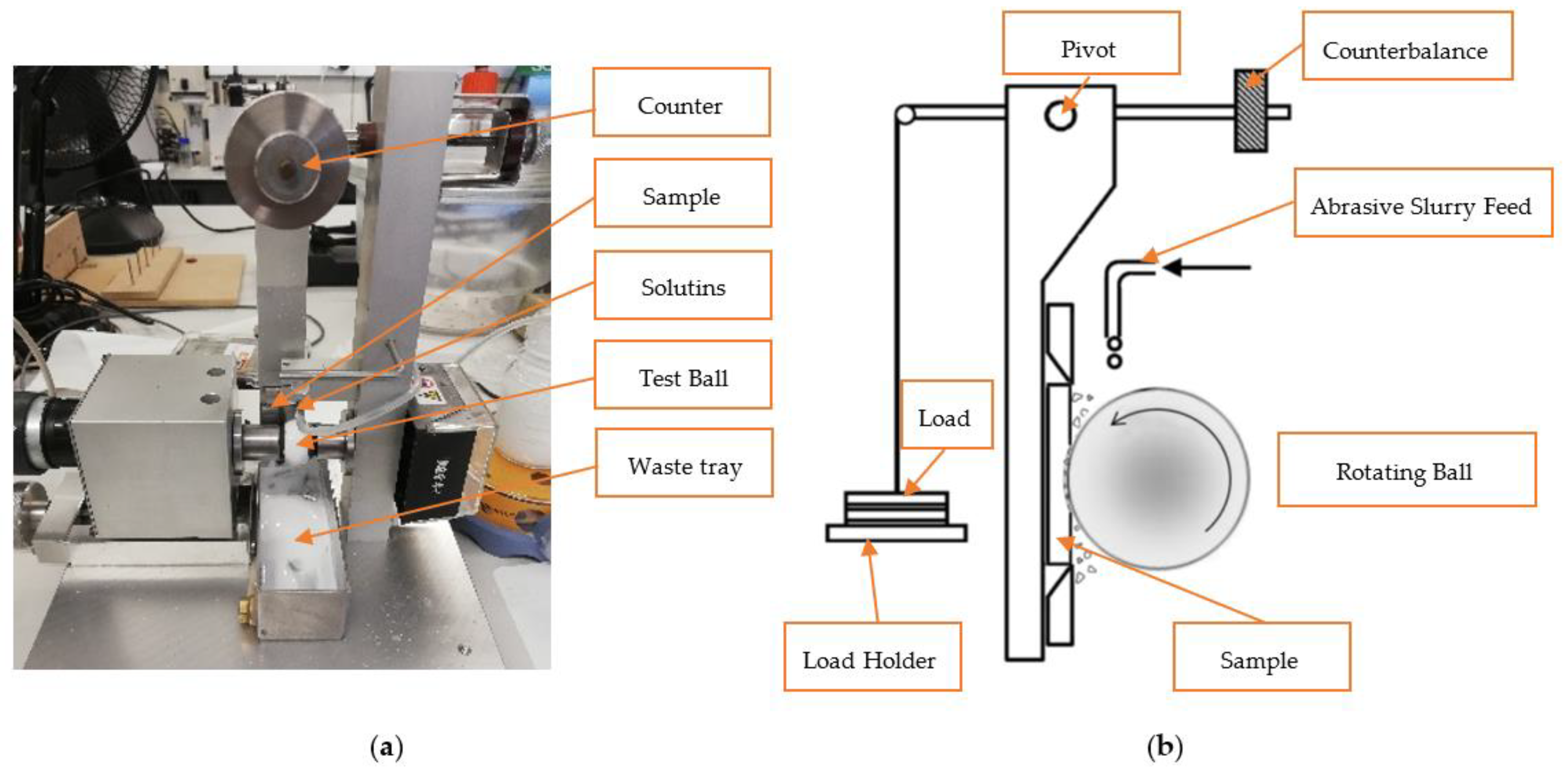
2.2.5. Micro-Abrasion Test

The micro-abrasion test by rotating ball was used to perform tribological tests. The equipment used in the wear tests was the PLINT TE66 (Phoenix Technology, London, UK) Micro-scale Abrasion Tester, the setup of which can be seen in Figure 3. To carry out these tests, the samples were prepared, as already described in Section 2.1.1, with dimensions of 27 × 24 mm2, so that they could fit in the existing holder, and thus guarantee its fixation. The processing parameters for these tests were as follows: 0.2 N load; 80 rpm speed; 50, 100; and 200 rotation cycles. A slurry was prepared containing 35.4 g of 1 µm alumina powder abrasive in 100 mL of distilled water.
In the test, 25 mm AISI 52100 steel balls usually used in rolling bearings were used. The balls were cleaned in an ultrasonic acetone bath for 10 min to wash the surface of the possible protective lubricant layer. After cleaning, they were immersed in a NITAL 4% solution for 60 s to increase their surface roughness. Thus, the micro craters created by etching process will allow a better drag of the abrasive particles, according to the authors [47,50].
The wear made by the tribometer is achieved through the slurry, where the ball is subjected to a normal load, the particles carry that load and are moved through the contact, due to the movement created by a motor shaft at a pre-defined rotational speed. Thus, the particles contained in the slurry will be dragged through the contact. The resulting craters in the samples were subsequently studied by SEM to assess the wear behavior and understand the amount of material lost in each test. The ImageJ® software (version 1.53g) was used to assess the average diameter of the craters; however, this measurement has an associated error, as it was obtained through the crater contour resulting from SEM, which does not correspond perfectly to the real dimension. The wear coefficient was not calculated since the heterogeneity is very large between the coating (chromium) and the substrate (polycarbonate), regarding its hardness and other mechanical properties, as well as because these materials generate craters that end up not presenting a uniform diameter.

3. Results and Discussion

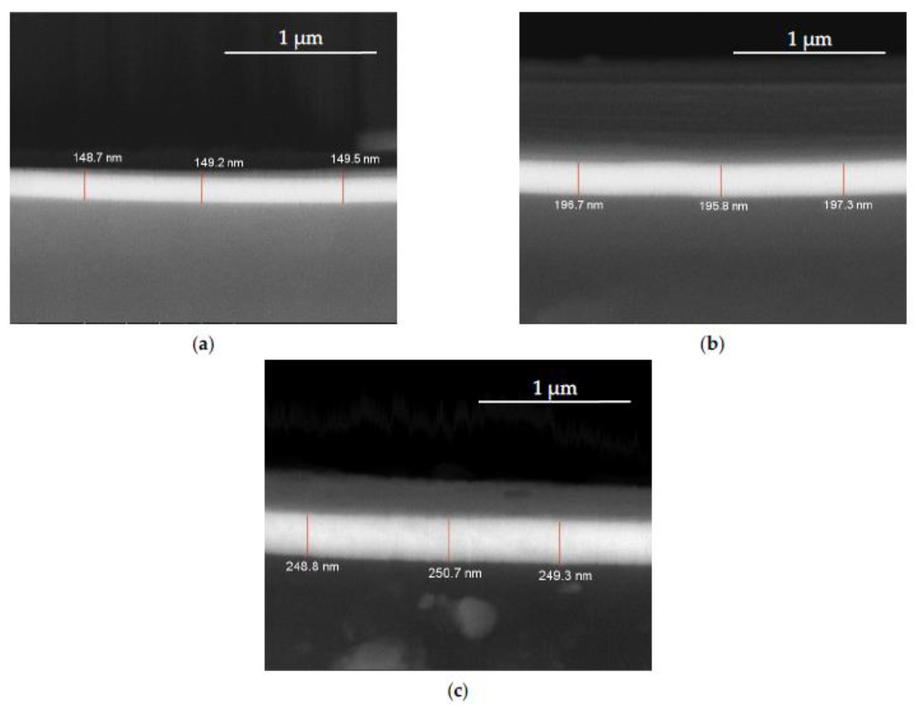
3.1. Coating Morphology and Thickness

The experimental methodology used, which includes the deposition of several layers of the same material (Cr), can be considered as a multilayer system, although this term is commonly used in the deposition of multilayers of different materials and different thicknesses. In this way, the multilayer classification was adopted for the studied coating considering its deposition method. It should be noted that XRD analyses were performed to investigate the coating structure and residual stress; however, these analyses do not produce valid results due to the extremely reduced coating thickness (lack of enough material volume). Thus, a previous characterization of the morphology and thickness of the coating was performed by SEM, as described in Section 2.2.2. The images in Figure 4 show, as expected, as a greater number of layers is deposited, the linear increase in the thickness of the coating occurs. Figure 4a–c shows the evolution of the thickness increase for samples with 6, 8, and 10 layers. Evaluating the evolution of the thickness between layers, it is possible to state that each deposited layer adds approximately 25 nm of thickness. It should be noted that, to ensure repeatability and confidence in the obtained results, 8 samples were observed for each deposition of 6, 8, and 10 layers under the same conditions. Thus, Table 3 shows the average values and the respective standard deviations of the thicknesses measured.

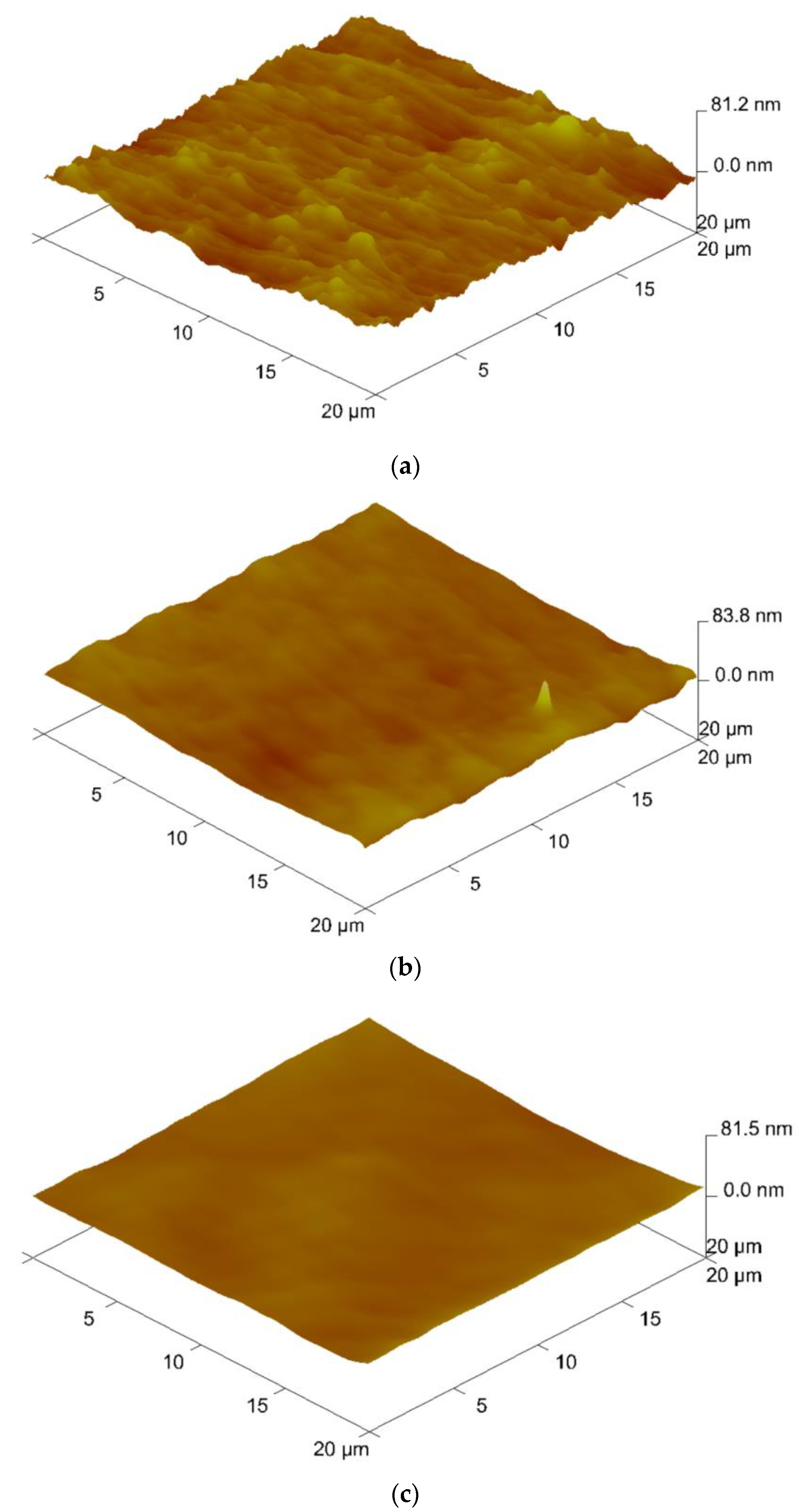
3.2. Roughness Results

The surface roughness of the samples was obtained using AFM technique. In Figure 5a–c, the decrease in surface roughness occurs with the increase in the number of deposited layers. It is denoted that a homogenization of the surface makes it uniform with a smaller number of scratches or valleys. In Table 4, the decrease in roughness is quantified, showing that the value of Ra decreases according to the increase in the number of layers. Observing the exposed values of Rt and Rq, it can be stated that with the evolution of the process, the deposition is made preferably in the valleys, attenuating the difference of height between peaks and valleys, thus reducing the roughness. Thus, the surface roughness Ra decreased by 21.5% from 6 to 8 layers and decreased by 41% from 8 to 10 layers.

3.3. Adhesion Evaluation

The scratch tests were carried out following the parameters described in chapter 2. In this sense, the sliding grooves resulting from the contact of the indenter with the respective samples were obtained, which can be seen in Figure 6. In this figure, there are no relevant phenomena. There is also little conformal cracking in semicircles, Figure 6a,c,e, due to the arc deformation induced by the indenter tip shape. These cracks have a geometry that accompanies the accumulation of material in front of the indenter, not putting the adhesion of the coating at risk. These results are in line with conclusions obtained by other authors who have studied adhesion to polymers substrates [32,62].
In general, the samples showed good adhesion, which is confirmed by the obtained images. In Figure 6b,d,f, it is observed that by increasing the number of layers the lateral cracking significantly decreases. Figure 7a shows, in detail, the morphology of the material after being subjected to the scratch test, it being perfectly visible that the film adhered to in the substrate, which was confirmed by EDS, Figure 7b,c, clearly shows the presence of Cr and a small peak of C (substrate).

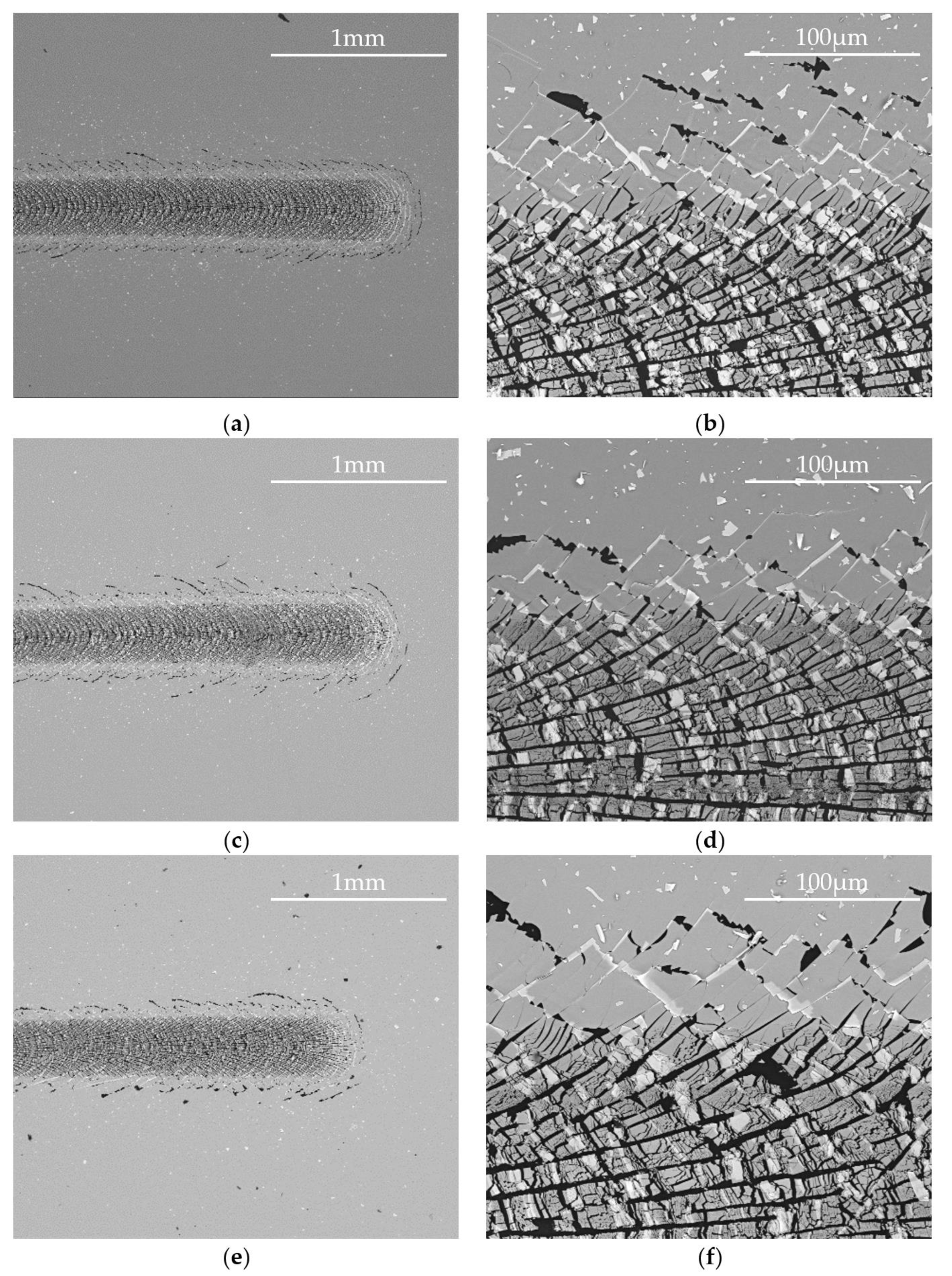
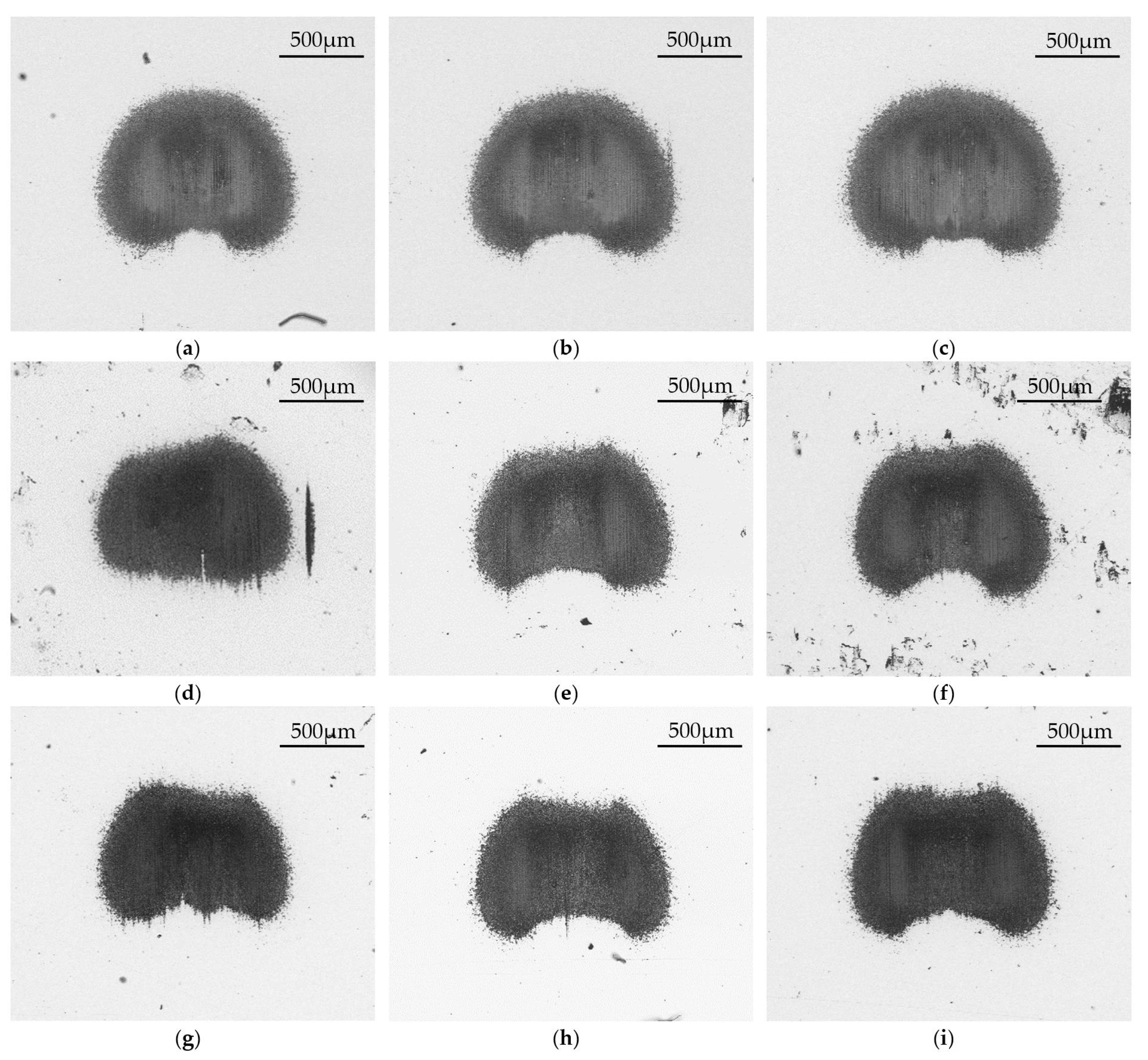
3.4. Micro-Abrasion Analysis

According to the procedure described in Section 2.2.5, it was possible to check the abrasion resistance of the coatings for the different Cr number of layers, as well as the wear mechanisms involved in the abrasion process. For the analysis of the craters, their diameter was measured by SEM. The different wear mechanisms are related to the way the abrasive particles are moved through the samples’ surface; namely, three-body abrasion or two-body abrasion. Indeed, the wear mechanisms will deserve better attention than the volume of material removed, as the craters are not perfectly circular and do not allow for an accurate measurement of the crater diameter. Given the nature of the substrate and the low film thickness, it was not possible to clearly define the internal and external craters. Furthermore, the craters do not present a well-defined circular pattern. Due to the irregular shape of some craters, it was decided to not consider the wear coefficient, as it is difficult to accurately measure the crater area. Thus, the focus of this work is on the wear mechanisms involved in the abrasion of the Cr multilayer coating.
Figure 8 shows the geometry of the craters produced by the tribometer. The irregular shape of the craters is common in certain materials’ substrates and coatings, depending as well on the abrasive used in the test [63]. A detailed analysis of the obtained craters allowed for the observation that alumina tends to agglomerate predominantly at the exit area of the contact. There is an accumulation of alumina abrasive particles that reduces the size of the crater, making it irregular. Additionally, this accumulation tends to diminish the aggressiveness of the other abrasive particles. Below is a brief analysis of the craters’ images observed in Figure 8, allowing us to draw some conclusions about the resistance of the developed coatings.
As the substrate is very soft, the application of the load will cause a micrometric deflection of the surface, creating a “wave” around the contact point, which prevents proper contact in particles’ entrance and exit areas. Due to the tendency of particles to agglomerate, they start to become compacted in these areas, promoting a renewal of the particles in the surface layer. This prevents that moving particles from causing abrasion following a two-body (grooving) mechanism in the substrate, through the formation of a layer that prevents the effective action of the abrasive particles in those areas. This induces the creation of irregular craters, with wear gaps in the areas of entrance and exit of abrasive particles in the contact, as can be seen in all the images in Figure 8.
In the lateral areas of the craters, the same also happens; however, the agglomeration of alumina particles is less accentuated, due also to a greater flow of slurry. Thus, the crater has a greater tendency to grow laterally, where there is no agglomeration of particles, than in the entrance and exit zones, due to a greater compression of the abrasive particles. According to Sánchez-Huerta et al. [64], the use of a greater load in micro-abrasion tests leads to more regular and circular craters. However, in this case, the substrate being soft, the use of a higher load might not be the best way to solve the problem, as the deflection of the substrate would be even more pronounced.
It is concluded that, due to the low hardness of the substrate, micro-abrasion tests will always tend to promote the formation of irregular craters, unlike what is usually verified in hard materials.
In Figure 8a–c, it is possible to observe a light evolution of the crater area with the increase in the number of cycles. Furthermore, the external ring showed in the craters tends to diminish with the increase of the number of cycles imposed in the test, but the evolution is moderated. This can be attributed to the low thickness of the film having achieved the rupture of the coating. However, after the rupture of the coating, the wear tends to become stable, and the evolution is lower. Indeed, the external ring created by the wear acquires a critical area able to better support the load carried out by the abrasive particles.
In Figure 8d–f, the craters have approximately the same area and an identical geometry; however, the area corresponding to the alumina raises with the increase in the number of cycles. Finally, in Figure 8g–i, the craters present the geometry mentioned above. A more detailed EDS analysis was also carried out, which allowed for the conclusion that the aggregated alumina is above the substrate, i.e., although it is difficult to see the fragmentation of the coating in the crater, the coating was removed by the first cycles and the alumina was agglomerated up close to the substrate interface with the coating.
From the spectra that will be presented in Figure 9b,c, it is proved that there is no Chromium under the alumina.
Observing Table 5, it is possible to state that the areas of the craters under study present a linearity. That is, in the case of samples with 10 layers, it appears that as the number of cycles increased, the area of the crater also increased.
To obtain the volume of material lost in each of the craters, the areas shown in Table 5 were used. The volumes of material lost in each case will be shown in Table 6. For the condition with a constant normal force, 0.2 N, the heterogeneity of the craters as well as their volume of removed material presents a linearity with the increment of the sliding distance [63,65].
The wear increases in a linear way as the substrate material begins to be exposed. Wear occurs most severely where contact tends to occur between the ball and the substrate. During the micro-abrasion test, the ball comes into contact with the coating, supported on a point, in the first stage. As wear and tear develop, the ball comes into contact with the substrate, resisting the coating’s ring that contacts the ball. In this way, it now has a greater area of wear resistance.
It is concluded that the imposed load, being transmitted in a punctual way, is concentrated in a small area that causes Hertzian stresses that clearly exceed the elastic limit of the coatings, causing the rupture of all studied films after 50 cycles of ball rotation.
Figure 10 shows the evolution of the crater size in parallel with the increase in the number of cycles. The highlight in the crater size of the samples with 6 layers is visible, since these, having a less-deposited film, have less wear resistance. Thus, using only 6 layers, the film is very exposed to abrasion, mainly in the first stage of the tests, degrading easily at the beginning of the process, due to lack of consistency, making the coating easier to be perforated during the test. From 6 to 8 layers, there is a significant improvement, making the film more homogeneous and less likely to be perforated by abrasive particles.
After the abrasion tests and the scratch tests, it is possible to state that the most stable film is the one with 10 layer deposition, as it also has greater wear resistance, greater adhesion and less cohesive failures in the tests carried out. Note that the abrasion resistance for the 8 layers has an acceptable wear resistance.
One of the main conclusions to be drawn from the analysis carried out is that all coatings were destroyed in the used configurations. The wear caused the substrate to be exposed, which is softer than the coating. Furthermore, the wear happens more abruptly when the substrate is reached, which is reflected in the increase in the crater area. It was also concluded that the agglomeration of alumina close to the substrate caused the irregularity of the craters and happened due to the compatibility of the alumina with the polymeric substrate.
It is also important to look at the wear patterns of each of the analyzed craters. These can be classified into two types: those that exhibit parallel grooves throughout the entire crater and those that show multiple marks randomly arranged in the crater. Figure 11 shows the grooves obtained in the craters currently being studied.
Figure 11 shows some images of the wear patterns in the craters obtained by SEM. It is possible to conclude that, in general, the observed grooves are parallel, following the movement of the abrasive particles dragged by the ball. In this case, the abrasive particles are fixed on the ball and are transported throughout the contact area, promoting two-body abrasion.
As the deposited film is relatively soft and the substrate is even softer, it seems that unlike other tests performed on metals [47,50,66], there is a greater tendency for the particles to come into contact, which also justifies the alumina being selected as an abrasive to the detriment of other harder abrasives, such as diamond [22,46,67].
In general, the images in Figure 11 show a predominance of grooving when compared to rolling. Note that the presence of rolling comes from the smoothing of the grooves in greater predominance for 200 cycles, Figure 11c,f,i, not forgetting that one is a soft coating and an even softer polymeric substrate. The agglomeration of the abrasive, as has already been described, caused a few particles of alumina to come into contact, which makes it more prevalent throughout the steel ball 52,100, creating the smoothness of the grooves.
In line with the images obtained by other researchers [47,50], the increase in cycles ends up affecting the initial morphology where grooving is predominant, which later becomes rolling as the number of cycles increases. Shorter tests must be performed to understand the number of cycles that cause coating failure.

4. Concluding Remarks

The presented work made possible the development and deposition of thin chrome coatings, obtained by Sputtering, on polymeric parts used in the automotive industry. One of the main contributions of the present work is on the development of pure chromium coating obtained by a clean process, which does not create effluents or any type of pollution. The developed films were produced in an industrial environment, allowing for its future scaling.
The developed coating is easily applied to plastic parts; however, it is believed that it can also be applied to other types of raw materials, given that the complexity of plastic parts is based on low surface energy, which was overcome by obtaining good adhesion through the exposition of the substrates to plasma before the first layer deposition.
The focus of this work is to ensure that coatings made in automotive lightning systems and backlit components can have the desired aesthetic mirroring effect and have the required light transmittance for the headlight function and wear resistance, which is an important function, essential during the headlight’s assembly process.
With the present study, it is possible to realize the coating homogeneity and the repeatability that can be obtained. The films are extremely linear, in terms of structure and thickness, and these factors are very favorable for an industrial process/setting.
The main conclusions of this work focus on the type of production that was obtained and the valences of the developed coating, these being as follows:
  • The production process in question includes clean production, as it does not produce any effluents or derivatives of products;
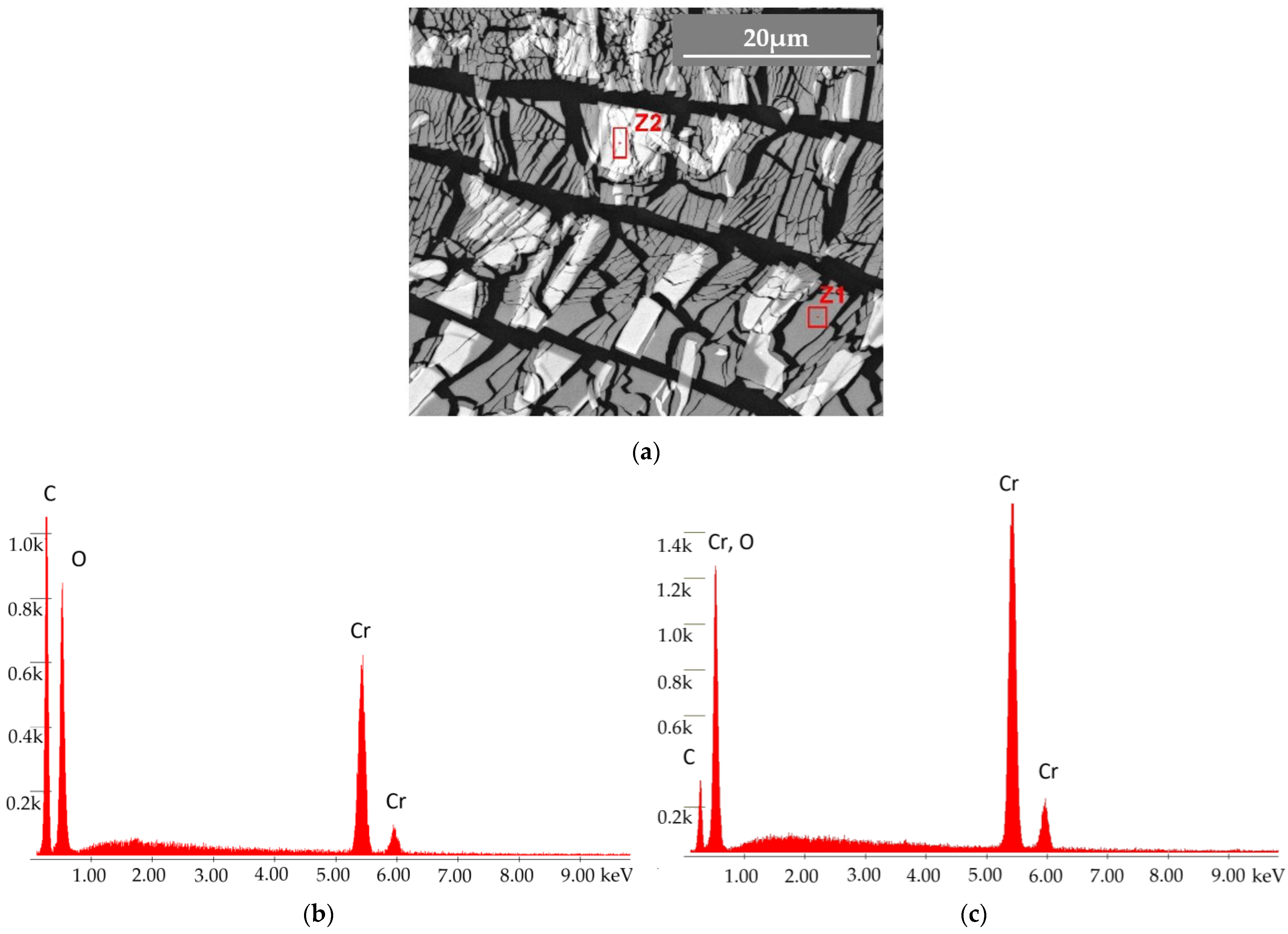
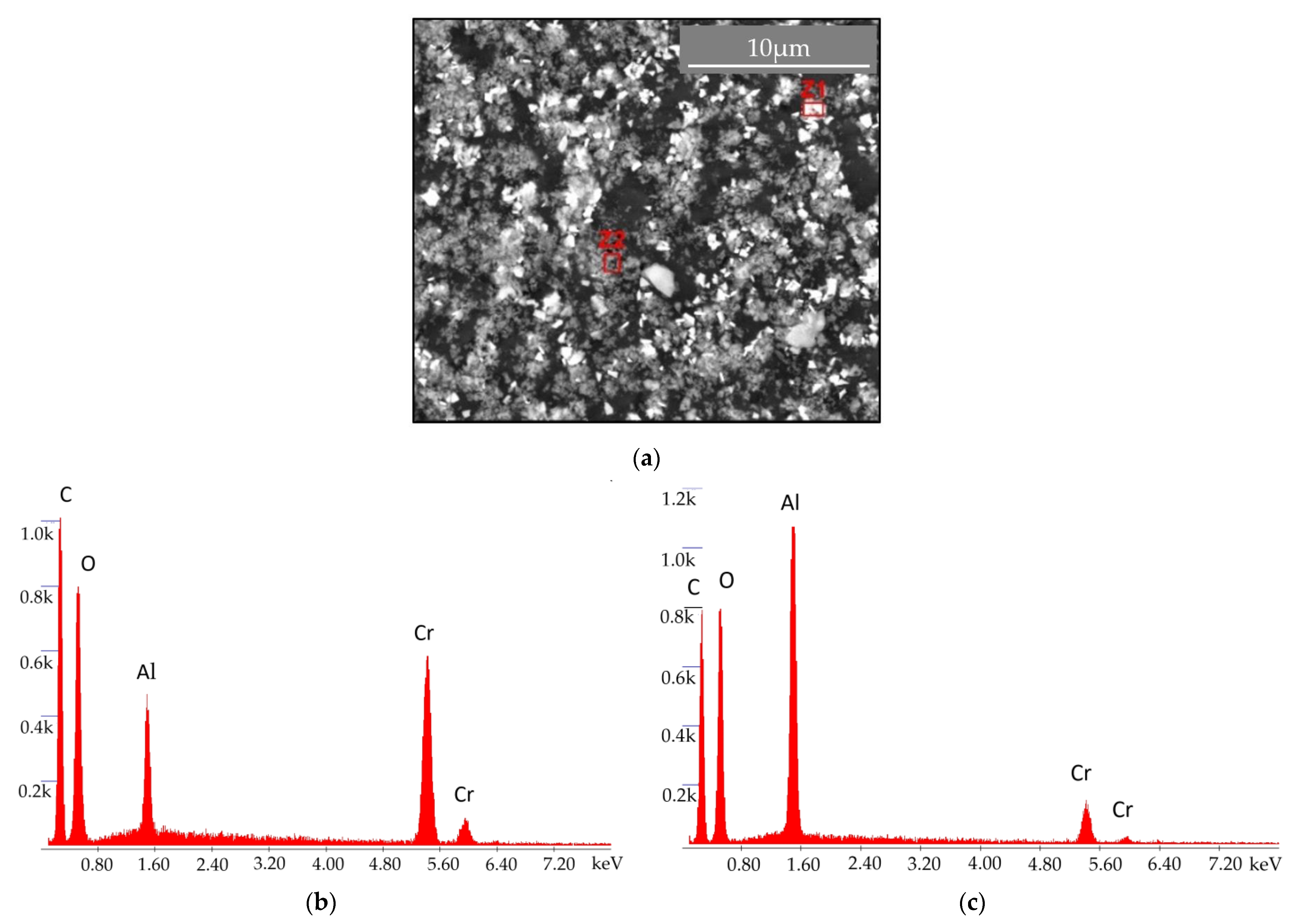
  • It was found that there were no contaminants present in the produced coatings, as the used target was composed of pure chromium;
  • Regarding the adhesion of the coating, no problems were registered. Indeed, the adhesion did not compromise the wear tests, because no delamination was detected in the craters’ surroundings;
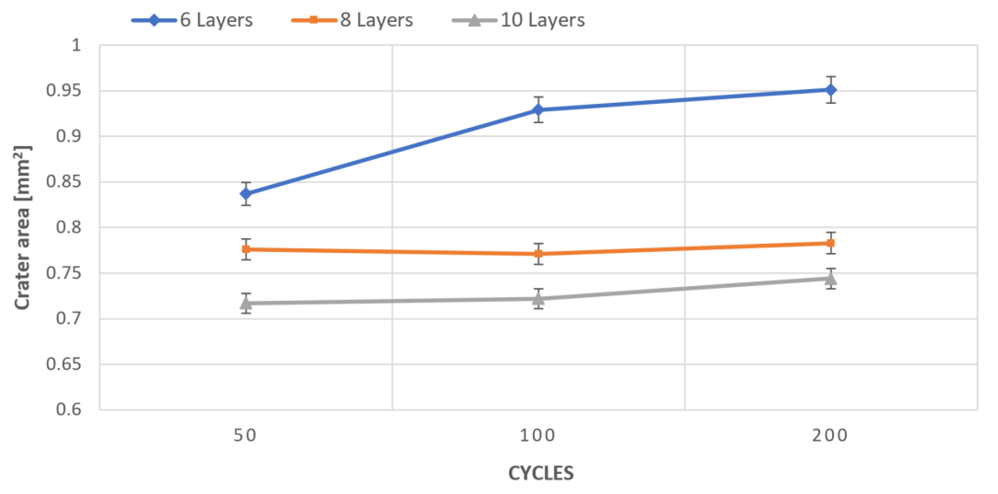
  • It was found that Cr coatings with 6 layers led to significant wear, unlike the coatings with 8 and 10 layers, where the wear is less severe;
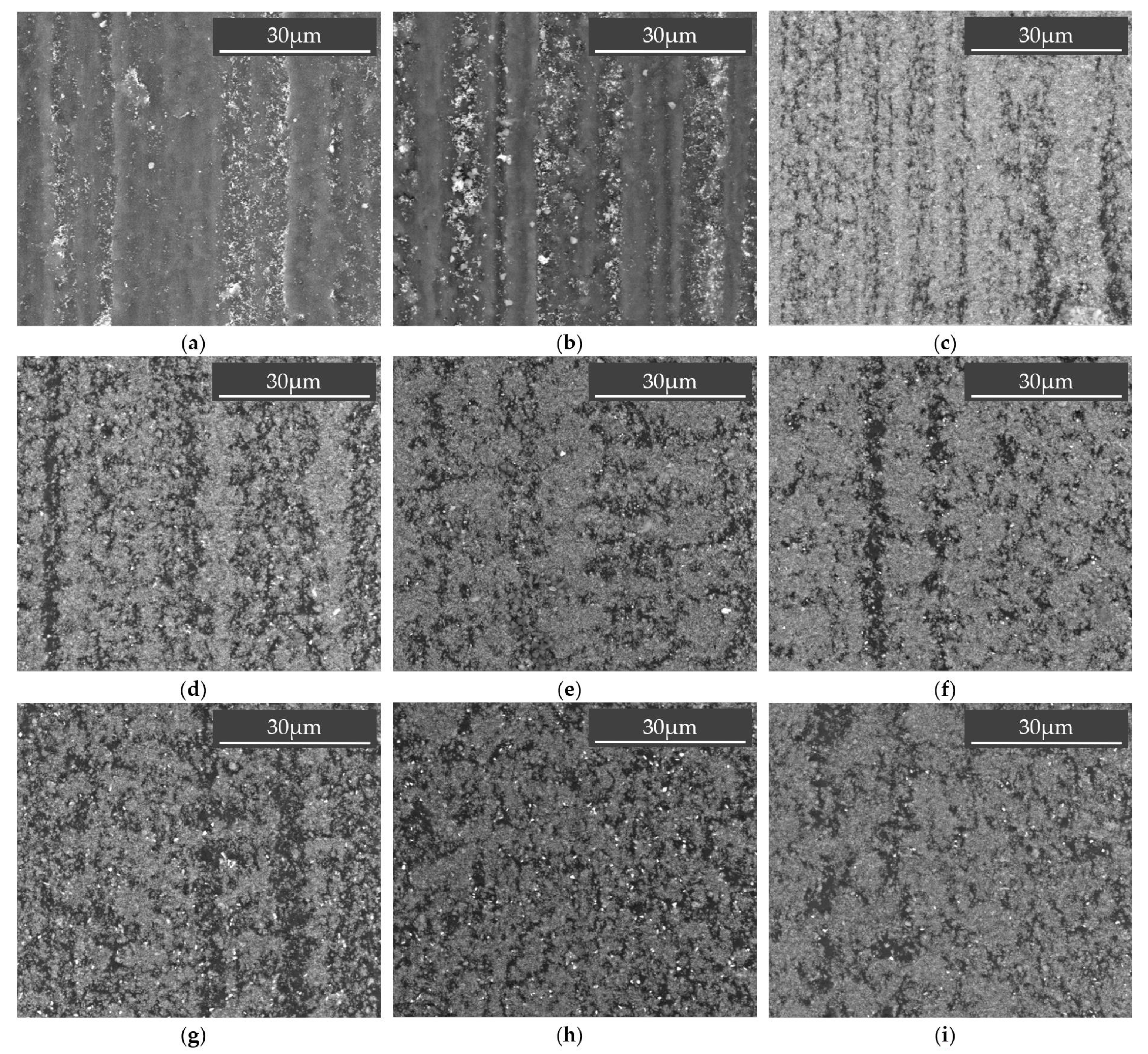
  • The normal load used is not perfectly suited for this kind of soft material, causing some coating and substrate deflection, which also caused the concentration of abrasive particles in the entrance and exit of the craters. This situation can be overcome by the use of other abrasive, slightly harder and with a higher granulometry;
  • The main wear mechanism observed on the craters was grooving, which changes to rolling as the number of cycles used in the micro-abrasion tests is increased. Moreover, there is an accumulation of alumina into the grooves promoted during the wear tests;
  • Despite the reported wear and taking into attention that the wear is important mainly for unexpected situations occurring during the assembly and repair of lightning automotive systems or backlit automotive components, the level of wear reported is adequate, showing good suitability of this coating for the intended purposes.
Thus, the outcomes of this work represent a real extension of the results and knowledge previously reported by other authors. Moreover, this configuration of wear test seems to be perfectly suitable to analyze the eventual wear induced in this kind of coating when applied to this type of material substrate, mainly in the case of lightning systems or backlit components for the automotive industry.

Author Contributions

A.B.: Investigation and writing original draft; G.P.: writing original draft; F.J.G.S.: Conceptualization, Supervision, Writing—review and editing; A.G.P.: Supervision and Writing—review and editing; A.A.F.: Investigation; V.F.C.S.: Investigation and Writing—review and editing. All authors have read and agreed to the published version of the manuscript.

Funding

This research received no external funding.

Institutional Review Board Statement

Not applicable.

Informed Consent Statement

Not applicable.

Data Availability Statement

No new data were created or analyzed in this study. Data sharing is not applicable to this article.

Acknowledgments

The authors would like to thank to Rui Rocha from CEMUP (Porto, Portugal), due to his active collaboration in getting the best SEM pictures, helping with his critical analysis of some phenomena. António Bastos is also acknowledged due to his support in Scratch-tests. Jorge Seabra is also acknowledged due to his support, as well as LAETA/INEGI/CETRIB due to the support providing free access to their labs to carry out wear tests.

Conflicts of Interest

The authors declare no conflict of interests regarding this paper.

References

  1. Silva, F.J.G.; Gouveia, R.M. Cleaner Production—Toward a Better Future, 1st ed.; Springer: Cham, Switzerland, 2020. [Google Scholar]
  2. Baptista, A.; Silva, F.; Porteiro, J.; Míguez, J.; Pinto, G. Sputtering Physical Vapour Deposition (PVD) coatings: A critical review on process improvement and market trend demands. Coatings 2018, 8, 402. [Google Scholar] [CrossRef] [Green Version]
  3. Baptista, A.; Silva, F.J.G.; Porteiro, J.; Míguez, J.L.; Pinto, G.; Fernandes, L. On the Physical Vapour Deposition (PVD): Evolution of magnetron sputtering processes for industrial applications. Procedia Manuf. 2018, 17, 746–757. [Google Scholar] [CrossRef]
  4. Zarka, M.; Dikici, B.; Niinomi, M.; Ezirmik, K.V.; Nakai, M.; Yilmazer, H. A systematic study of β-type Ti-based PVD coatings on magnesium for biomedical application. Vacuum 2021, 183, 109850. [Google Scholar] [CrossRef]
  5. Probst, J.; Gbureck, U.; Thull, R. Binary nitride and oxynitride PVD coatings on titanium for biomedical applications. Surf. Coat. Technol. 2001, 148, 226–233. [Google Scholar] [CrossRef]
  6. Geyao, L.; Yang, D.; Wanglin, C.; Chengyong, W. Development and application of physical vapor deposited coatings for medical devices: A review. Procedia CIRP 2020, 89, 250–262. [Google Scholar] [CrossRef]
  7. Pradhan, S.K.; Nouveau, C.; Vasin, A.; Djouadi, M.-A. Deposition of CrN coatings by PVD methods for mechanical application. Surf. Coat. Technol. 2005, 200, 141–145. [Google Scholar] [CrossRef]
  8. Bello, M.; Shanmugan, S. Achievements in mid and high-temperature selective absorber coatings by physical vapor deposition (PVD) for solar thermal application-A review. J. Alloys Compd. 2020, 893, 155510. [Google Scholar] [CrossRef]
  9. Selvakumar, N.; Barshilia, H.C. Review of physical vapor deposited (PVD) spectrally selective coatings for mid- and high-temperature solar thermal applications. Sol. Energy Mater. Sol. Cells 2012, 98, 1–23. [Google Scholar] [CrossRef]
  10. Duminica, F.-D.; Belchi, R.; Libralesso, L.; Mercier, D. Investigation of Cr(N)/DLC multilayer coatings elaborated by PVD for high wear resistance and low friction applications. Surf. Coat. Technol. 2018, 337, 396–403. [Google Scholar] [CrossRef]
  11. Bobzin, K.; Bagcivan, N.; Goebbels, N.; Yilmaz, K.; Hoehn, B.-R.; Michaelis, B.; Hochmann, M. Lubricated PVD CrAlN and WC/C coatings for automotive applications. Surf. Coat. Technol. 2009, 204, 1097–1101. [Google Scholar] [CrossRef]
  12. Guzman, L.; Wolf, G.K.; Davies, G.M. PVD–IBAD zinc coating development for automotive application. Surf. Coat. Technol. 2003, 174–175, 665–670. [Google Scholar] [CrossRef]
  13. Doleker, K.M.; Ozgurluk, Y.; Kahraman, Y.; Karaoglanli, A.C. Oxidation and hot corrosion resistance of HVOF/EB-PVD thermal barrier coating system. Surf. Coat. Technol. 2021, 409, 126862. [Google Scholar] [CrossRef]
  14. Shen, Z.; Liu, Z.; Um, R.; He, L.; Liu, G. Y–Er–ZrO2 thermal barrier coatings by EB-PVD: Thermal conductivity, thermal shock life and failure mechanism. Appl. Surf. Sci. Adv. 2021, 3, 100003. [Google Scholar] [CrossRef]
  15. Sousa, V.F.C.; Silva, F.J.G. Recent advances on coated milling tool technology—A comprehensive review. Coatings 2020, 10, 235. [Google Scholar] [CrossRef] [Green Version]
  16. Sousa, V.F.C.; Silva, F.J.G. Recent advances in turning processes using coated tools—A comprehensive review. Metals 2020, 10, 170. [Google Scholar] [CrossRef] [Green Version]
  17. Gouveia, R.M.; Silva, F.J.G.; Reis, P.; Baptista, A.P.M. Machining duplex stainless steel: Comparative study regarding end mill coated tools. Coatings 2016, 6, 51. [Google Scholar] [CrossRef] [Green Version]
  18. Sousa, V.F.C.; Silva, F.J.G.; Pinto, G.F.; Baptista, A.; Alexandre, R. Characteristics and wear mechanisms of TiAlN-based coatings for machining applications: A comprehensive review. Metals 2021, 11, 260. [Google Scholar] [CrossRef]
  19. Barrero, S.R.; Larrinoa, J.F.; Azkona, I.; Lacalle, L.N.L.; Polvorosa, R. Enhanced performance of nanostructured coatings for drilling by droplet elimination. Mater. Manuf. Process. 2016, 31, 593–602. [Google Scholar] [CrossRef]
  20. Bobzin, K.; Hopmann, C.H.; Gillner, A.; Brögelmann, T.; Kruppe, N.C.; Orth, M.; Steger, M.; Naderi, M. Enhanced replication ratio of injection molded plastic parts by using an innovative combination of laser-structuring and PVD coating. Surf. Coat. Technol. 2017, 332, 474–483. [Google Scholar] [CrossRef]
  21. Martinho, R.P.; Silva, F.J.G.; Alexandre, R.J.D.; Baptista, A.P.M. TiB2 Nanostructured coating for GFRP injection moulds. J. Nanosci. Nanotechnol. 2011, 11, 5374–5382. [Google Scholar] [CrossRef] [PubMed] [Green Version]
  22. Silva, F.; Martinho, R.; Andrade, M.; Baptista, A.; Alexandre, R. Improving the wear resistance of moulds for the injection of glass fibre—Reinforced plastics using PVD coatings: A comparative study. Coatings 2017, 7, 28. [Google Scholar] [CrossRef] [Green Version]
  23. Nunes, V.; Silva, F.J.G.; Andrade, M.F.; Alexandre, R.; Baptista, A.P.M. Increasing the lifespan of high-pressure die cast molds subjected to severe wear. Surf. Coat. Technol. 2017, 325, 319–331. [Google Scholar] [CrossRef]
  24. Vilaseca, M.; Pujante, J.; Ramírez, G.; Casellas, D. Investigation into adhesive wear of PVD coated and uncoated hot stamping production tools. Wear 2013, 308, 148–154. [Google Scholar] [CrossRef]
  25. Fernandes, L.; Silva, F.J.G.; Andrade, M.F.; Alexandre, R.; Baptista, A.P.M. Increasing the stamping tools lifespan by using Mo and B4C PVD coatings. Surf. Coat. Technol. 2017, 325, 107–119. [Google Scholar] [CrossRef]
  26. Fernandes, L.; Silva, F.J.G.; Alexandre, R. Study of TiAlN PVD coating on stamping dies used in tinplate food package production. Micromachines 2019, 10, 182. [Google Scholar] [CrossRef] [PubMed] [Green Version]
  27. Cora, O.M.; Ağcayazı, A.; Namiki, K.; Sofuoğlu, H.; Koç, M. Die wear in stamping of advanced high strength steels—Investigations on the effects of substrate material and hard-coatings. Tribol. Int. 2012, 52, 50–60. [Google Scholar] [CrossRef]
  28. Fessmann, J.; Mann, D.; Kampschulte, G.; Leyendecker, F.; Bolch, T.; Mertz, K.; Jonke, D.; Gamme, F.J.; Meyer, I.M.; Suchentrunk, R. Adherent metallization of carbon-fibre-reinforced plastic composites using a combined vacuum/electrochemical deposition process. Surf. Coat. Technol. 1992, 54–55, 599–603. [Google Scholar] [CrossRef]
  29. Fallah, P.; Rajagopalan, S.; McDonald, A.; Yue, S. Development of hybrid metallic coatings on carbon fiber-reinforced polymers (CFRPs) by cold spray deposition of copper-assisted copper electroplating process. Surf. Coat. Technol. 2020, 400, 126231. [Google Scholar] [CrossRef]
  30. Juarez, T.; Schroer, A.; Schwaiger, R.; Hodge, A.M. Evaluating sputter deposited metal coatings on 3D printed polymer micro-truss structures. Mater. Des. 2018, 140, 442–450. [Google Scholar] [CrossRef]
  31. Milde, F.; Goedicke, K.; Fahland, M. Adhesion behavior of PVD coatings on ECR plasma and ion beam treated polymer films. Thin Solid Film. 1996, 279, 169–173. [Google Scholar] [CrossRef]
  32. Qian, X.; Pang, X.; Gao, K.; Yang, H.; Jin, J.; Volinsky, A.A. Adhesion of sputtered nickel films on polycarbonate substrates. J. Mater. Eng. Perform. 2013, 23, 786–790. [Google Scholar] [CrossRef] [Green Version]
  33. Coto, B.; Hallander, P.; Mendizabal, L.; Pagano, F.; Kling, H.; Ortiz, R.; Barriga, J.; Selegård, L. Particle and rain erosion mechanisms on Ti/TiN multilayer PVD coatings for carbon fibre reinforced polymer substrates protection. Wear 2021, 466, 203575. [Google Scholar] [CrossRef]
  34. Vergason, G.; Fitch, M.; Smith, R.; Brazil, M.; Jochum, T. PVD chromium coatings replacing decorative chromium elec-troplated coatings on plastics. Soc. Vac. Coaters 2015, 403–410. [Google Scholar] [CrossRef]
  35. Zhang, D.; Zuo, X.; Wang, Z.; Li, H.; Chen, R.; Wang, A.; Ke, P. Comparative study on protective properties of CrN coatings on the ABS substrate by DCMS and HiPIMS techniques. Surf. Coat. Technol. 2020, 394, 125890. [Google Scholar] [CrossRef]
  36. Singh, M.M.; Vijaya, G.; Krupashankara, M.S.; Sridhara, B.K.; Shridhar, T.N. Studies on nanostructure aluminum thin film coatings deposited using dc magnetron sputtering process. Mater. Sci. Eng. 2016, 149, 012071. [Google Scholar] [CrossRef]
  37. Ferreira, A.A.; Silva, F.J.G.; Pinto, A.G.; Sousa, V.F.C. Characterization of thin chromium coatings produced by PVD sputtering for optical applications. Coatings 2021, 11, 215. [Google Scholar] [CrossRef]
  38. Fernandes, L.; Silva, F.J.G.; Paiva, O.C.; Baptista, A.; Pinto, G. Minimizing the adhesion effects in food packages forming by the use of advanced coatings. Procedia Manuf. 2018, 17, 886–894. [Google Scholar] [CrossRef]
  39. Teles, V.C.; de Mello, J.D.B.; da Silva Jr, W.M. Abrasive wear of multilayered/gradient CrAlSiN PVD coatings: Effect of interface roughness and of superficial flaws. Wear 2017, 376–377, 1691–1701. [Google Scholar] [CrossRef]
  40. Yao, S.H.; Su, Y.L.; Kao, W.H.; Cheng, K.W. Evaluation on wear behavior of Cr–Ag–N and Cr–W–N PVD nanocomposite coatings using two different types of tribometer. Surf. Coat. Technol. 2006, 201, 2520–2526. [Google Scholar] [CrossRef]
  41. Mishra, S.K.; Ghosh, S.; Aravindan, S. Investigations into friction and wear behavior of AlTiN and AlCrN coatings deposited on laser textured WC/Co using novel open tribometer tests. Surf. Coat. Technol. 2020, 387, 125513. [Google Scholar] [CrossRef]
  42. Bahi, R.; Nouveau, C.; Beliardouh, N.E.; Ramoul, C.E.; Meddah, S.; Ghelloudj, O. Surface performances of Ti-6Al-4V substrates coated PVD multilayered films in biological environments. Surf. Coat. Technol. 2020, 385, 125412. [Google Scholar] [CrossRef]
  43. Hoche, H.; Pusch, C.; Oechsne, M. Corrosion and wear protection of mild steel substrates by innovative PVD coatings. Surf. Coat. Technol. 2020, 391, 125659. [Google Scholar] [CrossRef]
  44. Kumar, P.K.; Kumar, A.S. Investigation of frictional characteristics of laser textured aluminium 6061 and aluminium 7071 alloys under dry sliding conformal contact in pin on disc tribometer. Mater. Today Proc. 2021, in press. [Google Scholar] [CrossRef]
  45. Eriksson, J.; Olsson, M. Tribological testing of commercial CrN, (Ti,Al)N and CrC/C PVD coatings—Evaluation of galling and wear characteristics against different high strength steels. Surf. Coat. Technol. 2011, 205, 4045–4051. [Google Scholar] [CrossRef]
  46. Andrade, M.F.C.; Martinho, R.P.; Silva, F.J.G.; Alexandre, R.J.D.; Baptista, A.P.M. Influence of the abrasive particles size in the micro-abrasion wear tests of TiAlSiN thin coatings. Wear 2009, 267, 12–18. [Google Scholar] [CrossRef] [Green Version]
  47. Pinto, G.; Baptista, A.; Silva, F.; Porteiro, J.; Míguez, J.; Alexandre, R. Study on the influence of the ball material on abrasive particles’ dynamics in ball-cratering thin coatings wear tests. Materials 2021, 14, 668. [Google Scholar] [CrossRef]
  48. Fildes, J.M.; Meyersa, S.J.; Kilaparti, R.; Schlepp, E. Improved ball crater micro-abrasion test based on a ball on three disk configuration. Wear 2012, 274–275, 414–422. [Google Scholar] [CrossRef]
  49. Silva, F.J.G.; Fernandes, A.J.S.; Costa, F.M.; Teixeira, V.; Baptista, A.P.M.; Pereira, E. Tribological behaviour of CVD diamond films on steel substrates. Wear 2003, 255, 846–853. [Google Scholar] [CrossRef]
  50. Baptista, A.; Silva, F.J.G.; Pinto, G.; Porteiro, J.; Míguez, J.; Alexandre, R.; Sousa, V.F.C. Influence of the ball surface texture in the dragging of abrasive particles on micro-abrasion wear tests. Wear 2021, 203730. [Google Scholar] [CrossRef]
  51. Ardila, M.A.N.; Costa, H.L.; de Mello, J.D.B. Influence of the ball material on friction and wear in microabrasion tests. Wear 2020, 450–451, 203–266. [Google Scholar] [CrossRef]
  52. Shipway, P.H.; Hogg, J.J. Wear of bulk ceramics in micro-scale abrasion—The role of abrasive shape and hardness and its relevance to testing of ceramic coatings. Wear 2007, 263, 887–895. [Google Scholar] [CrossRef]
  53. Cozza, R.C.; Tanaka, D.K.; Souza, R.M. Friction coefficient and wear mode transition in micro-scale abrasion tests. Tribol. Int. 2011, 44, 1878–1889. [Google Scholar] [CrossRef]
  54. Kusano, Y.; Van Acker, K.; Hutchings, I.M. Methods of data analysis for the micro-scale abrasion test on coated substrates. Surf. Coat. Technol. 2004, 183, 312–327. [Google Scholar] [CrossRef]
  55. Shipway, P.H. A mechanical model for particle motion in the micro-scale abrasion wear test. Wear 2004, 257, 984–991. [Google Scholar] [CrossRef]
  56. Silva, F.J.G.; Casais, R.B.; Martinho, R.P.; Baptista, A.P.M. Role of abrasive material on micro-abrasion wear tests. Wear 2011, 271, 2632–2639. [Google Scholar] [CrossRef] [Green Version]
  57. Silva, F.J.G.; Martinho, R.P.; Alexandre, R.J.D.; Baptista, A.P.M. Wear resistance of TiAlSiN thin coatings. J. Nanosci. Nanotechnol. 2012, 12, 9094–9101. [Google Scholar] [CrossRef] [PubMed]
  58. Silva, F.J.G.; Martinho, R.P.; Baptista, A.P.M. Characterization of laboratory and industrial CrN/CrCN/diamond-like carbon coatings. Thin Solid Film 2014, 550, 278–284. [Google Scholar] [CrossRef]
  59. SABIC Innovative Plastics Company, Lexan* Resin 143R. 2009. Available online: www.sabic.com/en/products/polymers/polycarbonate-pc/lexan-resin (accessed on 2 September 2020).
  60. ISO 4287. Geometric Product Specification (GPS). Surface Texture Profile Method: Terms, Definition and Surface Texture Parameters; ISO: Geneve, Switzerland, 1997. [Google Scholar]
  61. ISO 20502. Fine Ceramics (Advanced Ceramics, Advanced Technical Ceramics). Determination of Adhesion of Ceramic Coatings by Scratch Testing; ISO: Geneve, Switzerland, 2016. [Google Scholar]
  62. Sang-Hyuk, L.; In-Sun, P.; Bo-Hyun, S.; Jong Hyun, S.; Heehwan, C.; Jae-Hong, J.; Yong Uk, L.; Munpyo, H. Effect of sputtering parameters on the adhesion of copper/molybdenum metal on polymer substrate. Curr. Appl. Phys. 2001, 11, S12–S15. [Google Scholar] [CrossRef]
  63. Cozza, R. A study on friction coefficient and wear coefficient of coated systems submitted to micro-scale abrasion tests. Surf. Coat. Technol. 2013, 215, 224–233. [Google Scholar] [CrossRef] [Green Version]
  64. Sánchez-Huerta, D.; López-Perrusquia, N.; García, E.; Hilerio-Cruz, I.; Flores-Martínez MDoñu-Ruiz, M.A.; Muhl, S. Micro-abrasive wear behavior by the ball cratering technique on AISI L6 steel for agricultural application. Mater. Lett. 2021, 283, 1–5. [Google Scholar] [CrossRef]
  65. Gee, M.; Gant, A.; Hutchings, I.; Kusano, Y.; Schiffman, K.; Acker, K.; Poulat, S.; Gachon, Y.; Stebut, J.; Hatto, P.; et al. Results from an interlaboratory exercise to validate the micro-scale abrasion test. Wear 2005, 259, 27–35. [Google Scholar] [CrossRef]
  66. Cozza, R.; Mello, J.D.B.; Tanaka, D.K.; Souza, R.M. Relationship between test severity and wear mode transition in micro-abrasive wear tests. Wear 2007, 263, 111–116. [Google Scholar] [CrossRef]
  67. Martinho, R.P.; Andrade, M.F.C.; Silva, F.J.G.; Alexandre, R.J.D.; Baptista, A.P.M. Microabrasion wear behaviour of TiAlCrSiN nanostructured coatings. Wear 2009, 267, 1160–1165. [Google Scholar] [CrossRef] [Green Version]
Figure 1. Wear mechanism induced by the abrasive particles: (a) three-body abrasion (rolling); (b) mixed phenomenon; (c) two-body abrasion (grooving).
Coatings 11 00555 g001
Figure 2. Morphological characterization of 1 µm alumina powder abrasive.
Coatings 11 00555 g002
Figure 3. (a) TE66 Micro-scale abrasion tester tribometer and (b) schematic diagram of the ball-cratering tribometer.
Coatings 11 00555 g003
Figure 4. Sectional view showing the thickness of the films with: (a) 6 layers; (b) 8 layers, and (c) 10 layers.
Coatings 11 00555 g004
Figure 5. AFM images of the surfaces: (a) 6 layers, (b) 8 layers, and (c) 10 layers.
Coatings 11 00555 g005
Figure 6. SEM image details of scratch tests: (a) 6-layers, (c) 8-layers, (e) 10-layers, and (b) 6-layers, (d) 8-layers, (f) 10-layers with different magnifications (please see scale bars).
Coatings 11 00555 g006
Figure 7. EDS analysis of the scratch test (a) morphology of the scratch surroundings in a 6-layer coating; (b) spectrum detecting the presence of Cr (Z1), and (c) spectrum detecting the presence of Cr with a small peak of C (substrate) (Z2).
Coatings 11 00555 g007
Figure 8. Image’s sequence of the craters resulting from the micro-abrasion test obtained by SEM: 6 layers (a) 50 cycles; (b) 100 cycles; (c) 200 cycles; 8 layers; (d) 50 cycles; (e) 100 cycles; (f) 200 cycles; and, 10 layers; (g) 50 cycles; (h) 100 cycles; (i) 200 cycles.
Coatings 11 00555 g008
Figure 9. SEM and EDS analysis of a crater (a) SEM crater with 6-layer deposition film at 100 cycles; (b) Spectrum of Z1 zone where it is possible to identify the particles of Cr coating; (c) Spectrum of Z2 zone, showing a strong presence of alumina.
Coatings 11 00555 g009
Figure 10. Wear evolutions with different cycles for different layers.
Coatings 11 00555 g010
Figure 11. Crater worn surface morphology resulting from the micro abrasion test: 6 layers (a) 50 cycles; (b) 100 cycles; (c) 200 cycles, 8 layers; (d) 50 cycles; (e) 100 cycles; (f) 200 cycles, and 10 layers; (g) 50 cycles; (h) 100 cycles; (i) 200 cycles.
Coatings 11 00555 g011
Table 1. Processing conditions and properties of Polycarbonate, according to its technical sheet (Adapted from [59]).
PropertiesParameters
ProcessingMold temperature: 80–11 °C
Dehumidification time: 2–4 h
Dehumidification temperature: 120 °C
Melting temperature: 280–310 °C
Thermal PropertiesVicat temperature: 141 °C
Thermal expansion coefficient: 70 × 10−6/K−1
Rheological PropertiesMVR: 12 cm3/10 min
Optical PropertiesTransmittance: 88–90%
Refractive index: 1.586
Other PropertiesDensity: 1.2 g/cm3
Table 2. Chemical composition of Cr target (wt.%).
ElementCCaFeMoNNbNiOSVWCr
PPP (Parts Per Million)552870415461332455201047Balance
Table 3. Average values and standard deviations of the thin coatings thickness obtained by SEM.
Number of LayersThickness (nm)
6149.4 ± 0.011
8196.9 ± 0.015
10250.1 ± 0.017
Table 4. Mean values and standard deviations of the roughness obtained by AFM.
Number of LayersRa (nm)Rt (nm)Rq (nm)
64.2 ± 0.04365.1 ± 0.0215.6 ± 0.026
83.3 ± 0.03853.2 ± 0.0364.3 ± 0.038
101.9 ± 0.02720.1 ± 0.0192.5 ± 0.031
Table 5. Crater areas obtained for abrasion tests and standard deviations.
Number of LayersCrater Area for
50 Cycles (mm2)
Crater Area for
100 Cycles (mm2)
Crater Area for
200 Cycles (mm2)
6 Layers0.837 ± 0.0830.929 ± 0.0860.951 ± 0.088
8 Layers0.776 ± 0.0760.771 ± 0.0930.783 ± 0.102
10 Layers0.717 ± 0.0840.722 ± 0.0980.744 ± 0.092
Table 6. Volumes of lost material calculated after analyzing the craters and standard deviations.
Number of LayersVolume of Material Removed (μm3)
50 Cycles100 Cycles200 Cycles
6 Layers0.179 ± 0.0060.190 ± 0.0090.201 ± 0.008
8 Layers0.146 ± 0.0070.148 ± 0.0060.157 ± 0.005
10 Layers0.137 ± 0.0040.138 ± 0.0050.141 ± 0.007
Publisher’s Note: MDPI stays neutral with regard to jurisdictional claims in published maps and institutional affiliations.

