1. Introduction
Friction Stir Welding (FSW) is a joining method where a rotating tool is traversed along the interface of two work pieces, mechanically intermixing them without causing melting. The combination of frictional heat and severe plastic deformation leaves a high quality fine-grained joint, leading to excellent joint properties, achieved with relatively low energy consumption and low distortion. The joints are porosity-free, have high mechanical strength and thus are impermeable to gases and fluids. Recently a variant of FSW designated as Stationary Shoulder Friction Stir Welding (SS-FSW) has been developed which further improves the mechanical properties and surface finish of the joint [
1]. Despite a superior quality of the end-product, industrial adoption of FSW and SS-FSW for high melting point materials, such as steel and titanium, is restricted primarily by severely limited tool life due to the extreme environments to which tools are exposed. For lower melting point materials, such as aluminium, SS-FSW technology currently has difficulties with material sticking to the stationary shoulder producing a weld with a rough surface finish, especially at high welding speeds [
2]. FSW tools require protection from high temperature, severe abrasion and the corroding influence of the freshly exposed, highly reactive surfaces of the metals being joined. Although these conditions are not too different from those experienced by cutting tools, FSW has some additional demands; the whole of the “tool probe” is in contact with the material(s) being welded, often for many minutes, and, because of the nature of the FSW process there is no way of applying an effective cooling and/or lubrication regime, hence the thermal and material environment to which FSW tooling is exposed is substantially more demanding. In welding aluminium alloys for example, the shoulder experiences oxidising environments and temperatures in excess of 350 °C whereas the conditions at the rotating probe resemble those at a temperature of 550 °C in vacuum with an added aggressive metallurgical reaction with the semi-molten aluminium [
3]. Peak temperatures up to 605 °C have been reported for conventional FSW [
4]. Furthermore, the probe rotates at a high rotational speed (typically 2000 to 4000 rpm) within the stationary shoulder, with less than 0.2 mm clearance between the probe and the bore. This makes the probe-shoulder interface particularly prone to wear, especially for welding alloys with abrasive particles such as high pressure die casting (HPDC) aluminium alloys which typically contain 10% silicon.
The simultaneous requirements for toughness and chemical inertness of the probe and shoulder are typically met by combining a steel body to address the former and a coating to address the latter. Unlike traditional welding processes, FSW does not use shielding gases or fluxes. The heat generated by the rotating tool due to the friction forces and plastic deformation (pushing action of the traversing tool shoulder) is utilised to join the pieces together. Thus, the choice of a coating for the FSW tool depends on the fact that it should have a moderately high friction coefficient, a high wear resistance and that it can be utilised for both the shoulder and the probe. Also, in order to achieve a smooth surface finish, chemical compatibility between the coating and the weld material should be a minimum to avoid any build-up of material on the shoulder. In the case of SS-FSW tooling, because the requirements of probe and shoulder are somewhat different, it would be feasible to use different, optimised, coating materials on the probe and shoulder.
The coating technology considered most appropriate for developing solutions to the issues highlighted is Physical Vapour Deposition (PVD). PVD has been used since the early 1980′s to reduce wear and increase the productivity of cutting and forming tools through the deposition of binary compounds, such as titanium and chromium nitrides, and, more recently, ternary materials such as aluminium titanium and titanium silicon nitrides, which provide protection under more demanding operating conditions where the simple binary coatings fail rapidly [
5].
In order to prolong the life of SS-FSW tooling, potential coatings must be characterized by high adhesion, appropriate friction coefficient, low roughness, high wear and oxidation resistance, and low affinity to the work piece material both at high temperature and under vacuum. There are few materials and technologies that can offer all the advantages. Whilst the interaction of the coating with the workpiece material is poorly understood, it is crucial for the improvement of SS-FSW process.
This work compares the performance of a range of coatings and coating technologies in SS-FSW of aluminium AA6082-T6 alloy. Firstly, two PVD technologies were evaluated; arc evaporation and HIPIMS (High Power Impulse Magnetron Sputtering), both of which are characterized by high ionization and deposition energy of the coating flux [
6,
7]. Arc evaporation is a well-established technology used for commercial coating of a wide variety of tools and components since the early 1980′s [
7,
8], which in this study was used to deposit AlTiN—a hard abrasion- and oxidation- resistant coating material. HIPIMS is a recently developed variant of magnetron sputtering, providing significantly enhanced compositional, structural and morphological control of the deposited film [
9,
10,
11], as well as very high levels of coating adhesion [
12]. HIPIMS was used to produce TiAlN/VN nanoscale multilayer coating with high hardness and lubricious wear surface which prevents material build-up [
13]. An alternative, though related technology, Chemical Vapour Deposition (CVD), which provides coatings of the same general type as PVD but deposited at temperatures of ≥800 °C [
14] was also evaluated for the deposition of TiB
2 and TiBCN coating materials which have high hardness and which are not currently available by PVD. Finally, a third coating variant, Plasma Assisted Chemical Vapour Deposition (PACVD), which combines aspects of both PVD and CVD [
15], was also used for the preparation of amorphous diamond-like carbon coatings (a-C:H) henceforth referred as DLC, which display a very low affinity for aluminium and have very low coefficients of friction [
16]. Detailed characterization of these coating variants and their performance in the extreme operating conditions of SS-FSW are presented below.
2. Experimental
2.1. Coating Deposition
For this study, five different coatings were evaluated: nanoscale multilayer TiAlN/VN, deposited by HIPIMS; AlTiN deposited by arc evaporation; DLC deposited by PACVD; and TiB2 and TiBCN deposited by CVD. These were selected based on their excellent wear resistance and anticipated low affinity for aluminium. Coatings were deposited onto flat mirror-polished high speed steel (M2) coupons to facilitate coating characterization and onto FSW probes and shoulders manufactured from hot work tool steel (H13) for use in welding trials.
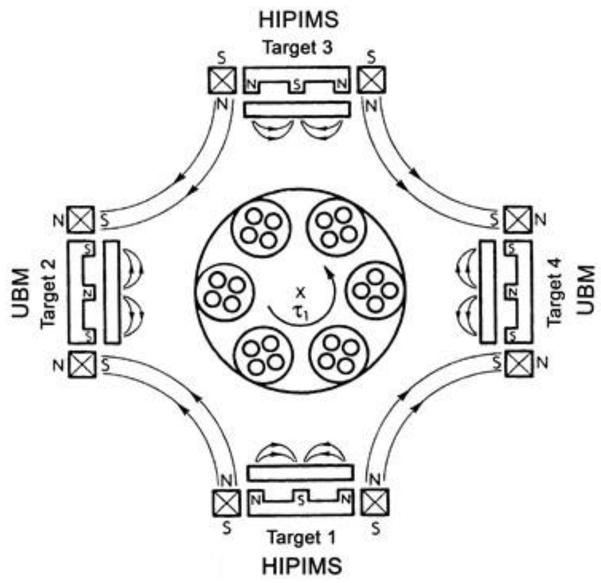
The nanoscale multilayer TiAlN/VN coatings were deposited in an industrial sized coating deposition equipment- HTC 1000-4, Hauzer Techno Coatings, Europe B.V., Venlo, The Netherlands, enabled with HIPIMS technology, based at the National HIPIMS Technology Centre in Sheffield Hallam University, Sheffield, UK.
Figure 1 shows a schematic cross section of this coating chamber. It consists of a centrally placed substrate holder surrounded by 4 evenly spaced planar magnetron sputtering plasma sources which can operate rectangular sputtering targets 600 mm × 200 mm in size. These sources can be operated in an unbalanced dc magnetron (UBM) sputtering or HIPIMS mode allowing to set different sputtering combinations as required. The system is also equipped with a dedicated bias power supply (Hüttinger Elektronik Sp. z o.o., Warsaw, Poland), which maintains a constant dc voltage during HIPIMS pulses [
17].
In this study, TiAlN/VN nanoscale multilayer coatings were deposited by sputtering in an Ar + N
2 (flow ratio of 1:1) atmosphere (total working pressure of 10
−3 mbar) while operating a set of TiAl and V targets each in HIPIMS mode and a second set in DC sputtering mode. Targets were sputtered with an average power of 8 kW irrespective of the technique. In the case of HIPIMS, rectangular voltage pulses with a duration of 200 µs, frequency of 100 Hz and duty cycle of 1% were employed. The temperature of deposition was 400 °C with a substrate bias voltage of Ub = −65 V. Before the actual coating synthesis, all the samples were subjected to an adhesion-improving HIPIMS etching pre-treatment [
12,
18], wherein the samples were sputter-cleaned and implanted with V
+ ions extracted from a HIPIMS discharge sustained on a V target.
Single-layer AlTiN coatings were deposited by random-arc reactive evaporation from alloy targets in an eight-evaporator Multi-Arc coating system at Ionbond, Ionbond UK Ltd, Consett, UK using commercially established and widely proven coating deposition conditions.
The DLC coatings were produced at Ionbond, UK Ltd, Consett, UK using a proprietary process in an Ionbond PACVD coating system using an underlayer of sputter deposited CrN. Finally, the TiB2 and TiBCN coatings were at IHI Ionbond AG’s coating centre, (now IHI Bernex, Olten, Switzerland) using proprietary CVD processes.
All parts were tested in the as-coated condition except those coated by CVD, which, because of the high deposition temperatures used, were re-heat treated under vacuum to recover the original substrate hardness and metallurgical properties.
2.2. Coating Characterisation and Tribological Studies
All the coatings were thoroughly characterised using a number of analytical techniques. The microstructural features and morphology of the coatings and sliding wear tracks were investigated with a Scanning Electron Microscope (SEM) (FEI NOVA-NANOSEM 200, (Eindhoven, The Netherlands). A Phillips CM20 (Eindhoven, The Netherlands) transmission electron microscope (TEM) was operated in bright field imaging mode to obtain cross-sectional images of the TiAlN/VN coating. The texture of the coatings was investigated by XRD, using glancing angle (2° incidence) and Bragg-Brentano (2θ, 20–100° (step size = 0.026 (°2θ), step time = 198.64 s)) geometries. The bi-layer period of the multilayer TiAlN/VN coating was investigated by the low-angle (2θ, 1–10° (step size = 0.03 (°2θ) and time of 148.92 s)) Bragg-Brentano geometry XRD technique.
The friction coefficient values and dry sliding wear coefficients (K
C) of the coatings were studied using a high-temperature CSM-Anton Paar pin-on-disk apparatus adhering to the general principles of ASTM G99-17 standard [
19]. In these tests, coated M2 High Speed Steel (HSS) samples were slid against a static partner at a linear speed of 0.1 ms
−1 under a static normal load of 5 N. To approximate the conditions of the FSW process, tests were carried out at room temperature (25 °C) and at temperatures of 350 and 550 °C, the second of which corresponded to the peak temperatures at the shoulder, the latter to that of the probe. The environment of the probe, where it is immersed into the workpiece material without contact to oxygen was further simulated in dry sliding wear tests in vacuum at ambient temperature (approximately 22 °C), 350 and 550 °C which were conducted using a high-temperature vacuum tribometer from CSM-Anton Paar [Peuseux, Switzerland]. Since several tests were planned at high temperature, both in air and vacuum, these test parameters demanded a counterpart which would behave consistently in all the conditions without adding complexity to the already intricate tribological phenomenon. Hence, for these tests, a compositionally inert Al
2O
3 ball (6 mm diameter) was chosen as the static partner. The sliding distance in these tests depended on the performance of each coating, i.e., the total sliding distance was set to restrict the resulting volume loss to within the coating thickness in order to calculate the dry sliding wear coefficient (K
C). A Horiba-Jobin-Yvon Raman spectrometer (LabRam HR800, Palaiseau, France) fitted with a green laser (wavelength λ = 532 nm, 5 mW output power) was used to analyse the oxidation products formed in the wear tracks. The spectra were collected by averaging over 3 acquisitions in the wavelength range of 100–2000 cm
−1. Lab-Spec software (version V5 embedded into the spectrometer system) was used to correct for the background, de-spike and smooth the data and a multi-peak Gaussian-fitting function was used to de-convolute the spectra and identify the Raman peaks.
A Dektak 150 (Veeco Instruments, New York, NY, USA) stylus profilometer was used to measure surface roughness and calculate volume loss after the pin-on-disk tests. A CSM-Anton Paar nano-hardness (Peuseux, Switzerland) tester was used to determine the nano-hardness of the coatings where the maximum load applied was 10 mN. Coating adhesion was measured by Rockwell C intentation (ISO 26,443 standard) adhesion tests as well as progressive loading scratch tests (ISO 20502) conducted on CSEM-Anton Paar REVETEST (Peuseux, Switzerland). The normal load was progressively increased from 5 to 100 N at the rate of 0.01 Nm−1 (10 N/mm) with an indenter moving at a velocity of 1.6 × 10⁻⁴ ms−1 (10 mm/min). The critical load of coating adhesion failure (Lc2 value) was identified with the help of an attached optical microscope along with the corresponding rise in the acoustic emissions displayed by the instrument.
2.3. FSW Experiments
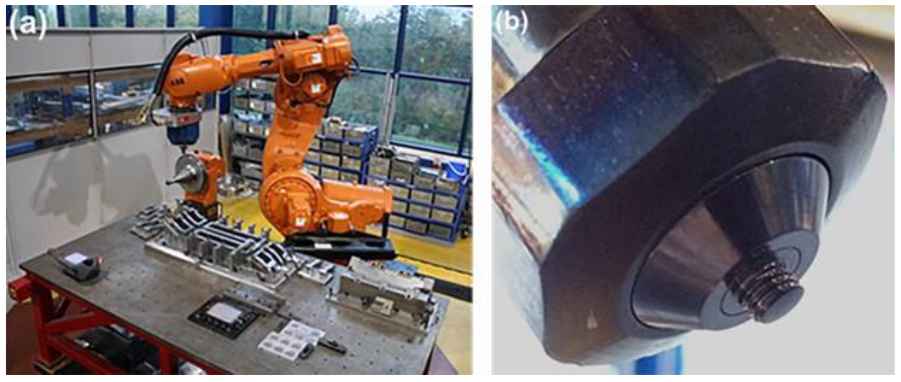
Welding trials were carried out at the TWI Technology Centre, Yorkshire, UK on the FlexiFab FSW robot system shown in
Figure 2.
In the tests the coated tools were employed to friction stir weld a 6 mm thick aluminium alloy (AA6082-T6) plate with a weld penetration depth of 3 mm. A cylindrical threaded probe with a nominal diameter of 5 mm. The probe shank diameter was 8 mm with g6 tolerance. The shoulder had an inner diameter between 8.1 and 8.15 mm. Note that due to the different thicknesses of the coatings subsequently applied, the probe-shoulder clearance varied for different coatings.
The tool was plunged in force control mode, whereby a constant force of 5 kN was applied to the tool while the probe was rotating at 2800 rpm. Once plunging was completed, i.e., the shoulder was in firm contact with the material to be welded at the desired peak temperature of 600 °C, the traverse motion was initiated over a weld distance of 0.1 m at a speed of 0.01 m·s
−1 with a constant load of 7 kN. The exact load distribution between probe and shoulder could not be assessed but it is estimated that 60% to 90% of the force applied to the workpiece material is borne by the shoulder. The rotation speed of the probe was maintained at 2800 rpm. In order to obtain a fully consolidated weld with a good surface appearance, the tool was tilted to an angle of 1.5° towards its trailing edge. The finish of the weld was qualitatively analysed and deemed acceptable if it had no more than minor surface breaking voids with a general appearance similar to the weld shown in
Figure 3. All the coated tools and shoulders were subjected to weld trials with similar parameters and conditions.
3. Results and Discussion
3.1. Coating Microstructure, Morphology and Crystallographic Texture
Figure 4a–e shows SEM images (secondary electron imaging mode) of the coating surface revealing their morphology in detail. The arc-deposited monolithic AlTiN coating (
Figure 4a) had the densest microstructure consisting of closely packed nano-sized columnar grains which are punctuated by micron-size droplet defects and voids. The arc deposition process is well known for producing highly ionised plasmas and thus the extreme densification and the nano size of the grains can be attributed to the intense bombardment of the depositing flux during the coating growth stage [
19]. Despite being dense, the coating had a high roughness (Ra = 0.164 µm) which could be a result of deposition of micron-size macro-droplets of the depositing material [
20] and craters associated with their expulsion post-deposition.
The PECVD-synthesised DLC coatings (
Figure 4b) and HIPIMS-deposited nanoscale multilayer TiAlN/VN coatings (
Figure 4c) consisted of pronounced globular grains. In the case of DLC coatings, the grains appeared coarser in size with well-defined inter-columnar boundaries. The finer columnar grains in the TiAlN/VN coating appeared to be densely packed with narrow, in some cases indistinguishable, intercolumnar boundaries. The absence of large-scale defects in the DLC and TiAlN/VN coatings rendered a smooth surface with roughness values (Ra) of 0.04 and 0.06 µm respectively. The CVD-grown TiBCN coating microstructure (
Figure 4d) consisted of macroscopic grains (around 8–12 µm in size) formed due to the clustering of smaller grains. Though very densely packed, the conglomerated macroscopic grains had deep grain boundaries that ultimately resulted in the surface texture being non-uniform and rough with Ra = 0.63 µm. Of all the coatings analysed in this study, the TiB
2 coating,
Figure 4e, had the most under-dense microstructure. It consisted of clusters of randomly oriented irregular shaped nanosize grains (around 200–300 nm) to form globular grains of around 1 to 3 micrometers in diameter. Even though these globular grains appeared widely spaced with huge gaps in between them, their orderly stacking rendered them smoother (Ra = 0.20 µm) as compared to TiBCN coatings.
Figure 5 shows a bright field cross-sectional TEM (CTEM) image of the HIPIMS deposited TiAlN/VN coating consisting of a TiAlN base layer followed by an uninterrupted deposition of alternating TiAlN and VN nanolayers. The TiAlN base layer was found to be very dense and free of defects (macroparticles). The transition from the base layer to the multilayer structure was found to be seamless with several columnar grains showing evidence of epitaxy extending from the bottom of the base layer into the column as growth progressed. These individual densely packed columnar grains consisted of alternating nanoscale TiAlN (bright contrast) and VN (dark contrast) sublayers stacked in an orderly fashion. The nanoscale layers were found to be very flat, well defined and with sharp interfaces. XRD results indicated the bi-layer thickness to be in the range of 4.7 nm. These engineered interfaces generated by modulation of the layered structure act as planes for energy deflection, stress relaxation or crack deflection and hence impart high toughness to the coating [
21] and an unique layer by layer wear debris generation when subjected to harsh wear conditions [
22]. As a result, the coating inherits high hardness, high toughness and a high wear resistance.
Table 1 summarises the characterisation results of all the coatings. The CVD-deposited TiBCN coating was the thickest of all with a thickness value of 8.5 microns whereas the arc deposited AlTiN coating was the thinnest around 1.5 micrometers. All the coatings exhibited good adhesion as the L
c2 values were in the range of 52–58 N and the Rockwell indentations resembled Class 1 classification. Barring the DLC coating (hardness around 11 GPa) all other coatings could be categorised as hard coatings with their hardness values in the range of 28–35 GPa. Owing to the under-dense microstructure, the nanohardness of TiB
2 coating could not be reliably determined. XRD analyses revealed the AlTiN and TiAlN/VN to have a F.C.C. NaCl type crystal structure with a preferred (200) orientation characteristic of highly ionised deposition processes. In the case of TiB
2 coating, the crystals had a H.C.P structure with a preferred (001) orientation.
The coatings were thoroughly investigated to find the right combination of friction coefficient and wear resistance for the FSW application. Pin on disk experiments were conducted at room temperature, 350 and 550 °C using an Al2O3 ball as counterpart.
3.2. Room Temperature Sliding Wear Tests
Figure 6a–e shows the friction coefficient values recorded for each coating under dry sliding wear conditions at room temperature (approximately 22 °C). Results showed that the DLC coatings had the lowest friction coefficient with a mean friction coefficient value of µ = 0.039. Even though it had the lowest hardness value of 11 GPa, it showed the highest wear resistance (K
C = 2.46 × 10
−16 m
3·N
−1·m
−1). The wear track appeared smooth with shallow grooving resulting from a 3 body contact abrasion mechanism. In comparison, other monolithic coatings such as the AlTiN, TiBCN and TiB
2 showed a trend of increasing friction coefficient values with increasing number of laps. The friction curve for AlTiN became noiser as the number of laps increased which indicated that as the test progressed coarser wear debris was generated and led to a 3 body contact abrasion mechanism. It is well known that under sliding wear conditions, the columnar grain tops of monolithic PVD coatings can break and generate wear debris which can be around 50–75 nm in size [
22]. SEM images (not included) confirmed the presence of coarser wear debris in the wear track. Consequently, the AlTiN coating displayed a high wear rate (K
C = 8.42 × 10
−14 m
3·N
−1·m
−1) despite being very hard in nature.
In contrast, the friction curve for nanoscale multilayer TiAlN/VN coating had a smooth appearance in the steady state conditions and attained a mean value of µ = 0.70. SEM images (not included) showed shallow grooving and evidence of oxide formation in the wear track due to tribo-oxidation wear mechanism [
23]. In areas where the oxide layers were removed due to the sliding action of the counterpart, dome shaped columnar tops of the coating were visible which indicated that the coating was not perforated. Literature suggests that due to the high temperatures at asperity contacts (temperatures can reach around 800 °C when sliding in dry conditions), the elements Ti and V form lubricious Magneli phase structured oxides [
24,
25]. Previous work of sliding wear studies on TiAlN/VN suggested the presence of a tribofilm on the surface of the coating. This 20–50 nm thick film, which is formed due to dense packing of wear debris, plastically deformed nanolayers from the top of the coating and oxides is strongly adherent to the surface of the coating and confines the resulting wear debris to particles which are 8–10 nm in size [
26]. Thus, the stable friction characteristic of TiAlN/VN coating was the result of a combination of factors: lubricious oxides, presence of a tribofim and the unique nanosize layer by layer removal wear mechanism of the HIPIMS deposited hard layers of TiAlN and VN. Consequently, the TiAlN/VN coating exhibited a high wear resistance (of K
C = 5.94 × 10
−16 m
3·N
−1·m
−1) which was comparable to that of DLC coatings. In the case of AlTiN coating, any lubricious effect of Ti-based oxides appeared to be completely outweighed by the breaking of the columnar grains leading to a high wear rate of the coating.
The TiBCN and TiB2 coatings show high friction coeficient values and high wear rates (KC in the range of 4 × 10⁻¹⁵ m3·N−1·m−1) along with the high wear of the Al2O3 ball counterpart. For both the coatings, the wear mechanism consisted of plastic deformation of the globular grains followed by their cracking and shearing. This led to the generation of coarser (macrosized) wear debris and consequently to higher friction coefficent values and higher wear rates. In most of the room temperature tests, the static Al2O3 counterpart exhibited negligible wear (not quantifyable). However, in the case of tests against TiBCN coatings, the Al2O3 ball exhibited a high wear rate of KC = 2.4 × 10⁻¹⁵ m3·N−1·m−1.
3.3. Sliding Wear Tests at Temperature of 350 °C
Figure 7a–e shows the friction curves recorded for each coating when tested at 350 °C. As anticipated, in comparison to the room temperature tests, barring DLC, all the coatings showed a slight increase in the steady state friction coefficient values due to the loss of condensed water vapour film lubrication usually present at room temperatures. The nature of the curves for all the coatings resembled that at room temperature.
However, the rise in test temperature also led to a decrease in the wear resistance offered by some of the coatings. As at room temperature, TiAlN/VN and DLC showed better wear resistance at this test temperature (
Table 2) as compared to AlTiN, TiBCN and TiB
2 coatings. The beneficial effect of the formation of lubricious oxides and the superior nanolayered structure of the TiAlN/VN coating was also evident at this temperature. The friction curve appeared very smooth (
Figure 7c) with a mean value µ = 0.88 until the coating was perforated at around 4000 laps. Even though the DLC coating showed a very low friction coefficient value, which further reduced during the test, visual inspection and Raman spectroscopy results (not shown) indicated the beginning of graphitisation of the coatings which probably contributed to the reduced friction coefficient but also led to a decrease in the wear resistance offered by the coating. However, unlike the other coatings the DLC appeared to remain intact and survive to the end of the test at 10,000 laps. The TiBCN coating exhibited a high friction coefficient value of 0.94. Due to the uneven wear of the coating columnar tops, profiling of the TiBCN wear track and thus calculation of the dry sliding wear coefficient (K
C) was not possible. Similar to the room temperature performance it was estimated to be in the same range as that of the TiB
2 coating. Even though the TiB
2 coating had a lower friction coefficient value it had a lower wear resistance as comared to the TiAlN/VN. Thus, with a combination of attributes of moderate and near steady friction behaviour, structural integrity and wear resistance, the multilayer TiAlN/VN coating fared better than those analysed in this study in these test conditions. Similar to the results of the room temperature tests, noticiable wear of the Al
2O
3 counterpart was only observed in the case of TiBCN coatings (K
C = 7.37 × 10
−14 m
3·N
−1·m
−1). For all other tests at 350 °C, the static exhibited negligible wear.
3.4. Sliding Wear Tests at Temperature of 550 °C
Figure 8a–e shows the friction curves recorded against the number of laps for the coatings tested at 550 °C in air. The total sliding distance (number of laps) for a particular test on a coating was set in order to restrict the wear track and thereby volume loss to the coating without through-thickness perforation.
Figure 8a shows the friction curve recorded for the AlTiN coating. After an initial rise from 0.65 to ~0.85 the friction coefficient appeared to oscillate between µ = 0.7 and 0.8, with a general downward trend to a final value of 0.7. The wear track showed accumulation of coating debris at regular intervals (
Figure 9a) and consisted of grooves formed due to 3-body contact abrasion resulting from trapped wear debris between the counter body and the coating (
Figure 9b). EDX, Raman spectroscopy (not shown) and SEM studies confirmed the presence of lubricious Ti-, V- and Al- based oxides along with oxides of Fe (substrate) in the wear track (
Figure 9b). This mix of oxides and its periodic fragmentation resulted in the unstable behaviour of the friction in the later stages of the test, amid a slight drop in the friction coefficient value. As the wear mechanism showed similarities to that at room temperature and 350 °C, the resulting sliding wear coefficient was also in a similar range of K
C = 5.14 × 10
−14 m
3·N
−1·m
−1.
Amongst all the coatings analysed, the performance of DLC coating,
Figure 8b, deteriorated the most when the test temperature was increased. The friction coefficient value showed a steep increase from 0.02 at 350 °C to 0.72 at 550 °C. SEM images,
Figure 9c,d, EDX analysis and Raman spectroscopy results (not shown) confirmed that at this temperature the coating underwent rapid decomposition (graphitisation). The wear track mainly consisted of oxidised substrate (within 400 laps) with no trace of any intact coating. Consequently, the dry sliding wear coefficient showed an increase of two orders of magnitude as compared to the room temperature, though interestingly it was still only half that of the AlTiN film (
Table 2).
The TiBCN and TiB
2 coatings (
Figure 9e–f and
Figure 9g–h respectively) showed almost no formation of oxides or build-up of wear debris. In the case of TiBCN coating the friction coefficient reached µ = 1 (around 1500 laps) followed by a gradual drop to stabilise at around µ = 0.5 until the end of the test. The wear mechanism mainly consisted of wear of the columnar tops of the coating (
Figure 4d) which generated finer wear debris (
Figure 9f). Even though noticeable wear of the Al
2O
3 counterpart (K
C = 9.3 × 10
−16 m
3·N
−1·m
−1) was observed, it was comparatively less than observed for tests at room temperature and 350 °C and could be attributed to the finer debris generated. The coatings exhibited a dry sliding wear coefficient of K
C = 5.08 × 10
−14 m
3·N
−1·m
−1. Similarly, the wear track of the TiB
2 coatings (
Figure 9g–h) consisted of worn and flattened globular grains (
Figure 4e). The friction coefficient showed a steady increase in value with the increase in number of laps to reach a value of µ = 0.84 at the end of the test (
Figure 8e). The coatings exhibited a dry sliding wear coefficient of K
C = 2.08 × 10
−14 m
3·N
−1·m
−1.
As the friction curve in
Figure 8c indicates, the nanoscale multilayer TiAlN/VN coating displayed the lowest variation in friction coefficient, with the friction stabilising to a steady value of around µ = 0.77 at the end of the test at 4000 laps. SEM images (
Figure 10a,b), EDX results and Raman spectroscopy results indicated that the wear track had not perforated the coating and showed build-up of oxides all over the track. Unlike results at room temperature, high temperature of 550 °C favoured widespread formation of lubricious oxides all over the wear track which appeared smeared and also fragmented (
Figure 10c) due to subsequent sliding action of the ball (
Figure 10b). These mixed oxides (Magneli phase structured Ti, V, Al based oxides) acted as solid lubricants and protected the coating underneath. Due to the oxide build-up, it was not possible to calculate the K
C value.
Thus, amongst all the evaluated coatings, HIPIMS deposited nanoscale multilayer TiAlN/VN PVD coating demonstrated the right combination of moderately high friction coefficient and acceptable wear resistance in all the POD tests conducted in air; both at room temperature and at high temperature i.e., 350 and 550 °C. The coating showed no abrupt coating removal through delamination or spallation due to the superior adhesion achieved because of the HIPIMS etching (substrate pre-treatment). Irrespective of temperature, due to the dense, defect free (macroparticle droplets and under-dense structures) and sharply defined nanolayer microstructure, generation of the wear debris is limited to nanosized particles through a layer-by-layer removal mechanism. This is in stark contrast to the wear mechanism of breaking of columnar grains often observed for monolithic PVD coatings, such as that observed for the AlTiN coating in this study. At high temperature, the superior wear mechanism of TiAlN/VN coating is assisted by the formation of lubricious Magneli phase structured oxides, which reduced the friction coefficient and wear rate of the coating.
3.5. Tests in Vacuum
Because of its superior performance in tests in air, the HIPIMS-deposited TiAlN/VN coating was chosen for its evaluation in conditions which represent the probe of the FSW tool, i.e., friction at high temperature in vacuum. To evaluate performance, tests were conducted in vacuum (×10
−7 mbar) and at ambient temperature (approximately 22 °C), 350, and 550 °C. As anticipated, the coatings exhibited a very stable friction behaviour (µ = 0.73) at ambient temperature (
Figure 11a) mainly due to the superior nanolayer microstructure and the nanoscale layer-by-layer wear mechanism. The wear track (
Figure 12a showed wear of selected areas (appear darker in contrast) of the coating (limited to the dome shaped columnar tops of the coating which came in contact with the counterpart). The coating exhibited a very high wear resistance (K
C = 3.56 ± 0.13 × 10
−16 m
3·N
−1·m
−1). As the temperature was increased to 350 and 550 °C respectively, the friction curves became noisier (
Figure 11b,c). The fluctuation in friction coefficient can be attributed to the generation of coarser wear debris caused by the disintegration of the tribofilm. This film which is adherent to the coating top at room temperature, is speculated to crack and disintegrate at higher temperatures (mainly due to the difference in thermal coefficient of expansion). Wear debris in the range of 10–20 nm in size led to an enhanced 3 body contact abrasion wear mechanism. SEM investigation confirmed the presence of shallow grooving in the wear tracks (
Figure 12b,c) thus supporting the rationale of this proposed wear mechanism. Even though lack of oxygen prevented the generation of lubricious oxides, the superior nanolayer wear mechanism imparted a high wear resistance to the coating, with values of K
C = 3.3 ± 0.28 × 10
−15 and K
C = 6.62 ± 0.73 × 10
−15 m
3·N
−1·m
−1 at 350 and 550 °C respectively. Thus, the TiAlN/VN coating exhibited favourable attributes of a moderately high friction coefficient and a high wear resistance in vacuum necessary for the FSW process. In all these vacuum tests, the static Al
2O
3 counterpart exhibited negligible wear.
3.6. SS-FSW Results
The surface finish for all coatings was superior to the uncoated tool. Particularly TiAlN/VN and DLC provided an exceptionally smooth surface finish. Following the stir weld tests, the trailing surfaces of the shoulders were covered with a buildup of alloy material as shown in
Figure 13a–e. The buildup was smallest for the TiAlN/VN and the DLC coatings (
Figure 13a,b) and the majority of the material could be removed without tools indicating limited and dynamic buildup with the sliding and shearing interface close to the coating surface.
To assess the coating surface under the buildup, the shoulders and probes were chemically etched using sodium hydroxide solution (NaOH) to remove the Aluminium build-up. SEM micrographs (
Figure 13f) and EDX analysis (not shown) confirmed that the TiAlN/VN coating was present, and the underlying substrate was not exposed. The appearance of the coating was the same inside and outside the direct contact area between the shoulder and workpiece material indicating no significant changes to the coating surface. Compositional EDX analysis detected the presence of workpiece alloy constituents (Mg, Si) on the TiAlN/VN coating surface. This buildup was not allowed to accrue due to the lubricious nature of the Magneli oxide phases formed by the coating during sliding as seen in the wear tests at intermediate temperature (
Section 3.3). These phases severed the bond between the bulk of the coating and the buildup material, rendering the latter mechanically unstable.
The surface of the DLC coating showed clear evidence of the location of the direct contact area on the trailing edge of the shoulder—see bright area in
Figure 13g. The coating in contact area contained cracks transverse to the welding direction and its surface remained covered with workpiece material (Al, Mg, and Si) even after the chemical etching as confirmed by EDX analysis. Outside the direct contact area (dark area of
Figure 13g) there was no detectable buildup. As the carbon coating is not expected to form compounds with Al, the mechanism of buildup accrual may have proceeded through the formation of carbides with the Si and Mg alloying constituents favoured by the high temperatures and subsequent build-up. Additionally, coating cracking under the high stresses of the welding process may have resulted in the workpiece material bonding with the exposed shoulder bulk. In contrast, outside the contact area, where temperature and loading were low, cracking and buildup were not present.
The AlTiN, TiBCN and uncoated shoulder picked up a thick well-adherent deposit indicating that the sliding and shear occurred within the buildup itself. The surface of AlTiN coatings contained buildup in the direct contact area, making its surface appear rough (right-bottom half of
Figure 13h). In TiBCN, the buildup appeared to ingress into the intercolumnar voids of the coating in the contact area (right side of
Figure 13i) and was not detected outside the coating area (left side of
Figure 13i).
All probes contained traces of the coating. The lowest damage was sustained by the AlTiN coating with no cracking or spallation at the thread edge or the tip of the tool (
Figure 13l) due to the high temperature of rapid oxidation of the coating of 800 °C. TiAlN/VN ranked second with no damage at the tip and coating worn out from an area spanning 10 µm on either side of the thread edge (
Figure 13j). DLC-coated probes exhibited delamination span of 300 µm along the circumference of the thread (
Figure 13k). TiBCN exhibited cohesive cracking (within the coating) at the tip and coating delamination exposing the bright substrate at the thread (
Figure 13m left and right respectively).
The surface appearance of the welds with TiAlN/VN coated shoulder (
Figure 13n) and DLC coated shoulder (
Figure 13o) exhibited no surface breaking voids and represented an excellent surface finish. This was superior to the AlTiN, TiBCN and uncoated probe/shoulder combinations (
Figure 13p–r respectively).
One of the objectives of using low friction coatings on stationary shoulders is to reduce the contact forces between the weld material and the tool. This would be advantageous for three reasons. Firstly, the loads on the FSW machine would reduce, requiring less powerful machines or robots. Secondly, the fixturing requirements and thereby associated costs could reduce. Finally, for SS-FSW of thin section material (typically below 1 mm), the un-welded material tends to buckle or deform due to the high drag forces of the tool.
Table 3 below compares the traverse forces (x direction) and side forces (y direction) for SS-FSW tools comprising uncoated (H13) probes and the shoulders listed. As indicated, in addition to the coatings discussed above, these included both polished and unpolished H13 as well as a shoulder manufactured in silicon nitride (a high temperature ceramic under consideration for use in FSW for high temperature materials). The combined
Fxy force calculated from the average traverse and side forces was identified as most representative of the performance of the tool. The TiAlN/VN and DLC coating resulted in the lowest combined forces and provided the best surface quality (confirmed by visual assessment), however the surface texture and roughness values were not quantified. The H13 tools with polished shoulder surface performed significantly better than those with an unpolished surface. Note that it was not possible to test a probe coated with TiB
2 because the coating thickness made the outer diameter of the probe larger than the tool holder causing the probe to rub against the shoulder as soon as loads were applied.
The high weld performance and quality correspond well with the observations associated with the TiAlN/VN coating’s thin shoulder buildup, high temperature stability and moderate friction coefficient. The advantages for the DLC coatings come about from its low friction however deterioration is observed due to the limited high temperature stability. Although AlTiN and TiBCN have a good temperature stability, the reactivity of the former and high roughness/high friction coefficients of the latter result in the strong buildup and poor weld surface quality observed in tests. The TiB2 coating, although not tested in SS-FSW, has a high friction coefficient, high roughness and propensity for buildup similar to those of the TiBCN and is therefore expected to perform in a similar way.
4. Conclusions
Of the coating materials tested, only the TiAlN/VN nanostructure multilayer, deposited by the HIPIMS process, displayed excellent performance under conditions which exist at both probes and shoulders used for SS-FSW of aluminium alloys. DLC coatings deposited by PACVD were unable to match the harsh conditions experienced by probes, however their low friction and medium temperature capability enabled them to produce an excellent weld surface finish when applied to SS-FSW shoulders. Of the other coatings tested, of the two CVD coatings—TiBCN and TiB2—TiBCN showed the highest friction of all coatings tested at both room temperature and 350 °C and the lowest value at 550 °C and both had similar wear performance. How much these results were due to the rough morphology and relatively low density of the CVD coatings is not clear although it is possible that both might have performed better had they been polished prior to testing. The remaining coating—AlTiN deposited by arc evaporative PVD displayed a superior performance (marginally better than nanoscale multilayer TiAlN/VN) at the probe however showed considerable buildup on the shoulder. It displayed the most consistent friction coefficient over the three test temperatures, whilst its wear resistance displayed a peak at 350 °C, being 7 times higher than at room temperature and over 4 times higher than at 550 °C. Whilst not being part of the original testing regime, the testing of polished uncoated tools for comparison with unpolished uncoated tools was the result of the observed rough surface condition of the uncoated tools during their preparation for coating and the assumption, proved correct, that this might have a negative impact on their performance.
This research demonstrated the superior high temperature performance of the TiAlN/VN nanostructure multilayer. Further improvements may be achievable through careful pre- and post-coating polishing to ensure optimal surface condition of tooling.


 ,
, 


